

Page 1

Chapter 6
Site Configuration
The Site Configuration dialog panels are used to configure parameters,
which may differ between both sides of the link.
The parameters configured using the Site Configuration dialog panels
include (among others):
• System settings
• Air interface - Transmit (Tx) power and antenna
• Network management including VLAN
• Security settings
• Date and time
• Hub or Bridge mode
In addition, the Link Site Configuration panels include several information
windows:
• Inventory - link hardware and software model details
• External alarms indicators
The Operations dialog offers a “doorway” to jump into installation mode
reverting to factory settings.
The Site Configuration dialog has its own main menu with the following
extra functionality:
• Backup configuration parameters to a text file
• Restore configuration from a pr eviously backed up configuration file
• Enable/disable the site ODU buzzer
• Jump back into installation mode keeping current configuration settings
Configuring the Site
Editing the Configuration Parameters by Site
You can edit the configuration parameters for each site individually. The following functions are available from the left side of the dialog box.
RADWIN 1000/2000/5000 User ManualVersion 2.6.50p1 6-1
Page 2
Editing the Configuration Parameters by Site Chapter 6
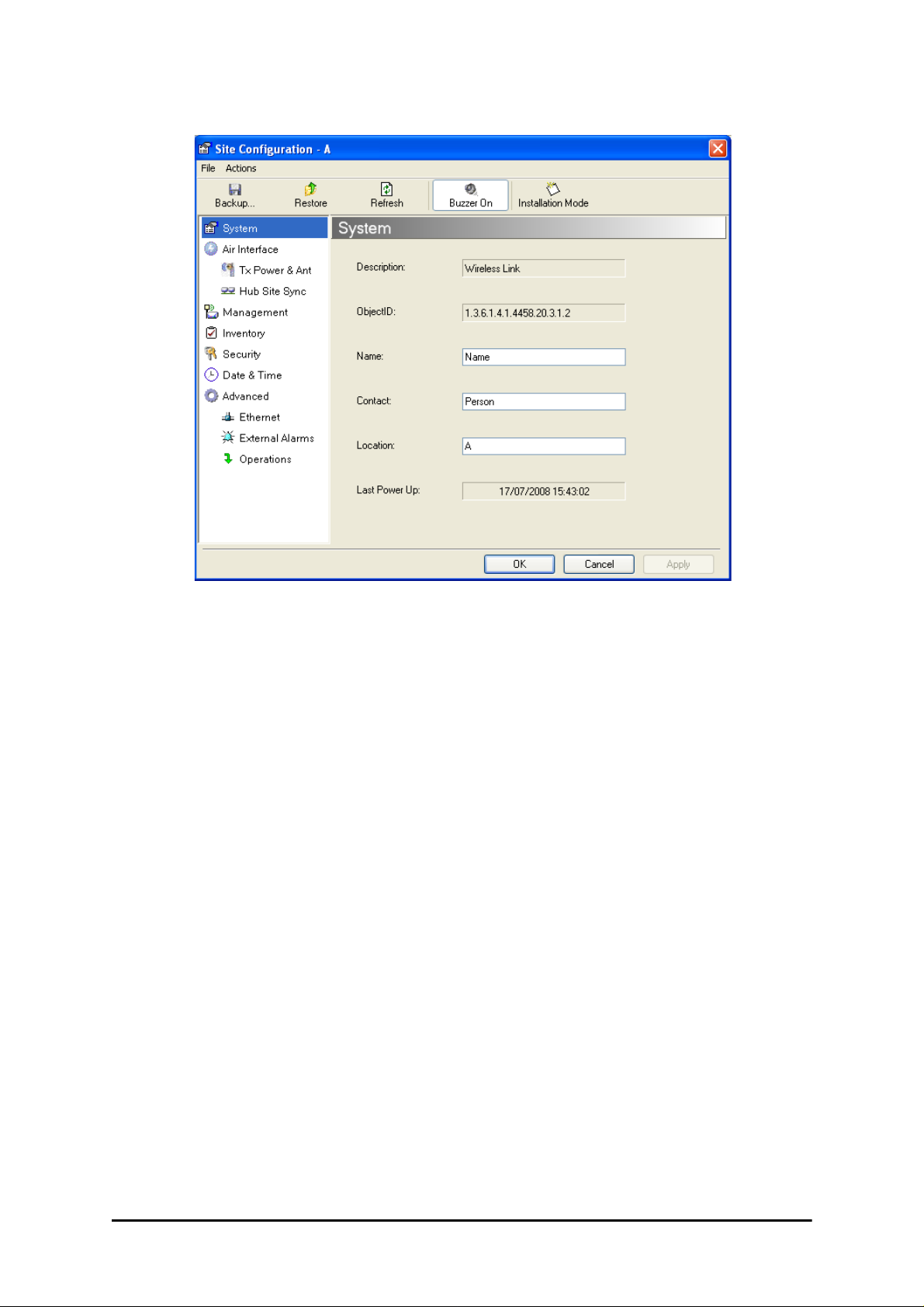
Figure 6-1: Configuration Dialog Box
Functions on the left of the dialog box:
System Edit the contact person and location details.
View the system details
Air Interface Change the transmit power, cable loss, antenna
type and settings
Inventory View the hardware and software inventory
(release numbers, model identification, MAC
address)
Management Configure the IP address, Subnet Mask, Default
Gateway, the Trap Destination and VLAN
Security Change the Community Values and the Link
Password
Date and Time Set the date and time of the link from an NTP
servers otherwise
Advanced Choose Hub or Bridge ODU mode, set the
Ethernet ports configuration, set the external
alarm inputs, restore factory settings
Functions at the top of the dialog box:
Backup Save the current configuration to an .ini file
Restore Restore the link configuration from the .ini file
created by the backup
RADWIN 1000/2000/5000 User ManualVersion 2.6.50p1 6-2
Page 3

Viewing Air Interface Details Chapter 6
Installation
Mode
Mute Mutes the alignment tone in installation mode.
Return to Installation Mode for the entire link.
Selecting the Mute check box before clicking
the Install Mode button mutes the Beeper.
Reactivate the beeper during alignment.
To edit the Configuration Parameters:
1. Click the required site button on the main tool bar of the RADWIN Manager
OR
Click Configuration from the main menu and choose a site to configure.
The Configuration dialog box opens (see figure 6-1 above).
2. Choose the appropriate item in the left hand list to open a dialog box.
3. Click Apply to save changes.
In subsequent instructions, we will simply say “Choose a site to configure”
on the understanding that the foregoing procedure is implied.
Viewing Air Interface Details
Click the Air Interface item in the left hand list. A window similar to the following appears:
Figure 6-2: Air interface details
RADWIN 1000/2000/5000 User ManualVersion 2.6.50p1 6-3
Page 4

Changing the Transmit Power Chapter 6
Changing the Transmit Power
Each site can have a different transmit power level.
To change the Transmit Power:
1. Choose a site to configure.
The Configuration dialog box opens.
2. Choose Air Interface (see figure 6-3).
3. Choose the required Transmit (Tx) Power Level.
4. Click Apply to save the changes.
Figure 6-3: Changing the Transmit Power
The same considerations apply here as were noted in the Installation
procedure on page 4-23.
Note
Site Management: IP Address and VLAN
Configuring the ODU Address
Each site must be configured separately, first site A then site B.
To define the Management Addresses:
1. Choose a site to configure.
RADWIN 1000/2000/5000 User ManualVersion 2.6.50p1 6-4
Page 5
Configuring VLAN Settings Chapter 6
The Configuration dialog box opens:
Note
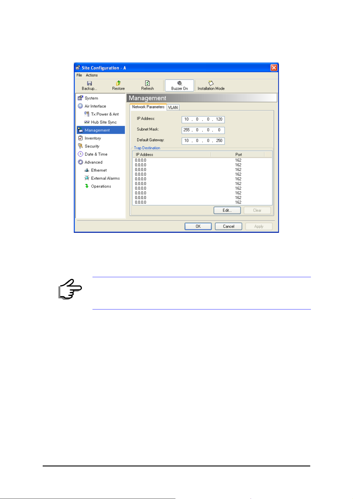
Figure 6-4: Management Addresses - Site Configuration dialog box
5. Choose Management.
6. Enter the IP address of the ODU in the IP Address field.
If performing configuration from the RADWIN Manager, the IP address is
that entered from the login screen.
7. Enter the Subnet Mask.
8. Enter the Default Gateway.
9. Enter the T r ap Destination. This could be the IP address of the managing
computer. The events log will be stored at this address.
10.Click Apply to save the changes.
Configuring VLAN Settings
VLAN Management enables separation of user traffic from management
traffic whenever such separation is required. It is recommended that both
sides of the link be configur ed with dif fer ent VL AN ID s for management tr affic.
To enable VLAN management:
1. Click Configuration from the main menu.
RADWIN 1000/2000/5000 User ManualVersion 2.6.50p1 6-5
Page 6

Configuring VLAN Settings Chapter 6
2. Choose a site to configure. If you are configuring both sites, choose site
B first.
3. Choose Management.
4. Open the VLAN tab.
5. Check the Enabled box.
6. Enter a VLAN ID. Its value should be between 1 and 4094.
After entering the VLAN ID, only packets with the specified VLAN ID are
processed for management purposes by the ODU. This includes all the
protocols supported by the ODU (ICMP, SNMP, TELNET and NTP). The
VLAN priority is used for the traffic sent from the ODU to the managing
computer. Using VLAN for management traffic af fects all types of management connections (local, network and over the air).
7. Enter a Priority number between 0 and 7.
8. Change the VLAN ID and Priority of the managing computer NIC to be
the same as those of steps 6 and 7 respectively.
9. Click Apply or OK.
Figure 6-5: Configuring management traffic VLAN Settings
Changing this parameter causes the RADWIN Manager to immediately
disconnect.To avoid inconvenience, you should verify the change by
setting the VLAN only to one ODU, and only after verifying proper
Caution
RADWIN 1000/2000/5000 User ManualVersion 2.6.50p1 6-6
management operation, change the other ODU VLAN setting.
Page 7

Setting the Date and Time Chapter 6
Lost or forgotten VLAN ID
If the VLAN ID is forgotten or there is no VLAN traffic connected to the
ODU, then reset the relevant ODU.
During the first two minutes of connection to the ODU uses management
packets both with and without VLAN. Y ou may use this period to reconfigure
the VLAN ID and priority.
Setting the Date and Time
The ODU maintains a date and time. The date and time should be synchronized with any Network Time Protocol (NTP) version 3 compatible server.
During power-up the ODU attempts to configure the initial date and time
using an NTP Server. If the server IP address is not configured or is not
reachable, a default time is set.
When configuring the NTP Server IP address, you should also configure the
offset from the Universal Coordinated Time (UTC). If there is no server
available, you can either set the date and time, or you can set it to use the
date and time from the managing computer. Note that manual setting is not
recommended since it will be overridden by a reset, power up, or synchronization with an NTP Server.
The NTP uses UDP port 123. If a firewall is configured between the ODU
and the NTP Server this port must be opened.
Note
It can take up to 8 minutes for the NTP to synchronize the ODU date and
time.
To set the date and time
1. Determine the IP address of the NTP server to be used.
2. Test it for connectivity using the command (Windows XP), for example:
w32tm /stripchart /computer:216.218.192.202
You should get a continuous response of times, each a few seconds
apart.
3. Choose a site to configure.
The Configuration dialog box opens.
4. Choose Date & Time:
RADWIN 1000/2000/5000 User ManualVersion 2.6.50p1 6-7
Page 8

Setting the Date and Time Chapter 6
Figure 6-6: Date and Time Configuration
5. If entering an IP address for the NTP Server, click Clear, and then enter
the new address.
6. Set your site Offset value in minutes ahead or behind GMT
1
.
7 . To manually set the date and time, click Change and edit the new values.
Figure 6-7: Change Date and Time
If you used an NTP Server, you will see a window like this:
1. Greenwich Mean Time
RADWIN 1000/2000/5000 User ManualVersion 2.6.50p1 6-8
Page 9

Ethernet Properties Chapter 6
Figure 6-8: Date and Time configured from an NTP Server
8. Click OK to return to the Configuration dialog.
Ethernet Properties
Configuring the Bridge
Bridge configuration is required in various network topologies, such as protection (1+1) and ring applications. The bridge configuration parameters
are located under the Advanced tab of the Site Configuration dialog box:
RADWIN 1000/2000/5000 User ManualVersion 2.6.50p1 6-9
Page 10
Configuring the Bridge Chapter 6
Note
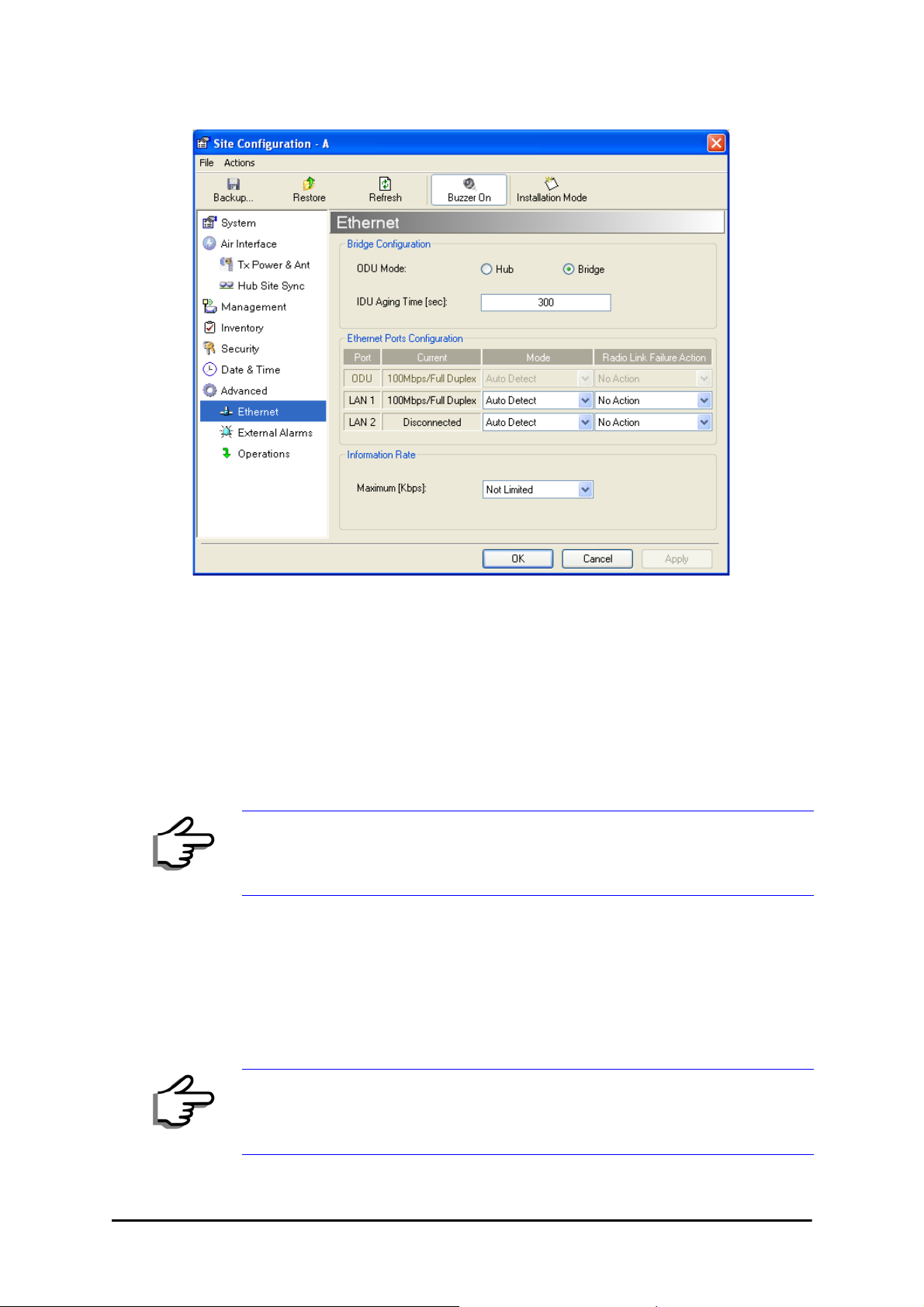
Figure 6-9: Bridge Configuration - Site Configuration dialog box
ODU Mode
This parameter controls the ODU mode with two optional values,
• Hub Mode - in Hub mode the ODU transparently forwards all packets
over the wireless link.
• Bridge Mode - In Bridge mode the ODU performs both learning and
aging, forwarding only relevant packets over the wireless link. The
aging time of the ODU is fixed at 300 seconds.
Changing these modes requires system reset.
IDU Aging time
This parameter controls the IDU aging time.
The aging time parameter controls the time after which each MAC address
is dropped from the MAC address learning table.
The default value is 300 seconds.
• Any change to these parameters is effective immediately.
• Each side of the link can be configured separately.
Note
RADWIN 1000/2000/5000 User ManualVersion 2.6.50p1 6-10
Page 11

Configuring Ethernet Ports Mode Chapter 6
The following table shows the appropriate configuration for several common
scenarios. Both link sites must be configured with the same parameter:
Table 6-1: ODU mode configuration for common
Scenario
Standard (Default) Configuration for
Ethernet Applications
Rapid network topology changes
where fast aging is required
Ethernet Hub Hub N/A
Ethernet Bridge Bridge N/A
ODU
Mode
Bridge 300 sec
Hub 1 sec
IDU Aging
Time
Configuring Ethernet Ports Mode
The ODU Ethernet port is configured to auto-detect by default and may not
be changed.
The ODU Ethernet port mode is configurable for line speed (10/100BaseT)
and duplex mode (half or full duplex).
An Auto Detect feature is provided, whereby the line speed and duplex
mode are detected automatically using auto-negotiation. Use manual configuration when attached external equipment does not support auto-negotiation. The default setting is Auto Detect.
Y ou should not reconfigure the port that is used for the managing computer
connection, since a wrong configuration can cause a management
disconnection or Ethernet services interruption.
Caution
To configure the Ethernet Mode:
1. From the Configuration menu, choose the site to reconfigure.
The Site Configuration dialog box opens.
2. Click Advanced | Ethernet.
3. In the Ethernet Ports Configuration pane, use the drop-down menu to
choose the configuration.
RADWIN 1000/2000/5000 User ManualVersion 2.6.50p1 6-11
Page 12

Setting the Maximum Information Rate Chapter 6
4. Click Apply to save the changes.
It is possible to close the Ethernet service by disconnecting the Ethernet
port.
Note
If you close the port, you may subsequently be unable to access the
device. If this should occur, a workaround is as follows:
• Connect the system from the remote site
• Connect via other Ethernet port (of the IDU)
• Power down the equipment and connect immediately after power
up (the fastest way is to enter install mode)
Setting the Maximum Information Rate
The maximum Ethernet throughput of the link can be limited. The default
setting is Not Limited (see figure 6-9 above), where the highest information rate available for the link conditions and settings is used.
To limit the Ethernet information rate:
1. From the Configuration menu, choose the site to reconfigure.
2. Click Advanced | Ethernet
The Configuration dialog box opens.
3. In the Informat i on Rate pane, use the drop-down menu to choose the
maximum Information Rate.
4. Choose Other to define the throughput with 1 Kbps resolution
5. Choose Not Limited for the highest information rate possible for the
link conditions and settings
6. Click Apply to save the changes.
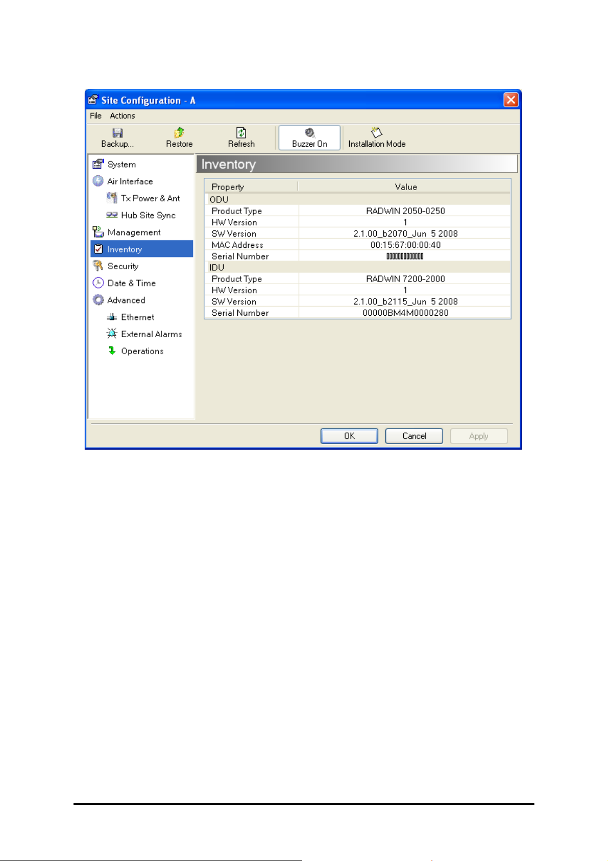
Displaying the Inventory
To view the inventory data
1. Choose a site from the main menu.
The Configuration dialog box opens.
2. Choose Inventory (figure 6-10).
RADWIN 1000/2000/5000 User ManualVersion 2.6.50p1 6-12
Page 13
Security Features Chapter 6
Figure 6-10: Inventory Screen
Security Features
The Security dialog enables you to change the Link Password and the SNMP
Communities details:
RADWIN 1000/2000/5000 User ManualVersion 2.6.50p1 6-13
Page 14

Changing the Link Password Chapter 6
Figure 6-11: Available security features
Changing the Link Password
This item is only available when the link is down. Otherwise, it works the
same way as the corresponding item on page 4-16.
RADWIN Manager Community Strings
The ODU communicates with the application using SNMPv1 protocol. The
protocol defines three types of communities:
• Read-Only for retrieving information from the ODU
• Read-Write to configure and control the ODU
• Trap used by the ODU to issue traps.
The Community string must be entered at login. The user must know the
password and the correct Community string to gain access to the system. A
user may have read-only privileges.
It is not possible to manage the ODU if the read-write or the read Community values are forgotten. A new Community value may be obtained from
RADWIN Customer Support for the purpose of setting new Community; the
serial number or the MAC address of the ODU must be supplied.
The RADWIN Manager uses the Read Community strings public for the site
Al ODU and public-remote for the site B ODU. It uses Write Community
strings netman for the site A ODU and netman-remote for the site B
Note
RADWIN 1000/2000/5000 User ManualVersion 2.6.50p1 6-14
ODU. These are the factory defaults .
Page 15

RADWIN Manager Community Strings Chapter 6
The read-write Community strings and read-only Community strings have a
minimum of five alphanumeric characters. (bru1 and bru4097 are not permitted). Changing the trap Community is optional and is done by clicking
the check box.
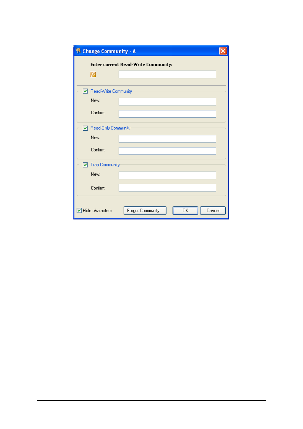
Editing Community Strings
The Community change dialog box is available from the Configuration |
Security tab. Both read-write and read-only communities must be defined.
On logging on for the first time, use the following as the current Community:
• For Read-Write Community, use
• For Read-Only Community, use
• For Trap Community, use
To change a Community string:
1. From the Configuration dialog box, choose the Security tab.
2. Type the current read-write Community (default is
3. Choose the communities to be changed by clicking the check box.
4. Type the new Community string and re-type to confirm.
5. Click OK to save.
public
netman
public
.
.
netman
).
RADWIN 1000/2000/5000 User ManualVersion 2.6.50p1 6-15
Page 16
RADWIN Manager Community Strings Chapter 6
Figure 6-12: Changing the Community String
Forgotten Community string
If the read-write Community string is unknown, an alternative Community
key can be used. The alternative Community key is unique per ODU and can
be used only to change the Community strings. The alternative Community
key is supplied with the product, and should be kept in a safe place.
If both the read-write Community and the alternative Community key are
unavailable, then an alternative Community key can be obtained from RADWIN Customer Support using the ODU serial number or MAC address. The
serial number is located on the product label. The serial number and the
MAC address are displayed in the Site Configuration inventory tab.
When you have the alternative Community key, click the Forgot Commu-
nity button and enter the Alternative Community key (figure 6-13). Then
change the read-write Community string.
RADWIN 1000/2000/5000 User ManualVersion 2.6.50p1 6-16
Page 17

Muting the alignment tone Chapter 6
Figure 6-13: Alternative Community Dialog box
Muting the alignment tone
The ODU alignment tone becomes audible as soon as power is supplied,
and continues until the ODUs are aligned and the link established.
It is possible to mute the tone during regular operation of the link. It must
be enabled when performing the alignment procedure.
To mute the alignment tone:
1. Choose a site.
2. The Configuration dialog box opens.
3. In the Configuration dialog box, click the Buzzer button. The button toggles between on and off .
The tone is disabled.
To restore the alignment tone:
1. Choose a site.
The Configuration dialog box opens.
2. In the Configuration dialog box, click the Buzzer button. The button toggles from on to off. The tone is enabled.
Setting External Alarm Inputs
The IDU-C has two external alarm inputs and two external alarm outputs in
the form of dry-contact relays. The Alarm interface is located on the front
panel of the IDU-C and is a 25-pin D-type female connector. see IDU-C
Alarm Connector on page B-3, for wiring specifications and pinout. The
user enables or disables each of the alarms and can configure the alarm
RADWIN 1000/2000/5000 User ManualVersion 2.6.50p1 6-17
Page 18

Managing Configuration Files Chapter 6
description text that appears in the alarm trap. The ODU sends the alarm
within less than a second from actual alarm trigger.
To set the external alarm inputs:
1. Open the Site Configuration Alarms configuration by clicking Configuration | Advanced.
Figure 6-14: External Alarm Configuration
2. Choose an alarm and set its mode to Enabled or Disabled
3. Enter a description of the alarms in the text field.
4. Click Apply to save.
5. Click OK to exit from the dialog.
Managing Configuration Files
Backup Configuration to a File
RADWIN Manager allows you to backup configuration parameters of the
local and remote units to the managing computer as .ini files. Each site is
backed up in a separate .ini file.
To save the configuration in a file:
1. Choose a site to back up.
The Configuration dialog box opens.
RADWIN 1000/2000/5000 User ManualVersion 2.6.50p1 6-18
Page 19

Restoring a Configuration File Chapter 6
2. Click Backup.
3. In the Save As dialog box, indicate in which folder and under what name
configuration file is to be saved, and click Save.
Restoring a Configuration File
Configuration files (*.ini) can be uploaded from the managing computer.
Such configuration files can be distributed to other units that use the same
configuration.
To restore a configuration file:
1. Choose a site to restore (from a previous backup).
The Configuration dialog box opens.
2. Click Restore.
3. From the Open dialog box choose *.ini file to upload and click OK.
Backup files are specific to a site (IDU / ODU pair and Link ID).
Do not restore a backup configuration file to a site other than that from
Caution
which it was originally taken.
Resetting
Y ou ma y reset the link, preserving the current configuration, or reset to f actory defaults.
Resetting the link causes service disconnection.
To maintain the connection between the managing computer and
Caution
the link, first reset Site B.
To reset the link preserving current configuration:
1. From Maintenance on the main window, reset the remote unit.
2. From Maintenance on the main window, reset the local unit.
To reset to Factory Defaults
1. Choose either of the sites.
The Configuration dialog box opens.
2. Choose Operations in the Configuration dialog box.
3. Click the Restore Defaults button.
A message box asking if you want to restore factory default appears.
4. Click the check box if you want to keep the current IP address settings.
5. Click Yes to continue.
RADWIN 1000/2000/5000 User ManualVersion 2.6.50p1 6-19
Page 20

Configuration with Telnet Chapter 6
Configuration with Telnet
A Telnet terminal can be used to configure and monitor the RADWIN 1000/
2000/5000.
To start a Telnet session, use telnet <manager IP>.
For example, if you run Telnet as follows,
telnet 10.0.0.120
you will be asked for a user name and password.
The login user name/password is identical to the Community strings; Read
allows display only, Read/Write allows display and set commands.
Supported T elnet commands are shown in table 6-2. Note that some of the
commands are model-specific. For example, TDM commands will not apply
to Ethernet only and PoE based links.
Table 6-2: Telnet Commands
Command Explanation
display inventory Displays ODU product name, Name, Location, hardware
and software revisions, uptime, MAC address, IDU product
name, IDU software and hardware revisions
display management Displays IP, Subnet, Gateway, Traps table
display link Displays State, Link ID, Channel BW, RSS, TSL,
Frequency/ACS, DFS, Rate/ARA, Distance
display Ethernet Displays Bridge Mode, Aging time, Port table (State, Status
and action)
display tdm Displays Clock Mode, Master Clock Mode, Current Clock,
Quality[1], TDM table (Line status, Error Blocks)
display ntp D isplays Time, Server and Offset
set ip <ipaddr> <subnetMask>
<gateway>
display PM
<interface:AIR,LAN1,LAN2,TDM1,
TDM2,TDM3,TDM4>
<interval:current,day,month>
Set the ODU IP address, subnet mask and gateway
The user must reset the ODU after the command
completion
Shows the performance monitor tables for each interface
according to user defined monitoring intervals
set trap <index:1-10> <ipaddr>
<port:0-65535>
set readpw <oldpasswd> <passwd> Set the read access password (Read Community)
set writepw <oldpasswd> <passwd> Set the read-write access password (Read-Write
set trappw <oldpasswd> <passwd> Set the trap Community string
set buzzer <mode:0=OFF,1 =ON> Toggle the buzzer mode (0 – off, 1 – on)
Set a specific trap from the traps table (set trap 3
10.0.0.133 162)
Community)
RADWIN 1000/2000/5000 User ManualVersion 2.6.50p1 6-20
Page 21

Configuration with Telnet Chapter 6
Table 6-2: Telnet Commands (Continued)
Command Explanation
set tpc<power:Value between minimal
TX power, and maximal TX power>
set bridge <mode:0=Bridging OFF,1=
Bridging ON >
set name <new name> Set the name of the link
set location <new location> Set the name of the location
Set contact <new contact> Set the name of the site manager
set Ethernet <>port:MNG,LAN1,LAN2>
<mode:AUTO,10H,10F,100H,100F,DIS
ABLE>
Reboot Reset both the IDU and the ODU. The user shall be
Help Displays the available commands
Set the ODU transmit power. If a wrong value is entered,
both min and max values shall be displayed in the error
reply
Set the ODU bridge mode (0 – off, 1 – on)
Set the mode and speed of each ethernet port
prompt that the command will reset the card and that he
has to reconnect the telnet session after TBD seconds.
RADWIN 1000/2000/5000 User ManualVersion 2.6.50p1 6-21
Page 22

Configuration with Telnet Chapter 6
figure 6-15, below, shows the available Telnet commands via the Help
command.
Hello admin, welcome to ODU Management CLI!
+-----------------------------------------------------------+
Software Revision 2.1.00_b2070_Jun 5 2008
+-----------------------------------------------------------+
admin@10.0.0.120-> Type "help" for help.
admin@10.0.0.120-> help
display inventory
display management
display link
display ethernet
display tdm
display ntp
display PM <interface:AIR,LAN1,LAN2,TDM1,TDM2,TDM3,TDM4>
<interval:current,day,month>
set ip <ipaddr> <subnetMask> <gateway>
set trap <index:1-10> <ipaddr> <port:1-65535>
set readpw <writePasswd> <newPasswd>
set writepw <writePasswd> <newPasswd>
set trappw <writePasswd> <newPasswd>
set buzzer <mode:0=OFF,1=ON>
set tpc <power:Value between minimal TX power, and maximal TX power>
set bridge <mode:0=Bridging OFF,1=Bridging ON>
set name <new name>
set location <new location>
set contact <new contact>
set ethernet <port:MNG,LAN1,LAN2> <mode:AUTO,10H,10F,1 00H ,100F,DISABLE>
reboot
help
Command "help" finished OK.
Figure 6-15: Telnet Management Screen
RADWIN 1000/2000/5000 User ManualVersion 2.6.50p1 6-22
Page 23

Chapter 7
Monitoring and
Diagnostics
The RADWIN Manager application enables you to monitor the link, as well
as perform diagnostic operations such as loopback tests.
This chapter covers:
• Retrieving link information
• Link compatibility issues
• Reinstalling and realigning a link
• Performance monitoring
• Troubleshooting
•Replacing an ODU
• Restoring to factory setup
Retrieving Link Information (Get Diagnostics)
The Get Diagnostics feature collects and writes all link and Manager information (from both sites) into a text file. The file information can be used for
diagnostics and should be sent to RADWIN Customer Support to speed up
assistance.
RADWIN 1000/2000/5000 User ManualVersion 2.6.50p1 7-1
Page 24

Retrieving Link Information (Get Diagnostics) Chapter 7
The following table lists link and system information that can be monitored.
Table 7-1: Get Diagnostics Data and Description
Data Description
System Data General information about the system
Link Information Information about the link properties
Events Log List of recent system events
Site Configuration Data about the site parameters
Active Alarms List of active alarms
Performance Monitor Network performance data over defined time periods
Monitor Detailed event data record
To get diagnostics
1. On the Help menu, choose Get Diagnostic Information.
Figure 7-1: Get Diagnostics Dialog Box
2. Select or deselect the data options. If the file is to be sent to RADWIN
Customer Support leave all options checked.
3. Click File Path to specify the folder in which you want to save the file
and then click Start to save the information.
The file is saved in the specified folder as Diagnostics Informa-
tion.txt
RADWIN 1000/2000/5000 User ManualVersion 2.6.50p1 7-2
Page 25

Link Compatibility Chapter 7
Link Compatibility
Link Compatibility indicates the version compatibility using software traps.
As new hardware or software is added to existing networks compatibility
issues may arise. An incompatibility issue is indicated to the user by a
change of color of the Link Status box on the Main Menu screen. Trap messages in the events Log indicate the problems or limitations and suggest
upgrades when appropriate.
The following Link Status messages are given:
fullCompatibility - different software versions were detected that are fully
compatible. The message indicates that an upgrade is available.
restrictedCompatibility - different software versions were detected that
operate correctly. However, new features are not supported
softwareUpgradeRequired - different software versions were detected allow-
ing limited operation. The message is, that a software upgrade required.
versionsIncompatibility - different software versions were detected that are
incompatible. You need to perf orm local upgrades.
Table 7-2: Link Compatibility Trap Messages
Link State
fullCompatibility Active
restrictedCompatibility Active - SW
softwareUpgradeRequired Active – SW
versionsIncompatibility Not Active -
Link State
text
Version mismatch
Upgrade
Required
SW
Upgrade
Required
Link
Status
Color
Green SW Upgrade
Magenta
(Same as
authentication
error)
Brown
(Major)
Red Local SW
Site
Description
Available
SW Upgrade
Recommended
SW Upgrade
Required
Upgrade
Required
Site
Desc.
Color
Yellow Green
Yellow Magenta
Yellow Brown (Major)
Yellow Red
Link Status
Color
(Same as
authentication
error)
Reinstalling and Realigning a Link
It may be necessary to reinstall the link if the ODUs need to be realigned.
Activating Install Mode causes both sites to go into install mode, causing
disruption in service for approximately fifteen seconds.
Note
RADWIN 1000/2000/5000 User ManualVersion 2.6.50p1 7-3
Page 26

The Link Budget Calculator Chapter 7
To reinstall the link:
1. Choose a site.
The Configuration dialog box opens.
2. In the Configuration dialog box, click the Install Mode button.
A message box asking if you want to enter install mode appears.
3. Click Yes to continue.
The system enters Install mode and the alignment tone becomes audi-
ble.
4. Realign the ODUs and start the Installation wizard (see chapter 4).
The Link Budget Calculator
The Link Budget Calculator is part of the RADWIN Manager software and is
found in the Help menu. This useful utility enables you to calculate the
expected performance of the wireless link and the possible configurations
for a specific link range including antenna size, cable loss and climate conditions. For full details, see appendix D.
Performance Monitoring
RADWIN 1000/2000/5000 Performance Monitoring constantly monitor s traffic over the radio link and collects statistics data for the air interface and
Ethernet ports. It does so continuously, even when the RADWIN Manager is
not connected.
Two types of logs are recorded:
• Monitor Log that records statistics on traffic rate and radio signal
strength.
• Events Log that records when the rates fall above or below a predefined threshold.
Both the statistics Monitor log and events log can be saved as TXT files.
The Monitor Log
The Monitor Log records performance statistics for predefined intervals. You
can save the monitor log to a text file, as well as display the information in
an on-screen report.
Saving the Monitor Log
You can save the recorded Monitor Log statistics to a text file.
To save the monitor log:
1. From the Tools menu, choose Preferences.
The Preferences dialog box appears:
RADWIN 1000/2000/5000 User ManualVersion 2.6.50p1 7-4
Page 27

The Monitor Log Chapter 7
Figure 7-2: Preferences dialog box
2. Click the Monitor Tab.
3. Select the file to save.
4. Click the check box to open the file for saving.
5. Click the button and in the Select File dialog box indicate in which
folder and under what name the monitor log file is to be saved.
6. Set the time interval for adding data to the file.
7. Click OK to save the file.
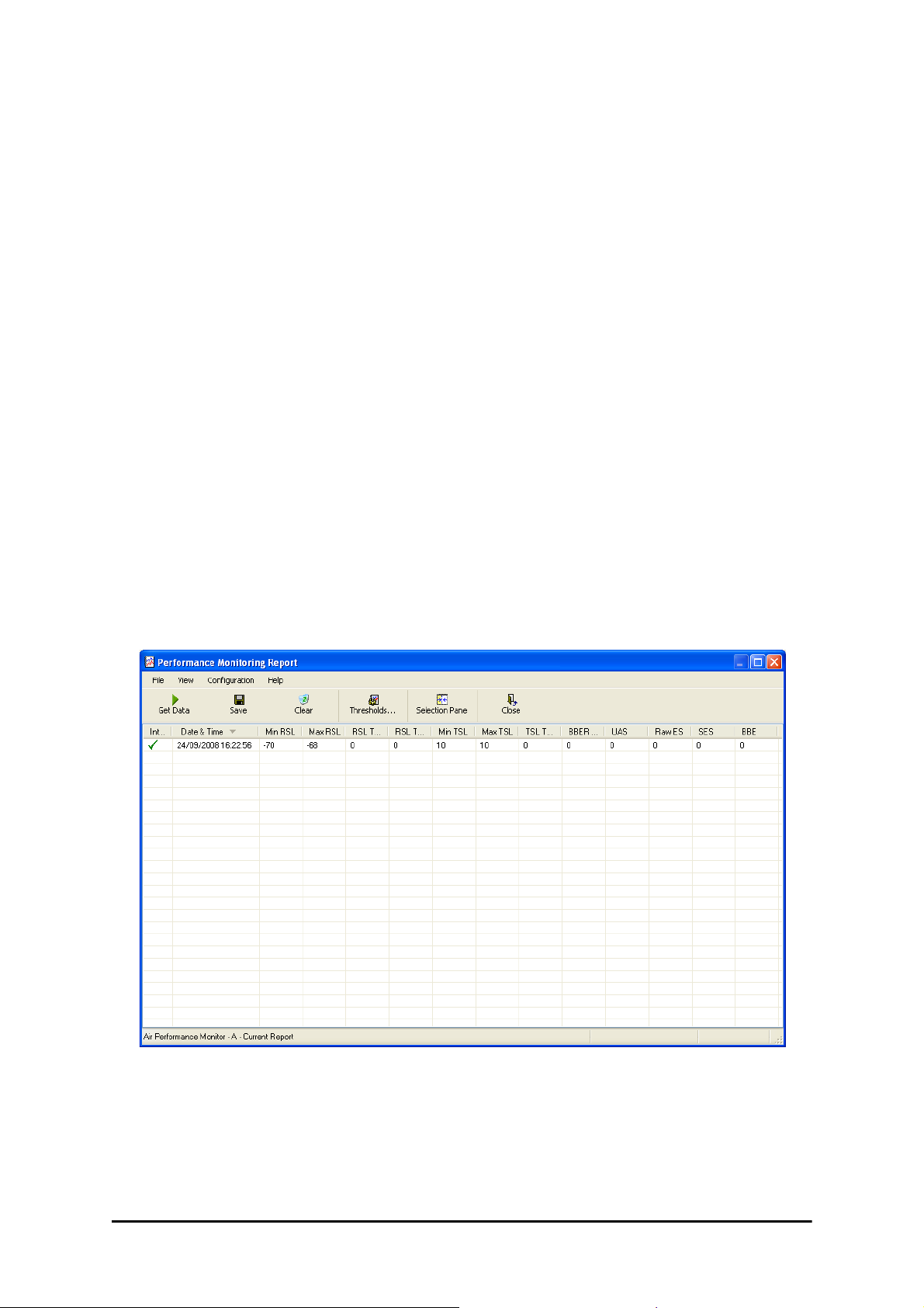
Viewing Performance Reports
The Performance Monitor Report displays performance views of each of the
1
interfaces
.
To obtain performance monitoring reports:
1. From the main menu, choose Tools | Performance Monitoring
Report ...
You are presented with the following window:
1. Ethernet performance is not collected from PoE devices.
RADWIN 1000/2000/5000 User ManualVersion 2.6.50p1 7-5
Page 28
The Monitor Log Chapter 7
Figure 7-3: Basic Performance Monitoring Report
2. Choose a report type from the left panel and click the Get Data toolbar
button. For example, if you choose Site A, Air and Current, you will be
offered a report looking like this:
Figure 7-4: A typical Performance Monitoring Report
Y ou can click the Selection Pane icon to toggle the side panel on or off.
The other reports look similar. Here is a detailed description of the reports
and their fields:
RADWIN 1000/2000/5000 User ManualVersion 2.6.50p1 7-6
Page 29

The Monitor Log Chapter 7
Several performance data occurrences are collected for each of the interfaces (ES, SES, and UAS), as well as Specific data per Interface type (e.g.,
TX and RX bytes for Ethernet). For the Air Interface, user defined thresholds
data are collected. Refer to table 7-3 and table 7-4, in Performance
Monitoring Report Toolbar below.
Data is collected and selectively displayed based on three time intervals as
selected by the Interval radio buttons:
• Current (t=0)
• 15 minutes Intervals
• Daily
RADWIN 1000/2000/5000 User ManualVersion 2.6.50p1 7-7
Page 30

The Monitor Log Chapter 7
Table 7-3: Explanation of performance data
Data type Reported Value Explanation
Generic PM Data
UAS – Unavailable
Seconds
ES – Errored Seconds
SES – Severe Errored
Seconds
BBE – Background
Block Error
Integrity A flag indicating that the data was valid. Note that
Max RSL The maximum of the receive signal level (mea-
Min RSL The minimum of the receive signal level (measured
Seconds in which the interface was out of service.
The number of seconds in which there was at least
one error block. Note that the notation of an error
block is different per interface.
The number of seconds in which the service quality
was low (the quality is different per type of interface and determined by the BBER threshold per
interface).
The number of errored blocks in an interval.
the Performance Monitoring data is not valid if not
all the values were stored (e.g., due to clock
changes within the interval or power up reset).
sured in dBm).
in dBm).
Air Interface PM
Data
Ethernet Interface
PM Data
Max TSL The maximum of the transmit signal level (mea-
sured in dBm).
Min TSL The minimum of the transmit signal level (mea-
sured in dBm).
RSL Threshold 1 The number of seconds in which the RSL was
below the specified threshold.
RSL Threshold 2 The number of seconds in which the RSL was
below the specified threshold.
TSL Threshold The number of seconds in which the RSL was
above the specified threshold.
BBER Threshold The BBER Threshold value counts the number of
seconds in which the Background Block Error Ratio
(BBER) exceeded the specified threshold.
Received Bytes The number of Megabytes received at the specified
port within the interval
Tr ansmitted Bytes The number of Megabytes transmitted at the spec-
ified port within the interval.
RADWIN 1000/2000/5000 User ManualVersion 2.6.50p1 7-8
Page 31

The Monitor Log Chapter 7
Performance Monitoring Report Toolbar
You can use the toolbar to perform the actions described in the following
table:
Table 7-4: Action of the toolbar buttons
Command Button Action
Get Data Gathers current performance monitoring data.
Save Save current performance monitoring data to a file
Clear Clear current performance monitoring data.
Thresholds Set Air Interface Thresholds
Close Closes the active alarm window.
Setting Air Interface Thresholds
Use the Thresholds button on the Monitoring Performance Report toolbar to
set the Air Interface Thresholds:
Figure 7-5: Threshold configuration dialog box
BBER Threshold
This parameter counts the seconds during which the radio performance is
below a user specified threshold. The threshold is measured as a percentage. The threshold can be set from 0.1% up to 50%.
For links with Ethernet only service, 8% threshold is recommended. If there
are no problems during the interval, then for that threshold, the recommended BBER value should be 0. Since the system provides a lossless
Ethernet service, there is throughput degradation in case of interference.
The degradation is proportional to the BBER.
RSL Threshold
RSL Threshold can also be used as an indicator of problems in the radio
channel. You can check the RSS by from the Link Budget Calculator results
RADWIN 1000/2000/5000 User ManualVersion 2.6.50p1 7-9
Page 32

The Events Log Chapter 7
during installation. A value of -5dB from the current RSS is recommended as
a threshold.
The Events Log
The Events Log records system failures, loss of synchronization, loss of signal, compatibility problems and other fault conditions and events.
Alarms (traps) are displayed in the Events Log in the lower panel of the
main window. The Events Log may be saved as a text file.
The Events Log includes the following fields:
Sequential number (ID)
Date and time stamp
Message
Trap source
IP address of the ODU that initiated alarm.
For complete information about traps and alarms see appendix G, MIB
Reference, table G-3.
The events are displayed in the Events Log in the lower part of the RADWIN
Manager main window:
Figure 7-6: Events Log Display
RADWIN 1000/2000/5000 User ManualVersion 2.6.50p1 7-10
Page 33

RADWIN Manager Traps Chapter 7
RADWIN Manager Traps
The RADWIN Manager application issues traps to indicate various events,
displayed in the Wvents Log.
Table 7-5: RADWIN Manager Trap Messages
Trap Message Severity Remarks
Error loading trap catcher. Port 162 is already in use. Warning NMS will not catch any
traps from target, some
other application has
grabbed this port
Device unreachable! Error Check connectivity to target
Connected to <site_name> Information
<site_name> Site will be reset. Information
Restore Factory Default Settings in process on Site
<site_name>
Factory Settings: The pr ocess was not finished due to
connection issues.
Reset: The process was not finished due to connection issues.
Cannot Write to Monitor file. There is not enough
space on the disk.
Windows Error: <error_ID>. Cannot Write to Monitor
file.
TDM Counters were cleared for both sides Information
Identical IP addresses at <local_site_name> and
<remote_site_name>
The Product is not identified at the
<local_site_name> site.
The Product is not identified at the
<remote_site_name> site.
Information
Warning Factory setting f ailed due to
Warning Factory setting f ailed due to
Warning Free some space on disk
Warning Operating System error
Warning Set up a different IP to each
Warning NMS is incompatible with
Warning
connectivity problem to tar-
get
connectivity problem to tar-
get - Target will not be reset
and retry
site
the target release
The Product is not identified at both sites. Warning
Product Not Identified! Warning
The Manager identified a newer ODU release at the
<remote_site_name> site.
The Manager identified a newer ODU release at both
sites.
Warning ODU release is newer than
NMS release. Wizards are
not available. NMS will be
used just for monitoring.
Upgrade the NMS. (Y ou will
get this message as a pop
up)
Warning
RADWIN 1000/2000/5000 User ManualVersion 2.6.50p1 7-11
Page 34

RADWIN Manager Traps Chapter 7
Table 7-5: RADWIN Manager Trap Messages
Trap Message Severity Remarks
The Manager identified a newer ODU release at the
<local_site_name> site.
Newer Version identified at the <local_site_name>
site.
Newer Version identified at the <r emote_ site_ name >
site.
Newer Version Identified! Warning
Warning
Warning ODU release is newer than
Warning
Setting the Events Preferences
You can define a color for the traps to be displayed in the Event Log window, according to the severity of the event. The severity is predefined.
To set the trap color:
1. From the Tools menu, choose Preferences.
The Preferences dialog box appears.
2. Click the Events Tab:
NMS release. Wizards are
not available. NMS will be
used just for monitoring.
Upgrade the NMS
Figure 7-7: Preferences dialog box
RADWIN 1000/2000/5000 User ManualVersion 2.6.50p1 7-12
Page 35

RADWIN Manager Traps Chapter 7
3. Select the event type and click on the button.
A color chart opens.
4. Select the desired color.
5. Repeat for all of the event types.
To set the trap background color:
• Click Background Color to change the text background.
To reset the event colors:
• Click Reset Settings to return to the default color settings.
Saving the Events Log
You can save recorded events in an Events Log text file. New alarms are
automatically added to the text file, as they enter the Events Log.
To save the Events Log:
Note
1. From the Tools menu, choose Preferences.
The Preferences dialog box appears
2. Click the Events Tab.
3. Select the file to save.
4. Click the check box to open the file for saving.
Click the button and in the Select File dialog box indicate in which f older
and under what name the Events Log file is to be saved, and click OK.
To store the Events Log, first define the IP address, subnet mask, default
gateway and trap address of the managing computer (see Configuring
the ODU Address on page 6-4 for details).
Reverting Alarm Messages
Alarm messages can be reverted to their default values by choosing the
Advanced tab from the Preferences dialog:
RADWIN 1000/2000/5000 User ManualVersion 2.6.50p1 7-13
Page 36

RADWIN Manager Traps Chapter 7
Just click the Restore Defaults button, followed by OK.
Active Alarms
Upon setting a trap destination, applicable events are reported as active
alarms to the user. The active alarms are saved and can be viewed in the
Active Alarms window.
To view summary of saved alarms:
• From the Tools menu, choose Active Alarm Summary.
The Active Alarms Summary window opens:
RADWIN 1000/2000/5000 User ManualVersion 2.6.50p1 7-14
Page 37

RADWIN Manager Traps Chapter 7
Figure 7-8: Active Alarms Summary
The following table provides an explanation of the command buttons
Table 7-6: Active Alarms command buttons
Command Action
Save Saves the alarms in CSV or text format for further analysis.
Refresh Reads the alarms from the ODU.
Site Selects site for the active alarms.
Close Closes the active alarm window.
Remote Power Fail Indication
Remote power fail indication indicates to one side that the other side has
had a power failure. The failed site sends a final trap indication about the
power loss just before powering off.
A “Dying-Gasp” circuit identifies the power failure at a minimum interval of
20 milliseconds before the ODU or IDU powers off. During that interval a
message notifying the power failure is sent to Site B. Alarm output number
4 indicates power failure at Site B.
RADWIN 1000/2000/5000 User ManualVersion 2.6.50p1 7-15
Page 38

Troubleshooting Chapter 7
Troubleshooting
Use the following table to troubleshoot LED fault indications:
Table 7-7: LED fault indicators
LED Status Remedy
PWR Off Check that AC adapter is connected to the IDU-E and the AC
power outlet.
IDU Orange Check that the IDU/ODU cable is properly wired and connected.
ODU Red Check that the IDU/ODU cable is properly wired and connected.
AIR I/F Orange Complete the installation procedure from the management soft-
ware.
Red Check the ODU Antenna alignment. Check that the radio configu-
ration of both site A and site B units are the same (channel and
Link ID).
SVC Off
Use the following table to troubleshoot faults in the system:.
Table 7-8: Troubleshooting
Symptom Remedy
No power Ensure that power is connected to the IDU.
Ensure that the ODU cable is properly wired and connected.
No signal Complete the installation procedure from the RADWIN Manager
Check the ODU alignment. Check that the ra dio configuration of both site A
and site B units are the same (channel and Link ID.
Weak signal
received
Check the ODU alignment, reconfigure the link.
Check the alignment tone sounds the Best Signal sequence.
Replacing an ODU
Prior to any action ensure that both ODUs have the same software version.
You can see this on the inventory panels for each site.
For Site A, click Site A | Inventory and note the ODU software version.
Repeat this for Site B using Site B | Inventory.
If either ODU has an old software version, perform a software upgrade. It is
important to configure the new ODU exactly the same as the old ODU to
avoid configuration mismatches, which will disrupt the link.
An ODU may be reconfigured in several ways.
• Use the backup Configuration
If a backup of the configuration is available, re store that configuration using Site A| Restore.
RADWIN 1000/2000/5000 User ManualVersion 2.6.50p1 7-16
Page 39

Restoring Factory Setup Chapter 7
• Manual Configuration
The new ODU can be configured manually according to the link configuration. Remember to use the same settings for Link ID, channels, link password, IP addresses, and names.
Restoring Factory Setup
To restore factory setup:
1. Set the remaining ODUs back to the factory setup by using the Site A
|Advanced option.
2. Activate the second ODU and carry out a new Installation.
Online Help
Online help can be accessed from the Help menu on the main screen of the
RADWIN 1000/2000/5000 Manager.
Figure 7-9: Online Help for RADWIN 1000/2000/5000
Customer Support
Customer support for this product can be obtained from the local VAR, Integrator or distributor from whom it was purchased.
For further information, please contact the RADWIN 1000/2000/5000 distributor nearest to you or one of RADWIN's offices worldwide (see RAD-
WIN Worldwide Offices at the beginning of this manual).
RADWIN 1000/2000/5000 User ManualVersion 2.6.50p1 7-17
Page 40

Appendix A
Technical Specifications
Configuration
ODU: Outdoor Unit with Integrated Antenna or Connector-
Architecture
IDU to ODU Interface Outdoor CAT-5e cable; Maximum cable length: 100 m
Radio
Capacity
ized for External Antenna
IDU: Indoor Unit for service interfaces or PoE device for
Ethernet only
Up to 270Mbps at 40MHz channel bandwidth in the 5.3/5.4
IC and 5.8 GHz spectrum bands
Up to 130Mbps at 20MHz channel bandwidth in the 3.5/3.6
GHz spectrum bands
Range Up to 120 km / 75 miles
5, 10, and 20 MHz
Channel Bandwidth
40 MHz in the 5.3/5.4 IC and 5.8 GHz spectrum bands
RADWIN 1000/2000/5000 User ManualVersion 2.6.50p1 A-1
Page 41

Radio Appendix A
Band Regulations
5.725 – 5.850 GHz FCC / IC
5.725 – 5.825 GHz FCC(UNII)/IC
5.250 – 5.350 GHz (excluding 40 MHz channel bandwidth and 6dBi antenna
assembly gain)
5.250 – 5.350 GHz (including
40 MHz channel bandwidth
and 6dBi antenna assembly
gain)
FCC
IC
Frequency Bands
Band Max Tx Power Antenna
5.470 – 5.725 GHz (excluding 40 MHz channel bandwidth and 6dBi antenna
assembly gain)
5.470 – 5.725 GHz (including
40 MHz channel bandwidth
and 6dBi antenna assembly
gain)
4.940 – 4.990 GHz
3.650 – 3.700 GHz
3.475 – 3.650 GHz IC
29.95 dBm 28 dBi Dish
29.95 dBm 24 dBi Integral Flat
FCC
IC
FCC2.400 – 2.4835 GHz
5.725 – 5.850 GHz
29.95 dBm 23 dBi External Flat
23 dBm 14 dBi External Flat
20 dBm 16.5 dBi External Flat
28 dBm 8 dBi assembly
RADWIN 1000/2000/5000 User ManualVersion 2.6.50p1 A-2
Page 42

Radio Appendix A
Band Max Tx Power Antenna
1.9 dBm 28 dBi Dish
6.5 dBm 23.5 dBi Integral Flat
7.5 dBm 22.5 dBi External Flat
5.250 – 5.350 GHz
5.470 – 5.725 GHz
5.725 – 5.825 GHz
23.5dBm 6 dBi assembly
7.4 dBm 14 dBi External Flat
7.4 dBm 15.5 dBi External Flat
23.5 dBm 6 dBi assembly
1.6 dBm 28 dBi Dish
6.3 dBm 23.5 dBi Integral Flat
7.3 dBm 22.5 dBi External Flat
23.7 dBm 6 dBi assembly
7.2 dBm 14 dBi External Flat
7.2 dBm 16.5 dBi External Flat
23.7 dBm 6 dBi assembly
23.8 dBm 28 dBi Dish
26.4 dBm 22.5 dBi Integral Flat
26.4 dBm 23.5 dBi External Flat
29.4 dBm 6 dBi assembly
24.4 dBm 14 dBi External Flat
24 dBm 16.5 dBi External Flat
29.3 dBm 6 dBi assembly
4.940 – 4.990 GHz 31 dBm
25.5 dBm(*) 20 dBi External Flat
25.5 dBm(*) 17.5 dBi Integral Flat
2.400 – 2.4835 GHz
23.7 dBm 20 dBi External Flat
23.7 dBm 17.5 dBi Integral Flat
3.475 – 3.650 GHz 26 dBm
21 dBi Integral Flat
21 dBi External Flat
28 dBi Dish
14 dBi External Flat
15 dBi External Flat
21 dBi Integral Flat
22 dBi External Flat
24 dBi Dish
13 dBi External Flat
RADWIN 1000/2000/5000 User ManualVersion 2.6.50p1 A-3
Page 43

Radio Appendix A
Band Max Tx Power Antenna
13.5 dBi assembly
13 dBi External Flat
21 dBi Integral Flat
22 dBi External Flat
3.650 – 3.700 GHz
26 dBm
20 dBm
17 dBm 24 dBi Dish
24 dBm 17 dBi assembly
(*) Relevant for RADWIN 1000 RW-1020-0150 / RADWIN 2000 RW-20200150 models only
Channel Bandwidth
Radio Modulation 2x2 MIMO-OFDM (BPSK/QPSK/16QAM/64QAM)
Adaptive Modulation &
Coding
Automatic Channel Selection Supported
Radio Regulation
5, 10, and 20 MHz, (10MHz not supported in the 5.8 GHz
band)
Supported
FCC 47 CFR Part 15 Subpart C, E, Part 90 Subpart Y, Z
IC (Canada) RSS-210, RSS-111, RSS-192, RSS-197
Duplex Technology TDD
Error Correction FEC k = 1/2, 2/3, 3/4, 5/6
Encryption AES 128
Rate – Single Antenna
[Mbps]
Rate – Single Antenna in the
5.8 GHz spectrum band
[Mbps]
Rate – Dual Antenna [Mbps] 13 26 39 52 78 104 117 130
Rate –Dual Antenna in the
5.8 GHz spectrum band
[Mbps]
Modulation BPSK QPSK 16QAM 64QAM
FEC [k=] 1/2 1/2 3/4 1/2 3/4 2/3 3/4 5/6
Max Tx Power [dBm] 25 24 21 19 18
6.5 13 19.5 26 39 52 58.5 65
13.5 27 40.5 54 81 108 121.5 135
27 54 81 108 162 216 243 270
Sensitivity (dBm) @BER
<10e-11 (20MHz)
-88 -86 -83 -81 -80 -72 -70 -67
RADWIN 1000/2000/5000 User ManualVersion 2.6.50p1 A-4
Page 44

Ethernet Interface Appendix A
Ethernet Interface
Throughput
Number of Ethernet ports IDU-C and E: 2; PoE Device: 1
Type 10/100BaseT with Auto-Negotiation (IEEE 802.3u)
Framing/Coding IEEE 802.3
Line Impedance 100 Ω
VLAN Support Transparent
Connector RJ-45
Maximum Frame Size 2048 Bytes
Bridge
Latency 3 msec (typical)
Up to 270Mbps in the 5.3/5.4 IC and 5.8 GHz spectrum
bands
Layer 2, self-learning of up to 2047 MAC addresses (IEEE
802.1Q), hub/Bridge selectable mode
Management
Management Application RADWIN Manager
Protocol SNMP and Telnet
Mechanical
ODU with Integrated Antenna: 37.1/14.84(W) x 37.1/
14.84(H) x 9.00/3.6(D) cm/in; 3.5 kg / 7 lbs
ODU Connectorized: 18.0/7.2(W) x 27.0/10.8(H) x 5.5/
Dimensions
2.2(D) cm/in; 1.5 kg / 3.0 lbs
IDU-C: 43.6/17.2(W) x 4.5/1.7(H) x 21/8.3(D) cm; 1.5 kg /
3.3 lbs
IDU-E: 22/8.7(W) x 4.4/1.7(H) x 17/6.7(D) cm/in; 0.5 Kg /
1.1 lbs
Power
Power Feeding Dual feeding, -20 to -60 VDC (AC/DC converter is available)
Power Consumption < 35 W (IDU+ODU)
Environmental
ODU: -35°C to +60°C / -31°F to +140°F
Operating Temperatures
Humidity
IDU-C: 0°C to +50°C / 32°F to +122°F
IDU-E: -5°C to 45°C / 32°F to 122°F
ODU: Up to 100% non-condensing, IP67
IDU: 90% non-condensing
RADWIN 1000/2000/5000 User ManualVersion 2.6.50p1 A-5
Page 45

Safety Appendix A
Safety
FCC/IC (cTUVus) UL 60950-1, CAN/CSA 60950-1 C22.2
ETSI EN/IEC 60950-1
EMC
FCC CFR47 Class B, Part15, Subpart B
ETSI
CAN/CSA-CEI/IEC CISPR 22-02
AS/NZS CISPR 22:2002
EN 300 386 (2005), EN 301 489-1 (2001), EN 301 489-4
(2002)
Air Interface
RADWIN 1000/2000/5000 is available in several different frequency band
ranges that comply with ETSI, FCC and IC regulations.
The RADWIN 1000 RW-1020-0150 / RADWIN 2000 RW-2020-0150 is available only in the 2.4GHz frequency band range that complies with FCC and
IC regulations.
The RADWIN 1000 3GHz Band / RADWIN 2000 3GHz Band / RADWIN 5000
3GHz Band support the 3.5 / 3.6 GHz frequency bands and comply with FCC
and IC regulations.
RADWIN 1000/2000/5000 User ManualVersion 2.6.50p1 A-6
Page 46

Wiring Specifications
ODU-IDU Cable
The ODU-IDU cable is shielded/outdoor class CAT-5e, 4 twisted-pair 24
AWG terminated with RJ-45 connectors on both ends. A cable gland on the
ODU side provides hermetic sealing.
The following table shows the connector pinout:
Table B-1: ODU-IDU Connector Pinout
Appendix B
Function Color IDU RJ-45
Ethernet (RxN) White/Green 1 twisted
Ethernet (RxT) Green 2
Ethernet (TxT) White/Orange 3 twisted
Ethernet (TxN) Orange 6
Power (+) Blue 4 twisted
Power (+) White/Blue 5
Power () White/Brown 7 twisted
Power ()Brown 8
User Port Connectors
LAN Port
The LAN 10/100BaseT interface terminates in an 8-pin RJ-45 connector,
wired in accordance to table B-2.
ODU
RJ-45
1
2 pair
3
6 pair
4
5 pair
7
8 pair
RADWIN 1000/2000/5000 User ManualVersion 2.6.50p1 B-1
Page 47

LAN Port Appendix B
Table B-2: Fast Ethernet Connector Pinout
Pin Signal Function
1 TD (+) Transmit Data
(positive)
2 TD (–) Transmit Data
(negative)
3 RD (+) Receive Data
(positive)
6 RD (–) Receive Data
(negative)
RADWIN 1000/2000/5000 User ManualVersion 2.6.50p1 B-2
Page 48

IDU-C Alarm Connector Appendix B
IDU-C Alarm Connector
The IDU-C Alarm interface is a 25 pin D type female connector. Its pinout is
listed in table B-3.
Table B-3: IDU-C Alarm Connector (Dry-Contact)
I/O Description Pin
Input 1 Positive 14
Input 1 Negative 15
Input 2 Positive 16
Input 2 Negative 17
Input 3 Positive 18
Input 3 Negative 19
Input 4 Positive 20
Input 4 Negative 21
Output 1 Normally Open 1
Output 1 Common 2
Output 1 Normally
Closed
Output 2 Normally Open 4
Output 2 Common 5
Output 2 Normally
Closed
Output 3 Normally Open 7
Output 3 Common 8
Output 3 Normally
Closed
Output 4 Normally Open 10
3
6
9
Output 4 Common 11
Output 4 Normally
Closed
12
The following diagram describes how to connect external input and output
alarms.
RADWIN 1000/2000/5000 User ManualVersion 2.6.50p1 B-3
Page 49

IDU-C Alarm Connector Appendix B
• Use an external current limit resistor to limit the current at the output
relays to 1 Ampere. Such resistor is not required if the equipment
Note
connected to the IDU supports current limiting to 1 Amp.
• The voltage of the input alarm must be within the range of -10 to -50
VDC.
Figure B-1: Example for connecting the alarm connector
DC Power Terminal
Table B-4: Terminal Block 3-pin -48VDC
Function Pin
+Right
Chassis Center
–Left
RADWIN 1000/2000/5000 User ManualVersion 2.6.50p1 B-4
Page 50

Appendix C
Pole and Wall Installation
ODU Mounting Kit Contents
Table C-1: Bill of Materials: ODU mounting kit
Item Qty
Large Clamp (see figure C-1)
Small Clamp (see figure C-2)
Arm (see figure C-3)
Screw hex head M8x40
Screw hex head M8x70
Washer fla t M8
Washer spring M8
M8 Nuts
1
1
1
4
2
4
3
2
Figure C-1: Large Clamp Figure C-2: Small Clamp Figure C-3: Arm
RADWIN 1000/2000/5000 User ManualVersion 2.6.50p1 C-1
Page 51

Mounting RADWIN 1000/2000/5000 on a pole Appendix C
Mounting RADWIN 1000/2000/5000 on a pole
Figure C-4: Mounting on a pole
RADWIN 1000/2000/5000 User ManualVersion 2.6.50p1 C-2
Page 52

Mounting RADWIN 1000/2000/5000 on a Wall Appendix C
Mounting RADWIN 1000/2000/5000 on a Wall
Figure C-5: Mounting on a Wall
Mounting an External Antenna
Optional external antennas can be mounted on a pole. The external mounting kit varies according to the specific antenna.
RADWIN 1000/2000/5000 User ManualVersion 2.6.50p1 C-3
Page 53

Link Budget Calculator
Overview
Appendix D
The Link Budget Calculator is a utility for calculating the expected performance of the RADWIN 1000/2000/5000 wireless link and the possible configurations for a specific link range.
The utility allows you to calculate the expected RSS of the link, and find the
type of services and their effective throughput as a function of the link
range and deployment conditions.
User Input
You are required to enter or choose the following parameters. Depending
on the product, some of the parameters have a default value that cannot be
changed.
• Product (or Regulation and Band)
• Channel Bandwidth (fixed to 20 MHz for RADWIN 1000/2000/5000)
• Tx Power (maximum Tx power per modulation is validated)
• Antenna Type (cannot be changed for ODU with integrated antenna)
• Antenna Gain per site (cannot be changed for integrated antenna)
• Cable Loss per site (cannot be changed for integrated antenna)
• Required Fade Margin
• Rate (and Adaptive check box)
• Service Type (Ethernet Only for RADWIN 1000/2000/5000 version
2.1)
• Required Range
Link Budget Calculator Internal Data
For each product (or Regulation and Band) the calculator stores the following data required for link budget calculations:
• Maximum Transmit power (per modulation)
• Receiver Sensitivity (per modulation) for Ethernet service and for
TDM services at various BER
RADWIN 1000/2000/5000 User ManualVersion 2.6.50p1 D-1
Page 54

Calculations Appendix D
EIRP TxPower AntennaGain
SiteA
CableLoss
SiteA
–+=
ExpectedRSS EIRP PathLoss AntennaGain
SiteB
CableLoss
SiteB
–+–=
PathLoss 32.45 20 frequency
MHz
20 RequiredRange
Km
10
log+
10
log+=
ExpectedFadeM inarg Sensitivity ExpectedRSS–=
ExpectedRSS MaxInputPower
ExpectedRSS Sensitivity
ExpectedRSS Sensitivity RequiredFadeM inarg+
• Maximum linear input power (used to calculate minimum distance)
• Antenna gain and cable loss for ODU with integrated antenna
• Available Channel Bandwidths
Calculations
EIRP
Expected RSS and Fade Margin
where:
Site A is the transmitting site
Site B is the receiving site
PathLoss is calculated according to the free space model,
where Sensitivity is dependent on air-rate.
Min and Max Range
MinRange is the shortest range for which
per air-rate.
MaxRange (with Adaptive checked) is the largest range for which
, at the highest air-rate for which this relation-
ship is true. In a link with adaptive rate this will be the actual behavior.
MaxRange (for a given air-rate) is the largest range for which
.
Service
The Ethernet throughput is calculated according to internal product algorithms.
Availability
The Service Availability calculation is based on the Vigants Barnett method
which predicts the downtime probability based on a climate factor (C factor).
RADWIN 1000/2000/5000 User ManualVersion 2.6.50p1 D-2
Page 55

Antenna Height Appendix D
Availability 610
7–
Cfactor frequency
GHz
RequiredRange
KM
3
10
ExpectedFadeM inarg–
10
------------------------------------------------------------
=
0.6
300
frequency
GHz
-----------------------------------
ExpectedRange
2
-----------------------------------------
2
ExpectedRange
2
-----------------------------------------
ExpectedRange
2
-----------------------------------------+
-------------------------------------------------------------------------------------------
R
2
Maean
ExpectedRange
2
-----------------------------------------
2
+ R
Maean
–
R
Mean
6367.4425Km=
Antenna Height
The recommended antenna height required for line of sight is calculated as
the sum the Fresnel zone height and the boresight height. See About the
Fresnel Zone below.
The Fresnel zone height is calculated as:
The boresight clearance height is calculated as:
where .
Running the Link Budget Calculator
The Link Budget Calculator is supplied on the RADWIN Manager CD. It may
be run stand-alone from the CD or from the RADWIN Manager application.
To run the Link Budget Calculator from the CD:
1. Insert the RADWIN Manager CD into the drive on the managing computer. In the window which opens, click the Link Budget Calculator
option.
2. If the CD autorun application does not start by itself, then point your
browser to
Z:\RADWIN\Setup\DATA\Link Budget Calculator.htm
where Z should be replaced with your own CD drive name.
To run the Link Budget Calculator from the RADWIN Manager:
•Choose Help | Link Budget Calculator from the main menu of the
RADWIN Manager as in the following figure:
RADWIN 1000/2000/5000 User ManualVersion 2.6.50p1 D-3
Page 56

Running the Link Budget Calculator Appendix D
Figure D-1: Accessing the Link Budget Calculator
However invoked, your browser displays the following page:
RADWIN 1000/2000/5000 User ManualVersion 2.6.50p1 D-4
Page 57

Running the Link Budget Calculator Appendix D
Figure D-2: Link Budget Screen
RADWIN 1000/2000/5000 User ManualVersion 2.6.50p1 D-5
Page 58

Running the Link Budget Calculator Appendix D
• Microsoft Internet Explorer users may see a warning message like
this:
Click the yellow bar and follow the instructions to allow blocked
content.
Note
• Mozilla FireFox and Google Chrome users may see a warning mes-
sage like this:
You may ignore it and continue.
To use the Link Budget Calculator for RADWIN 1000/2000/5000:
1. Choose a product from the drop-down list (or choose a Regulation and
Band):
RADWIN 1000/2000/5000 User ManualVersion 2.6.50p1 D-6
Page 59

Running the Link Budget Calculator Appendix D
Figure D-3: Product selector
2. Enter the radio details. Note that Rate is chosen from a drop-down list:
RADWIN 1000/2000/5000 User ManualVersion 2.6.50p1 D-7
Page 60

Running the Link Budget Calculator Appendix D
Figure D-4: Rate selector
The Rate shown, defines the air-interface rate in Mbps. The system
operates in TDD mode and has the overhead of the air-interface protoco.l Thus, the Ethernet actual throughput is provided by the Ethernet
Rate.
For a given air-rate, Ethernet throughput will decrease with increasing r ange
due to propagation delay.
Note
The Fade margin is the minimum required for LOS conditions. For
degraded link conditions, a larger Fade margin should be used.
The EIRP is given in dBm and Watts.
3. If the required range between the two link sites is known, you may enter
it directly . Alternatively, you may enter the latitude and longitude of each
site in the link, in which case the distance between them will be calculated and displayed.
RADWIN 1000/2000/5000 User ManualVersion 2.6.50p1 D-8
Page 61

Running the Link Budget Calculator Appendix D
Figure D-5: Calculation of distance from site coordinates
RADWIN 1000/2000/5000 User ManualVersion 2.6.50p1 D-9
Page 62

Running the Link Budget Calculator Appendix D
4. Located to the right of the green Coordinates button is a dropdown list of
Climactic C Factor values.
Figure D-6: Climactic C Factors
For help about what these mean, click the ? button to the right of the list
in figure D-6.
RADWIN 1000/2000/5000 User ManualVersion 2.6.50p1 D-10
Page 63

Running the Link Budget Calculator Appendix D
Figure D-7: Climactic C Factor description
In figure D-8 we display a map of the world showing C Factor contours:
RADWIN 1000/2000/5000 User ManualVersion 2.6.50p1 D-11
Page 64

Running the Link Budget Calculator Appendix D
Figure D-8: World map showing C Factor contours
5. Click Calculate to obtain the required performance estimate.
Placing the cursor in any other calculated field will also update the
calculated results.
Note
The Expected Performance parameters are calculated and displayed:
• Expected RSS - the expected RSS that the RADWIN Manager
shows when the RADWIN 1000/2000/5000 ODUs are optimally
aligned
• Ethernet Rate - maximum throughput available for the chosen
parameter combination
• Antenna height for LOS – the minimum antenna height required
for line-of-sight operation. It is the sum of the height required for
boresight clearance due to the earth’s curvature plus the height
required to clear the Fresnel zone
If the expected performance is not suitable for your application, try different
parameters and repeat the calculation.
RADWIN 1000/2000/5000 User ManualVersion 2.6.50p1 D-12
Page 65

About the Fresnel Zone Appendix D
About the Fresnel Zone
The Fresnel zone (pronounced "frA-nel", with a silent “s”) is an elliptically
shaped conical zone of electromagnetic energy that propagates from the
transmitting antenna to the receiving antenna. It is always widest in the
middle of the path between the two antennas.
Figure D-9: Fresnel zone
Fresnel loss is the path loss occurring from multi-path reflections from
reflective surfaces such as water, and intervening obstacles such as buildings or mountain peaks within the Fresnel zone.
Radio links should be designed to accommodate obstructions and atmospheric conditions, weather conditions, large bodies of water, and other
reflectors and absorbers of electromagnetic energy.
The Fresnel zone provides us with a way to calculate the amount of clearance that a wireless wave needs from an obstacle to ensure that the obstacle does not attenuate the signal.
There are infinitely many Fresnel zones located coaxially around the center
of the direct wave. The outer boundary of the first Fresnel zone is defined
as the combined path length of all paths, which are half wavelength (1/2 )
of the frequency transmitted longer than the direct path. If the total path
distance is one wavelength (1 ) longer than the direct path, then the outer
boundary is said to be two Fresnel zones. Odd number Fresnel zones reinforce the direct wave path signal; even number Fresnel zones cancel the
direct wave path signal.
RADWIN 1000/2000/5000 User ManualVersion 2.6.50p1 D-13
Page 66

About the Fresnel Zone Appendix D
The amount of the Fresnel zone clearanc e is determined by the w av elength
of the signal, the path length, and the distance to the obstacle. For reliability , point -to-point links are designed to have at least 60% of the first Fresnel
zone clear to avoid significant attenuation.
The concept of the Fresnel zone is shown in figure D-9 above. The top of
the obstruction does not extend far into the Fresnel zone, leaving 60% of
the Fresnel zone clear; therefore, the signal is not significantly attenuated.
For more about Fresnel zone, see http://en.wikipedia.org/wiki/
Fresnel_zone.
RADWIN 1000/2000/5000 User ManualVersion 2.6.50p1 D-14
Page 67

Appendix E
Lightning Protection and
Grounding Guidelines
Meticulous implementation of the guidelines in this appendix will provide
best protection against electric shock and lightning.
100% protection is neither implied nor possible.
Warning
This appendix is at best a guide. The actual degree of lightning protection
required depends on local conditions and regulations.
Note
The RADWIN 1000/2000/5000™ Lightning protection system consists of the
following components:
• Grounding for the antenna coax cable
• Grounding for each IDU and ODU
• External Primary Surge Suppressor units and grounding for the outdoor cable
• Internal ESD protection circuits over the Power/Telecom lines
Grounding for Antenna Cable
A Grounding Kit must be connected to the coax antenna cable and reliably
grounded as shown in Figure X. The grounding kit is an Andrew Type
223158-2 (www.andrew.com). See figure E-1 below.
RADWIN 1000/2000/5000 User ManualVersion 2.6.50p1 E-1
Page 68

Grounding for Indoor/Outdoor Units Appendix E
Figure E-1: Grounding antenna cables
Grounding for Indoor/Outdoor Units
ODU Grounding
RADWIN 1000/2000/5000™ uses a Shielded CAT-5e cable to interconnect
the Outdoor (ODU) and Indoor (IDU) units.
However, this shielding does not provide a good Lightning Discharge path,
since it can not tolerate the high Lightning Current surges.
To provide an alternate Lightning Discharge path, the ODU and antenna
grounding posts should be connected to ground point by a 10 AWG short
copper wire.
The device should be permanently connected to ground.
IDU Grounding
The IDUs grounding post should be connected to the internal ground point,
using a grounding wire of at least 10 AWG. The grounding wire should be
connected to a grounding rod or the building grounding system.
RADWIN 1000/2000/5000 User ManualVersion 2.6.50p1 E-2
Page 69

External Lightning Surge Suppressors and Grounding Appendix E
The device should be permanently connected to ground.
External Lightning Surge Suppressors and Grounding
A Grounding Kit and Surge Arrestor Unit must be located near the ODU and
properly grounded as illustrated in figure E-2 and figure E-3 below:
Figure E-2: Grounding a typical pole installation
RADWIN 1000/2000/5000 User ManualVersion 2.6.50p1 E-3
Page 70

External Lightning Surge Suppressors and Grounding Appendix E
Figure E-3: Grounding a typical wall installation
The next figure shows a close-up of the rear of gr ounded ODU:
Figure E-4: ODU Surge Suppressor and grounding
RADWIN 1000/2000/5000 User ManualVersion 2.6.50p1 E-4
Page 71

External Lightning Surge Suppressors and Grounding Appendix E
The T ranstector protection circuits shown in figure E-5 below, utilize silicon
avalanche diode technology . The unit consists of an outdoor rated NEMA 3R
type enclosure with easy mounting flanges, ground stud attachment and
easy wiring.
The ALPU-POE features RJ-45 protection circuits for the ODU-IDU data pairs
(pins 1,2 & 3,6) and DC power (pins 4,5 & 6,7 with the pairs bonded).
The unit is designed to be wall mounted. An optional set of bracket is available to allow a wide range of pole mount applications. A dedicated ground
stud is provided inside the unit that must be bonded to the nearest grounding system (or Master Ground bar) for proper surge protection.
The system wiring is installed with RJ-45 type connectors that can feed
directly into the chassis without having to cut, splice or route through awkward strain relief holes.
Figure E-5: Transtector’s Surge Suppressor
To mount the lightning protection devices:
1. Mount the device as close to the ODU as possible. Mount the unit so that
the cable connectors are at the bottom (to prevent water from penetrating), with the strain reliefs facing the ground.
2. Remove the cover by unscrewing the front of the unit.
3. Mount the unit to an outside surface using the two mounting holes.
4. Connect the ODU-IDU cable using the RJ-45 jack.
5. Connect one cable between the ODU and the suppressor using an RJ-45
jack.
6. Connect the suppressor’s ground stud to a grounding point. Use the
appropriate wire gauge and type, keeping the wire as short as possible,
less than 1m (3’), between the stud and the site grounding point.
RADWIN 1000/2000/5000 User ManualVersion 2.6.50p1 E-5
Page 72

External Lightning Surge Suppressors and Grounding Appendix E
7. Replace the cover.
There may also be regulatory requirements to cross bond the ODU-IDU CAT5e cable at regular intervals up the mast. This may be as frequent as every
10 meters (33 feet).
Note
A second Surge Arrestor Unit should be mounted at the building entry point
and must be grounded, as shown in figure E-3 above.
To mount the lightning protection at the building entry point:
1. Mount the device outside the building, located as near as possible to the
entrance of the CA T-5e ODU-IDU cable. Mount the unit so that the cable
connectors are at the bottom (to prevent water from penetrating), with
the strain reliefs facing the ground.
2. Remove the cover by unscrewing the front of the unit.
3. Mount the unit to an outside surface using the two mounting holes.
4. Connect the ODU-IDU cable using the RJ-45 jack.
5. Connect one cable between the IDU and the suppressor using an RJ-45
jack.
6. Connect the suppressor’s ground stud to a grounding point. Use the
appropriate wire gauge and type, keeping the wire as short as possible,
less than 1m (3’), between the stud and the site grounding point.
7. Replace the cover
RADWIN 1000/2000/5000 User ManualVersion 2.6.50p1 E-6
Page 73

Internal ESD Protection circuits Appendix E
Figure E-6: Surge Suppressor and grounding at building entry point
Internal ESD Protection circuits
RADWIN 1000/2000/5000™ is designed to meet the ETSI/FCC/Aus/NZ/CSA
EMC and Safety requirements. To fulfill these requirements, the system's
Telecom lines at the ODU/IDU are T r ansformer -isolated and include internal
ESD (Electro-Static-Discharge) Protection circuits.
RADWIN 1000/2000/5000 User ManualVersion 2.6.50p1 E-7
Page 74

FCC/IC DFS Installation
Procedure
FCC/IC 5.4/5.3 GHz Links: Background
The FCC/IC regulation for 5.4/5.3 GHz allows unlicensed wireless data
equipment, provided that it does not interrupt radar services. If radar activity is detected, the equipment must automatically change frequency channel. This feature is termed Dynamic Frequency Selection (DFS). According
to the standard, a channel with active radar is prohibited from use for 30
minutes. Before using a channe l for tr ansmission, the rad io equipment m ust
probe it for radar signals for a period of 60 seconds.
The FCC/IC regulations for 5.4 GHz band requires the frequency range
5600 – 5650 MHz to be banned from use. The FCC regulation for 5.4 GHz
band requires that within 35 km radius from any (Terminal Doppler
Note
Weather Radars) TDWR location the frequency range 5570 – 5680 MHz
shall be banned from use.
Appendix F
Follow the instructions in the last section of this chapter.
RADWIN radio products support DFS as well as ACS.
An immediate consequence of the FCC/IC regulation for 5.4/5.3 GHz is that
the standard method of link installation using a single default fixed installation channel, cannot be used.
Instead of the installation procedure of Chapter 4, a link activation
method is used. The ODUs do not transmit until they are both configured
and in place. An activation button may be found by navigating to
Site:Location|Air Interface.
RADWIN 1000/2000/5000 User ManualVersion 2.6.50p1 F-1
Page 75

FCC/IC 5.4/5.3 GHz Link Activation Appendix F
The ODUs are either supplied from the factory ready for use at 5.4 GHz or
5.3 GHz FCC/IC or alternatively, they can be set up for these bands using
the RADWIN Manager.
The following procedure is generic to all relevant RADWIN radio products.
What you see on your running RADWIN Manager may differ in some details
from the screen captures used to illustrate this chapter.
Note
FCC/IC 5.4/5.3 GHz Link Activation
To Activate a FCC/IC 5.4/5.3 GHz Link:
1. Install RADWIN Manager software as usual.
2. Connect the PC to the IDU-ODU pair to be used as the local site.
3. Run the RADWIN Manager and log in as Installer. Y ou will see the follow ing window:
Figure F-1: Activating an ODU - Inactive link
When the Manager Main Screen is displayed it appears with the Link Status label red and showing Inactive.
4. Click Site:Location | Air Interface for the logged in site.
5. The Air Interface dialog box opens:
RADWIN 1000/2000/5000 User ManualVersion 2.6.50p1 F-2
Page 76

FCC/IC 5.4/5.3 GHz Link Activation Appendix F
Figure F-2: Air Interface dialog box
6. Enter the Link ID and note it for use with the second site of the link.
7. Check the Master radio button.
8. Click OK. The following window appears:
RADWIN 1000/2000/5000 User ManualVersion 2.6.50p1 F-3
Page 77

FCC/IC 5.4/5.3 GHz Link Activation Appendix F
Figure F-3: The local ODU after activation - Probing
Notice that the Link ID is shown in the Link details pane (circled).
9. Repeat the above procedure for the remote ODU, ensuring that in the Air
Interface window, that you enter exactly the same Link ID, but this time
that you check the Slave radio button.
If both ODUs are powered up, after a minute or so a link will be established. If you are still connected to the remote site (from the previous
steps), the window of figure F-3 will look like this:
RADWIN 1000/2000/5000 User ManualVersion 2.6.50p1 F-4
Page 78

FCC/IC 5.4/5.3 GHz Link Configuration Appendix F
Figure F-4: Both sites activated and awaiting configuration
FCC/IC 5.4/5.3 GHz Link Configuration
The Configuration procedure may be carried out from either site using the
Configuration wizard as shown in Chapter 5.
Both sites in a FCC/IC 5.4/5.3 GHz Link must be configured
identically.
Note
The only difference is in the Channel Settings window:
RADWIN 1000/2000/5000 User ManualVersion 2.6.50p1 F-5
Page 79

FCC/IC 5.4/5.3 GHz Link Configuration Appendix F
Note
Figure F-5: Channel Select dialog box - ACS permanently enabled
ACS cannot be disabled.
Upon completion of the wizard, the Site configuration dialogs can be used in
the usual way. Once operational, the RADWIN Manager window is the same
as for other radio equipment models.
Here is the RADWIN Manager main window upon completion of the wizard:
RADWIN 1000/2000/5000 User ManualVersion 2.6.50p1 F-6
Page 80

FCC 5.4GHz Device Registration Appendix F
Figure F-6: FCC/IC 5.4/5.3 GHz operational
FCC 5.4GHz Device Registration
The FCC requires that devices installed within 35 km of any TDWR location
should be registered in the voluntary WISPA sponsored database.
The FCC has published a TDWR Location Information table that lists the
exact location of all TDWR towers (see table F-1 at the end of the chapter).
1. When installing a 5.4 GHz device define your exact location (latitude and
longitude)
2. Use the TDWR Location Information table to determine if the distance
between the device and any TDWR tower is less than 35 km.
3. If the distance is less than 35 km then register the device in the
voluntary WISPA sponsored database (following section)
4. Disable the frequencies between 5570 – 5680 MHz from the available
channels list.
5. The frequency range between 5.600 to 5.650 GHz is not included in the
available channels list.
RADWIN 1000/2000/5000 User ManualVersion 2.6.50p1 F-7
Page 81

Registering the Device Appendix F
Registering the Device
To register a device:
1. Enter the website http://www.spectrumbridge.com/udia/home.aspx and
follow the instructions.
At your first entry into the site, you will be r equired to register as a user:
2. Click the User Registration button to enter the registration page.
RADWIN 1000/2000/5000 User ManualVersion 2.6.50p1 F-8
Page 82

Registering the Device Appendix F
3. Fill in the registration page and click Register.
4. To complete device registration enter the Register Device tab as shown:
RADWIN 1000/2000/5000 User ManualVersion 2.6.50p1 F-9
Page 83

Registering the Device Appendix F
You are offered this:
5. Fill in the required information in the preceding web page and click the
Register Device button.
RADWIN 1000/2000/5000 User ManualVersion 2.6.50p1 F-10
Page 84

TDWR Table Appendix F
TDWR Table
The following table contains the latitude and longitude locations of T erminal
Doppler Weather Radars (TDWR). Use this table to determine if the Master
or Client device installed is within 35 km radius of a TDWR location. If one
of the installed devices is within 35 km radius of any TDWR location then
disable all frequencies between 5570 – 5680 MHz from the available channels list.
Table F-1: Latitude and longitude locations of TDWRs
STATE CITY LONGITUDE LATITUDE FREQUENCY TERRAIN
AZ PHOENIX W 112 09 46 N 33 25 14 5610 MHz 1024 64
CO DENVER W 104 31 35 N 39 43 39 5615 MHz 5643 64
FL FT LAUDERDALE W 080 20 39 N 26 08 36 5645 MHz 7 113
FL MIAMI W 080 29 28 N 25 45 27 5605 MHz 10 113
FL ORLANDO W 081 19 33 N 28 20 37 5640 MHz 72 97
FL TAMPA W 082 31 04 N 27 51 35 5620 MHz 14 80
FL WEST PALM BEACH W 080 16 23 N 26 41 17 5615 MHz 20 113
GA ATLANTA W 084 15 44 N 33 38 48 5615 MHz 962 113
IL MCCOOK W 087 51 31 N 41 47 50 5615 MHz 646 97
IL CRESTWOOD W 087 43 47 N 41 39 05 5645 MHz 663 113
IN INDIANAPOLIS W 086 26 08 N 39 38 14 5605 MHz 751 97
KS WICHITA W 097 26 13 N 37 30 26 5603 MHz 1270 80
KY COVINGTON CINCINNATI W 084 34 48 N 38 53 53 5610 MHz 942 97
KY LOUISVILLE W 085 36 38 N 38 02 45 5646 MHz 617 113
ELEVATION
(MSL) [ft]
ANTENNA
HEIGHT
ABOVE
TERRAIN
[ft]
LA NEW ORLEANS W 090 24 11 N 30 01 18 5645 MHz 2 97
MA BOSTON W 070 56 01 N 42 09 30 5610 MHz 151 113
MD BRANDYWINE W 076 50 42 N 38 41 43 5635 MHz 233 113
MD BENFIELD W 076 37 48 N 39 05 23 5645 MHz 184 113
MD CLINTON W 076 57 43 N 38 45 32 5615 MHz 249 97
MI DETROIT W 083 30 54 N 42 06 40 5615 MHz 656 113
MN MINNEAPOLIS W 092 55 58 N 44 52 17 5610 MHz 1040 80
MO KANSAS CITY W 094 44 31 N 39 29 55 5605 MHz 1040 64
MO SAINT LOUIS W 090 29 21 N 38 48 20 5610 MHz 551 97
MS DESOTO COUNTY W 089 59 33 N 34 53 45 5610 MHz 371 113
NC CHARLOTT E W 080 53 06 N 35 20 14 5608 MHz 757 113
NC RALEIGH DURHAM W 078 41 50 N 36 00 07 5647 MHz 400 113
NJ WOODBRIDGE W 074 16 13 N 40 35 37 5620 MHz 19 113
NJ PENNSAUKEN W 075 04 12 N 39 56 57 5610 MHz 39 113
RADWIN 1000/2000/5000 User ManualVersion 2.6.50p1 F-11
Page 85

TDWR Table Appendix F
Table F-1: Latitude and longitude locations of TDWRs (Continued)
STATE CITY LONGITUDE LATITUDE FREQUENCY TERRAIN
NV LAS VEGAS W 115 00 26 N 36 08 37 5645 MHz 1995 64
NY FLOYD BENNETT FIELD W 073 52 49 N 40 35 20 5647 MHz 8 97
OH DAYTON W 084 07 23 N 40 01 19 5640 MHz 922 97
OH CLEVELAND W 082 00 28 N 41 17 23 5645 MHz 817 113
OH COLUMBUS W 082 42 55 N 40 00 20 5605 MHz 1037 113
OK AERO. CTR TDWR #1 W 097 37 31 N 35 24 19 5610 MHz 1285 80
OK AERO. CTR TDWR #2 W 097 37 43 N 35 23 34 5620 MHz 1293 97
OK TULSA W 095 49 34 N 36 04 14 5605 MHz 712 113
OK OKLAHOMA CITY W 097 30 36 N 35 16 34 5603 MHz 1195 64
PA HANOVER W 080 29 10 N 40 30 05 5615 MHz 1266 113
PR SAN JUAN W 066 10 46 N 18 28 26 5610 MHz 59 113
TN NASHVILLE W 086 39 42 N 35 58 47 5605 MHz 722 97
TX HOUSTON INTERCONTL W 095 34 01 N 30 03 54 5605 MHz 154 97
TX PEARLAND W 095 14 30 N 29 30 59 5645 MHz 36 80
ELEVATION
(MSL) [ft]
ANTENNA
HEIGHT
ABOVE
TERRAIN
[ft]
TX DALLAS LOVE FIELD W 096 58 06 N 32 55 33 5608 MHz 541 80
TX LEWISVILLE DFW W 096 55 05 N 33 03 53 5640 MHz 554 31
UT SALT LAKE CITY W 111 55 47 N 40 58 02 5610 MHz 4219 80
VA LEESBURG W 077 31 46 N 39 05 02 5605 MHz 361 113
WI MILWAU KEE W 088 02 47 N 42 49 10 5603 MHz 820 113
RADWIN 1000/2000/5000 User ManualVersion 2.6.50p1 F-12
Page 86

Introduction
About the MIB
The RADWIN MIB is a set of APIs that enables external applications to control RADWIN equipment.
The MIB is divided into public and a private API groups:
This appendix describes the public and private MIB used by RADWIN.
Terminology
Appendix G
MIB Reference
• Public: RFC-1213 (MIB II) variables, RFC-1214 (MIB II) S ystem and
Interfaces sections
• Private: Controlled by RADWIN and supplements the public group.
The following terms are used in this appendix.
In addition, the MIB uses internally, the older notions of Local site and
Remote site where this manual would use site A and site B.
To avoid burdening the reader, this appendix will follow the MIB usage.
Interface API
Control Method
The RADWIN Manager application provides all the means to configure and
monitor a RADWIN 1000/2000/5000 link, communicating with the SNMP
agent in each ODU. Each SNMP agent contains data on each of the IDUs
Term Meaning
MIB Management Information Base
API Application Programming Interface
SNMP Simple Network Management Protocol
RADWIN 1000/2000/5000 User ManualVersion 2.6.50p1 G-1
Page 87

Community String Appendix G
and ODUs in the link. Both agents communicate with each other over the air
using a proprietary protocol.
Each ODU has a single MAC address and a single IP address.
Note
To control and configure the device using the MIB, you should adhere to the
following rules:
• The connection for control and configuration is to the local site, over
any SNMP/UDP/IP network.
• All Parameters should be consistent between both of the ODUs. Note
that inconsistency of air parameters can break the air connection. T o
correct air parameters inconsistency you must reconfigure each of
the ODUs.
• Common practice is to configure the remote site first and then to
configure the local site.
• For some of the configuration parameters additional action must be
taken before the new value is loaded. Please refer to the operation
in the parameters description.
• Some of the MIB parameters values are product dependent. It is
strongly recommend using the RADWIN Manager Application for
changing these values. Setting wrong values may cause indeterminate results.
Community String
To control a link, all SNMP requests should go to the local site IP address.
The RADWIN Manager uses the Read Community strings
local ODU and
nity strings
remote ODU. These are the factory defaults.
netman
Private MIB Structure
The sections in the private RADWIN MIB and its location in the MIB tree are
shown in figure G-1 below:
public-remote
for the local ODU and
public
for the remote ODU. It uses Write Commu-
netman-remote
for the
for the
RADWIN 1000/2000/5000 User ManualVersion 2.6.50p1 G-2
Page 88
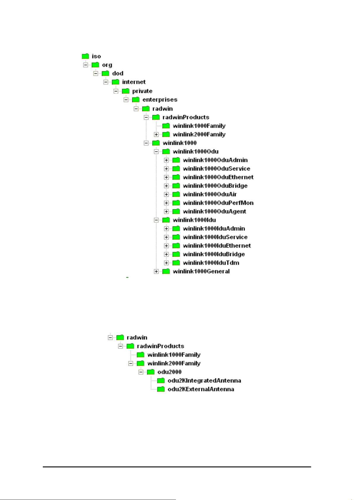
Private MIB Structure Appendix G
Figure G-1: Top Level Sections of the private MIB
The products MIB section contains the definition of the Object IDs for the
two form factors of the ODU, Integrated Antenna and Connectorized
(referred in the MIB as external antenna):
The ODU MIB contains the sections: Admin, Service, Ethernet, Bridge, Air,
PerfMon and Agent.
The IDU MIB contains the sections: Admin, Service, Ethernet, Bridge and
TDM.
The general MIB include a single generic parameter that is used by all traps
as a trap description parameter.
RADWIN 1000/2000/5000 User ManualVersion 2.6.50p1 G-3
Page 89

MIB Parameters Appendix G
MIB Parameters
The following section describes all of the MIB parameters. The MIB parameters follow the following naming convention:
<winlink1000><Section 1>...<Section n><Parameter Name>
For each of the configuration and control parameters (parameters with
read-write access), the “Description” column describes when the new value
is effective. It is recommended that you perform the appropriate action to
make the values affective immediately after any change. Where a change is
required on both sides of the link, it is recommended that you change both
sides of the link first and then perform the action.
Supported Variables from the RFC 1213 MIB
Table G-1: Supported RFC 1213 Variables (Sheet 1 of 2)
Name OID Type
ifIndex
ifDescr .1.3.6.1.2.1.2.2.1.2 DisplayString RO A textual string containing information about the
ifType .1.3.6.1.2.1.2.2.1.3 Integer RO The type of interface, distinguished according to
ifSpeed .1.3.6.1.2.1.2.2.1.5 Gauge RO An estimate of the interface's current bandwidth in
ifPhysAddress .1.3.6.1.2.1.2.2.1.6 Phys-Address RO The interface's address at the protocol layer
ifAdminStatus .1.3.6.1.2.1.2.2.1.7 Integer RW The desired state of the interface. The testing(3)
ifOperStatus .1.3.6.1.2.1.2.2.1.8 Integer RO The current operational state of the interface. The
ifInOctets .1.3.6.1.2.1.2.2.1.10.x Counter RO The total number of octets received on the
ifInUcastPkts .1.3.6.1.2.1.2.2.1.11.x Counter RO The number of subnetwork-unicast packets
ifInNUcastPkts .1.3.6.1.2.1.2.2.1.12.x Counter RO The number of non-unicast (i.e., subnetwork-
.1.3.6.1.2.1.2.2.1.1.x
a
Integer RO A unique value for each interface.Its value ranges
Access
Description
between 1 and the value of ifNumber.The value for
each interface must remain constant at least from
one re-initialization of the entity's network
management system to the next re-initialization.
interface.This string should include the name of
the manufacturer, the product name and the
version of the hardware interface.
the physical/link protocol(s) immediately `below'
the network layer in the protocol stack.
bits per second.For interfaces which do not vary in
bandwidth or for those where no accurate
estimation can be made, this object should ontain
the nominal bandwidth.
immediately `below' the network layer in the
protocol stack. For interfaces which do not have
such an address (e.g., a serial line), this object
should contain an octet string of zero length.
state indicates that no operational packets can be
passed.
testing(3) state indicates that no operational
packets can be passed.
interface, including framing characters.
delivered to a higher-layer protocol.
broadcast or subnetwork-multicast) packets
delivered to a higher-layer protocol.
RADWIN 1000/2000/5000 User ManualVersion 2.6.50p1 G-4
Page 90

MIB Parameters Appendix G
Table G-1: Supported RFC 1213 Variables (Sheet 2 of 2)
Name OID Type
ifInErrors .1.3.6.1.2.1.2.2.1.14.x Counter RO The number of inbound packets that contained
ifOutOctets .1.3.6.1.2.1.2.2.1.16.x Counter RO The total number of octets transmitted out of the
ifOutUcastPkts .1.3.6.1.2.1.2.2.1.17.x Counter RO The total number of packets that higher-level
ifOutNUcastPkts .1.3.6.1.2.1.2.2.1.18.x Counter RO The total number of packets that higher-level
a. x is the interface ID
Access
Description
errors preventing them from being deliverable to a
higher-layer protocol.
interface, including framing characters.
protocols requested be transmitted to a
subnetwork-unicast address, including those that
were discarded or not sent.
protocols requested be transmitted to a nonunicast (i.e., a subnetwork-broadcast or
subnetwork-multicast) address, including those
that were discarded or not sent.
MIB Parameters
Table G-2: Private MIB Parameters (Sheet 1 of 14)
Name OID Type
Access
Description
winlink1000OduAdmProductType 1.3.6.1.4.1.4458.1000.1.1.1 DisplayString RO ODU configuration description.
winlink1000OduAdmHwRev 1.3.6.1.4.1.4458.1000.1.1.2 DisplayString RO ODU Hardware Version.
winlink1000OduAdmSwRev 1.3.6.1.4.1.4458.1000.1.1.3 DisplayString RO ODU Software Version.
winlink1000OduAdmLinkName 1.3.6.1.4.1.4458.1000.1.1.4 DisplayString RW Link Name. A change is effective immediately.
winlink1000OduAdmResetCmd 1.3.6.1.4.1.4458.1000.1.1.5 Integer RW Reset Command. A set command with a value of 3
will cause a device reset. The read value is always
0.
winlink1000OduAdmAddres 1.3.6.1.4.1.4458.1000.1.1.6 IpAddress RW ODU IP address. A change is effective after reset.
winlink1000OduAdmMask 1.3.6.1.4.1.4458.1000.1.1.7 IpAddress RW ODU Subnet Mask. A change is effective after
winlink1000OduAdmGateway 1.3.6.1.4.1.4458.1000.1.1.8 IpAddress RW ODU default gateway. A change is effective after
winlink1000OduAdmBroadcast 1.3.6.1.4.1.4458.1000.1.1.10 Integer RW This parameter is reserved for the Manager
winlink1000OduAdmHostsTable N/A Trap destinations table. Each trap destination is
winlink1000OduAdmHostsEntry N/A Trap destinations table entry.
winlink1000OduAdmHostsIndex RO Trap destinations table index.
winlink1000OduAdmHostsIp 1.3.6.1.4.1.4458.1000.1.1.12.1.2 IpAddress RW Trap destination IP address. A change is effective
The parameter is kept for backward compatibility.
Using the alternative parameter:
winlink1000OduAdmIpParamsCnfg is
recommended.
reset. The parameter is kept for backward
compatibility. Using the alternative parameter:
winlink1000OduAdmIpParamsCnfg is
recommended.
reset. The parameter is kept for backward
compatibility. Using the alternative parameter:
winlink1000OduAdmIpParamsCnfg is
recommended.
application provided with the product.
defined by an IP address and a UDP port. Up to 10
addresses can be configured.
immediately.
RADWIN 1000/2000/5000 User ManualVersion 2.6.50p1 G-5
Page 91

MIB Parameters Appendix G
Table G-2: Private MIB Parameters (Sheet 2 of 14)
Name OID Type
winlink1000OduAdmHostsPort 1.3.6.1.4.1.4458.1000.1.1.12.1.3 Integer RW UDP port of the trap destination. A change is
winlink1000OduBuzzerAdminState 1.3.6.1.4.1.4458.1000.1.1.13 Integer RW This parameter controls the activation of the
winlink1000OduProductId 1.3.6.1.4.1.4458.1000.1.1.14 DisplayString RO This parameter is reserved for the Manager
winlink1000OduReadCommunity 1.3.6.1.4.1.4458.1000.1.1.15 DisplayString RW Read Community String. This parameter always
winlink1000OduReadWriteCommunity 1.3.6.1.4.1.4458.1000.1.1.16 DisplayString RW Read/Write Community String. This parameter
winlink1000OduTrapCommunity 1.3.6.1.4.1.4458.1000.1.1.17 DisplayString RW Trap Community String. This parameter is used by
winlink1000OduAdmSnmpAgentVersion 1.3.6.1.4.1.4458.1000.1.1.18 Integer RO Major version of the SNMP agent.
winlink1000OduAdmRemoteSiteName 1.3.6.1.4.1.4458.1000.1.1.19 DisplayString RO Remote site name. Returns the same value as
winlink1000OduAdmSnmpAgentMinorVe
rsion
winlink1000OduAdmLinkPassword 1.3.6.1.4.1.4458.1000.1.1.21 DisplayString RW Link Password. This parameter always returns
winlink1000OduAdmSiteLinkPassword 1.3.6.1.4.1.4458.1000.1.1.22 DisplayString RW Site Link Password. This parameter always returns
winlink1000OduAdmDefaultPassword 1.3.6.1.4.1.4458.1000.1.1.23 Integer RO This parameter indicates if the current Link
winlink1000OduAdmConnectionType 1.3.6.1.4.1.4458.1000.1.1.24 Integer RO This parameter indicates if the Manager
winlink1000OduAdmBackToFactorySetti
ngsCmd
winlink1000OduAdmIpParamsCnfg 1.3.6.1.4.1.4458.1000.1.1.26 DisplayString RW ODU IP address Configuration. The format is:
winlink1000OduAdmVlanID 1.3.6.1.4.1.4458.1000.1.1.27 Integer RW VLAN ID. Valid values are 1 to 4094. Initial value is
winlink1000OduAdmVlanPriority 1.3.6.1.4.1.4458.1000.1.1.28 Integer RW VLAN Priority. 0 is lowest priority 7 is highest
winlink1000OduAdmSN 1.3.6.1.4.1.4458.1000.1.1.29 DisplayString RO IDU Serial Number
winlink1000OduSrvMode 1.3.6.1.4.1.4458.1000.1.2.1 Integer RW System mode. The only value that can be set is
1.3.6.1.4.1.4458.1000.1.1.20 Integer RO Minor version of the SNMP agent.
1.3.6.1.4.1.4458.1000.1.1.25 Integer RW Back to factory settings Command. A change is
Access
Description
effective immediately.
buzzer while the unit is in install mode. A change is
effective immediately. The valid values are:
disabled (0) enabled (1).
application provided with the product.
returns ***** when retrieving its value. It is used by
the Manager application to change the Read
Community String. The SNMP agent accepts only
encrypted values.
always returns ***** when retrieving its value. It is
used by the Manager application to change the
Read/Write Community String. The SNMP agent
accepts only encrypted values.
the Manager application to change the Trap
Community String. The SNMP agent accepts only
encrypted values.
sysLocation parameter of the remote site.
***** when retrieving its value. It is used by the
Manager application to change the Link Password.
The SNMP agent accepts only encrypted values.
***** when retrieving its value. It is used by the
Manager application to change the Link Password
of the site. The SNMP agent accepts only
encrypted values.
Password is the default password.
application is connected to the local ODU or to the
remote ODU over the air. A value of 'unknown'
indicates community string mismatch.
effective after reset. The read value is always 0.
<IP_Address>|<Subnet_Mask>|<Default_Gatewa
y>|
0 meaning VLAN unaware.
priority.
installMode; normalMode reserved to the Manager
application provided with the product. A change is
effective after link re-synchronization.
RADWIN 1000/2000/5000 User ManualVersion 2.6.50p1 G-6
Page 92

MIB Parameters Appendix G
Table G-2: Private MIB Parameters (Sheet 3 of 14)
Name OID Type
winlink1000OduSrvBridging 1.3.6.1.4.1.4458.1000.1.2.3 Integer RO Bridging Mode. Valid values are: disabled (0)
winlink1000OduEthernetRemainingRate 1.3.6.1.4.1.4458.1000.1.3.1 Integer RO Current Ethernet bandwidth in bps.
winlink1000OduEthernetIfTable N/A ODU Ethernet Interface table.
winlink1000OduEthernetIfEntry N/A ODU Ethernet Interface table entry.
winlink1000OduEthernetIfIndex 1.3.6.1.4.1.4458.1000.1.3.2.1.1 Integer RO ODU Ethernet Interface Index.
winlink1000OduEthernetIfAddress 1.3.6.1.4.1.4458.1000.1.3.2.1.5 DisplayString RO ODU MAC address.
winlink1000OduEthernetIfAdminStatus 1.3.6.1.4.1.4458.1000.1.3.2.1.6 Integer RW Required state of the interface.
winlink1000OduEthernetIfOperStatus 1.3.6.1.4.1.4458.1000.1.3.2.1.7 Integer RO Current operational state of the interface.
winlink1000OduEthernetIfFailAction 1.3.6.1.4.1.4458.1000.1.3.2.1.8 Integer RW Failure action of the interface.
winlink1000OduEthernetNumOfPorts 1.3.6.1.4.1.4458.1000.1.3.3 Integer RO Number of ODU network interfaces.
winlink1000OduBridgeBasePortTable N/A ODU Bridge Ports table.
winlink1000OduBridgeBasePortEntry N/A ODU Bridge Ports table entry.
winlink1000OduBridgeBasePortIndex RO ODU Bridge Port Number.
winlink1000OduBridgeBaseIfIndex RO IfIndex corresponding to ODU Bridge port.
winlink1000OduBridgeTpMode 1.3.6.1.4.1.4458.1000.1.4.4.101 Integer RW ODU bridge mode. A change is effective after
winlink1000OduBridgeTpPortTable N/A ODU Transparent Bridge Ports table.
winlink1000OduBridgeTpPortEntry N/A ODU Transparent Bridge Ports table entry.
winlink1000OduBridgeTpPortIndex RO ODU Transparent Bridge Port Number.
winlink1000OduBridgeTpPortInFrames 1.3.6.1.4.1.4458.1000.1.4.4.3.1.3 Counter RO Number of frames received by this port.
winlink1000OduBridgeTpPortOutFrames 1.3.6.1.4.1.4458.1000.1.4.4.3.1.4 Counter RO Number of frames transmitted by this port.
winlink1000OduBridgeTpPortInBytes 1.3.6.1.4.1.4458.1000.1.4.4.3.1.101Counter RO Number of bytes received by this port.
Access
Description
enabled (1).
reset. Valid values: hubMode (0) bridgeMode (1).
winlink1000OduBridgeTpPortOutBytes 1.3.6.1.4.1.4458.1000.1.4.4.3.1.102Counter RO Number of bytes transmitted by this port.
winlink1000OduAirFreq 1.3.6.1.4.1.4458.1000.1.5.1 Integer RW Installation Center Frequency. Valid values are
product dependent. A change is effective after link
re-synchronization.
winlink1000OduAirDesiredRate 1.3.6.1.4.1.4458.1000.1.5.2 Integer RW Deprecated parameter actual behavior is read-
only. Required Air Rate. For Channel Bandwidth of
20 10 5 MHz divide the value by 1 2 4 respectively.
winlink1000OduAirSSID 1.3.6.1.4.1.4458.1000.1.5.3 DisplayString RW Reserved for the Manager application provided
winlink1000OduAirTxPower 1.3.6.1.4.1.4458.1000.1.5.4 Integer RW Required Transmit power in dBm . This is a
winlink1000OduAirSesState 1.3.6.1.4.1.4458.1000.1.5.5 Integer RO Current Link State. The value is active (3) during
winlink1000OduAirMstrSlv 1.3.6.1.4.1.4458.1000.1.5.6 Integer RO This parameter indicates if the device was
winlink1000OduAirResync 1.3.6.1.4.1.4458.1000.1.5.8 Integer RW Setting this parameter to 1 will cause the link to
winlink1000OduAirRxPower 1.3.6.1.4.1.4458.1000.1.5.9.1 Integer RO Received Signal Strength in dBm.
winlink1000OduAirTotalFrames 1.3.6.1.4.1.4458.1000.1.5.9.2 Counter RO Total Number of received radio frames.
winlink1000OduAirBadFrames 1.3.6.1.4.1.4458.1000.1.5.9.3 Counter RO Total number of received radio frames with CRC
winlink1000OduAirCurrentRate 1.3.6.1.4.1.4458.1000.1.5.9.4 Integer RO Deprecated parameter. Actual rate of the air
with the product.
nominal value while the actual transmit power
includes additional attenuation. The min and max
values are product specific. A change is effective
immediately.
normal operation.
automatically selected into the radio link master or
slave. The value is undefined if there is no link.
restart the synchronization process.
error.
interface in Mbps. For Channel Bandwidth of 20 10
5 MHz divide the value by 1 2 4 respectively.
RADWIN 1000/2000/5000 User ManualVersion 2.6.50p1 G-7
Page 93

MIB Parameters Appendix G
Table G-2: Private MIB Parameters (Sheet 4 of 14)
Name OID Type
winlink1000OduAirCurrentRateIdx 1.3.6.1.4.1.4458.1000.1.5.9.5 Integer RO Index of current air rate.
winlink1000OduAirTxPower36 1.3.6.1.4.1.4458.1000.1.5.10 Integer RW Deprecated parameter. Actual behavior is read-
winlink1000OduAirTxPower48 1.3.6.1.4.1.4458.1000.1.5.11 Integer RW Deprecated parameter. Actual behavior is read-
winlink1000OduAirCurrentTxPower 1.3.6.1.4.1.4458.1000.1.5.12 Integer RO Current Transmit Power in dBm. This is a nominal
winlink1000OduAirMinFrequency 1.3.6.1.4.1.4458.1000.1.5.13 Integer RO Minimum center frequency in MHz.
winlink1000OduAirMaxFrequency 1.3.6.1.4.1.4458.1000.1.5.14 Integer RO Maximum center frequency in MHz.
winlink1000OduAirFreqResolution 1.3.6.1.4.1.4458.1000.1.5.15 Integer RO Center Frequency resolution. Measured in MHz if
winlink1000OduAirCurrentFreq 1.3.6.1.4.1.4458.1000.1.5.16 Integer RO Current Center Frequency. Measured in MHz if
winlink1000OduAirNumberOfChannels 1.3.6.1.4.1.4458.1000.1.5.17 Integer RO Number of channels that can be used.
winlink1000OduAirChannelsTable N/A Table of channels used by automatic channels
winlink1000OduAirChannelsEntry N/A ACS channels table entry.
winlink1000OduAirChannelsIndex 1.3.6.1.4.1.4458.1000.1.5.18.1.1 Integer RO Channel Index.
winlink1000OduAirChannelsFrequency 1.3.6.1.4.1.4458.1000.1.5.18.1.2 Integer RO Channel frequency in MHz.
winlink1000OduAirChannelsOperState 1.3.6.1.4.1.4458.1000.1.5.18.1.3 Integer RW Channel state. Can be set by the user. Automatic
winlink1000OduAirChannelsAvail 1.3.6.1.4.1.4458.1000.1.5.18.1.4 Integer RO Channel state. Product specific and cannot be
winlink1000OduAirDfsState 1.3.6.1.4.1.4458.1000.1.5.19 Integer RO Radar detection state. Valid values: disabled (0)
winlink1000OduAirAutoChannelSelection
State
winlink1000OduAirEnableTxPower 1.3.6.1.4.1.4458.1000.1.5.21 Integer RO Indicating Transmit power configuration enabled or
winlink1000OduAirMinTxPower 1.3.6.1.4.1.4458.1000.1.5.22 Integer RO Minimum Transmit power in dBm.
winlink1000OduAirMaxTxPowerTable N/A Table of Maximum transmit power per air rate in
winlink1000OduAirMaxTxPowerEntry N/A Maximum Transmit power table entry.
winlink1000OduAirMaxTxPowerIndex 1.3.6.1.4.1.4458.1000.1.5.23.1.1 Integer RO Air interface rate index.
winlink1000OduAirMaxTxPower 1.3.6.1.4.1.4458.1000.1.5.23.1.2 Integer RO Maximum Transmit power in dBm.
winlink1000OduAirChannelBandwidth 1.3.6.1.4.1.4458.1000.1.5.24 Integer RW Channel bandwidth in KHz. A change is effective
winlink1000OduAirChannelBWTable N/A Channel Bandwidths table.
winlink1000OduAirChannelBWEntry N/A Channel Bandwidth table entry.
winlink1000OduAirChannelBWIndex 1.3.6.1.4.1.4458.1000.1.5.25.1.1 Integer RO Channel Bandwidth index.
winlink1000OduAirChannelBWAvail 1.3.6.1.4.1.4458.1000.1.5.25.1.2 Integer RO Channel Bandwidth availability product specific.
1.3.6.1.4.1.4458.1000.1.5.20 Integer RO Deprecated parameter. Indicating Automatic
Access
Description
only.
only.
value while the actual transmit power includes
additional attenuation.
value < 100 otherwise in KHz.
center frequency resolution value < 100 otherwise
in KHz.
selection (ACS).
Channel Selection uses channels that are
AirChannelsOperState enabled and
AirChannelsAvail enabled. A change is effective
after link re-synchronization. Valid values: disabled
(0) enabled (1).
changed by the user. Automatic Channel Selection
uses channels that are AirChannelsOperState
enabled and AirChannelsAvail enabled. Valid
values: disabled (0) enabled (1).
enabled (1).
Channel Selection availability at current channel
bandwidth. Valid values: disabled (0) enabled (1).
disabled.
dBm.
after reset.
Options are: Not supported supported with manual
channel selection supported with Automatic
Channel Selection.
RADWIN 1000/2000/5000 User ManualVersion 2.6.50p1 G-8
Page 94

MIB Parameters Appendix G
Table G-2: Private MIB Parameters (Sheet 5 of 14)
Name OID Type
winlink1000OduAirRFD 1.3.6.1.4.1.4458.1000.1.5.26 Integer RO Current radio frame duration in microseconds.
winlink1000OduAirRatesTable N/A Air Rate indexes table for current channel
winlink1000OduAirRatesEntry N/A Air Rate indexes table entry.
winlink1000OduAirRatesIndex 1.3.6.1.4.1.4458.1000.1.5.27.1.1 Integer RO Air Rate index.
winlink1000OduAirRatesAvail 1.3.6.1.4.1.4458.1000.1.5.27.1.2 Integer RO Air Rate availability depending on air interface
winlink1000OduAirDesiredRateIdx 1.3.6.1.4.1.4458.1000.1.5.28 Integer RW Required Air Rate index. 0 reserved for Adaptive
winlink1000OduAirLinkDistance 1.3.6.1.4.1.4458.1000.1.5.29 Integer RO Link distance in meters. A value of -1 indicates an
winlink1000OduAirLinkWorkingMode 1.3.6.1.4.1.4458.1000.1.5.30 Integer RO Link working mode as a result of comparing
winlink1000OduAirMajorLinkIfVersion 1.3.6.1.4.1.4458.1000.1.5.31 Integer RO Major link interface version
winlink1000OduAirMinorLinkIfVersion 1.3.6.1.4.1.4458.1000.1.5.32 Integer RO Minor link interface version
winlink1000OduAirHssDesiredOpState 1.3.6.1.4.1.4458.1000.1.5.40.1 Integer RW Required Hub Site Synchronization operating
winlink1000OduAirHssCurrentOpState 1.3.6.1.4.1.4458.1000.1.5.40.2 Integer RO Current Hub Site Synchronization operating state.
winlink1000OduAirHssSyncStatus 1.3.6.1.4.1.4458.1000.1.5.40.3 Integer RO Hub Site Synchronization sync status.
winlink1000OduAirHssExtPulseStatus 1.3.6.1.4.1.4458.1000.1.5.40.4 Integer RO Hub Site Synchronization external pulse detection
winlink1000OduAirHssExtPulseType 1.3.6.1.4.1.4458.1000.1.5.40.5 Integer RO Hub Site Synchronization external pulse type.
winlink1000OduAirHssDesiredExtPulseT
ype
winlink1000OduAirHssRfpTable N/A ODU Radio Frame Patterns (RFP) Table.
winlink1000OduAirHssRfpEntry N/A ODU RFP Table entry.
winlink1000OduAirHssRfpIndex 1.3.6.1.4.1.4458.1000.1.5.40.7.1.1 Integer RO ODU RFP Table index. The index represent the
winlink1000OduAirHssRfpEthChannelB
W5MHz
winlink1000OduAirHssRfpTdmChannelB
W5MHz
winlink1000OduAirHssRfpEthChannelB
W10MHz
winlink1000OduAirHssRfpTdmChannelB
W10MHz
winlink1000OduAirHssRfpEthChannelB
W20MHz
winlink1000OduAirHssRfpTdmChannelB
W20MHz
1.3.6.1.4.1.4458.1000.1.5.40.6 Integer RW Hub Site Synchronization required external pulse
1.3.6.1.4.1.4458.1000.1.5.40.7.1.2 Integer RO Represents the compatibility of Ethernet service
1.3.6.1.4.1.4458.1000.1.5.40.7.1.3 Integer RO Represents the compatibility of TDM service under
1.3.6.1.4.1.4458.1000.1.5.40.7.1.4 Integer RO Represents the compatibility of Ethernet service
1.3.6.1.4.1.4458.1000.1.5.40.7.1.5 Integer RO Represents the compatibility of TDM service under
1.3.6.1.4.1.4458.1000.1.5.40.7.1.6 Integer RO Represents the compatibility of Ethernet service
1.3.6.1.4.1.4458.1000.1.5.40.7.1.7 Integer RO Represents the compatibility of TDM service under
Access
Description
bandwidth.
conditions.
Rate. A change is effective immediately after Set
operation to the master side while the link is up.
illegal value and is also used when a link is not
established.
versions of both sides of the link. Possible modes
are: Unknown - no link Normal - versions on both
sides are identical with full compatibility with
restricted compatibility or versions on both sides
are different with software upgrade or versions
incompatibility.
state.
status.
type. Valid values for read write: {typeA(2)
typeB(3) typeC(4) typeD(5)}. Valid value for read
only: {notApplicable(1)}.
Radio Frame Pattern: typeA(2) typeB(3) typeC(4)
typeD(5).
under Channel BW of 5MHz in the specific Radio
Frame Pattern.
Channel BW of 5MHz in the specific Radio Frame
Pattern.
under Channel BW of 10MHz in the specific Radio
Frame Pattern.
Channel BW of 10MHz in the specific Radio Frame
Pattern.
under Channel BW of 20MHz in the specific Radio
Frame Pattern.
Channel BW of 20MHz in the specific Radio Frame
Pattern.
RADWIN 1000/2000/5000 User ManualVersion 2.6.50p1 G-9
Page 95

MIB Parameters Appendix G
Table G-2: Private MIB Parameters (Sheet 6 of 14)
Name OID Type
winlink1000OduAirLockRemote 1.3.6.1.4.1.4458.1000.1.5.41 Integer RW This parameter enables locking the link with a
winlink1000OduAirAntennaGain 1.3.6.1.4.1.4458.1000.1.5.42 Integer RW Current Antenna Gain in 0.1 dBi resolution. User
winlink1000OduAirFeederLoss 1.3.6.1.4.1.4458.1000.1.5.43 Integer RW Current Feeder Loss in 0.1 dBm resolution. User
winlink1000OduAirMaxAntennaGain 1.3.6.1.4.1.4458.1000.1.5.44 Integer RO Maximum allowed Antenna Gain in 0.1 dBi
winlink1000OduAirMinAntennaGain 1.3.6.1.4.1.4458.1000.1.5.45 Integer RO Minimum allowed Antenna Gain in 0.1 dBi
winlink1000OduAirMaxEIRP 1.3.6.1.4.1.4458.1000.1.5.46 Integer RO Maximum EIRP value as defined by regulation in
winlink1000OduAirAntennaGainConfigSu
pport
winlink1000OduAirAntennaType 1.3.6.1.4.1.4458.1000.1.5.48 Integer RW External Antenna Type: Monopolar or Bipolar.
winlink1000OduAirRssBalance 1.3.6.1.4.1.4458.1000.1.5.49 Integer RO RSS balance. Relation between RSS in radio 1
winlink1000OduAirTotalTxPower 1.3.6.1.4.1.4458.1000.1.5.50 Integer RO Total Transmit Power in dBm. This is a nominal
winlink1000OduPerfMonCurrTable N/A This table defines/keeps the counters of the
winlink1000OduPerfMonCurrEntry N/A This is an entry in the Current Interval Table.
winlink1000OduPerfMonCurrUAS 1.3.6.1.4.1.4458.1000.1.6.1.1.1 Gauge RO The current number of Unavailable Seconds
winlink1000OduPerfMonCurrES 1.3.6.1.4.1.4458.1000.1.6.1.1.2 Gauge RO Current number of Errored Seconds starting from
winlink1000OduPerfMonCurrSES 1.3.6.1.4.1.4458.1000.1.6.1.1.3 Gauge RO Current number of Severely Errored Seconds
winlink1000OduPerfMonCurrBBE 1.3.6.1.4.1.4458.1000.1.6.1.1.4 Gauge RO Current number of Background Block Errors
winlink1000OduPerfMonCurrIntegrity 1.3.6.1.4.1.4458.1000.1.6.1.1.5 Integer RO Indicates the integrity of the entry.
winlink1000OduPerfMonIntervalTable N/A This table defines/keeps the counters of the
winlink1000OduPerfMonIntervalEntry N/A This is an entry in the Interval Table.
winlink1000OduPerfMonIntervalIdx RO This table is indexed per interval number. Each
winlink1000OduPerfMonIntervalUAS RO The current number of Unavailable Seconds per
winlink1000OduPerfMonIntervalES RO Current number of Errored Seconds per interval.
winlink1000OduPerfMonIntervalSES RO Current number of Severely Errored Seconds per
winlink1000OduPerfMonIntervalBBE RO Current number of Background Block Errors per
winlink1000OduPerfMonIntervalIntegrity RO Indicates the integrity of the entry per interval.
1.3.6.1.4.1.4458.1000.1.5.47 Integer RO Antenna Gain Configurability options are product
Access
Description
specific ODU. The following values can be set:
Unlock (default) - The ODU is not locked on a
specific remote ODU. Unlock can only be
performed when the link is not connected. Lock The ODU is locked on a specific remote ODU.
Lock can only be performed when the link is
active.
defined value in case of external antenna. Legal
range:
MinAntennaGain<AntennaGain<MaxAntennaGain
.
defined value in case of external antenna.
resolution.
resolution.
0.1 dBm resolution.
specific: supported not supported.
and RSS in radio 2.
value While the actual transmit power includes
additional attenuation.
current 15 min interval.
starting from the present 15 minutes period.
the present 15 minutes period.
starting from the present 15 minutes period.
starting from the present 15 minutes period.
current 15 min interval.
interval is of 15 minutes and the oldest is 96.
interval.
interval.
interval.
RADWIN 1000/2000/5000 User ManualVersion 2.6.50p1 G-10
Page 96

MIB Parameters Appendix G
Table G-2: Private MIB Parameters (Sheet 7 of 14)
Name OID Type
winlink1000OduPerfMonDayTable N/A This table defines/keeps the counters of the
winlink1000OduPerfMonDayEntry N/A This is an entry in the Days Table.
winlink1000OduPerfMonDayIdx RO This table is indexed per interval number. Each
winlink1000OduPerfMonDayUAS RO The current number of Unavailable Seconds per
winlink1000OduPerfMonDayES RO Current number of Errored Seconds per interval of
winlink1000OduPerfMonDaySES RO Current number of Severely Errored Seconds per
winlink1000OduPerfMonDayBBE RO Current number of Background Block Errors per
winlink1000OduPerfMonDayIntegrity RO Indicates the integrity of the entry per interval of 24
winlink1000OduPerfMonAirCurrTable N/A This table defines/keeps the counters of the
winlink1000OduPerfMonAirCurrEntry N/A This is an entry in the Current Interval Table.
winlink1000OduPerfMonAirCurrMinRSL 1.3.6.1.4.1.4458.1000.1.6.4.1.1 Integer RO Current Min Received Level Reference starting
winlink1000OduPerfMonAirCurrMaxRSL 1.3.6.1.4.1.4458.1000.1.6.4.1.2 Integer RO Current Max Received Level Reference starting
winlink1000OduPerfMonAirCurrRSLThre
sh1Exceed
winlink1000OduPerfMonAirCurrRSLThre
sh2Exceed
winlink1000OduPerfMonAirCurrMinTSL 1.3.6.1.4.1.4458.1000.1.6.4.1.5 Integer RO Current Min Transmit Signal Level starting from
winlink1000OduPerfMonAirCurrMaxTSL 1.3.6.1.4.1.4458.1000.1.6.4.1.6 Integer RO Current Max Transmit Signal Level starting from
winlink1000OduPerfMonAirCurrTSLThre
sh1Exceed
winlink1000OduPerfMonAirCurrBBERThr
esh1Exceed
winlink1000OduPerfMonAirIntervalTable N/A This table defines/keeps the counters of the
winlink1000OduPerfMonAirIntervalEntry N/A This is an entry in the Interval Table.
winlink1000OduPerfMonAirIntervalIdx RO This table is indexed per interval number. Each
winlink1000OduPerfMonAirIntervalMinRS
L
winlink1000OduPerfMonAirIntervalMaxR
SL
winlink1000OduPerfMonAirIntervalRSLT
hresh1Exceed
winlink1000OduPerfMonAirIntervalRSLT
hresh2Exceed
winlink1000OduPerfMonAirIntervalMinTS
L
1.3.6.1.4.1.4458.1000.1.6.4.1.3 Gauge RO Number of seconds Receive Signal Level
1.3.6.1.4.1.4458.1000.1.6.4.1.4 Gauge RO Number of seconds Receive Signal Level
1.3.6.1.4.1.4458.1000.1.6.4.1.7 Gauge RO Number of seconds Transmit Signal Level
1.3.6.1.4.1.4458.1000.1.6.4.1.8 Gauge RO Number of seconds Background Block Error Ratio
Access
Description
current 15 min interval.
interval is of 24 hours and the oldest is 30.
interval of 24 hours.
24 hours.
interval of 24 hours.
interval of 24 hours.
hours.
current 15 min interval.
from the present 15 minutes period.
from the present 15 minutes period.
exceeded the RSL1 threshold in the last 15
minutes.
exceeded the RSL2 threshold in the last 15
minutes.
the present 15 minutes period.
the present 15 minutes period.
exceeded the TSL1 threshold in the last 15
minutes.
exceeded the BBER1 threshold in the last 15
minutes.
current 15 min interval.
interval is of 15 minutes and the oldest is 96.
RO Current Min Received Level Reference per
interval.
RO Current Max Received Level Reference per
interval.
RO Number of seconds Receive Signal Level
exceeded the RSL1 threshold per interval.
Number of seconds Receive Signal Level
exceeded the RSL2 threshold ACCESS read-only
per interval.
RO Current Min Transmit Signal Level per interval.
RADWIN 1000/2000/5000 User ManualVersion 2.6.50p1 G-11
Page 97

MIB Parameters Appendix G
Table G-2: Private MIB Parameters (Sheet 8 of 14)
Name OID Type
winlink1000OduPerfMonAirIntervalMaxT
SL
winlink1000OduPerfMonAirIntervalTSLTh
resh1Exceed
winlink1000OduPerfMonAirIntervalBBER
Thresh1Exceed
winlink1000OduPerfMonAirDayTable N/A This table defines/keeps the counters of the
winlink1000OduPerfMonAirDayEntry N/A This is an entry in the Days Table.
winlink1000OduPerfMonAirDayIdx RO This table is indexed per Day number. Each Day is
winlink1000OduPerfMonAirDayMinRSL RO Current Min Received Level Reference per Day.
winlink1000OduPerfMonAirDayMaxRSL RO Current Max Received Level Reference per Day.
winlink1000OduPerfMonAirDayRSLThres
h1Exceed
winlink1000OduPerfMonAirDayRSLThres
h2Exceed
winlink1000OduPerfMonAirDayMinTSL RO Current Min Transmit Signal Level per Day.
winlink1000OduPerfMonAirDayMaxTSL RO Current Max Transmit Signal Level per Day.
winlink1000OduPerfMonAirDayTSLThres
h1Exceed
winlink1000OduPerfMonAirDayBBERThr
esh1Exceed
winlink1000OduPerfMonEthCurrTable N/A This table defines/keeps the counters of the
winlink1000OduPerfMonEthCurrEntry N/A This is an entry in the Current Interval Table.
winlink1000OduPerfMonEthCurrRxMBytes1.3.6.1.4.1.4458.1000.1.6.7.1.1 Gauge RO Current RX Mega Bytes starting from the present
winlink1000OduPerfMonEthCurrTxMBytes1.3.6.1.4.1.4458.1000.1.6.7.1.2 Gauge RO Current Transmit Mega Bytes starting from the
winlink1000OduPerfMonEthIntervalTable N/A This table defines/keeps the counters of the
winlink1000OduPerfMonEthIntervalEntry N/A This is an entry in the Interval Table.
winlink1000OduPerfMonEthIntervalIdx RO This table is indexed per interval number. Each
winlink1000OduPerfMonEthIntervalRxMB
ytes
winlink1000OduPerfMonEthIntervalTxMB
ytes
winlink1000OduPerfMonEthDayTable N/A This table defines/keeps the counters of the
winlink1000OduPerfMonEthDayEntry N/A This is an entry in the Days Table.
winlink1000OduPerfMonEthDayIdx RO This table is indexed per Day number. Each Day is
winlink1000OduPerfMonEthDayRxMByte
s
winlink1000OduPerfMonEthDayTxMByte
s
winlink1000OduPerfMonTdmCurrTable N/A This table defines/keeps the counters of the
winlink1000OduPerfMonTdmCurrEntry N/A This is an entry in the Current Interval Table.
Access
Description
RO Current Max Transmit Signal Level per interval.
RO Number of seconds Transmit Signal Level
exceeded the TSL1 threshold per interval.
RO Number of seconds Background Block Error Ratio
exceeded the BBER1 threshold per interval.
current 15 min interval.
of 15 minutes and the oldest is 96.
RO Number of seconds Receive Signal Level
exceeded the RSL1 threshold per Day.
RO Number of seconds Receive Signal Level
exceeded the RSL2 threshold per Day.
RO Number of seconds Transmit Signal Level
exceeded the TSL1 threshold per Day.
RO Number of seconds Background Block Error Ratio
exceeded the BBER1 threshold per Day.
current 15 min interval.
15 minutes period.
present 15 minutes period.
current 15 min interval.
interval is of 15 minutes and the oldest is 96.
RO Current RX Mega Bytes per interval.
RO Current Transmit Mega Bytes per interval.
current 15 min interval.
of 15 minutes and the oldest is 96.
RO Current RX Mega Bytes per day.
RO Current Transmit Mega Bytes per day.
current 15 min interval.
RADWIN 1000/2000/5000 User ManualVersion 2.6.50p1 G-12
Page 98

MIB Parameters Appendix G
Table G-2: Private MIB Parameters (Sheet 9 of 14)
Name OID Type
winlink1000OduPerfMonTdmCurrActiveS
econds
winlink1000OduPerfMonTdmIntervalTabl
e
winlink1000OduPerfMonTdmIntervalEntr
y
winlink1000OduPerfMonTdmIntervalIdx RO This table is indexed per interval number. Each
winlink1000OduPerfMonTdmIntervalActiv
eSeconds
winlink1000OduPerfMonTdmDayTable N/A This table defines/keeps the counters of the
winlink1000OduPerfMonTdmDayEntry N/A This is an entry in the Days Table.
winlink1000OduPerfMonTdmDayIdx RO This table is indexed per Day number. Each Day is
winlink1000OduPerfMonTdmDayActiveS
econds
winlink1000OduPerfMonTxThresh1 1.3.6.1.4.1.4458.1000.1.6.20 Integer RW When the Transmit power exceeds this threshold a
winlink1000OduPerfMonRxThresh1 1.3.6.1.4.1.4458.1000.1.6.21 Integer RW When the RX power exceeds this threshold a
winlink1000OduPerfMonRxThresh2 1.3.6.1.4.1.4458.1000.1.6.22 Integer RW When the RX power exceeds this threshold a
winlink1000OduPerfMonBBERThresh1 1.3.6.1.4.1.4458.1000.1.6.23 Integer RW When the BBER exceeds this threshold a
winlink1000OduAgnGenAddTrapExt 1.3.6.1.4.1.4458.1000.1.7.1.1 Integer RW If 'yes' is chosen the ifIndex Unit Severity Time_T
winlink1000OduAgnNTPCfgTimeServerIP1.3.6.1.4.1.4458.1000.1.7.2.1 IpAddress RW IP address of the server from which the current
winlink1000OduAgnNTPCfgTimeOffsetFr
omUTC
1.3.6.1.4.1.4458.1000.1.7.2.2 Integer RW Offset from Coordinated Universal Time (minutes).
Access
Description
RO Parameter indicating whether the TDM service
was active. Under TDM backup link the parameter
indicates whether the backup link was active.
N/A This table defines/keeps the counters of the
current 15 min interval.
N/A This is an entry in the Interval Table.
interval is of 15 minutes and the oldest is 96.
RO Parameter indicating whether the TDM service
was active. Under TDM backup link the parameter
indicates whether the backup link was active.
current 15 min interval.
of 15 minutes and the oldest is 96.
RO Parameter indicating whether the TDM service
was active. Under TDM backup link the parameter
indicates whether the backup link was active.
performance monitoring TSL1 counter is
incremented.
performance monitoring RSL1 counter is
incremented.
performance monitoring RSL2 counter is
incremented.
performance monitoring BBER counter is
incremented. The units are 1/10 of a percent.
and Alarm Id from the
winlink1000OduAgnCurrAlarmTable will be bind to
the end of each private trap.
time is loaded.
Possible values: -1440..1440.
RADWIN 1000/2000/5000 User ManualVersion 2.6.50p1 G-13
Page 99

MIB Parameters Appendix G
Table G-2: Private MIB Parameters (Sheet 10 of 14)
Name OID Type
winlink1000OduAgnRealTimeAndDate 1.3.6.1.4.1.4458.1000.1.7.2.3 OctetString RW This parameter specifies the real time and date
winlink1000OduAgnCurrAlarmLastChange1.3.6.1.4.1.4458.1000.1.7.3.1 Integer RO This counter is initialized to 0 after a device reset
winlink1000OduAgnCurrAlarmTable N/A This table includes the currently active alarms.
winlink1000OduAgnCurrAlarmEntry N/A Entry containing the details of a currently RAISED
winlink1000OduAgnCurrAlarmCounter RO A running counter of active alarms. The counter is
winlink1000OduAgnCurrAlarmSeverity RO Current Alarm severity.
winlink1000OduAgnCurrAlarmId RO Unique Alarm Identifier (combines alarm type and
winlink1000OduAgnCurrAlarmIfIndex RO Interface Index where the alarm occurred. Alarms
winlink1000OduAgnCurrAlarmUnit RO Unit associated with the alarm.
winlink1000OduAgnCurrAlarmTrapID RO ID of the raised trap that was sent when this alarm
winlink1000OduAgnCurrAlarmTimeT RO Timestamp of this alarm. This number is in
winlink1000OduAgnCurrAlarmText RO Alarm display text (same as the text in the sent
winlink1000IduAdmProductType 1.3.6.1.4.1.4458.1000.2.1.1 DisplayString RO IDU configuration description.
winlink1000IduAdmHwRev 1.3.6.1.4.1.4458.1000.2.1.2 DisplayString RO IDU Hardware Revision.
winlink1000IduAdmSwRev 1.3.6.1.4.1.4458.1000.2.1.3 DisplayString RO IDU Software Revision.
winlink1000OduAdmNumOfExternalAlar
mIn
winlink1000OduAdmExternAlarmInTable N/A This is the External Alarm Inputs table.
winlink1000OduAdmExternAlarmInEntry N/A Entry containing the elements of a single External
1.3.6.1.4.1.4458.1000.2.1.4 Integer RO Indicates the number of currently available
Access
Description
Format 'YYYY-MM-DD HH:MM:SS'
(Hexadecimal).
A date-time specification:
field octets contents range
------ ------- ----------- ------- 1 1-2 year 0..65536
2 3 month 1..12
3 4 day 1.. 31
4 5 hour 0..23
5 6 minutes 0..59
6 7 seconds 0..60
(use 60 for leap-second)
7 8 deci-seconds 0..9
For example Tuesday May 26 1992 at 1:30:15
PM EDT would be displayed as:
07 c8 05 1a 0d 1e 0f 00
( 1992 -5 -26 13:30:15 )
and is incremented upon each change in the
winlink1000OduAgnCurrAlarmTable (either an
addition or removal of an entry).
When a RAISED trap is sent an alarm entry is
added to the table. When a CLEAR trap is sent the
entry is removed.
trap.
incremented for every new RAISED trap. It is
cleared after a device reset.
interface). The same AlarmId is used for RAISED
and CLEARED alarms.
that are not associated with a specific interface will
have the following value: 65535.
was raised.
seconds from Midnight January 1st 1970.
trap).
External Alarm Inputs.
Alarm Input.
RADWIN 1000/2000/5000 User ManualVersion 2.6.50p1 G-14
Page 100

MIB Parameters Appendix G
Table G-2: Private MIB Parameters (Sheet 11 of 14)
Name OID Type
winlink1000OduAdmExternAlarmInIndex 1.3.6.1.4.1.4458.1000.2.1.5.1.1 Integer RO This value indicates the index of the External
winlink1000OduAdmExternAlarmInText 1.3.6.1.4.1.4458.1000.2.1.5.1.2 DisplayString RW This field describes the External Alarm Input. It is
winlink1000OduAdmExternAlarmInAdmin
State
winlink1000OduAdmExternAlarmInStatus 1.3.6.1.4.1.4458.1000.2.1.5.1.4 Integer RO This value indicates the current status of the
winlink1000IduAdmSN 1.3.6.1.4.1.4458.1000.2.1.6 DisplayString RO Idu Serial Number
winlink1000IduSrvDesiredTrunks 1.3.6.1.4.1.4458.1000.2.2.2 Integer RW Required trunks bitmap. Note that the number of
winlink1000IduSrvServices 1.3.6.1.4.1.4458.1000.2.2.4 ObjectID RO This parameter is reserved to the Manager
winlink1000IduSrvActiveTrunks 1.3.6.1.4.1.4458.1000.2.2.6 Integer RO A bitmap describing the currently open TDM
winlink1000IduSrvAvailableTrunks 1.3.6.1.4.1.4458.1000.2.2.8 Integer RO A bitmap describing the number of TDM trunks
winlink1000IduSrvPossibleServicesTable N/A IDU Possible Services table.
winlink1000IduSrvPossibleServicesEntry N/A IDU Services table entry.
winlink1000IduSrvPossibleServicesIndex 1.3.6.1.4.1.4458.1000.2.2.10.1.1 Integer RO Table index Rate index of the air interface.
winlink1000IduSrvPossibleTdmServices 1.3.6.1.4.1.4458.1000.2.2.10.1.2 Integer RO Deprecated parameter. A bitmap describing the
winlink1000IduSrvPossibleEthServices 1.3.6.1.4.1.4458.1000.2.2.10.1.3 Integer RO Deprecated parameter. This parameter describes
winlink1000IduSrvRemainingRate 1.3.6.1.4.1.4458.1000.2.2.10.1.4 Integer RO Current Ethernet bandwidth in bps per air rate.
winlink1000IduSrvTrunkCost 1.3.6.1.4.1.4458.1000.2.2.10.1.5 Integer RO Cost of the TDM Service in bps.
winlink1000IduSrvAvailServicesTable N/A ODU Possible TDM Services table.
winlink1000IduSrvAvailServicesEntry N/A ODU TDM Services table entry.
winlink1000IduSrvAvailServicesIndex 1.3.6.1.4.1.4458.1000.2.2.11.1.1 Integer RO Table index. The index is the bit mask of the TDM
winlink1000IduSrvAvailServicesState 1.3.6.1.4.1.4458.1000.2.2.11.1.2 Integer RO Represents the TDM service availability.
winlink1000IduSrvAvailServicesMinRateIdx1.3.6.1.4.1.4458.1000.2.2.11.1.3 Integer RO Minimum rate index of the air interface which make
winlink1000IduSrvAvailServicesMaxRateIdx1.3.6.1.4.1.4458.1000.2.2.11.1.4 Integer RO Maximum rate index of the air interface which
1.3.6.1.4.1.4458.1000.2.1.5.1.3 Integer RW This value indicates if this External Alarm Input is
Access
Description
Alarm Input entry.
an optional string of no more than 64 characters
which will be used in the event being sent as a
result of a change in the status of the External
Alarm Input. DEFVAL {Alarm Description}
enabled or disabled.
External Alarm Input.
possible trunks that can be configured may vary
based on the IDU hardware configuration the
selected air interface rate and the range of the
installation. The provided Manager application
enables the user to select only available
configurations. A change is effective immediately if
applied to a master unit and the link is in service
mode.
application provided with the product.
trunks.
that can be opened in the current configuration.
The values take into account the IDU hardware
configuration the air rate and the installation range.
TDM trunks that can be opened in the
corresponding Air Rate.
if the Ethernet Service can be opened in the
corresponding Air Rate. The valid values are:
disabled (0) enabled (1).
service.
the service possible.
make the service possible.
RADWIN 1000/2000/5000 User ManualVersion 2.6.50p1 G-15
 Loading...