

Page 1
Configuring the GSU Chapter 11
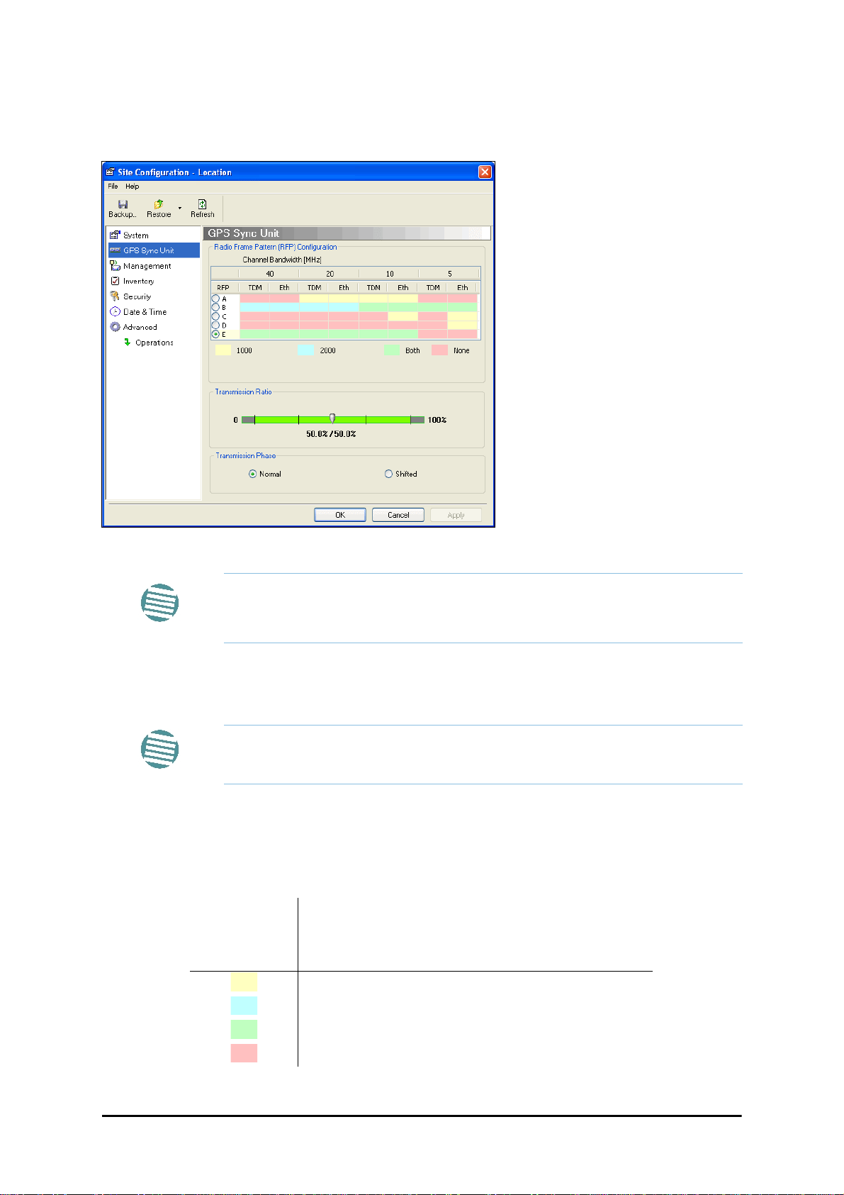
Site Configuration: GPS Sync Unit
This window is the main GSU configuration tool:
Figure 11-8: Site Configuration: GPS Sync Unit
The 1000 and 2000 labels refer to WinLink 1000 and RADWIN 2000 radios,
respectively. The actual annotation seen may vary, but the intention should
Note
be clear.
1. Setting the RFP for HSS
The GSU is automatically configured as HSS Master (HSM).
Ensure that no other collocated ODU is configured as HSM.
Note
If the hub site consists only of WinLink 1000 units, then any suitable RFP may be chosen.
If there are one or more RADWIN 2000 units, you must use RFP B or E.
The permitted RFPs are also dependent on channel bandwidth and are color coded as follows:
You May use RFP/
Channel
Bandwidth
combinations with
this color
For these collocated radios
WinLink 1000 only
RADWIN 2000 only
WinLink 1000 and RADWIN 2000 together
None - unavailable
RADWIN 2000 User Manual Release 2.5.40 11-8
Page 2
Configuring the GSU Chapter 11
There is a further restriction: If there are two distributed sites transmitting to each other,
they must both use the same RFP. This requirement, together with use of shifted transmission phase (item 3 below), ensures that communicating distributed sites to not interfere
with each other by transmitting simultaneously.
Two GSU managed sites transmitting with shifted transmission phase and using the same
RFP, transmit one half a RFD apart (see Figure 11-3 above).
2. Setting the Tx Transmission Ratio
Since the GSU is always HSM, it must be able to cater for hub site RADWIN 2000 C based
links. (See the RADWIN 2000 User Manual, Chapter 5). If you use asymmetric allocation,
shifted transmission phase becomes unavailable and you cannot “cascade” links as
described in step 1.
3. Choosing the Transmission Phase
Chose the Transmission Phase in accordance with considerations in step 1 above. If you
choose Shifted Phase then the Asymmetric Ratio selector is disabled.
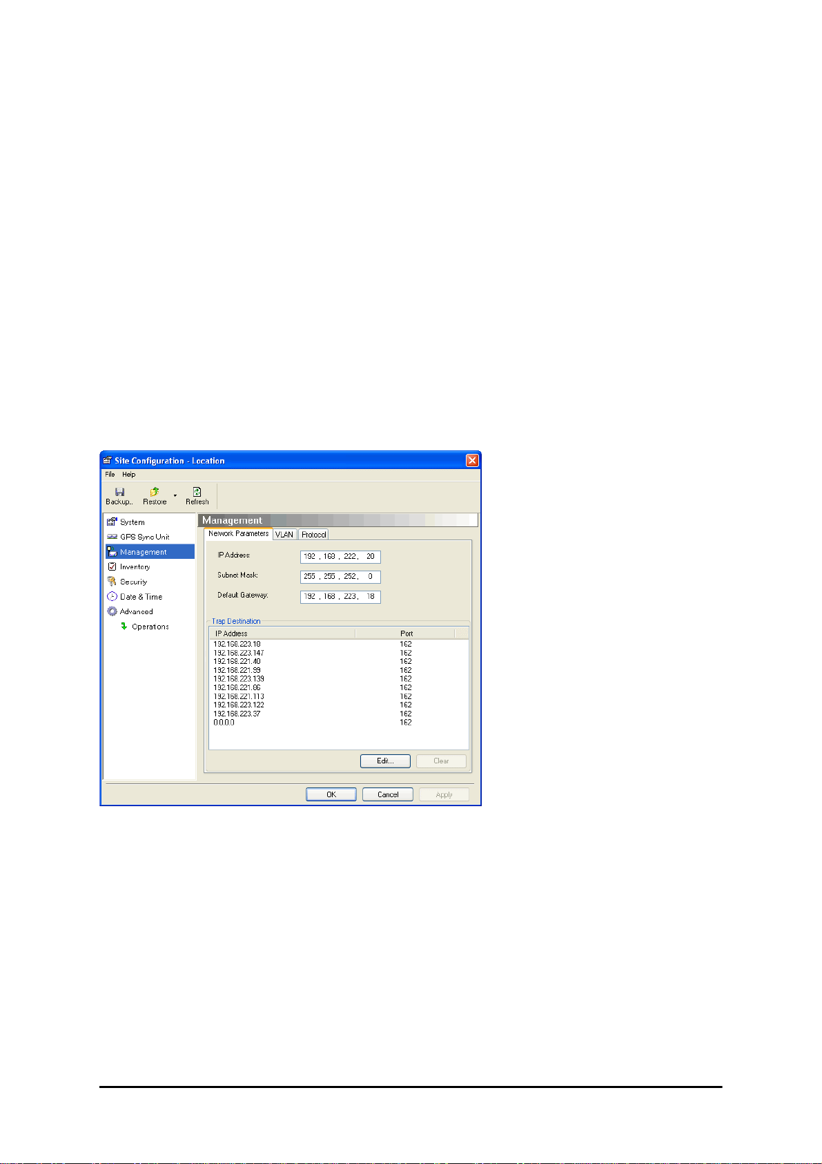
Site Configuration: Management
Figure 11-9: Site Configuration: Management
Here you set the GSU IP address, subnet mask and gateway. You also set trap addresses
here. It is identical to the corresponding panel for WinLink 1000.
RADWIN 2000 User Manual Release 2.5.40 11-9
Page 3
Configuring the GSU Chapter 11
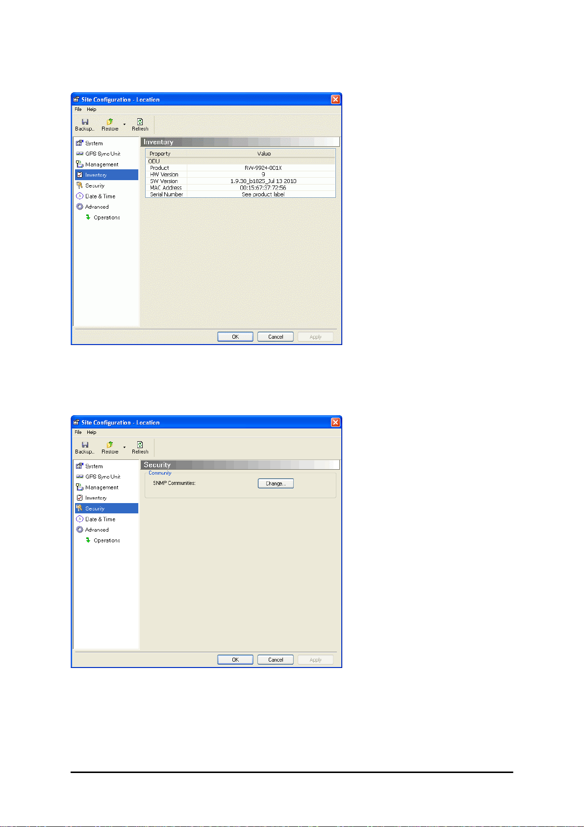
Site Configuration: Inventory
Figure 11-10: Site Configuration: Inventory
Site Configuration: Security
You can only change the SNMP Community stings:
Figure 11-11: Site Configuration: Security
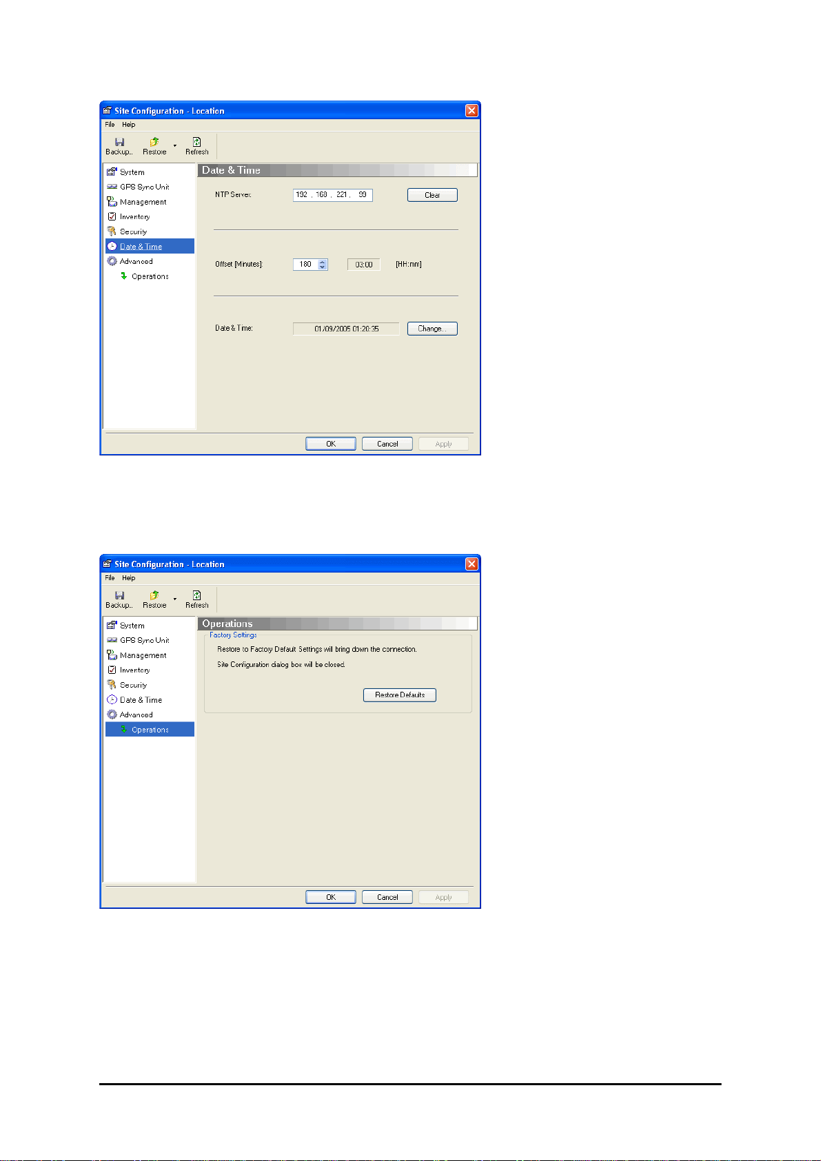
Site Configuration: Date and Time
ODU Recent events, alarms and traps are time-stamped from the time method chosen here
(NTP, managing computer, ODU default).
RADWIN 2000 User Manual Release 2.5.40 11-10
Page 4
Configuring the GSU Chapter 11
Figure 11-12: Setting the date and time for trap reporting
Site Configuration: Operations
The only available action here is Restore System Defaults:
Figure 11-13: Site Configuration: Operations
RADWIN 2000 User Manual Release 2.5.40 11-11
Page 5
GSU Preferences Chapter 11
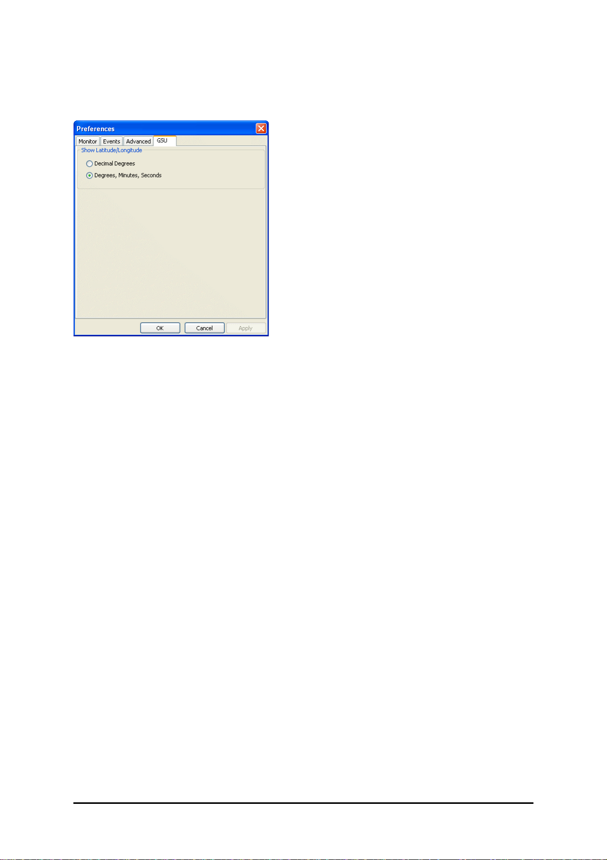
GSU Preferences
The Preferences window adds a new tab for the GSU:
Figure 11-14: Site Configuration: Operations
You may chose the units for latitude/longitude coordinates.
GSU Monitoring and Diagnostics
The monitoring and diagnostic reports are similar to those of WinLink 1000.
GSU Telnet Support
To configure the GSU with Telnet, start a Telnet session, using
telnet <GSU_ipaddr>.
For example, if you run Telnet as follows,
telnet 192.168.222.20
you will be asked for a user name and password. Y ou must log on with administr ator privilege
under user name,
The available commands are the same as for WinLink 1000 with the addition of four additional display commands and three additional set commands.
The additional display commands are
admin
and password
netman
.
display rfp
display ratio
display tx_phase
display gpsinfo
The last one display gpsinfo, is the most interesting:
admin@192.168.222.20-> display gpsinfo
Current GPS time 102941.000
RADWIN 2000 User Manual Release 2.5.40 11-12
Page 6

Software Update for GSUs Chapter 11
Current GPS latitude 51.500000
Current GPS N\S Indicator N
Current GPS longitude 0.000000
Current GPS E\W Indicator E
Current GPS number of satellites 09
Current GPS altitude 84.0
Command "display gpsinfo" finished OK.
The three additional set commands are
set rfp <index> (2-6)
set ratio <ratio>
set tx_phase <mode:1=normal,2=shifted>
Software Update for GSUs
All GSUs in a distributed site can be updated simultaneously. Use an IP list as described in
Chapter 15.
RADWIN 2000 User Manual Release 2.5.40 11-13
Page 7

RADWIN 2000
Broadband Wireless Transmission System
USER MANUAL
RELEASE 2.5.40
Part 3: Advanced Installation
UM 2000-2540/02.11
Page 8

Chapter 12
Monitored Hot Standby
Installation Procedure
What is a RADWIN Monitored Hot Standby
The RADWIN Monitored Hot Standby (MHS a.k.a 1+1) is a duplicated link set up as a primary
link and a secondary link in hot standby mode as shown in Figure 12-1 below.
Figure 12-1: RADWIN Monitored Hot Standby
RADWIN 2000 User Manual Release 2.5.40 12-1
Page 9

What RADWIN MHS provides Chapter 12
RADWIN MHS provides redundancy and backup to TDM services. It is designed to provide
high reliability high-capacity Point-to-Point links. The RADWIN MHS is -
• Designed to provide redundancy and high reliability for carrier class operators
• Optimized for high capacity links operating in license-free bands
• A comprehensive solution providing protection against both equipment failure and loss
of air interface, by simple connectivity between a primary link and a secondary link
The main service redundancy features of the RADWIN MHS are –
• TDM service cut-over from the primary to the secondary link is completely automatic
• TDM service cut-over time no more than 50 ms
• Automatic restore to primary link as soon as it becomes available
• Support for up to sixteen TDM channels for RADWIN 2000 and four TDM channels for
WinLink 1000.
MHS is supported between -
• two WinLink 1000 links
• two RADWIN 2000 links
• a WinLink 1000 link and a RADWIN 2000 link.
What RADWIN MHS provides
Equipment Protection
Equipment protection is provided for the electrically-active network elements, ODU and IDU.
The primary IDU and the secondary IDU are connected by a cable to monitor failure and to
control protection switching. Switching time is less than 50ms.
When connecting two WinLink 1000 links as 1+1, one dual-polarization antenna can be
shared by the primary link and the secondary link.
Air-Interface Protection
Air-Interface protection is unique to RADWIN and is optimized for wireless links operating in
license-free bands.
The primary link and the secondary link use different frequency channels. If the air-interface
of the primary link is disturbed and cannot carry the required TDM service, then the system
automatically switches to the secondary link.
In addition, improved robustness and frequency planning flexibility is achieved, as the primary and secondary air interfaces can operate in the same frequency band or in different frequency bands.
Automatic Channel Selection (ACS) can be configured for each link to add additional robustness.
The primary and secondary links are synchronized using Hub Site Synchronization (HSS).
It is recommended that both sites be installed with HSS cables. If HSS fails at one site, it can
be operated from the other site by remote configuration.
RADWIN 2000 User Manual Release 2.5.40 12-2
Page 10
Purpose of this Chapter Chapter 12
Purpose of this Chapter
This chapter is an installation and maintenance guide for RADWIN MHS. It applies to all RADWIN radio products able to support the Monitored Hot Standby operational mode.
Who Should Read this
This chapter is intended for persons responsible for the installation and maintenance of RADWIN MHS. To use it you need to know how to -
• Install a WinLink 1000 radio link
• Install a RADWIN 2000 radio link
• Use the RADWIN Manager software
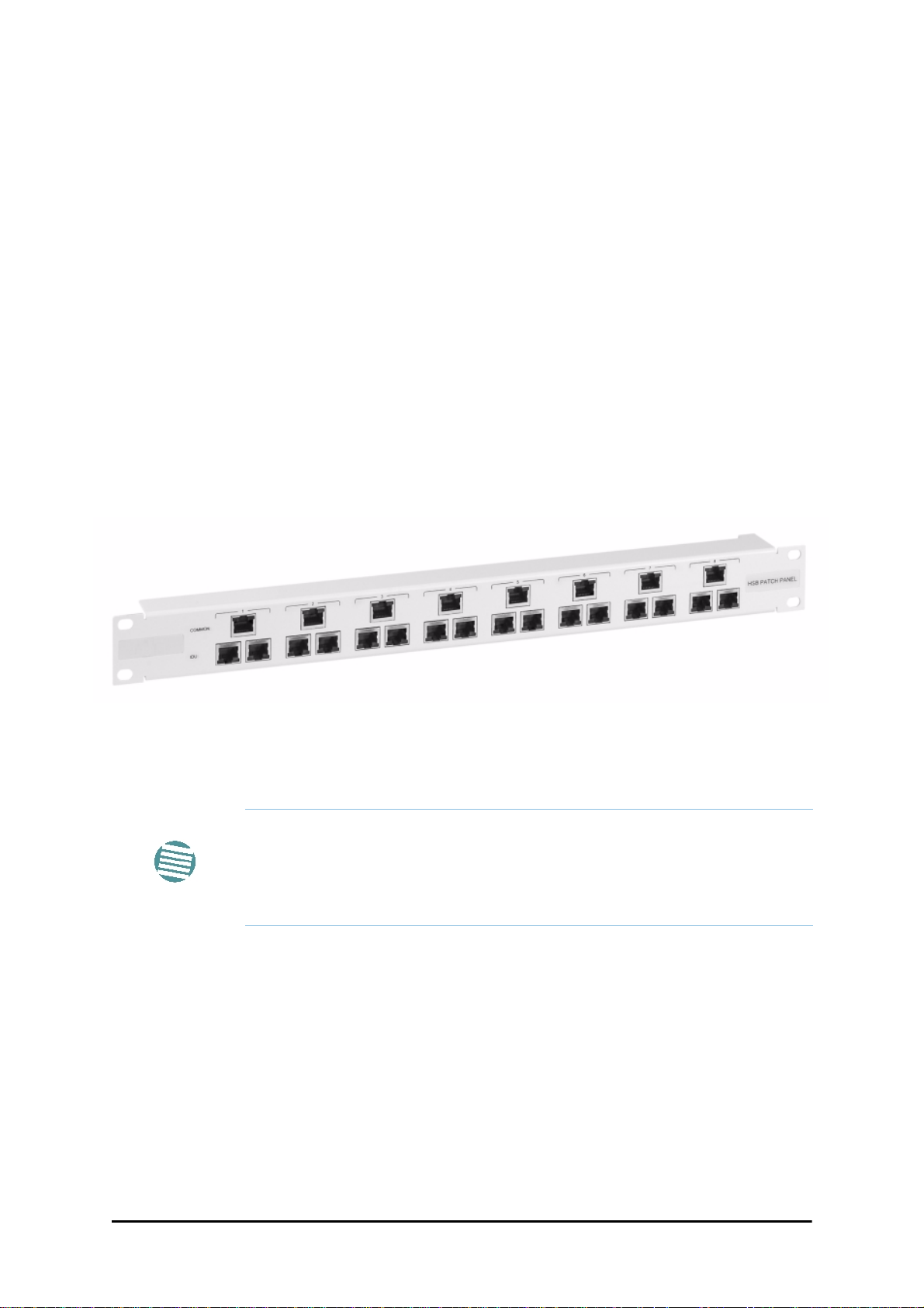
RADWIN MHS Kit Contents
• One Y-Connection Patch Panel
• One MHS cable
Figure 12-2: RADWIN Y-Connection Patch Panel
Installing a RADWIN MHS
The following procedure is substantially generic to all RADWIN radio
products. Differences between WinLink 1000 and RADWIN 2000 class
products will be stated explicitly. What you see on your running RADWIN
Note
Figure 12-1 above is a schematic of a RADWIN MHS. Figure 12-3 shows how to connect
the IDUs to the Patch Panel.
Manager may differ in some details from the screen captures used to
illustrate this chapter.
RADWIN 2000 User Manual Release 2.5.40 12-3
Page 11

Installing a RADWIN MHS Chapter 12
Figure 12-3: How to connect the IDUs to the Patch Panel
•With RADWIN 2000 links yo u can protect up to 16 TDM ports. To pro-
tect more than eight TDM ports use two Patch Panels at each site.
• Ethernet services are carried independently by primary and second-
Note
ary links. Each link carries different Ethernet traffic. MHS does not
protect Ethernet traffic.
In what follows, it will be assumed that –
1. We will depart from our usual Site A / Site B conventions. Sites A and B on the primary link
will be Sites 1.2 and 1.4 respectively. The corresponding sites on the secondary link will be
Sites 2.2 and 2.4. The site names reflect their IP addresses. This is a useful convention and
is reflected in the screen captures below.
2. The link will be managed from Site 1.2; Site 1.4 may be a remote site.
3. The links intended as the primary and secondary will be referred to their respective names,
Primary Link and Secondary Link as shown in Figure 12-1 above, despite their having yet
to be installed.
To install a Hot Standby Link:
1. Set up Primary Link in the usual way. Ensure that it is fully operational in accordance
with the relevant instructions in Part 1 of the User Manual.
Do not proceed unless this condition is fully met!
Note
2. Connect user equipment to Site 1.4.
3. At Site 1.2, disconnect the TDM cables from the external equipment or disconnect
external equipment from the Hot Standby Patch Panel.
4. The HSS cable (connecting the ODUs) should be connected at Site 1.2. The ODU
belonging to the primary link should be configured as HSM, whereas the ODU
belonging to the secondary link should be configured as HSC-CT.
5. Establish Secondary Link in the usual way, with HSS enabled. The two link fre-
quencies should be at least 5MHz apart.
RADWIN 2000 User Manual Release 2.5.40 12-4
Page 12
Installing a RADWIN MHS Chapter 12
6. Connect the MHS cables at Sites A and B as shown in Figure 12-1 and Figure 12-
3 above.
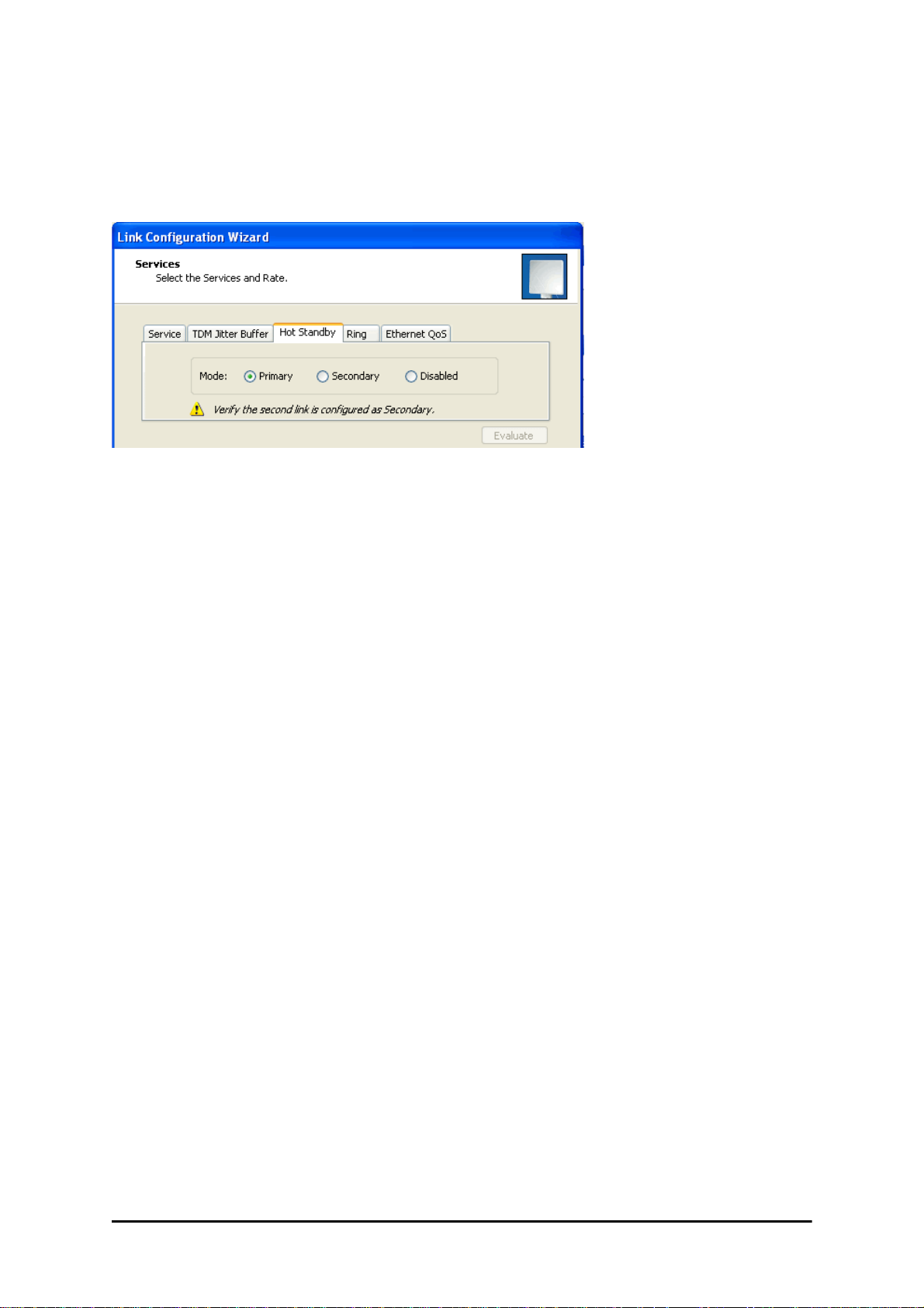
7. Run the Configuration Wizard for Primary Link. Activate TDM services in the usual
way. Navigate to the Hot Standby tab, in the Services Configuration panel:
Figure 12-4: Services Configuration Panel: Hot Standby mode selection
Check the Primary button to configure Primary Link as the primary link.
8. Complete the Wizard, and then move to Secondary Link.
9. Repeat step 7 for Secondary Link. For the Services Hot Standby tab, this time, check
the Secondary button.
10. Complete the Wizard.
11. At Site 1.2, reconnect the Hot Standby Patch panel to the external equipment.
From this point on, we will simply refer to primary and secondary link (no capitalized names).
At the end of the process, the RADWIN Manager main windows should look like this:
RADWIN 2000 User Manual Release 2.5.40 12-5
Page 13
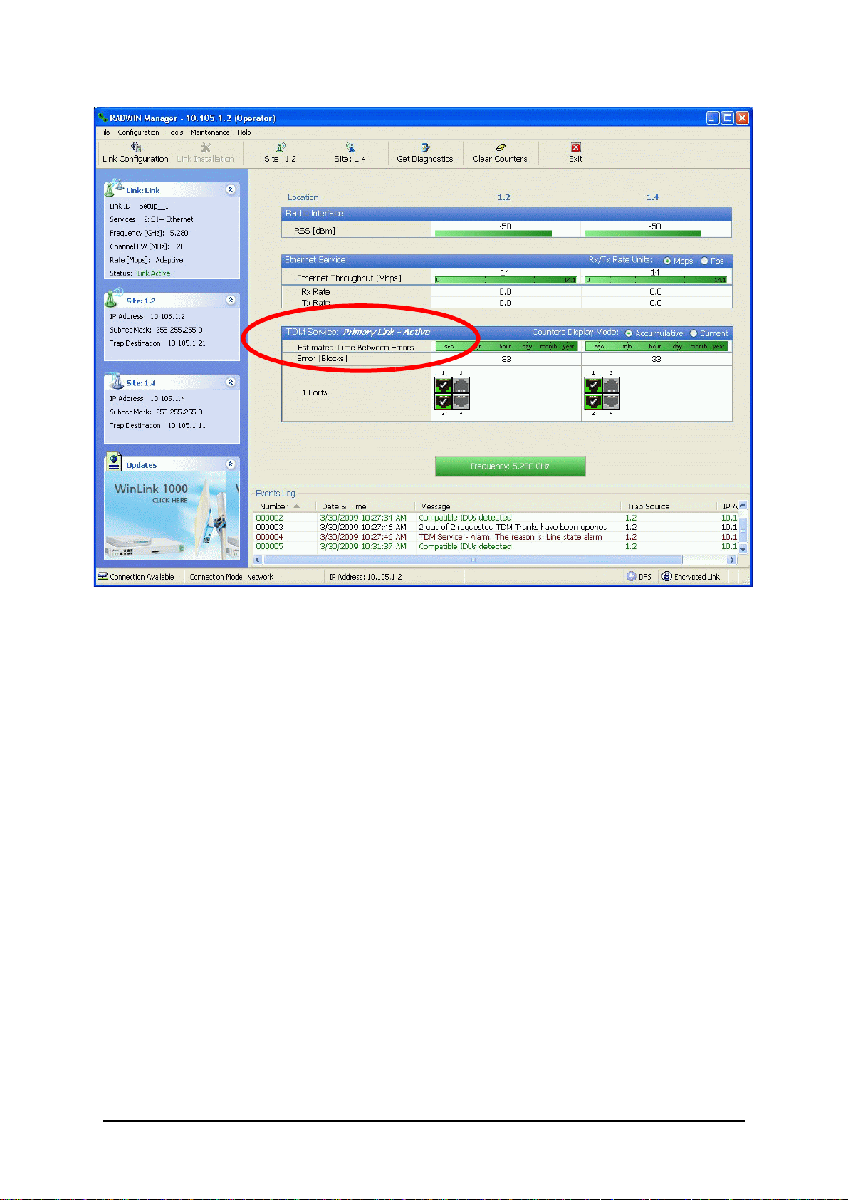
Installing a RADWIN MHS Chapter 12
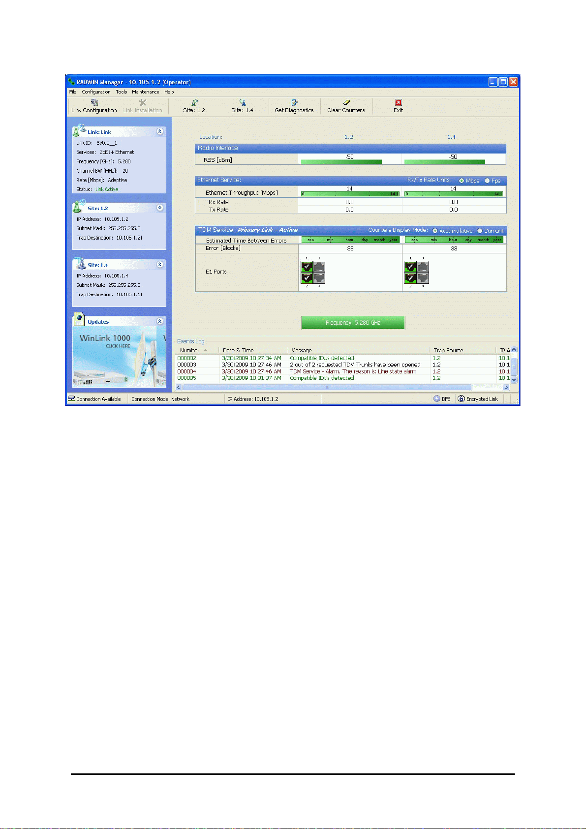
Figure 12-5: The primary link under normal operation
RADWIN 2000 User Manual Release 2.5.40 12-6
Page 14
Installing a RADWIN MHS Chapter 12
Figure 12-6: The secondary link under normal operation
To see what happens following a cut-over from the primary link to the secondary link, you
need to have running two copies of the RADWIN Manager – one logged into the primary link,
and one logged into the secondary link.
Here then, is the situation after a cut-over to the secondary link:
For the primary link, the following window will appear for a few seconds:
RADWIN 2000 User Manual Release 2.5.40 12-7
Page 15
Installing a RADWIN MHS Chapter 12
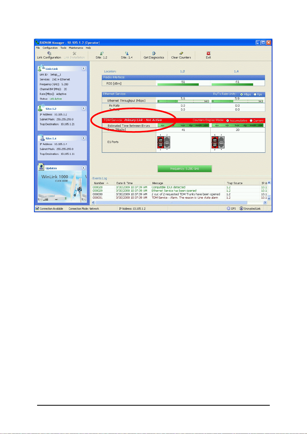
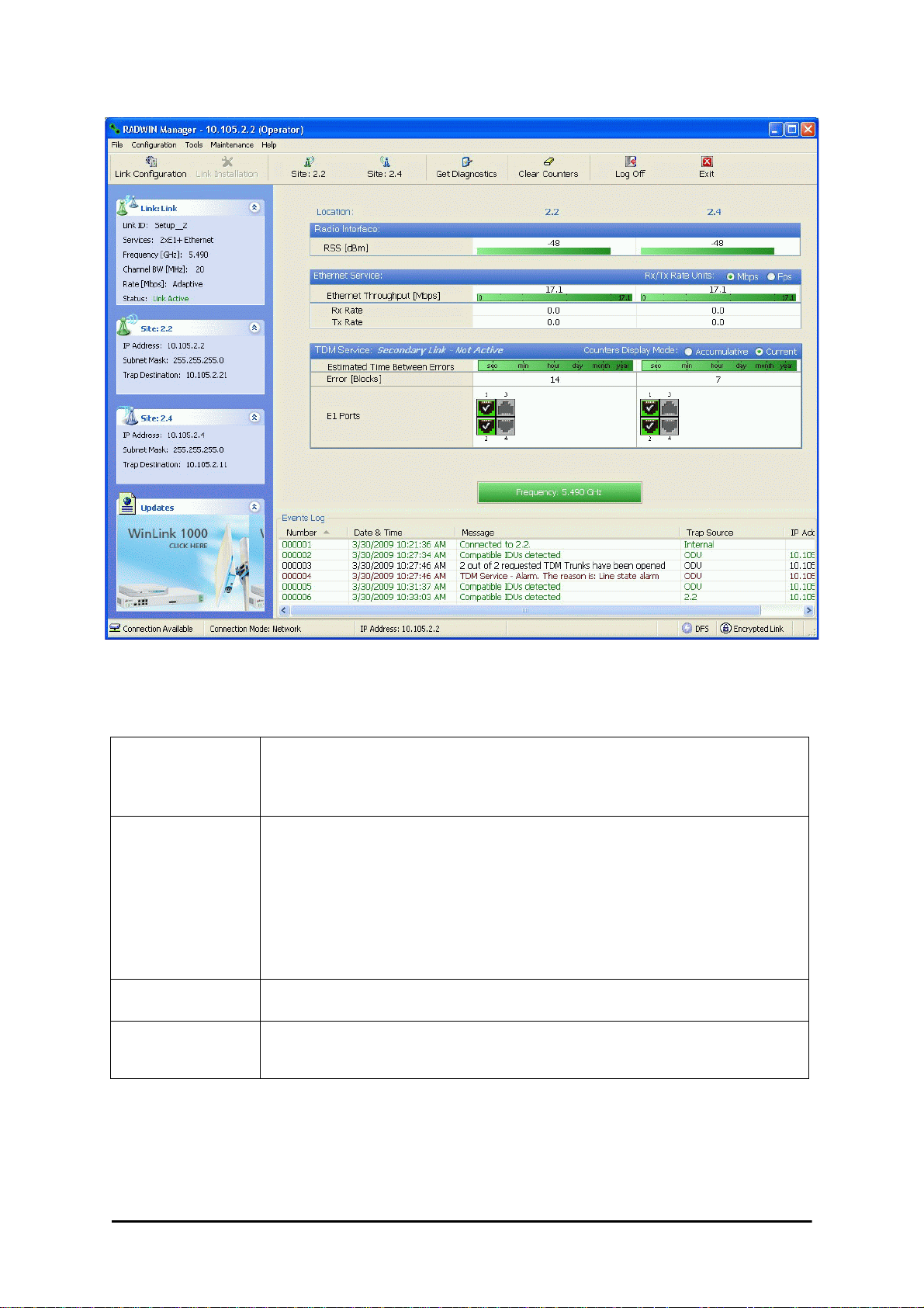
Figure 12-7: Primary link a few seconds before regular No-Link display
It will then revert to the standard No-Link-available window.
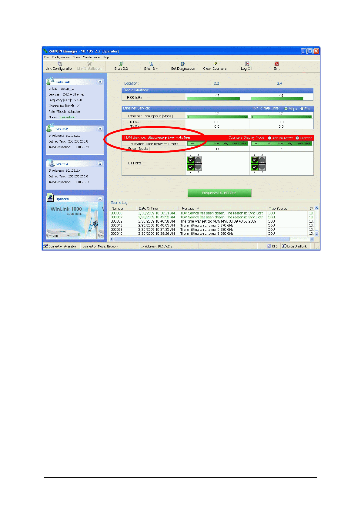
On the secondary link Manager window, you will see a window like this:
RADWIN 2000 User Manual Release 2.5.40 12-8
Page 16
Maintaining a RADWIN MHS Link Chapter 12
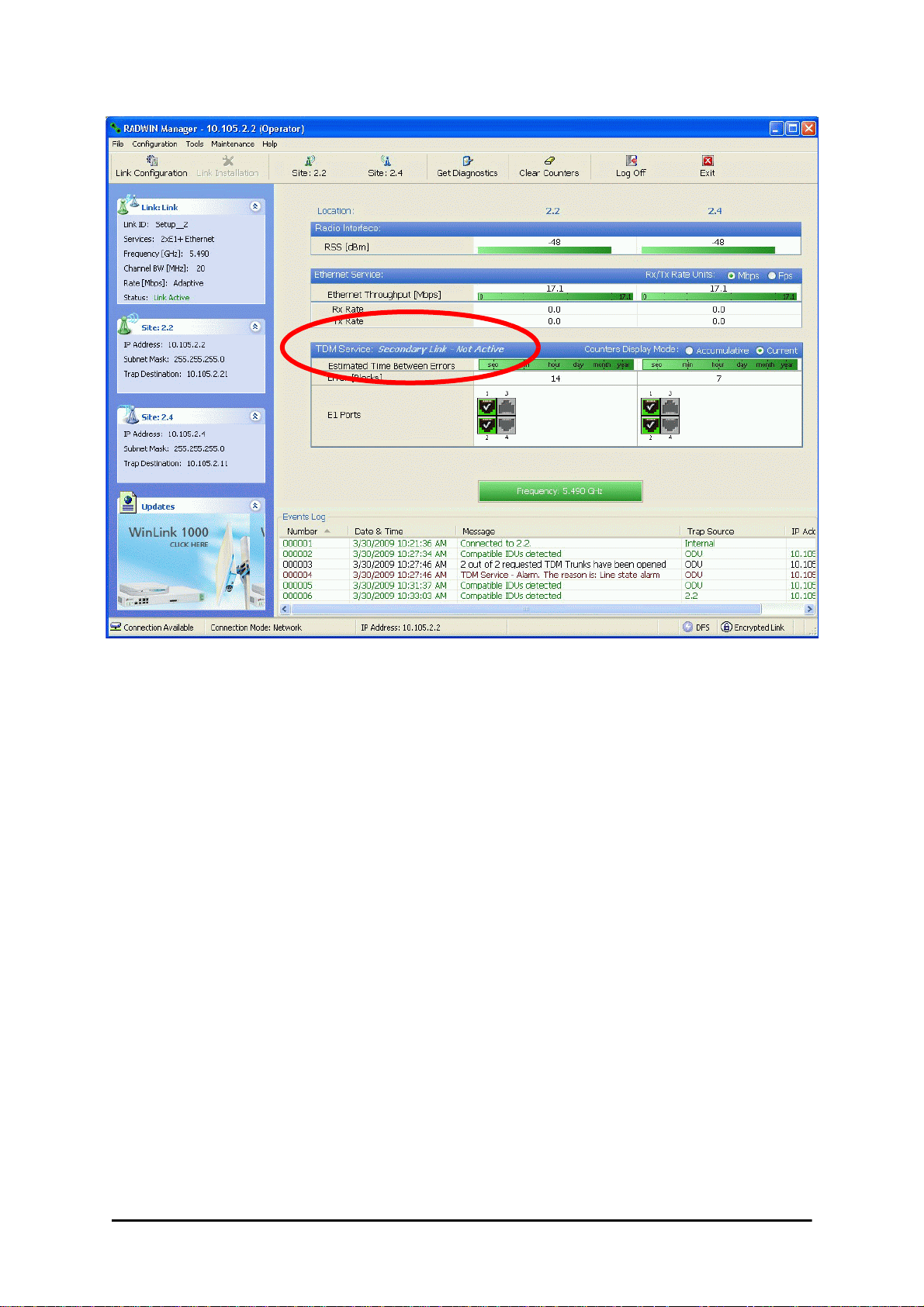
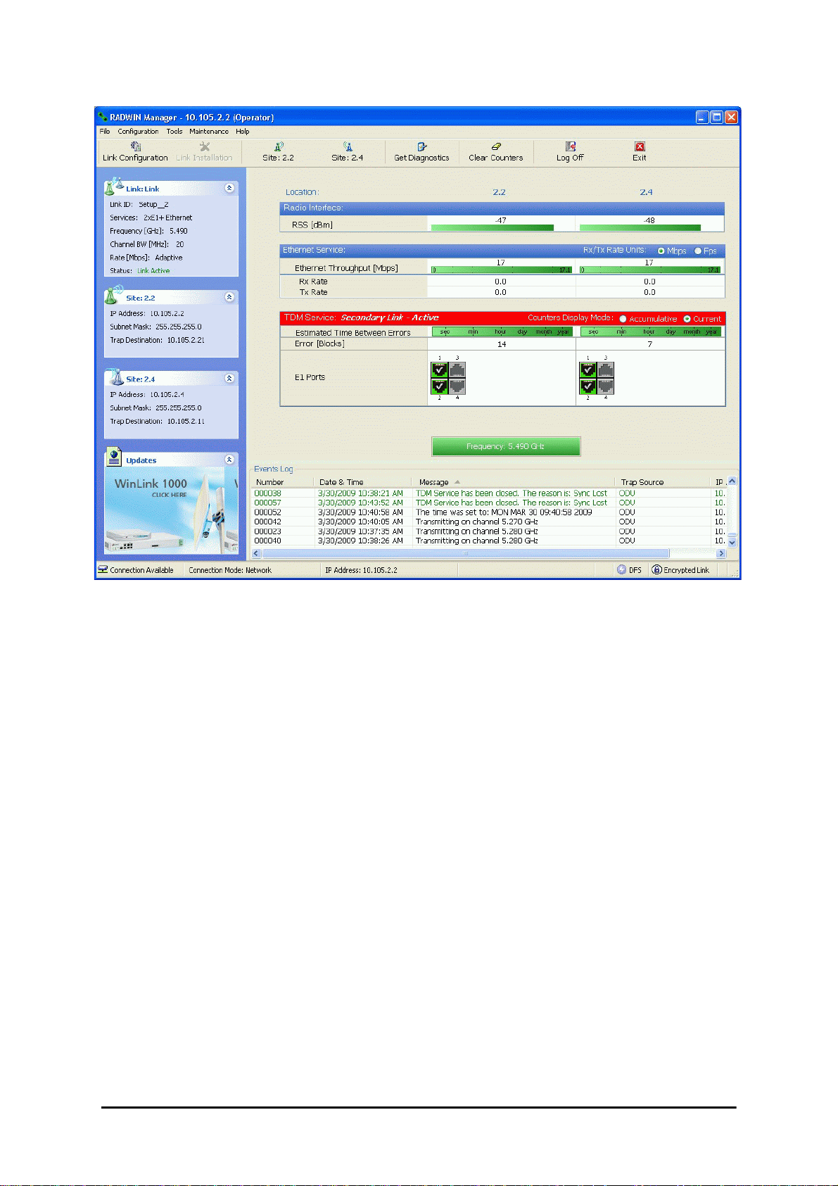
Figure 12-8: Secondary Link operating as the Hot Standby link
Notice that the active link notice is highlighted in red, so that there is no mistaking which link
is operational.
Maintaining a RADWIN MHS Link
IDU Replacement
There are two situations, which must be treated differently.
Situation 1:
To replace either of the IDUs at Site 1.4 or the IDU at Site 2.2, nothing special is required.
Simply disconnect the IDU to be replaced – and replace it with a new one. Replacing a secondary link IDU obviously has no effect on the TDM service. Disconnecting the Site 1.4 primary IDU activates Hot Standby. After the Site 1.4 primary IDU is replaced, the Link will
detect the change and switch back to the primary link.
If you replaced the Site 2.2 IDU, remember to reconnect the MHS cable.
Situation 2:
Replacing the Site 1.2 IDU is different, and requires several steps.
To replace the Site 1.2 primary link IDU:
1. Power off the Site 1.2 IDU. This activates the secondary link using Hot Standby.
RADWIN 2000 User Manual Release 2.5.40 12-9
Page 17

ODU Replacement Chapter 12
2. Run the Configuration manager on the secondary link, and in the Hot Standby panel
of Figure 12-4 above, check the Disabled button.
3. Replace the Site 1.2 IDU without connecting it to the ODU (to prevent transmission
by the primary link with the undefined IDU).
4. Reconnect the MHS cable between the IDUs at Site 1.2.
5. Again, run the Configuration Wizard on the secondary link, and in the panel of
Figure 12-4 above, check the Secondary button to re-enable the link as secondary.
6. Connect the new Site 1.2 IDU to its ODU.
The Hot Standby will automatically revert to the primary link within 50ms.
ODU Replacement
Both the primary and secondary replacement ODUs require pre-configuration prior to insertion into the link. The items to be pre-configured are
•HSS mode
•Link ID
•Frequency
• Hot Standby mode – using the new Services panel in Figure 12-4 above
• IP address (optional)
Pre-configuration must be carried out before the new ODU is
connected to its IDU. If you try to do it “live” against its IDU, it will
Note
cause spurious transmissions and a service break.
To pre-configure an ODU:
1. Attach the new ODU to an IDU or a PoE device.
2. Run the RADWIN Manager and use Hot Standby tab of Figure 12-4 above to configure the new ODU to Primary or Secondary mode as required.
3. Ensure that it is set to the proper HSS mode in accordance with Figure 12-4 above.
Enter the required Link ID and frequency.
To replace an ODU for primary or secondary link, at either site:
• Install the pre-configured ODU. (Since the other link is working normally, nothing
need be done with it. If the secondary ODU was replaced, TDM service remains as is
on the primary link. If the primary ODU was replaced, then the TDM service will shift
back to the primary link.)
Switching Logic
Switching from Primary Link to Secondary Link
Switching from primary link to secondary link will occur following:
• Loss of the primary air interface due to sync loss
RADWIN 2000 User Manual Release 2.5.40 12-10
Page 18
Switching from Primary Link to Secondary Link Chapter 12
• Loss of the primary air interface due to failure of the receiver to acquire expected E1/
T1 data during a period of 24ms
• The Primary equipment (either ODU or IDU, local or remote) is powered off
Following the switch from the primary to the secondary link, the primary and secondary link
Manager main windows should look like this:
Figure 12-9: Primary link after the switch over to secondary link (After a few seconds the display moves to No-Link display, with TDM ports grayed out. )
RADWIN 2000 User Manual Release 2.5.40 12-11
Page 19
Switching back from the Secondary to the Primary Link Chapter 12
Figure 12-10: Secondary link operating after the switch over to secondary. (After a few
moments the TDM icons become green. )
Switching back from the Secondary to the Primary Link
Switching back from the secondary link to the primary link will occur after the primary link has
become and remains fully functional for a continuous period of at least one second. F ollowing
reversion from the secondary link to the primary link, the Manager main windows should look
like this:
RADWIN 2000 User Manual Release 2.5.40 12-12
Page 20
Switching back from the Secondary to the Primary Link Chapter 12
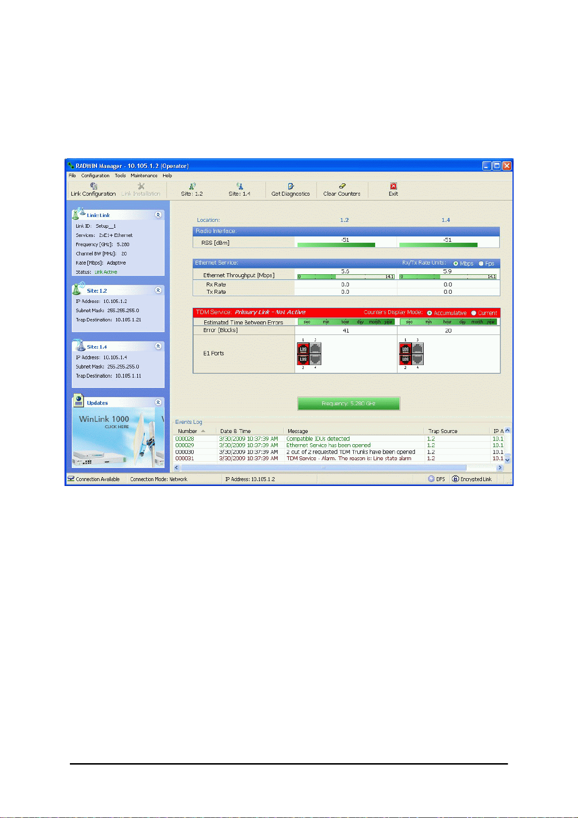
Figure 12-11: Primary link operating after the switch back from secondary
RADWIN 2000 User Manual Release 2.5.40 12-13
Page 21
System Operation description Chapter 12
Figure 12-12: Secondary Link operating after the switch back to Primary
System Operation description
• TDM services are carried by the primary link
Normal operation
Switching to backup
Backup operation • TDM services are carried by the secondary link
Switching back to
primary
• The secondary link (equipment and air interface) is operating but not carrying user traffic
•TDM ports on the secondary IDUs are tri-state
• Switching to secondary will occur in the following cases:
• Loss of the primary air interface due to sync loss
• Loss of the primary air interface due to failure of the receiver to acquire expected
TDM data during a period of 24ms
• Primary equipment power off (either ODU or IDU, local or remote)
• The switching result would be:
• TDM ports on the primary IDUs turn to tri-state
• TDM ports on the secondary IDUs become active
• Switching back to primary will occur as soon as the Primary link is fully functional for 1
second
RADWIN 2000 User Manual Release 2.5.40 12-14
Page 22

Chapter 13
The RADWIN Ethernet
Ring
Scope
The description of RADWIN Ethernet Ring in this Chapter is completely generic: Both WinLink
1000 and RADWIN 2000 links may participate in an Ethernet ring.
VLAN IDs are used by RADWIN products in three separate contexts:
Management VLAN, Traffic VLAN and Ethernet Ring. It is recommended that
Caution
What is an Ethernet Ring
you use different VLAN IDs for each context.
An Ethernet ring consists of several nodes connected by hops (links). Loops are not allowed
with Ethernet; therefore one hop is a Ring Protection Link (RPL) which “blocks” Ethernet
traffic. In the event of failure in the ring, the Ring Protection Link unblocks and Ethernet traffic in the ring is restored.
Some terminology:
• Normal State – all member links are functional except the RPL which is blocked.
• Blocked - the air-link is up but Ethernet traffic is not transmitted across the link. The
Ethernet service panel for the RPL in the RADWIN Manager is labeled Idle
• Unblocked - Ethernet traffic is transmit ted across the RPL. The Ethernet service
panel for the RPL in the RADWIN Manager is labeled Active
• Protection State – a member link is broken and the RPL passes Ethernet traffic
• Ring Protection Link - as described above
• Ring Link - any member link controlled by the RPL
• Independent Link - not subject to ring protection
RADWIN 2000 User Manual Release 2.5.40 13-1
Page 23

RADWIN Ethernet Ring Chapter 13
• Ring Protection Message (RPM) - control message used to monitor and control the
ring.
RPM messages are broadcast, so it is essential (to prevent flooding) to
associate the RPL and member Ring LInks with a VLAN ID. This requires in
Note
turn, that equipment used in the ring either supports VLAN or can
transparently pass through VLAN tagged packets.
RADWIN Ethernet Ring
The following figure describes the RPL behavior during a ring failure and recovery cycle.
Figure 13-1: Ring Protection mechanism
RADWIN 2000 User Manual Release 2.5.40 13-2
Page 24

RADWIN Ethernet Ring Chapter 13
The steps below follow the numbering in Figure 13-1:
1. Normal operation
Ethernet traffic runs in the ring, but does not pass through the RPL, which is blocked. The
RPL does however, broadcast RPM packets through the ring.
2. Ring Link down, RPL notified
The RPL detects a link-down condition by the non-arrival of an RPM packet. It remains
blocked for the Minimum time for failure detection which is configurable using the
RADWIN Manager (see page 13-9).
3. Ring Link down, RPL unblocked for traffic
The RPL unblocks for Ethernet traffic after the Minimum time for failure detection
expires and no RPM message has been received.
4. Ring Link restored but still blocked for traffic
The Ring Link is restored, but remains blocked for the Minimum time for recovery, set
using the RADWIN Manager, to avoid rapid fluctuations leading to potential short term
loops (see page 13-9).
5. Ring Link restored, RPL blocked for traffic
The RPL blocks to Ethernet traffic after the Minimum time for recovery expires and
restores Ethernet traffic to the Ring Link (with a special RPM packet).
Return to 1.) Ring Link restored, RPL blocked for traffic
The ring is back to normal operation.
With RADWIN links, RADWIN’s Ring Protection solution prevents Ethernet loops in the ring at
all times. The ring is always broken somewhere.
• Under a ring configuration a RADWIN Ring Link that was down and commences recovery, keeps blocking Ethernet traffic. The RPL identifies this situation, blocks itself and
then unblocks the other Ring Link. This is the transition from step 4 to 5 in
Figure 13-1.
• If the failed hop is not a RADWIN
• If the hop Ring Link can signal that it is down by issuing a Loss of Signal (LOS) at
the Ethernet port, then the RPL will control the RADWIN link connected to that
port in the same manner as described above, to prevent an Ethernet loop.
• Otherwise, there may be a short loop period when the RPL is still open for traffic
and the Ring Link is also unblocked during the Minimum time for recovery.
link then there are two possibilities:
RADWIN 2000 User Manual Release 2.5.40 13-3
Page 25
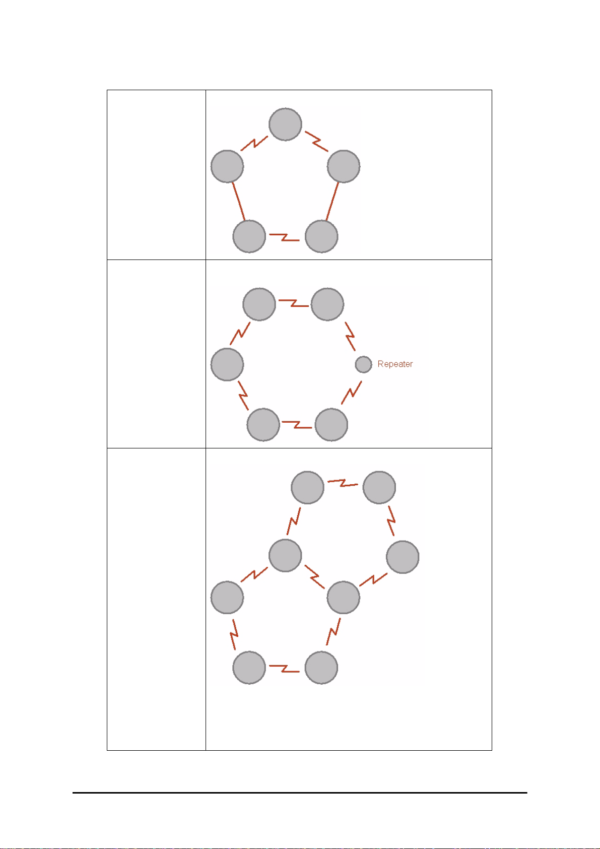
Ethernet Ring Topologies Supported by RADWIN Chapter 13
Ethernet Ring Topologies Supported by RADWIN
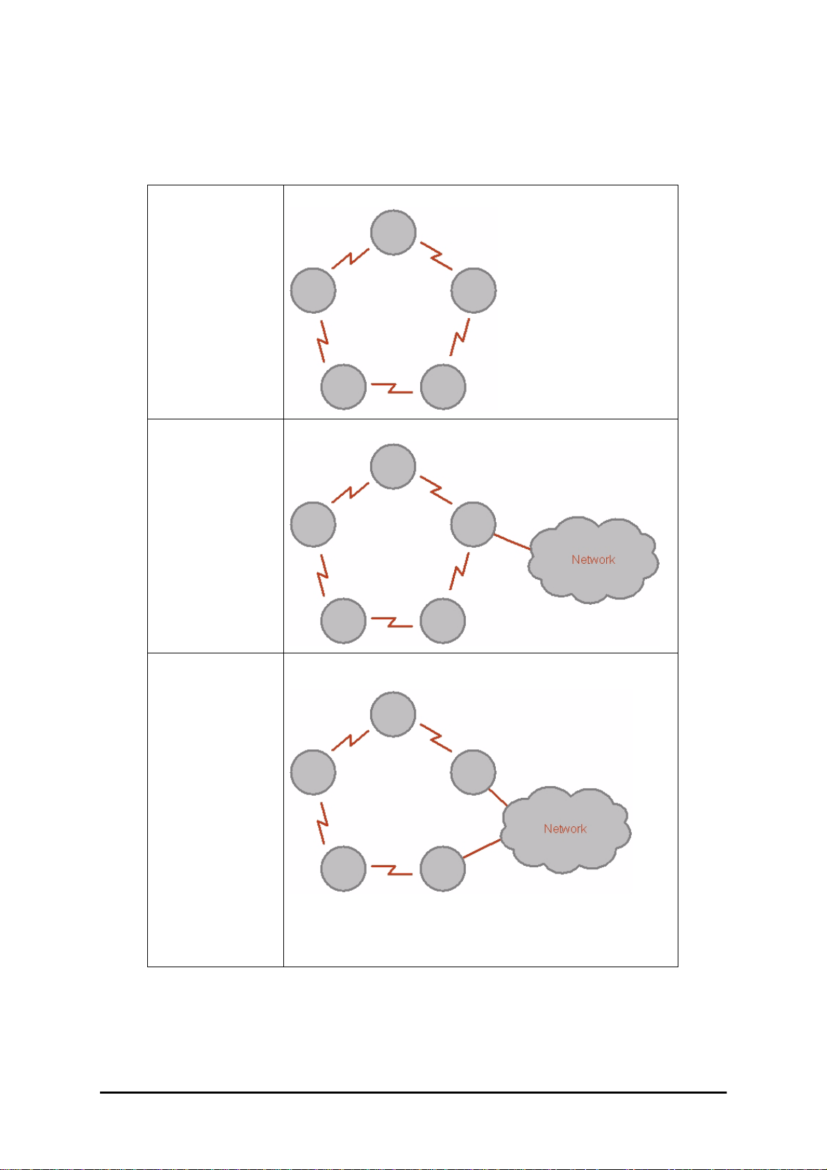
The following ring topologies are supported:
Table 13-1: Topologies supported by RADWIN Ethernet Ring
The ring is not connected to other rings
Stand-alone ring
One of the nodes is connected to another network / ring:
Single-homed ring
Dual-homed ring
Two adjacent nodes are connected through a non-RADWIN link (e.g. micro
wave or fiber):
Note:
• The network has to be layer 2 and support VLANs
• The ring control broadcasts RPM packe ts. Hence it i s recommend ed to
prevent these packets from propagating into the network
RADWIN 2000 User Manual Release 2.5.40 13-4
Page 26
Ethernet Ring Topologies Supported by RADWIN Chapter 13
Table 13-1: Topologies supported by RADWIN Ethernet Ring (Continued)
Some of the hops are connected through non-RADWIN links:
Mixed ring
Some of the hops are connected through RADWIN links with PoE devices, not
supporting ring functionality:
Repeater sites
Shared ring
RADWIN rings with shared hops.
Note:
• A RADWIN link hop can be a part of up to 4 rings
• The RPL cannot be a shared link
• The two RPLs should use different Minimum Time for Acti vation v alues
to prevent duplicate action causing a loop
RADWIN 2000 User Manual Release 2.5.40 13-5
Page 27

Protection Switching Chapter 13
Protection Switching
Protection switching occurs upon failure in the ring.
The Ethernet service restoration time depends on the number of hops in the ring. With four
hops the Ethernet service is restored in less than 50 ms.
In single and dual homed topologies the service restoration may take longer due to the aging
time of the external switches. Switches that are immediately aware of routing changes reduce
the restoration time.
Hardware Considerations
Ethernet Ring Protection is supported by the IDU-C, IDU-E and PoE.
A typical Ring Protection Link consists of an IDU-C or new style IDU-E, a PoE and two ODUs
as shown in Figure 13-2. Hence one end of the RPL and of ring controlled links, as shown in
Figure 13-2 has to be an IDU. It is recommended to have an IDU at each node to have the
flexibility to change the RPL.
A ring node is built from two ODUs from adjacent links. The ODUs can be connected to either
an IDU or to a PoE device as in Figure 13-2. Port names in the IDU are shown.
Figure 13-2: Node with IDU and PoE device
Connect the switch at the site only to one IDU.
Note
The switching function is carried out by the IDU-Cs and IDU-Es, both of which provide Layer
2 support (see Chapter 14).
Special Case: 1 + 1 Ethernet Redundancy
The same device may be used to provide economic 1 +1 redundancy for a single link.
A 1+1 Ethernet is a ring with two nodes. One of the links is RPL.
RADWIN 2000 User Manual Release 2.5.40 13-6
Page 28

Using RADWIN Manager to Set up a Ring Chapter 13
The equipment in a 1+1 Ethernet installation is as follows:
Figure 13-3: 1+1 Ethernet
Figure 13-4: Using IDU-C or IDU-E with PoEs for the RPL
Notice that link content drops from four PoEs plus two switches to two PoEs and two IDU-Cs
or IDU-Es.
Using RADWIN Manager to Set up a Ring
Creating a Ring using RADWIN Manager requires two stages:
6. Set up each participating link separately, in the usual way
7. For each link, run the Configuration wizard to define it as RPL or a Ring Link
• The Ring uses a VLAN ID for the RPL. It is used to manage the Ring
and nothing else; it is completely separate from the management
and traffic VLANs referred to elsewhere
Note
Here then, is step 2 in more detail:
• A regular Ring Link may be a member of up to four rings and each of
their RPL VLAN IDs must be configured
RADWIN 2000 User Manual Release 2.5.40 13-7
Page 29
Using RADWIN Manager to Set up a Ring Chapter 13
To integrate a link into an Ethernet Ring:
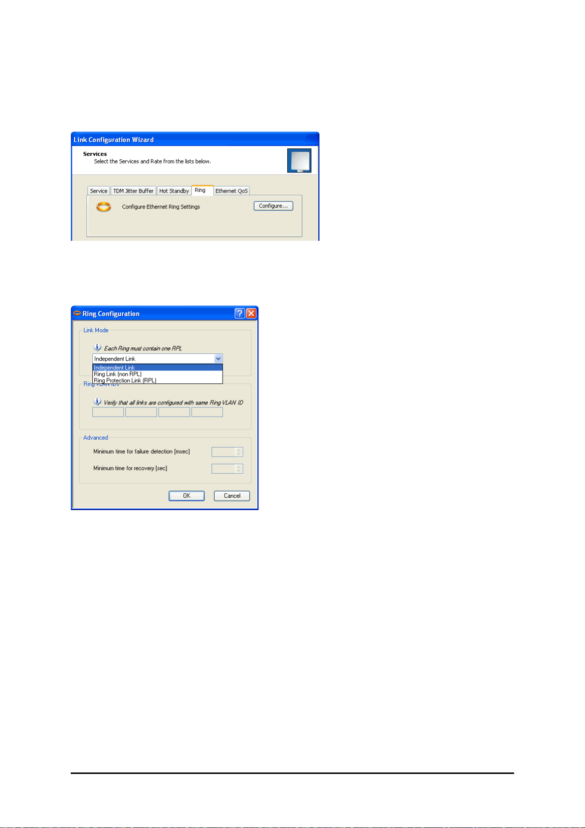
1. Using either the Installation or Configuration wizards, navigate to the Services window and chose the Ring tab.
Figure 13-5: Services window with Ring selected
2. Click Configure. The Ring definition window is displayed. The default is Independent Link and is used when the link is not part of any Ring.
Figure 13-6: Ring Options
3. To configure the link as a regular Rink link, click Rink Link (Non- RPL) and enter
the ring LAN VIDs (at least one) to which it belongs and click OK:
RADWIN 2000 User Manual Release 2.5.40 13-8
Page 30
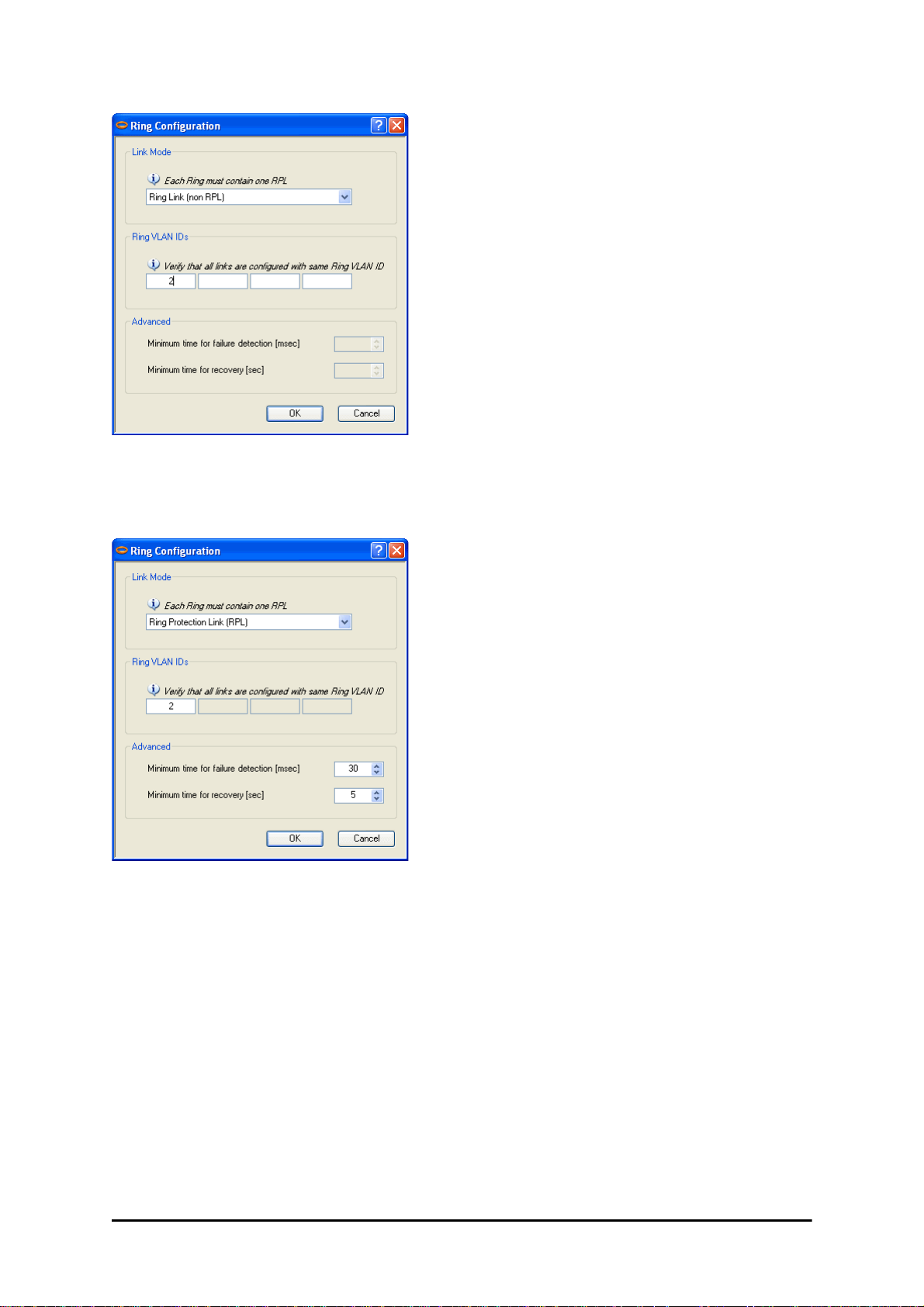
Using RADWIN Manager to Set up a Ring Chapter 13
Figure 13-7: Configuring Ring LAN VIDs
4. To configure the link as RPL, click Ring Protection Link (RPL) and enter its Ring
VID.
Figure 13-8: Configuring RPL VIDs
5. Enter the minimum times for failure detection and recove ry.
For dual-homed configurations, where part of the ring goes through the core, if a
core segment fails, the core should be allowed to recover before the RPL enters Protection State. Otherwise, it could happen that both the core and the RADWIN ring
will switch in parallel. You should therefore, configure a Mi nimum time for failure
detection high enough to take this possibility into account.
The Minimum time for recovery is a delay switch to prevent r a pid “on-o ff” fluctuations. It functions like a delay switch use to protect electrical devices from rapid
“on-off” power fluctuations, which in this context, may lead to potential short term
loops.
6. Click OK to accept your settings.
RADWIN 2000 User Manual Release 2.5.40 13-9
Page 31
Using RADWIN Manager to Set up a Ring Chapter 13
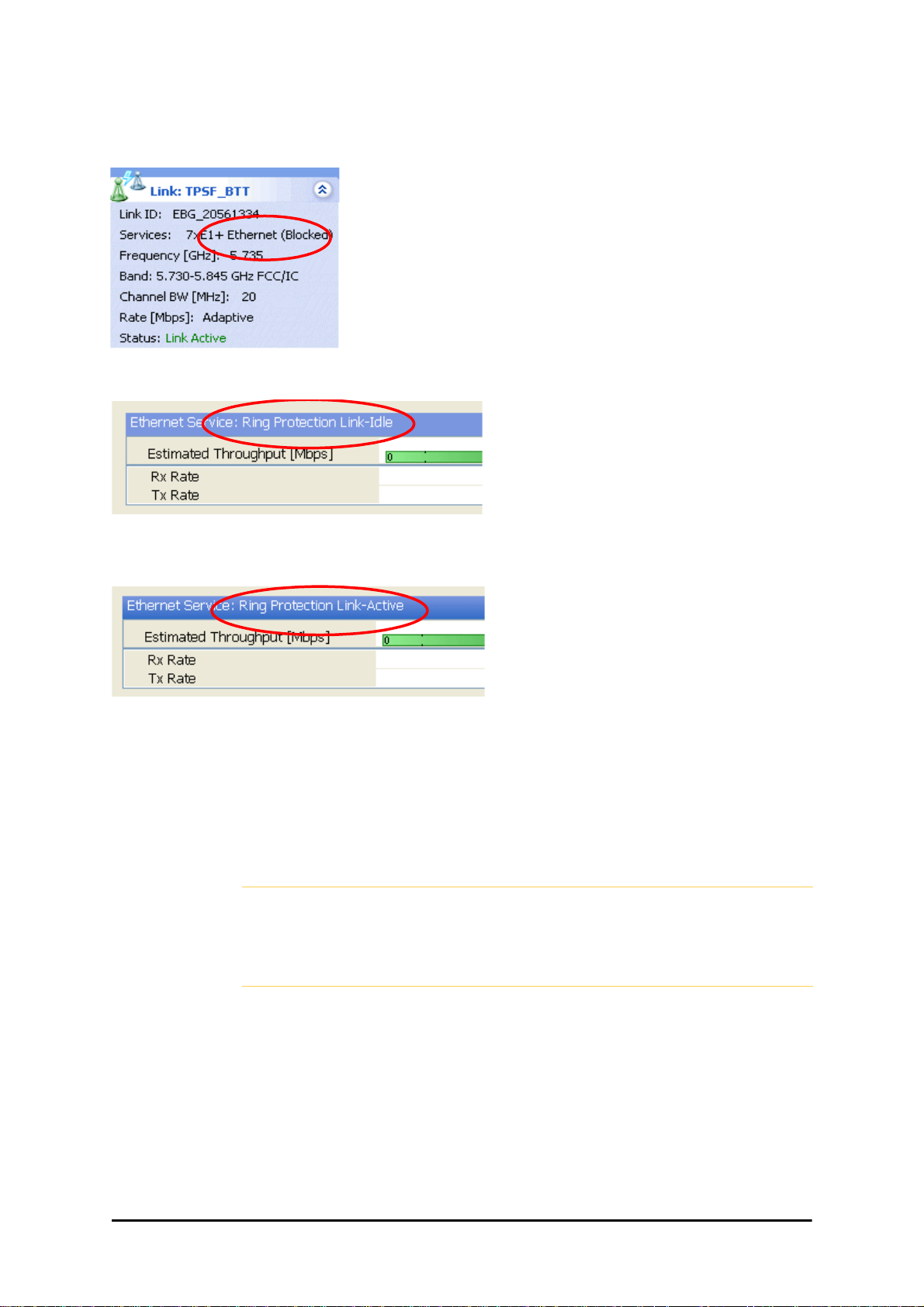
The RPL will be clearly indicated in the RADWIN Manager. In the Link status area on
the top left, you will see an Ethernet (Blocked) notice:
A Link-Idle message is displayed on the Ethernet Services Bar:
When the RPL cuts in as a result of a failure, the “Ethernet (Blocked)” notice disappears. The Ethernet Services Bar indicated that the RPL is active:
Upon restoration of the broken link, the RPL returns to idle status with the appropriate indications on the RADWIN Manager main window.
On the status bar for all ring member links, you will see the ring membership indicator icon:
• Do not configure more than one RPL. If you do, you will break the
Ring
Caution
• If you forget to configure one RPL in a Ring, you will introduce a loop
into your network
RADWIN 2000 User Manual Release 2.5.40 13-10
Page 32

Chapter 14
VLAN Functionality with
RADWIN 2000
VLAN Tagging - Overview
VLAN Terminology
Both the technical literature and the RADWIN Manager use the terms VLAN ID and VID interchangeably to denote a VLAN identification number.
VLAN Background Information on the WEB
The standards defining VLAN Tagging are IEEE_802.1Q and extensions.
For general background about VLAN see http://en.wikipedia.org/wiki/Virtual_LAN.
Background information about Double Tagging also known as QinQ may be found here:
http://en.wikipedia.org/wiki/802.1QinQ.
VLAN Tagging
VLAN tagging enables multiple bridged networks to transparently share the same physical
network link without leakage of information between networks:
Figure 14-1: Two network using the same link with tagging
RADWIN 2000 User Manual Release 2.5.40 14-1
Page 33

QinQ (Double Tagging) for Service Providers Chapter 14
IEEE 802.1Q is used as the encapsulation protocol to implement this mechanism over Ethernet networks.
QinQ (Double Tagging) for Service Providers
QinQ is useful for Service Providers, allowing them to use VLANs internally in their “tr ansport
network” while mixing Ethernet traffic from clients that are already VLAN-tagged.
Figure 14-2: Separating client data streams using double tagging
The outer tag (representing the Provider VLAN) comes first, followed by the inner tag. In
QinQ the EtherType = 0x9100. VLAN tags may be stacked three or more deep.
When using this type of “Provider Tagging” you should keep the following in mind:
• Under Provider Tagging, the system double-tags egress frames towards the Provider’s
network. The system adds a tag with a VLAN ID and EtherType = 0x9100 to all
frames, as configured by the service provider (Provider VLAN ID).
• The system always adds to each frame, tags with VLAN ID and EtherType = 0x9100.
Therefore,
• For a frame without a tag – the system will add a tag with VLAN ID and
EtherType = 0x9100 so the frame will have one tag
• For a frame with a VLAN tag – the system will add a tag with VLAN ID and
EtherType = 0x9100 so the frame will be double-tagged
• For a frame with a VLAN tag and a provider tag – the system will add a tag with
VLAN ID and EtherType = 0x9100 so the frame will be triple-tagged and so on
VLAN Untagging
VLAN Untagging means the removal of a VLAN or a Provider tag.
Port Functionality
The VLAN functionality is supported by all LAN and SFP ports in the IDU.
Each port can be configured how to handle Ethernet frames at the ingress direction (where
frames enter the IDU) and at the egress direction (where frame exit the IDU).
The configuration is independent at each port.
RADWIN 2000 User Manual Release 2.5.40 14-2
Page 34

Port Functionality Chapter 14
Ingress Direction
Table 14-1: Port settings - Ingress direction
Transparent The port ‘does nothing’ with regard to VLANs - inbound frames are left untouched.
Frames entering the port without VLAN or QinQ tagging are tagged with VL AN ID and Priorit y
are pre-configured by the user. Frames which are already tagged at ingress are not modified.
Tag
a. Priority Code Point (PCP) which refers to the IEEE 802.1p priority. It indicates the frame priority
level from 0 (lowest) to 7 (highest), which can be used to prioritize different classes of traffic
(voice, video, data, etc).
Egress Direction
Table 14-2: Port settings - Egress direction
a
, which
Transparent The port ‘does nothing’ with regard to VLANs - outbound frames are left untouched.
All frames are untagged.
Untag all
RADWIN 2000 User Manual Release 2.5.40 14-3
Page 35

Port Functionality Chapter 14
Table 14-2: Port settings - Egress direction (Continued)
Untags only frames tagged with one of the user defined VIDs. You can define up to eight VIDs per
port. Other frames are not modified.
Untag selected
VIDs
This setting allows for mutual filtering of multiple ingress tags not relevant at the egress end:
Filtered VLAN
IDs at egress
RADWIN 2000 User Manual Release 2.5.40 14-4
Page 36

VLAN Availability Chapter 14
Table 14-2: Port settings - Egress direction (Continued)
With Provider tagging, the system double- tags egress frames towards the provider’s network. All
frames are tagged QinQ with a VLAN ID, which is configured by the service provider (Provider VLAN
ID).
Provider
tagging
Provider
tagging without
filter
With this setting, ingress frames which are not tagged with the configured Provider VLAN ID are
blocked (filtered).
Note: Each port can be configured independently to a tagging mode. How e ver, only a single Provider
VLAN ID can be defined per IDU.
This setting functions like Provider tagging. However, all ingress frames are passed through.
VLAN Availability
VLAN is available for links using either WinLink 1000 or RADWIN 2000 radios. VLAN support
requires the use of IDU-Cs or new style IDU-Es.
VLAN Configuration Using the RADWIN Manager
VLAN IDs are used by RADWIN products in three separate contexts:
Management VLAN, Traffic VLAN and Ethernet Ring. It is recommended that
Caution
Disclaimer
RADWIN 2000 User Manual Release 2.5.40 14-5
you use different VLAN IDs for each context.
If you are not a VLAN expert, please be aware that incorrect VLAN
configuration may cause havoc on your network. The facilities described
below are offered as a service to enable you to get best value from your
RADWIN 2000 links and are provided “as is”. Under no circumstances does
RADWIN accept responsibility for network system or financial damages
arising from incorrect use of these VLAN facilities.
Page 37

Management Traffic and Ethernet Service Separation Chapter 14
Management Traffic and Ethernet Service Separation
You can define a VLAN ID for management traffic separation. You should configure the system to prevent conflicts as detailed below.
When configured for the default operational mode, a “Provider port” will handle ingress traffi c
as follows:
• Filters frames that are not tagged with the Provider VLAN ID
• Removes the Provider double tag
Therefore, if a port is configured for management tr affic separ ation by VL AN and as ‘Pro vider
port’, then the received management frames must be double tagged as follows:
• The outer tag has to be the Provider’s tag (so the frame is not filtered)
• The internal tag has to be management VLAN ID
To avoid mix-ups, best practic e is to:
• Separate the management and data ports
• Define only a data port with Provider function
All IDU-C and new style IDU-E models have two LAN ports so you can easily separate management and Ethernet service.
VLAN Tagging for Ethernet Service: Configuration
VLAN Configuration is carried out per site. It is up to you to ensure consistency between the
link sites. The discussion below is based on Site A however, it also applies to Site B.
To set up VLAN tagging for Ethernet service, enter Site Configuration for Site A, choose the
Ethernet tab and click the VLAN Configuration... button (Figure 8-15). The following window is displayed:
RADWIN 2000 User Manual Release 2.5.40 14-6
Page 38

VLAN Tagging for Ethernet Service: Configuration Chapter 14
Figure 14-3: VLAN tag settings
If you are using a new style IDU-E, the SFP row will not appear.
Note
The choices for Ingress Mode are -
Figure 14-4: VLAN: Ingress modes
The two choices correspond respectively to the two rows of Table 14-1. Choosing Tag
causes the VLAN ID and VLAN Priority fields to become available:
RADWIN 2000 User Manual Release 2.5.40 14-7
Page 39

VLAN Tagging for Ethernet Service: Configuration Chapter 14
Figure 14-5: VLAN: Ingress mode - setting VLAN ID and Priority
Throughout this chapter, all VLAN IDs must be between 1 and 4094,
inclusive. All VLAN priorities must be between 0 and 6, inclusive. The values
Note
The choices for Egress Mode are -
entered are range-checked. If for example, you enter a VLAN ID of 4095,
then 4094 will be reflected back.
Figure 14-6: VLAN: Egress modes
The five non-transparent choices correspond respectively to the five rows of Table 14-2 in
the order, row 1, 2, 4, 5, 3.
The first two choices, Transparent and Untag all require no further action.
Untag selected VIDs causes the eight VLAN ID fields to become available:
Figure 14-7: Untagging selected VIDs
You ma y nominate up to eight VIDs for untagging; beyond simple r ange checking, there is no
other validation.
Both Provider tagging and Provider tagging without filter enable the Provider
parameters fields:
Figure 14-8: Provider parameters
RADWIN 2000 User Manual Release 2.5.40 14-8
Page 40

VLAN Tagging for Ethernet Service: Configuration Chapter 14
There is of course only one Provider VLAN ID. It is most likely yours, as the Provider!
Filtered VLAN IDs enables you to filter and block only frames tagged with one of the user
defined VIDs. You can define up to eight VIDs per port. Other frames are not modified and
are forwarded transparently.
When you are finished, remember to click OK (Figure 14-3) to save your entries.
RADWIN 2000 User Manual Release 2.5.40 14-9
Page 41

Chapter 15
Software Upgrade
What is the Software Upgrade Utility?
The RADWIN Manager provides a Software Upgrade Utility (SWU) to upgrade the software
(firmware) of installed ODUs in a network. The update files may be located anywhere accessible by the operator.
The SWU provides for:
• Prior backup of the current files prior to upgrade
• Upgrade from a list
• Delayed upgrade
• Various ODU reset options
The default location of the software files is in the installation area, and can be used to restore
factory defaults.
The following procedure is generic to all RADWIN radio and GSU products.
Note
Upgrading an Installed Link
To upgrade software for a link:
1. In the RADWIN Manager main menu, click Tools | Software Upgrade ... The following detached window appears
RADWIN 2000 User Manual Release 2.5.40 15-1
Page 42

Upgrading an Installed Link Chapter 15
Figure 15-1: Software Upgrade Utility - Main window
The default sites shown in the Software Upgrade list panel belong to the currently
link. The list may be empty if you are running the RADWIN Manager “offline”.
What follows about adding sites manually or from a list file, assumes that all
sites to be upgraded are of the same type - either WinLink 1000 or RADWIN
Warning
2. Click Add Site to add additional sites for upgrade.
2000. but not both. This will not work with a mixed list.
Figure 15-2: Add site options
Click Add Single Site for one site only:
Figure 15-3: Adding a single site for upgrade
RADWIN 2000 User Manual Release 2.5.40 15-2
Page 43

Upgrading an Installed Link Chapter 15
Enter the IP address of the site, the Community strings (Default:
man
, respectively) and then click OK. The site will appear in the Software Upgrade
list box. For example if we add the site at IP address 192.168.2.101, the SWU main
window of Figure 15-1 looks like this:
public
and
net-
Figure 15-4: Single site added for upgrade
The list can be cleared using the Clear All button.
As an alternative to adding sites one at a time, you can add sites from a prepared list
using the Add from File option in Figure 15-2. The list has the following format:
<IP address>,<Read-Only community>,<Read-Write community>
Here is an example:
192.168.1.101,public,netman
192.168.1.102,public,netman
192.168.2.101,public,netman
192.168.2.102,public,netman
3. Having created an update list, click Upgrade Package to chose the relevant files.
The default files are located in the SWU subdirectory in the RADWIN Manager installation area. They are currently named SWU_1k.swu and SWU_2k.swu. You may
have to find them elsewhere, depending on your system.
4. You make limited changes to the list by right-clicking any line:
Figure 15-5: Software Upgrade site options
RADWIN 2000 User Manual Release 2.5.40 15-3
Page 44

Upgrading an Installed Link Chapter 15
5. To back up your existing system, check Backup device software check-box. Then
click the button for a standard file dialog. The default location is the My Docu-
ments directory on the managing computer or the last backup directory you used.
The backup here is the same as that in page 8-32, and serves the same
purpose. It provides a fallback if the upgrade proves problematic.
Note
6. In addition to the previous step, you may opt to perform a delayed upgrade. Check
the Delayed Upgrade box, and enter the date and time for the delayed upgrade.
7. The radio buttons on the right determines how your sites should be reset. Bear in
mind that on the one hand, a reset involves a service interruption, but on the other
hand, the software upgrade will not become effective until after the reset is carried
out.
8. Click Start Upgrade to commence the process. For an immediate upgrade you will
be able to observe the upgrade progress fr om the green progress bars:
Figure 15-6: Software upgrade in progress - Note the stop button
Figure 15-7: Software upgrade completed successfully
9. Click Close to exit.
10. If you requested a delayed upgrade, a notice like this will appear in the SWU title
bar:
RADWIN 2000 User Manual Release 2.5.40 15-4
Page 45

Software Update for GSUs Chapter 15
If one or both sites fail to update, a warning notice will be displayed.
If one site of a link updates but the other fails, you should correct the
Caution
problem and update the second site as soon as possible. If you do not,
following the next reset of the updated site, you could experience a link
software mismatch which may affect service. See page 9-3 for details.
Software Update for GSUs
All GSUs in a distributed site can be updated simultaneously. Use an IP list as described
above.
RADWIN 2000 User Manual Release 2.5.40 15-5
Page 46

Chapter 16
FCC/IC DFS Installation
Procedure
FCC/IC 5.4/5.3 GHz Links: Background
The FCC/IC regulation for 5.4/5.3 GHz allows unlicensed wireless data equipment, provided
that it does not interrupt radar services. If radar activity is detected, the equipment must
automatically change frequency channel. This feature is termed Dynamic Frequency Selection
(DFS). According to the standard, a channel with active radar is prohibited from use for 30
minutes. Before using a channel for transmission, the radio equipment must probe it for radar
signals for a period of 60 seconds.
RADWIN radio products support DFS as well as ACS.
An immediate consequence of the FCC/IC regulation for 5.4/5.3 GHz is that the standard
method of link installation using a single default fixed installation channel, cannot be used.
Instead of the installation procedure of Chapter 5, a link activation method is used.
The ODUs are either supplied from the factory ready for use at 5.4 GHz or 5.3 GHz FCC/IC or
alternatively, they can be set up for these bands using the RADWIN Manager.
The following procedure is generic to all relevant RADWIN radio products.
What you see on your running RADWIN Manager may differ in some details
Note
from the screen captures used to illustrate this chapter.
FCC/IC 5.4/5.3 GHz Link Activation
To Activate a FCC/IC 5.4/5.3 GHz Link:
1. Install RADWIN Manager software as usual.
2. Connect the PC to the IDU-ODU pair to be used as the local site.
3. Run the RADWIN Manager and log in as Installer. You will see the following window:
RADWIN 2000 User Manual Release 2.5.40 16-1
Page 47
FCC/IC 5.4/5.3 GHz Link Activation Chapter 16
Figure 16-1: Activating an ODU - Inactive link
When the Manager Main Screen is displayed it appears with the Link Status label red
and showing Inactive.
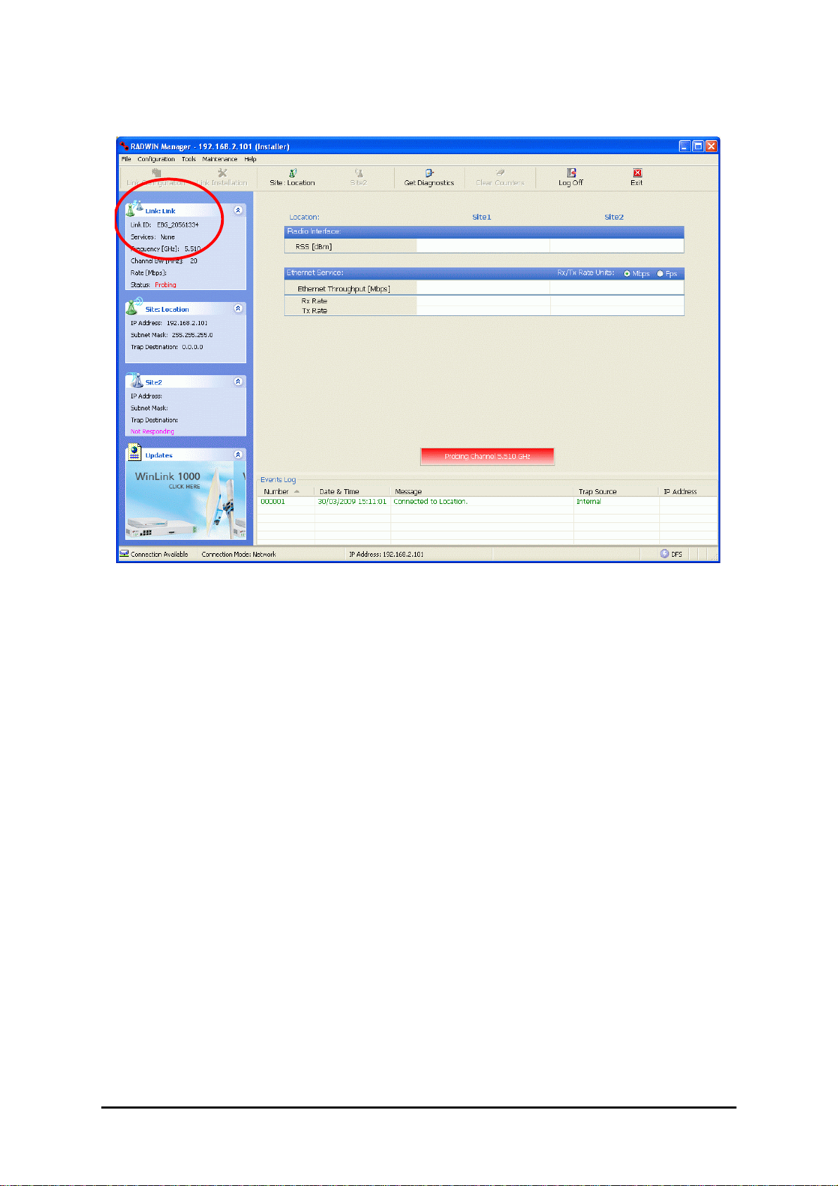
4. Click Site:Location | Air Interface for the logged in site.
5. The Air Interface dialog box opens:
Figure 16-2: Air Interface dialog box
6. Enter the Link ID and note it for use with the second site of the link.
7. Check the Master radio button.
RADWIN 2000 User Manual Release 2.5.40 16-2
Page 48
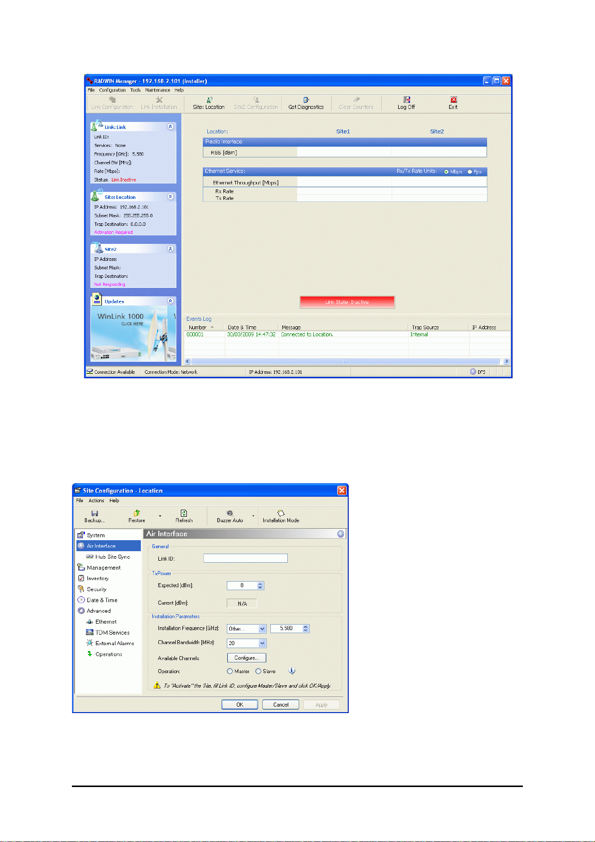
FCC/IC 5.4/5.3 GHz Link Activation Chapter 16
8. Click OK. The following window appears:
Figure 16-3: The local ODU after activation - Probing
Notice that the Link ID is shown in the Link details pane (circled).
9. Repeat the above procedure for the remote ODU, ensuring that in the Air Interface
window, that you enter exactly the same Link ID, but this time that you check the
Slave radio button.
If both ODUs are powered up, after a minute or so a link will be established. If you
are still connected to the remote site (from the previous steps), the window of
Figure 16-3 will look like this:
RADWIN 2000 User Manual Release 2.5.40 16-3
Page 49

FCC/IC 5.4/5.3 GHz Link Configuration Chapter 16
Figure 16-4: Both sites activated and awaiting configuration
FCC/IC 5.4/5.3 GHz Link Configuration
The Configuration procedure may be carried out from either site using the Configuration wizard as shown in Chapter 7.
Both sites in a FCC/IC 5.4/5.3 GHz Link must be configured
Note
The only difference is in the Channel Settings window:
identically.
RADWIN 2000 User Manual Release 2.5.40 16-4
Page 50

FCC/IC 5.4/5.3 GHz Link Configuration Chapter 16
Figure 16-5: Channel Select dialog box - ACS permanently enabled
ACS cannot be disabled.
Note
Upon completion of the wizard, the Site configuration dialogs can be used in the usual way.
Once operational, the RADWIN Manager window is the same as for othe r radio equipment
models.
Here is the RADWIN Manager main window upon completion of the wizard:
RADWIN 2000 User Manual Release 2.5.40 16-5
Page 51

FCC/IC 5.4/5.3 GHz Link Configuration Chapter 16
Figure 16-6: FCC/IC 5.4/5.3 GHz operational
RADWIN 2000 User Manual Release 2.5.40 16-6
Page 52

RADWIN 2000
Broadband Wireless Transmission System
USER MANUAL
RELEASE 2.5.40
Part 4: Field Installation
Topics
UM 2000-2540/02.11
Page 53

Chapter 17
Pole and Wall Installation
ODU Mounting Kit Contents
Table 17-1: Bill of Materials: ODU mounting kit
Item Qty
Large Clamp (see Figure 17-1)1
Small Clamp (see Figure 17-2)1
Arm (see Figure 17-3)1
Screw hex head M8x40 4
Screw hex head M8x70 2
Washer flat M8 4
Washer spring M8 3
M8 Nuts 2
Figure 17-1: Large Clamp Figure 17-2: Small Clamp Figure 17-3: Arm
RADWIN 2000 User Manual Release 2.5.40 17-1
Page 54

Mounting an ODU on a Pole Chapter 17
Mounting an ODU on a Pole
Figure 17-4: Mounting on a pole
RADWIN 2000 User Manual Release 2.5.40 17-2
Page 55

Mounting an ODU on a Wall Chapter 17
Mounting an ODU on a Wall
Figure 17-5: Mounting on a Wall
RADWIN 2000 User Manual Release 2.5.40 17-3
Page 56

Mounting an External Antenna Chapter 17
Mounting an External Antenna
Optional external antennas can be mounted on a pole. The external mounting kit varies
according to the specific antenna model.
Mounting a Connectorized ODU Horizontally
What follows applies to both WinLink 1000 and RADWIN 2000 with obvious differences.
An ODU may be mounted horizontally as shown in Figure 17-6.
To mount an ODU horizontally, observe the following cautions:
1. To ensure your warranty rights for horizontally installed ODUs, make sure that the
four ports ANT1, ANT2, HSS and ODU are firmly secured or moisture sealed with the
supplied caps.
2. Further, ensure that cables are connected using a “water nose” as shown in
Figure 17-6.
Figure 17-6: Mounted ODUs with correct “water nose”
Do not do this:
Figure 17-7: Incorrectly mounted ODU (No “water nose”)
3. If you attach an external PoE device near the ODU, the same considerations apply.
RADWIN 2000 User Manual Release 2.5.40 17-4
Page 57

Chapter 18
Lightning Protection and
Grounding Guidelines
Meticulous implementation of the guidelines in this chapter will provide best protection
against electric shock and lightning.
100% protection is neither implied nor possible.
Warning
This chapter is at best a guide. The actual degree of lightning protection
Note
The RADWIN Lightning Protection System consists of the following components:
required depends on local conditions and regulations.
• Grounding for the antenna coax cable
• Grounding for each IDU and ODU
• External Primary Surge Suppressor units and grounding for the outdoor cable
• Internal ESD protection circuits over the Power/Telecom lines
Grounding for Antenna Cable
A Grounding Kit must be connected to the coax antenna cable and reliably grounded. The
grounding kit is an Andrew Type 223158-2 (www.andrew.com). See Figure 18-1 below.
RADWIN 2000 User Manual Release 2.5.40 18-1
Page 58

Grounding for Indoor/Outdoor Units Chapter 18
Figure 18-1: Grounding antenna cables
Grounding for Indoor/Outdoor Units
ODU Grounding
RADWIN Lightning Protection System uses a Shielded CAT-5e cable to interconnect the Outdoor (ODU) and Indoor (IDU) units.
However, this shielding does not provide a good lightning discharge path, since it can not tolerate the high Lightning Current surges.
To provide an alternate Lightning Discharge path, the ODU and antenna grounding posts
should be connected to ground point by a 10 AWG short copper wire.
The device should be permanently connected to ground.
RADWIN 2000 User Manual Release 2.5.40 18-2
Page 59

IDU Grounding Chapter 18
IDU Grounding
The IDU’s grounding post should be connected to the internal ground point, using a grounding wire of at least 10 AWG. The grounding wire should be connected to a grounding rod or
the building grounding system.
The device should be permanently connected to ground.
External Lightning Surge Suppressors and Grounding
A Grounding Kit and Surge Arrestor Unit must be located near the ODU and properly
grounded as illustrated in Figures 18-2 and 18-3 below:
RADWIN 2000 User Manual Release 2.5.40 18-3
Page 60

External Lightning Surge Suppressors and Grounding Chapter 18
Figure 18-2: Grounding a typical pole installation
RADWIN 2000 User Manual Release 2.5.40 18-4
Page 61

External Lightning Surge Suppressors and Grounding Chapter 18
Figure 18-3: Grounding a typical wall installation
The next figure shows a close-up of the rear of grounded ODU:
Figure 18-4: ODU Surge Suppressor and grounding
RADWIN 2000 User Manual Release 2.5.40 18-5
Page 62

External Lightning Surge Suppressors and Grounding Chapter 18
The Transtector protection circuits shown in Figure 18-5 below, utilize silicon avalanche
diode technology. The unit consists of an outdoor rated NEMA 3R type enclosure with easy
mounting flanges, ground stud attachment and easy wiring.
The ALPU-POE features RJ-45 protection circuits f or the ODU- IDU data pair s (pins 1,2 & 3,6)
and DC power (pins 4,5 & 6,7 with the pairs bonded).
The unit is designed to be wall mounted. An optional set of bracket is available from the manufacturer to allow a wide range of pole mount applications. A dedicated ground stud is provided inside the unit that must be bonded to the nearest grounding system (or Master Ground
bar) for proper surge protection.
The system wiring is installed with RJ-45 type connectors that can feed directly into the chassis without having to cut, splice or route through awkward strain relief holes.
Figure 18-5: Transtector’s Surge Suppressor
To mount the lightning protection devices:
1. Mount the device as close to the ODU as possible. Mount the unit so that the cable
connectors are at the bottom (to prevent water from penetrating), with the strain
reliefs facing the ground.
2. Remove the cover by unscrewing the front of the unit.
3. Mount the unit to an outside surface using the two mounting holes.
4. Connect the ODU-IDU cable using the RJ-45 jack.
5. Connect one cable between the ODU and the suppressor using an RJ-45 jack.
6. Connect the suppressor’s ground stud to a grounding point. Use the appropriate wire
gauge and type, keeping the wire as short as possible, less than 1m (3’), between
the stud and the site grounding point.
7. Replace the cover.
There may also be regulatory requirements to cross bond the ODU-IDU CAT5e cable at regular intervals up the mast. This may be as frequent as every
Note
10 meters (33 feet).
RADWIN 2000 User Manual Release 2.5.40 18-6
Page 63

External Lightning Surge Suppressors and Grounding Chapter 18
A second Surge Arrestor Unit should be mounted at the building entry point and must be
grounded, as shown in Figure 18-3 above.
To mount the lightning protection at the building entry point:
1. Mount the device outside the building, located as near as possible to the entrance of
the CAT-5e ODU-IDU cable. Mount the unit so that the cable connectors are at the
bottom (to prevent water from penetrating), with the str ain reliefs facing the ground.
2. Remove the cover by unscrewing the front of the unit.
3. Mount the unit to an outside surface using the two mounting holes.
4. Connect the ODU-IDU cable using the RJ-45 jack.
5. Connect one cable between the IDU and the suppressor using an RJ-45 jack.
6. Connect the suppressor’s ground stud to a grounding point. Use the appropriate wire
gauge and type, keeping the wire as short as possible, less than 1m (3’), between
the stud and the site grounding point.
7. Replace the cover
Figure 18-6: Surge Suppressor and grounding at building entry point
RADWIN 2000 User Manual Release 2.5.40 18-7
Page 64

Internal ESD Protection circuits Chapter 18
Internal ESD Protection circuits
RADWIN equipment is designed to meet the ETSI/FCC/Aus/NZ/CSA EMC and Safety requirements. To fulfill these requirements, the system's Telecom lines at the ODU/IDU are Transformer-isolated and include internal ESD (Electro-Static-Discharge) Protection circuits.
RADWIN 2000 User Manual Release 2.5.40 18-8
Page 65

Chapter 19
Preloading an ODU with
an IP Address
Why this is Needed?
All ODUs supplied by RADWIN come pre-configured with an IP address of 10.0.0.120. For use
in a network, the ODUs must be configured with suitable static IP addresses. The method for
doing this under office conditions is set out in Chapter 5.
There are two situations under which ODUs may need to be pre-loaded with an IP address
prior to installation to a link:
• Changing an individual ODU in the field
• Preparing a large number of ODUs in a warehouse prior to deployment in the field,
according to a network installation plan.
This chapter explains how do this.
Required Equipment
The minimal equipment required to pre-load an ODU with an IP address is:
• Laptop computer (managing computer) satisfying the requirements of Table 4-1
• An installed copy of the RADWIN Manager
• A PoE device
• A crossed Ethernet LAN cable
• An IDU-ODU cable
• If you have connectorized ODUs, two N-type RF terminators
Do not carry out this procedure using a multi homed managing computer
also connected to a network. It will flood the network with broadcast
Caution
RADWIN 2000 User Manual Release 2.5.40 19-1
packets. Further, it will throw any other links on the network into Installation
mode.
Page 66

The procedure Chapter 19
The procedure
The following procedure is generic to all RADWIN radio products. What you
see on your running RADWIN Manager may differ in some details from the
Note
To Preolad an ODU with an IP address:
1. Using the IDU-ODU cable, connect the PoE device to the ODU, ensuring that the
cable is plugged into the PoE port marked P-LAN-OUT.
2. For connectorized ODUs, screw the RF terminators into the two antenna ports.
screen captures used to illustrate this chapter.
A powered up ODU emits RF radiation from the antenna port (or connected
antenna). When working with a powered up connectorized ODU, always use
RF terminators.
Warning
3. Connect the Poe device to AC power.
4. Using a crossed LAN cable, connect the LAN-IN port of the PoE device to the Ethernet
port of the managing computer. The ODU will commence beeping at about once per
second, indicating correct operation.
5. Launch the RADWIN Manager.
6. At the log on window, choose Local Connection.
For an ODU with an integrated antenna, ensure that the antenna is always
directed away from other people.
Figure 19-1: Log on Window for Local Connection
7. Enter the default password,
main window appears:
RADWIN 2000 User Manual Release 2.5.40 19-2
admin
. After a few moments, the RADWIN Manager
Page 67

The procedure Chapter 19
Figure 19-2: Opening RADWIN Manager window prior to installation
8. Click the un-grayed Site:Location button. The following dialog window appears:
Figure 19-3: Configuration Dialog Box
9. Click the Management item in the left hand panel. The following window is presented:
RADWIN 2000 User Manual Release 2.5.40 19-3
Page 68

The procedure Chapter 19
Figure 19-4: Management Addresses - Site Configuration dialog box
10. Enter the IP Address, Subnet Mask and Default Gateway as requested. For example,
the ODU used here is to be configured as follows:
Figure 19-5: ODU with IP Addressing configured
11. Click OK. You are asked to confirm the change:
Figure 19-6: Confirmation of IP Address change
RADWIN 2000 User Manual Release 2.5.40 19-4
Page 69

The procedure Chapter 19
12. Click Yes to accept the change. After about half a minute the changes will be registered in the ODU. On the left hand panel of the main window, you will see the new
IP configuration for the ODU.
Figure 19-7: Main Window after IP Address change
Some additional things you may want to do now:
•Go to Site Installation | Air Interface. You can enter a Link ID
Note
13. Click Cancel to leave the open Management dialog. You may now exit the RADWIN
Manager, or connect to another ODU. If you choose to connect to another ODU,
after about a minute, the main window of the RADWIN Manager will revert to that
shown in Figure 19-2 above. In any event, power down the changed ODU; your
changes will take effect when you power it up again.
Don’t forget to remove the RF terminators from a connectorized ODU after
powering it down.
and change the Installation Frequency and Channel Bandwidth.
• If you log on as Installer, you can change the default band (Chapter
20).
Note
RADWIN 2000 User Manual Release 2.5.40 19-5
Page 70

Tip: How to Recover a Forgotten ODU IP Address Chapter 19
Tip: How to Recover a Forgotten ODU IP Address
If you have an ODU with lost or forgotten IP address, use the abov e pro cedure to log o n to it
using Local Connection. The IP address will appear in the left hand status area:
Figure 19-8: Existing IP address displayed after log-on with Local Connection
RADWIN 2000 User Manual Release 2.5.40 19-6
Page 71

Chapter 20
Changing the Factory
Default Band
Why this is Needed
All ODUs supplied by RADWIN come with pre-configured with a factory default productdependent band according to the ODU part number.
For ODUs supporting Multi-band, it may be changed using the procedure in this chapter. The
procedure is generic, applying to all ODUs with the Multi-band feature.
• If for some reason the default band needs to be changed, it should
be done before link installation.
Caution
• Use of an incorrect band may be in violation of local regulations.
Required Equipment
The minimal equipment required to change an ODU default band is:
• Laptop computer (managing computer) satisfying the requirements of Table 4-1.
• An installed copy of the RADWIN Manager
• A PoE device
• A crossed Ethernet LAN cable
• An IDU-ODU cable
The procedure
The following procedure is generic to all relevant RADWIN radio products.
What you see on your running RADWIN Manager may differ in some details
Note
To change the factory default band:
1. Using the IDU-ODU cable, connect the PoE device to the ODU, ensuring that the
cable is plugged into the PoE port marked P-LAN-OUT.
from the screen captures used to illustrate this chapter.
RADWIN 2000 User Manual Release 2.5.40 20-1
Page 72

The procedure Chapter 20
2. Connect the Poe device to AC power.
3. Using a crossed LAN cable, connect the LAN-IN port of the P oE device to the Ethernet
port of the managing computer. The ODU will commence beeping at about once per
second, indicating correct operation.
4. Launch the RADWIN Manager.
5. Log on as Installer.
Figure 20-1: Becoming Installer
6. Enter the default password,
main window appears:
wireless
. After a few moments, the RADWIN Manager
RADWIN 2000 User Manual Release 2.5.40 20-2
Page 73
The procedure Chapter 20
Figure 20-2: Opening RADWIN Manager window prior to band change (default circled)
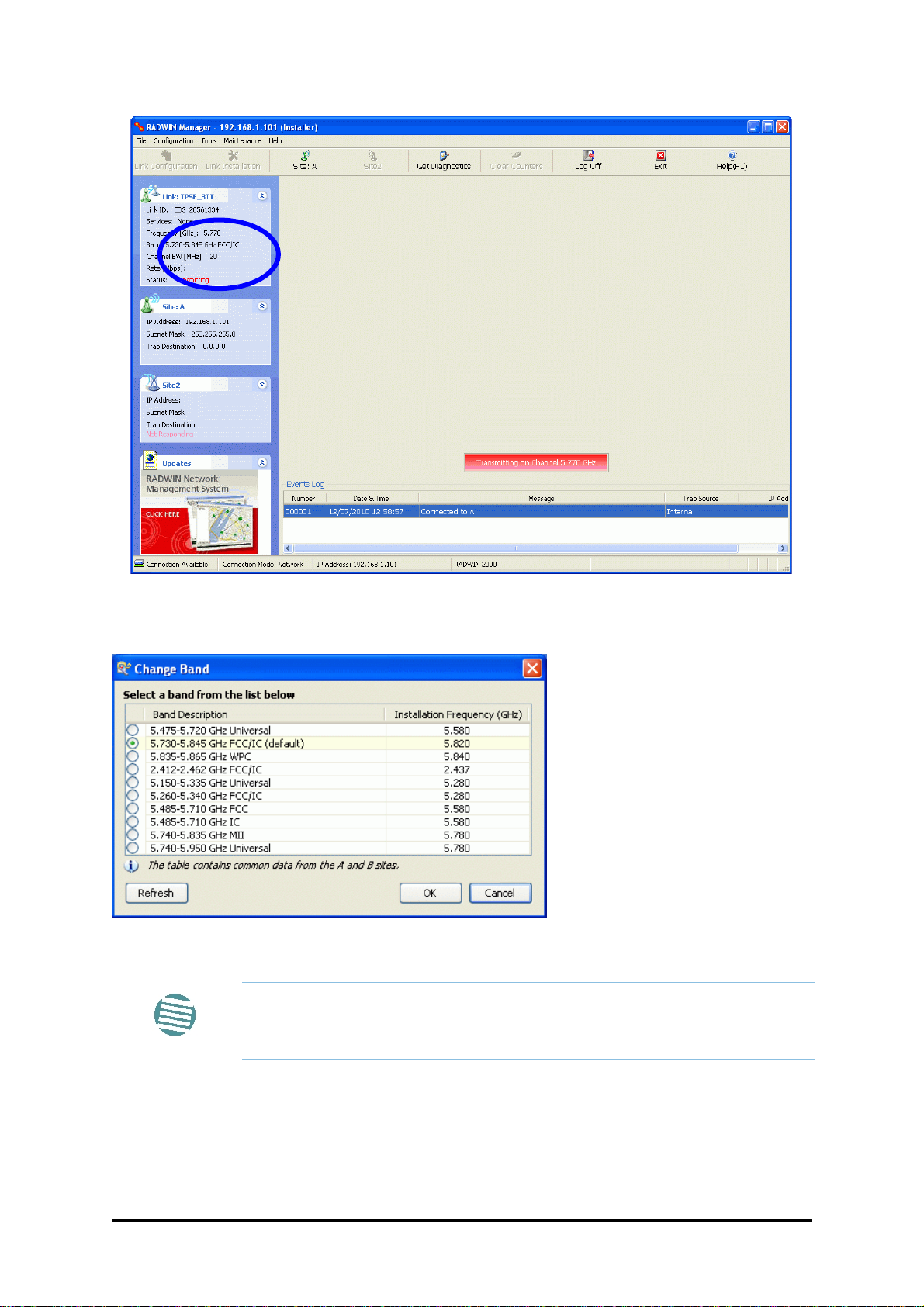
7. Click Tools | Change Band. The following window appears:
Figure 20-3: Change Band dialog
The bands appearing in Figure 20-3 are product dependent. To see which
bands are available for your product, check your product Inventory (see
Note
Figure 8-8) and then consult RADWIN Customer Support.
8. Click the band required:
RADWIN 2000 User Manual Release 2.5.40 20-3
Page 74

The procedure Chapter 20
Figure 20-4: A different band selected
9. The Change Band warning is displayed. Click Yes to continue.
Figure 20-5: Change Band confirmation
The change, which may take some time, is carried out:
The result is reflected in the RADWIN Manager main window:
RADWIN 2000 User Manual Release 2.5.40 20-4
Page 75

Changing Band for DFS Chapter 20
Figure 20-6: Main Window after band change - new band circled
If you carry out this operation on a link, the band is effective on both sites
Note
and you are placed in installation mode.
Changing Band for DFS
Changing to a DFS band is similar to the foregoing procedure.
As soon as you establish a link using a DFS band, you are offered Configuration only in the
main menu. Installation mode is disabled.
Special Products or Features: Entering a License Key
If you go to the Operations window as Installer (Figure 20-7), you will see a provision for
entering a license key. Should you ever require such a key, the procedure is as follows:
To enter a License key:
1. Log on as Installer (as for the previous procedure).
2. Click the Site:Location tool bar button from the main tool bar.
RADWIN 2000 User Manual Release 2.5.40 20-5
Page 76

Provisions for Licensed 3.X and 2.5 GHz Bands Chapter 20
Figure 20-7: Using the Operations window to enter a license key
3. Enter your license key and click Activate.
4. When it is accepted, click Cancel.
License keys, where appropriate, are obtainable from RADWIN Customer
Support.
Note
Provisions for Licensed 3.X and 2.5 GHz Bands
Overview
3.X Bands
The new RADWIN 2000 C and RADWIN 2000 X series add additional bands in the 3.X GHz
range to those in Release 2.5.00. The new supported bands fall into two categories: The first
category consists of those falling under the ubiquitous FCC, IC or ETSI regulation. The second
category is referred to as RADWIN Universal bands. These bands are known to be regulated
but the numerous combinations of regulation and location preclude specific support.
Release 2.5.40 introduces support for the band 3.3-3.8 GHz as follows:
• FCC part 90 subpart Z and IC RSS-197 supporting 3.650-3.700 GHz
• 3.650 -3.675 GHz in Restricted mode
• Hardware ready for the Unrestricted Mode band operating in all 50 MHz of the
3.650-3.700 GHz band
• IC RSS-192 supporting 3.475 – 3.650 GHz
• ETSI 3.4 -3.7 GHz split into three sub-bands, 3.650-3.675 GHz, 3.475-3.650 GHz and
3.590-3.710 GHz
RADWIN 2000 User Manual Release 2.5.40 20-6
Page 77

Terminology Recap Chapter 20
• RADWIN Universal 3.300-3.800 GHz.
Integrated and connectorized products are available. All of them are multiple band with the
default band being 3.650-3.675 GHz other than the ETSI 3.4 - 3.7 GHz models.
The new products may be operated under 5, 10 and 20 MHz channel bandwidths and are
broadly compatible with the full feature set of RADWIN 2000.
To meet regulatory requirements, a somewhat different procedure is required to set up links
using these bands.
2.5GHz Bands for BRS/EBS
The rationale for these bands and relevant details are described in Chapter 24. The installation method ids the same as for other licenced FCC bands as described below.
Terminology Recap
• 3.X Universal bands refer to RADWIN Universal bands as described above
• 3.X or 3.X GHz refers to the frequency range 3.300 – 3.800GHz
•A 3.X ODU is an ODU pre configured to operate in the 3.X GHz licensed bands
•A 3.X Link in a RADWIN 2000 link using a pair of 3.X ODUs
• High Resolution Bands - Channel minimum step is 250 KHz. Applies to 3.475 -
3.650 GHz IC RSS-192, 3.4 -3.7 GHz ETSI and the 3.3 - 3.8 GHz Universal band.
• Low Resolution Bands - Channel minimum step is 1 MHz. Applies to FCC regulations in the 3.650-3.675 GHz band.
• Inactive Mode - An ODU is powered up, in communication with a managing computer but not transmitting. It is required where regulation does not permit the use of
RADWIN’s default Installation Mode f requency and channel bandwidth. The ODU ma y
transmit using the licensed or registered band, channel bandwidth and permitted Tx
power.
• Regular Mode - The usual default Installation Mode
Regulatory Considerations for 3.650-3.675 GHz FCC/IC part 90 sub
part Z
Restricted Mode
The band is supported in accordance with 3.650-3.675 FCC/IC part 90 subpart Z:
RADWIN Ltd. conforms to FCC DA 07-4605 (November 14, 2007) FCC-certified with FCC-ID:
Q3KRW2030 and supporting the following equipment requirements:
“Restricted contention protocols can prevent interference only with other devices incorporat -
ing the same or similar protocols. Equipment using a restricted protocol can operate only on
the lower 25 megahertz (3650-3675 MHz)."
RADWIN 2000 User Manual Release 2.5.40 20-7
Page 78

Regulatory Considerations for 3.650-3.675 GHz FCC/IC part 90 sub part Z Chap-
Transmission power options
Table 20-1shows the extent of compliance by RADWIN 2000 C products to FCC/IC power
limits, having regards to antenna type and transmission power options.
Table 20-1: FCC/IC compliance by antenna and transmission power
Measured
Frequency Power
Antenna
21dBi INT
21dBi EXT (22dBi-
1dB feeder)
24dBi EXT (25 -
1dB feeder loss)
Nominal
CBW
5 MHz
10 MHz
20 MHz
5 MHz
10 MHz
20 MHz
5 MHz
10 MHz
20 MHz
Low Center
Frequency
Channel
[MHz]
3653 3672 11.14 14.14 35.14
3655 3670 14.46 17.46 38.46
3660 3665 17.36 20.36 41.36
3653 3672 11.14 14.14 35.14
3655 3670 14.46 17.46 38.46
3660 3665 17.36 20.36 41.36
3653 3672 8.65 11.65 35.65
3655 3670 11.36 14.36 38.36
3660 3665 13.73 16.73 40.73
High Center
Frequency
Channel
[MHz]
Max
Conducted Tx
Power per
Pole [dBm]
Total
Conducted
Max Tx Power
[dBm]
Max EIRP
[dBm]
Higher Transmission Power Options and Restrictions:
Table 20-2 defines the maximum transmission power and EIRP limits for the specified fre-
quency and channel bandwidths.
It specifies the power limits to be used by the operator when assigning center frequencies.
Table 20-2: Higher T ransmission Power Limits
Nominal
CBW
5 MHz
10 MHz
20 MHz
Low Center
Frequency
Channel [MHz]
3653 3672 15.60 18.60 35.60
3655 3670 18.69 21.69 38.69
3656 3669 22.00 25.00 38.50
3660 3665 21.18 24.18 41.18
3661 3664 22.60 25.60 39.10
High Center
Frequency
Channel [MHz]
Max Conducted
Tx Power per
Pole [dBm]
Total Conducted
Max Tx Power
[dBm]
Max EIRP
[dBm]
RADWIN 2000 User Manual Release 2.5.40 20-8
Page 79

Band Splitting for ETSI 3.4 - 3.7GHz Chapter 20
Availability Summary for FCC/IC and Universal 3.X GHz
Table 20-3: Availability for FCC/IC and Universal 3.X GHz
Products series
RADWIN 2000 C
RADWIN 2000 X
Occupied
Band
GHz
3.650-3.675 FCC/IC Regular
3.475-3.650 IC
3.300-3.800 Universal Unlimited
3.650-3.675 FCC/IC Regular
3.475-3.650 IC
3.300-3.800 Universal Unlimited
Regulation Mode
Inactive 250
Inactive 250
Channel
Bandwidth
MHz
5, 10, 20
5
Max Tx
Power
dBm
25
25
Frequency
Step
KHz
1000
1000
Band Splitting for ETSI 3.4 - 3.7GHz
The ETSI 3.4 - 3.7GHz band is split into three sub-bands reflecting the different Max Tx Power
allowed in each one. The details are shown in below:
Table 20-4: Band split for ETSI 3.4-3.7GHz
Products series
Occupied
Sub-Band
GHz
3.403-3.490 3.413-
Center
Frequency
GHz
3.480
Mode
Channel
Bandwidth
MHz
Max Tx
Power
dBm
16
Frequency
Step KHz
RADWIN 2000 C
RADWIN 2000 X
3.480-3.600
3.590-3.710
3.403-3.490 3.413-
3.590-3.710
3.600
3.480-3.600
3.600
-3.700 25(‡)
3.480
-3.700 25(‡)
Inactive 5, 10, 20
Inactive 5
23(†)
16
23(†)
2503.470-3.610
2503.470-3.610
(†) The 3.480 GHz frequency is overlaped, occuring in two different bands
as shown. If you wish to use the 3.480 GHz frequency, you should set Max
TX Powerto 16 dBm.
Note
(‡) The 3.600 GHz frequency is overlaped, occuring in two different bands
as shown. If you wish to use the 3.600 GHz frequency, you should set Max
TX Powerto 23 dBm.
Using he RADWIN Manager to set up a 3.X or BRS Link
Inactive and Active Mode
Low Resolution Band 3.X ODUs may be installed and configured in the usual way.
What follows applies to High Resolution Band ODUs.
To ensure compliance with the relevant license, 3.X ODUs for IC, ETSI and Universal must be
configured from an inactive mode where the ODU is powered up, in communication with a
managing computer but not transmitting.
RADWIN 2000 User Manual Release 2.5.40 20-9
Page 80

Using he RADWIN Manager to set up a 3.X or BRS Link Chapter 20
Setting up a link is a two stage procedure:
1. Activate the ODUs by individually by configuring the band, frequency and channel bandwidth for the license
2. Complete link configuration in the usual way
To set up a 3.X or BRS ODU:
1. Log on to it as Installer (Operator sufficient for ETSI) and set the IP address as
shown in Chapter 19.
2. Navigate to Site:Location|Air Interface and enter the Link ID for the ODU.
3. Click OK to dismiss the Site Configuration window. Answer Y es to the following popup
message:
4. For ETSI models, skip to step 7 below . For all others, navigate to Tools|Change Band.
The following window is displayed:
5. Choose the required band. For illustration, we will choose the IC band.
6. Click OK to continue and accept the notification message which appears:
RADWIN 2000 User Manual Release 2.5.40 20-10
Page 81

Using he RADWIN Manager to set up a 3.X or BRS Link Chapter 20
After a few seconds, the ODU goes into inactive mode:
7. Activate the ODU by navigating to Site:Location|Air Interface:
RADWIN 2000 User Manual Release 2.5.40 20-11
Page 82

Using he RADWIN Manager to set up a 3.X or BRS Link Chapter 20
8. Choose a frequency from the drop down list:
9. Enter Installation Mode and confirm your choice:
10. After a few moments of processing, you may click OK to dismiss the Site Configuration window. The ODU is now in normal Installation Mode:
RADWIN 2000 User Manual Release 2.5.40 20-12
Page 83

Using he RADWIN Manager to set up a 3.X or BRS Link Chapter 20
11. Repeat the above procedure for the second ODU in the link, ensuring that the Link
ID is entered correctly and the same band is chosen.
12. From this point, you may install both ODUs in the field according to the procedures
in this User Manual.
RADWIN 2000 User Manual Release 2.5.40 20-13
Page 84

Chapter 21
Link Budget Calculator
Overview
The Link Budget Calculator is a utility for calculating the expected performance of the RADWIN 2000 wireless link and the possible configurations for a specific link range.
The utility allows you to calculate the expected RSS of the link, and find the type of services
and their effective throughput as a function of the link range and deployment conditions.
User Input
You are required to enter or choose the following parameters. Depending on the product,
some of the parameters have a default value that cannot be changed.
• Band, which determines frequency and regulation
• Channel Bandwidth
• Tx Power (maximum Tx power per modulation is validated)
• Antenna Type (cannot be changed for ODU with integrated antenna)
• Antenna Gain per site (cannot be changed for integrated antenna)
• Cable Loss per site (cannot be changed for integrated antenna)
• Required Fade Margin
• Rate (and Adaptive check box)
• Service Type
• Required Range
Link Budget Calculator Internal Data
For each product (or Regulation and Band) the calculator stores the following data required
for link budget calculations:
• Maximum Transmit power (per modulation)
• Receiver Sensitivity (per modulation) for Ethernet service and f or TDM services at various BER
• Maximum linear input power (used to calculate minimum distance)
• Antenna gain and cable loss for ODU with integrated antenna
• Available Channel Bandwidths
RADWIN 2000 User Manual Release 2.5.40 21-1
Page 85

Calculations Chapter 21
EIRP TxPower AntennaGain
SiteA
CableLoss
SiteA
–+=
ExpectedRSS EIRP PathLoss AntennaGain
SiteB
CableLoss
SiteB
–+–=
PathLoss 32.45 20 frequency
MHz
20 RequiredRange
Km
10
log+
10
log+=
ExpectedFadeM inarg ExpectedRSS Sensitivity–=
ExpectedRSS MaxInputPower
ExpectedRSS Sensitivity
ExpectedRSS Sensitivity RequiredFadeM inarg+
Availability
16–10
7–
Cfactor frequency
GHz
RequiredRange
KM
3
10
ExpectedFadeM inarg–
10
------------------------------------------------------------
=
Calculations
EIRP
Expected RSS and Fade Margin
where:
Site A is the transmitting site
Site B is the receiving site
PathLoss is calculated according to the free space model,
where Sensitivity is dependent on air-rate.
Min and Max Range
MinRange is the shortest range for which per air-rate.
MaxRange (with Adaptive checked) is the largest range for which
, at the highest air-rate for which this relationship is true. In a
link with adaptive rate this will be the actual behavior.
MaxRange (for a given air-rate) is the largest range for which
.
Service
The Ethernet and configured TDM trunks throughput is calculated according to internal product algorithms.
Availability
The Service Availability calculation is based on the Vigants Barnett method which predicts the
downtime probability based on a climate factor (C factor).
RADWIN 2000 User Manual Release 2.5.40 21-2
Page 86

Antenna Height Chapter 21
0.6
300
frequency
GHz
-----------------------------------
d1d
2
d1d2+
-----------------------------------------------------------
d
1
d
2
ExpectedRange
2
-----------------------------------------
==
0.6
300
frequency
GHz
-----------------------------------
ExpectedRange
2
-----------------------------------------
2
ExpectedRange
2
-----------------------------------------
ExpectedRange
2
-----------------------------------------
+
--------------------------------------------------------------------------------------------
0.52
ExpectedRange
frequency
GHz
-----------------------------------------
R
2
Mean
ExpectedRange
2
-----------------------------------------
2
+ R
Mean
–
R
Mean
6367.4425Km=
Antenna Height
The recommended antenna height required for line of sight is calculated as the sum the
Fresnel zone height and the boresight height. See About the Fresnel Zone below. Using
the notation of Figure 21-1 below, splitting
height
For the most conservative setting, we take the mid-point between the antennas, setting
which gives
at distance
d
from the left hand antenna, is given by
1
ExpectedRange
into
d1 + d
, the
2
Fresnel zone
simplifying to .
The
boresight clearance height
where .
is calculated as:
About the Fresnel Zone
The Fresnel zone (pronounced "frA-nel", with a silent “s”) is an elliptically shaped conical zone
of electromagnetic energy that propagates from the transmitting antenna to the receiving
antenna. It is always widest in the middle of the path between the two antennas.
RADWIN 2000 User Manual Release 2.5.40 21-3
Page 87

About the Fresnel Zone Chapter 21
Figure 21-1: Fresnel zone
Fresnel loss is the path loss occurring from multi-path reflection s from reflective surfaces such
as water, and intervening obstacles such as buildings or mountain peaks within the Fresnel
zone.
Radio links should be designed to accommodate obstructions and atmospheric conditions,
weather conditions, large bodies of water, and other reflectors and absorbers of electromagnetic energy.
The Fresnel zone provides us with a way to calculate the amount of clearance that a wireless
wave needs from an obstacle to ensure that the obstacle does not attenuate the signal.
There are infinitely many Fresnel zones located coaxially around the center of the direct
wave. The outer boundary of the first Fresnel zone is defined as the combined path length of
all paths, which are half wavelength (1/2 ) of the frequency transmitted longer than the
direct path. If the total path distance is one wavelength (1 ) longer than the direct path,
then the outer boundary is said to be two Fresnel zones. Odd number Fresnel zones reinforce
the direct wave path signal; even number Fresnel zones cancel the direct wave path signal.
The amount of the Fresnel zone clearance is determined by the wavelength of the signal, the
path length, and the distance to the obstacle. For reliability, point-to-point links are designed
to have at least 60% of the first Fresnel zone clear to avoid significant attenuation.
The concept of the Fresnel zone is shown in Figure 21-1 above. The top of the obstruction
does not extend far into the Fresnel zone, leaving 60% of the Fresnel zone clear; therefore,
the signal is not significantly attenuated.
For more about Fresnel zone, see http://en.wikipedia.org/wiki/Fresnel_zone.
RADWIN 2000 User Manual Release 2.5.40 21-4
Page 88

Running the Link Budget Calculator Chapter 21
Running the Link Budget Calculator
The Link Budget Calculator is supplied on the RADWIN Manager CD. It may be run standalone from the CD or from the RADWIN Manager application.
To run the Link Budget Calculator from the CD:
1. Insert the RADWIN Manager CD into the drive on the managing computer. In the
window which opens, click the Link Budget Calculator option.
2. If the CD autorun application does not start by itself, then point your browser to
Z:\RADWIN\Setup\DATA\Link Budget Calculator.htm
where Z should be replaced with your own CD drive name.
To run the Link Budget Calculator from the RADWIN Manager:
• Choose Help | Link Budget Calculator from the main menu of the RADWIN Manager as in the following figure:
Figure 21-2: Accessing the Link Budget Calculator
However invoked, your browser displays the following page:
Figure 21-3: Link Budget window
RADWIN 2000 User Manual Release 2.5.40 21-5
Page 89

Running the Link Budget Calculator Chapter 21
• Microsoft Internet Explorer users may see a warning message like
this:
Note
• Click the yellow bar and follow the instructions to allow blocked content.
To use the Link Budget Calculator for RADWIN 2000:
1. Choose a band from the drop-down list.
Figure 21-4: Band selector
2. Chose the relevant RADWIN 2000 series.
RADWIN 2000 User Manual Release 2.5.40 21-6
Page 90
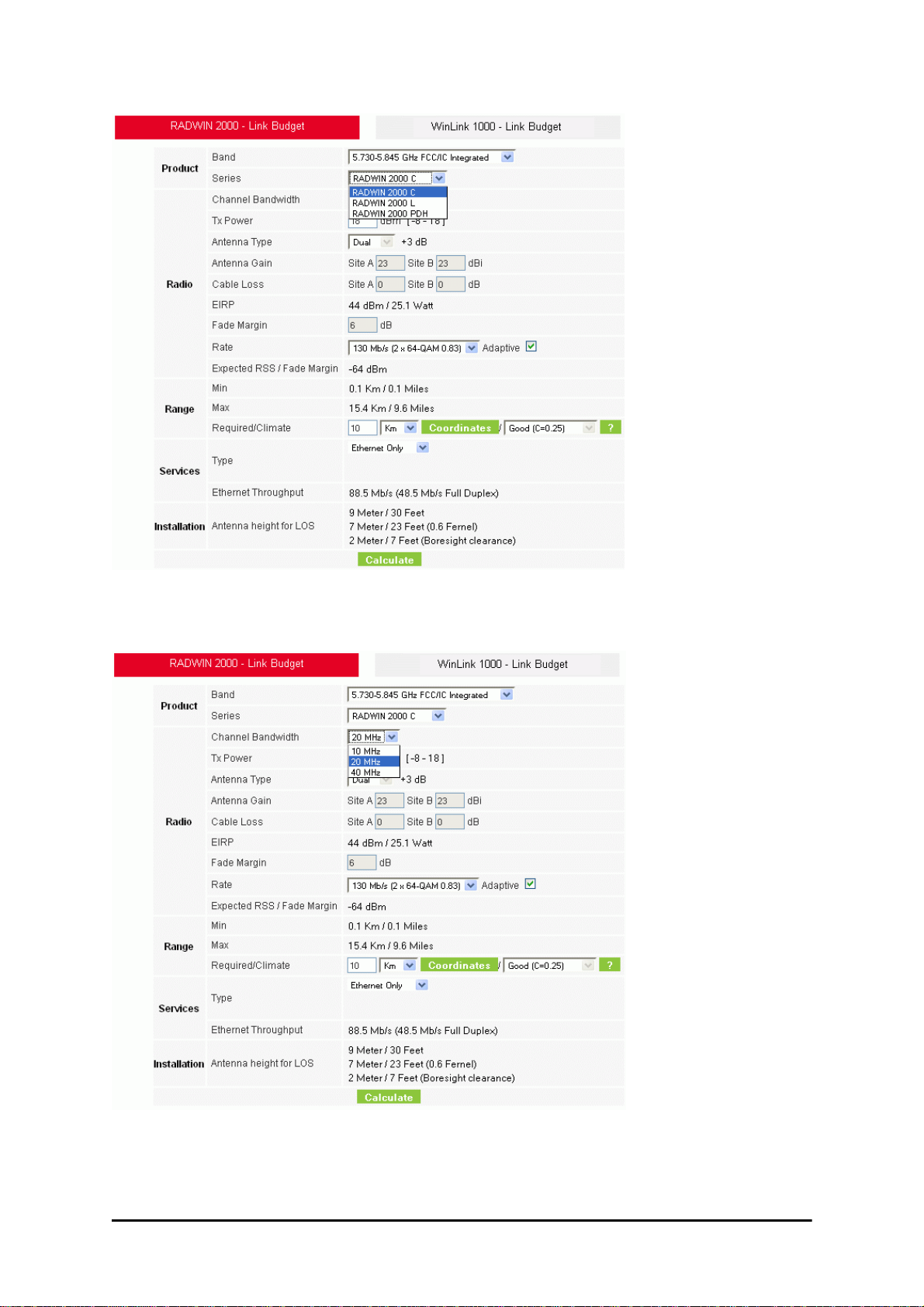
Running the Link Budget Calculator Chapter 21
Figure 21-5: RADWIN 2000 series selector
3. Choose the Channel Bandwidth.
Figure 21-6: RADWIN 2000 Channel Bandwidth selector
4. For a collocated link choose the RFP. Use the Help button to the right of the RFP
selection box for help:
RADWIN 2000 User Manual Release 2.5.40 21-7
Page 91
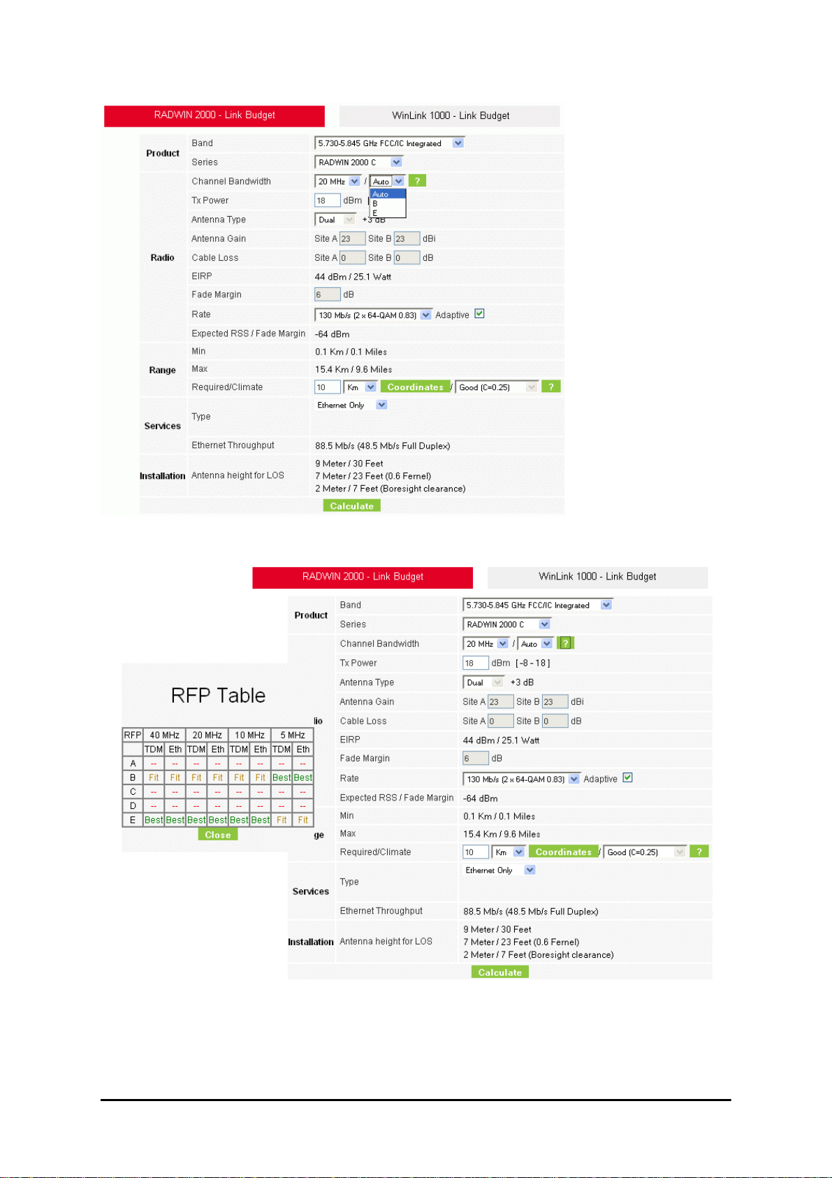
Running the Link Budget Calculator Chapter 21
Figure 21-7: RFP Selector
Figure 21-8: RFP Selection Guide
For collocated RADWIN 2000 products, you may only use RFP B or E.
5. Enter the radio details. Note that Rate is chosen from a drop-down list:
RADWIN 2000 User Manual Release 2.5.40 21-8
Page 92
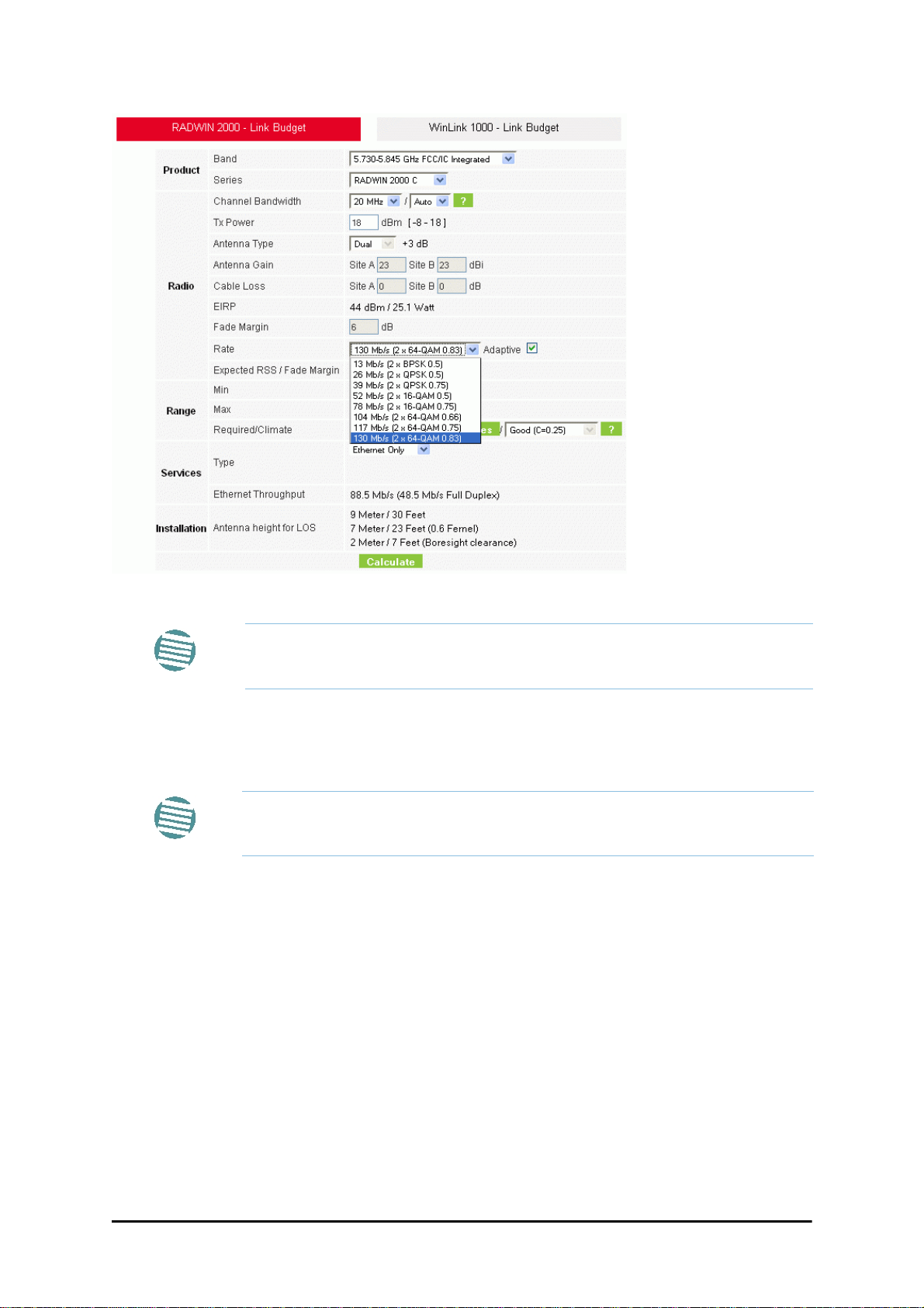
Running the Link Budget Calculator Chapter 21
Figure 21-9: Rate selector
If you choose Adaptive Rate, then the Rate list is unavailable as is the
Climate factor list. Both of these quantities are calculated.
Note
The Rate shown, defines the air-interface rate in Mbps. The system operates in TDD
mode and has the overhead of the air-interface protoco.l Thus, the Ethernet actual
throughput is provided by the Ethernet Rate.
For a given air-rate, Ethernet throughput will decrease with increasing range
due to propagation delay.
Note
The Fade margin is the minimum required for line-o- sight (LOS) conditions. For
degraded link conditions, a larger Fade margin should be used.
The EIRP is given in dBm and Watts.
6. If the required range between the two link sites is known, you may enter it directly.
Alternatively, you may enter the latitude and longitude of each site in the link, in
which case the distance between them will be calculated and displayed.
RADWIN 2000 User Manual Release 2.5.40 21-9
Page 93
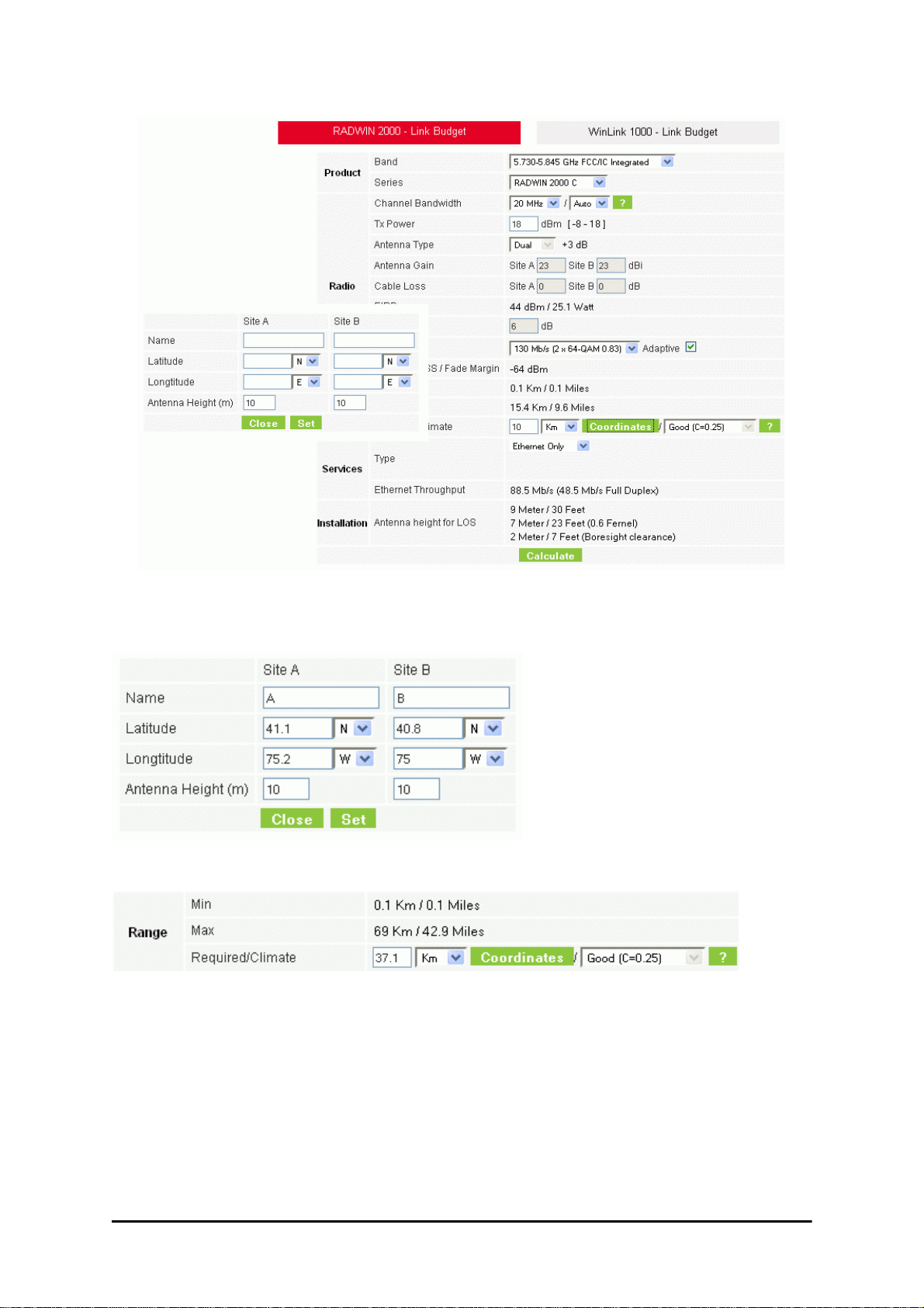
Running the Link Budget Calculator Chapter 21
Figure 21-10: Calculation of distance from site coordinates
For example, if you enter the following coordinates and press Set,
the range will be calculated and displayed:
If for example, we enter:
Site A: 41.1°N lat 74.2°W Long
Site B: 40.8°N lat 74.0°W Long
RADWIN 2000 User Manual Release 2.5.40 21-10
Page 94

Running the Link Budget Calculator Chapter 21
7. Click Set. The distance and link budget is calculated.
8. Located to the right of the green Coordinates button is a drop-down list of Climactic
C Factor values. It is only available if you choose a non-adaptive rate.
Figure 21-11: Climactic C Factors
For help about what these mean, click the ? button to the right of the list in
Figure 21-11.
RADWIN 2000 User Manual Release 2.5.40 21-11
Page 95
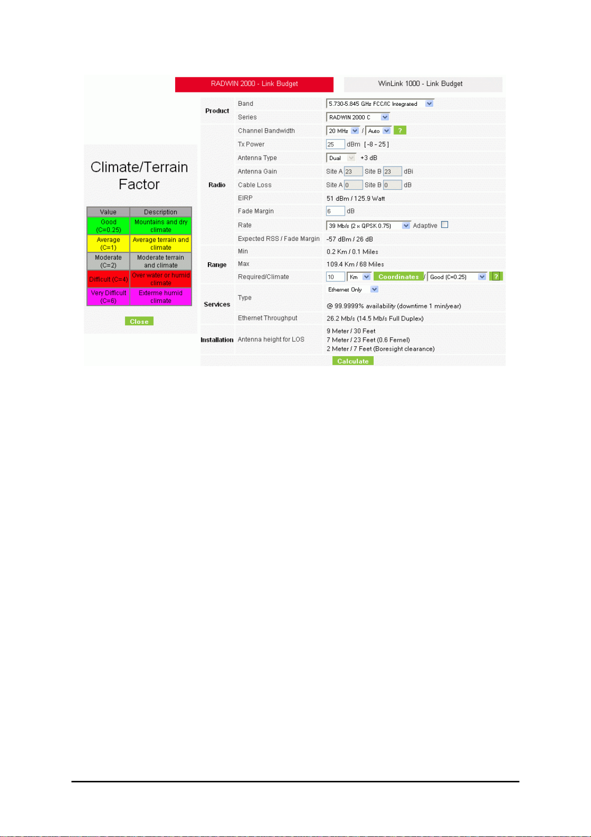
Running the Link Budget Calculator Chapter 21
Figure 21-12: Climactic C Factor description
In Figure 21-13 we display a map of the world showing C Factor contours:
Figure 21-13: World map showing C Factor contours
RADWIN 2000 User Manual Release 2.5.40 21-12
Page 96

Running the Link Budget Calculator Chapter 21
9. Click Calculate to obtain the required performance estimate.
Placing the cursor in any other calculated field will also update the
calculated results.
Note
Figure 21-14: LBC - Results section
The Expected Performance parameters are calculated and displayed:
• Expected RSS - the expected RSS that the RADWIN Manager shows when the RADWIN 2000 ODUs are optimally aligned
• Services Type - max number of T1 or E1 trunks if “Max Trunks” is selected
• Ethernet Rate - maximum throughput available for the chosen parameter combination
• Antenna height for LOS – the minimum antenna height required for line-of-sight
operation. It is the sum of the height required for boresight clearance due to the
earth’s curvature plus the height required to clear the Fresnel zone
If the expected performance is not suitable for your application, try diff erent par ameters and
repeat the calculation.
RADWIN 2000 User Manual Release 2.5.40 21-13
Page 97

Chapter 22
Quick Install Mode
Why this is Needed
It may be required to temporarily suspend service traffic over a link without losing the link
connection. The simplest way to do this is to place the link in Installation mode but without
changing any configured parameters. Quick Install Mode is a “one click” method for doing
this. The method is completely generic, working identically for both WinLink 1000 and RADWIN 2000 products.
Enabling Quick Install
By default, this feature is disabled.
To enable Quick Install mode:
1. Log on to the RADWIN Manager, navigate to Tools | Preferences and click the
Advanced tab:
RADWIN 2000 User Manual Release 2.5.40 22-1
Page 98

Using Quick Install Chapter 22
Figure 22-1: Preferences: Quick Install
2. Check the Enable Quick Install box and then OK. A new button is added to the
main window toolbar:
Figure 22-2: New Install Mode button for Quick Install mode
Quick Install mode may be disabled by unchecking the Enable Quick Install box.
Using Quick Install
To suspend service traffic and enter Installation mode:
1. Click the Install mode button. You are offered a confirmatory message:
RADWIN 2000 User Manual Release 2.5.40 22-2
Page 99

Using Quick Install Chapter 22
Figure 22-3: Change to Installation Mode cautionary message
2. Click Yes to continue. The link goes into Installation mode. The main window looks
the same as if you had entered Installation mode in the usual way through one of
the Site windows with the exception of the toolbar:
Figure 22-4: Service Mode button to resume link service traffic
3. When you are ready to resume normal service traffic, click the Service Mode button. The following cautionary message is displayed:
Figure 22-5: Resumption of services cautionary message
RADWIN 2000 User Manual Release 2.5.40 22-3
Page 100

Using Quick Install Chapter 22
4. Click Yes to continue. The link will resume normal services with your last set configuration parameters provides that you did not change link parameters in a a way
leading to sync loss.
It is also possible to change parameters in a way leading to service
degradation. For example mis-configuring the number of antennas or
transmission parameters at one side of the link may allow service to
resume, but in a degraded fashion.
Yo u may only enter Quick Install mode from a configured link. If you set
both sites back to factory settings and chose Quick Install, you will not be
able to continue:
Note
RADWIN 2000 User Manual Release 2.5.40 22-4
 Loading...