

Page 1
User Manual
Scales of Y/KTP series
Manual number:
ITKU-43-11-12-11-A
Control of Packaged Goods (CPG)
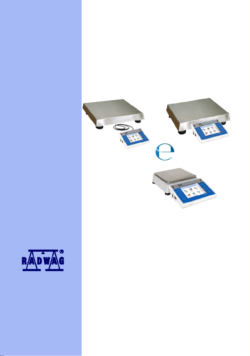
One stand version
• WLY/KTP Scales
• WPY/KTP Scales
MANUFACTURER OF ELECTRONIC
WEIGHING INSTRUMENTS
RADWAG Wagi Elektroniczne, 26–600 Radom, Bracka 28, POLAND
Phone +48 48 38 48 800, fax. +48 48 385 00 10
export@radwag.com
www.radwag.com
Page 2

DECEMBER 2011
2
Page 3

Table OF CONTENTS
1. NTENDED USE .............................................................................................................................................7 I
2. PRECAUTIONARY MEASURES....................................................................................................................7
3. WARRANTY CONDITIONS............................................................................................................................7
4. UNPACKING AND MOUNTING.....................................................................................................................8
4.1. cales of Y/KTP/C1 series........................................................................................................................8 S
4.2.
Scales of Y/KTP/D2 series........................................................................................................................9
5. SCALE STRUCTURE.....................................................................................................................................9
5.1. Main dimensions.......................................................................................................................................9
5.1.1. Scales of Y/KTP/C1 series...........................................................................................................9
5.1.2. Scales of Y/KTP/D2 series.........................................................................................................10
5.2. Descri tion of connectors .......................................................................................................................11p
5.2.1. Connectors’ description in PUE 7 ..............................................................................................11
5.2.2. Connectors’ description in PUE 7P ............................................................................................11
5.2.3. Description of glands PUE 7P....................................................................................................11
5.2.4. Connector with RS232 and I/O ..................................................................................................12
6. GETTING STARTED....................................................................................................................................12
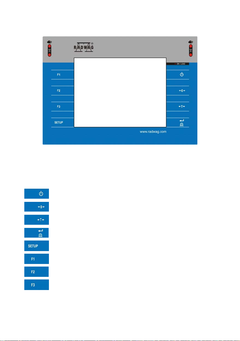
7. KEYPAD OVERLAY.....................................................................................................................................13
8. FUNCTIONS OF KEYS ................................................................................................................................13
9. PROGRAM STRUCTURE............................................................................................................................14
9.1. ain menu items ....................................................................................................................................14 M
9.2. Inventory of parameters..........................................................................................................................14
9.2.1. Scale parameters - weighing .....................................................................................................14
9.2.2. Working modes ..........................................................................................................................15
9.2.3. Communication..........................................................................................................................19
9.2.4. Devices ......................................................................................................................................20
9.2.5. Display .......................................................................................................................................22
9.2.6. Inputs / Outputs .........................................................................................................................23
9.2.7. Authorizations ............................................................................................................................24
9.2.8. Units ..........................................................................................................................................24
9.2.9. ther .........................................................................................................................................25O
9.2.10. ser Calibration.........................................................................................................................25 U
9.2.11. Info ............................................................................................................................................25
10. NDICATING WINDOW ..............................................................................................................................26 I
11. LOGGING IN..............................................................................................................................................27
11.1. n procedure............................................................................................................................27 Logging i
11.2. ut procedure..........................................................................................................................28 Logging o
1.3. Authorization access levels ..................................................................................................................281
12. NA IGATING WITHIN THE MENU ............................................................................................................29V
12.1. s .....................................................................................................................................................29 Key
2.2. Return to weighing................................................................................................................................301
13. WE HING.................................................................................................................................................31IG
13.1. s of operational use ...............................................................................................................31 Condition
13.2. .................................................................................................................................................32 Zeroing
13.3. ..................................................................................................................................................32 Tarring
13.4.
ng tare.......................................................................................................................................33 Inscribi
13.5.
eighing for dual range scales ............................................................................................................33 W
Toggling between weight units .............................................................................................................341
3.6.
14. SC LE PARAMETERS..............................................................................................................................34A
14.1. r..........................................................................................................................................35 Median filte
14.2. .....................................................................................................................................................35 Filter
14.3. zero...............................................................................................................................................36 Auto
14.4. eight for different functions (LO) .........................................................................................36 Minimum w
4.5. Last digit ...............................................................................................................................................371
15. CO MUNICATION.....................................................................................................................................37M
15.1. settings ....................................................................................................................................38 RS 232
15.2. etting...............................................................................................................................38 ETHERNET s
5.3. TCP protocol setting .............................................................................................................................391
16. DEVICES....................................................................................................................................................39
16.1. Computer..............................................................................................................................................39
16.1.1. Computer port............................................................................................................................39
3
Page 4

16.1.2. omputer address .....................................................................................................................40 C
16.1.3. ontinuous transmission............................................................................................................40 C
16.1.4. eighing printout template ........................................................................................................41 W
6.1.5. Cooperation with „E2R System”.................................................................................................411
16.2. Printer .................................................................................................................................................42..
16.2.1. rinter port.................................................................................................................................42 P
16.2.2. rinter code page ......................................................................................................................43 P
6.2.3. Templates for printouts ..............................................................................................................431
16.3. Barcode scanner ..................................................................................................................................45
16.3.1. ort for barcode scanner ...........................................................................................................45 P
16.3.2. refix / Suffix .............................................................................................................................45 P
16.3.3. ield selection............................................................................................................................46 F
6.3.4. Test ...........................................................................................................................................471
16.4. Transponder card reader ......................................................................................................................48
16.4.1. om port for transponder card readers......................................................................................48 C
6.4.2. Procedure of attributing the card number to an operator............................................................491
16.5. Additio al display..................................................................................................................................49n
16.5.1. dditional display port................................................................................................................49 A
16.5.2.
17. DISPLAY....................................................................................................................................................51
17.1. Text st ngs...........................................................................................................................................51ri
17.2. n keys .......................................................................................................................................54 Functio
17.3. ing platforms .............................................................................................................................54 Display
17.4. Bargraph type.......................................................................................................................................55
18. INPUTS / OUTPUTS...................................................................................................................................57
18.1. tion of inputs..........................................................................................................................58 Configura
8.2. Configuration of outputs .......................................................................................................................581
19. AU HORIZATION ......................................................................................................................................59T
19.1. mous Operator ...........................................................................................................................59 Anony
19.2. ate and time .......................................................................................................................................60 D
19.3. ts...............................................................................................................................................60 Printou
19.4.
9.5.
20.
UNI S.........................................................................................................................................................62T
20.1. t unit...............................................................................................................................................62 Star
20.2. efined units.................................................................................................................................63 User d
0.3. Acceleration of gravity ..........................................................................................................................632
21. OTHER PARAMETERS .............................................................................................................................64
21.1. s............................................................................................................................................64 Language
21.2. date and time............................................................................................................................64 Setting
21.3. .........................................................................................................................................65 Sound signal
21.4. or ..................................................................................................................................................65 Curs
1.5. Touch panel calibration ........................................................................................................................652
22. USER ADJUSTMENT ................................................................................................................................66
22.1. procedure..............................................................................................................................66 Adjusting
22.2. t mass adjustment..........................................................................................................................68 Star
22.3. from adjustment process...........................................................................................................68 Report
2.4. Adjustment track record ........................................................................................................................692
23. SPECIAL FUNCTIONS OF WORKING MODES ........................................................................................70
23.1. mode ...................................................................................................................................71 Recording
23.2. n-weighing.....................................................................................................................................71 Dow
23.3. eighing .....................................................................................................................................72 Checkw
23.4.
23.5.
Communication protocol frame ..................................................................................................50
17.1.1. isplay templates ......................................................................................................................52 D
17.1.2. creen font ................................................................................................................................53 S
17.1.3. ont size....................................................................................................................................53 F
7.1.4. Bold fonts...................................................................................................................................531
17.4.1. argraf “Quick weighing” ...........................................................................................................56 B
17.4.2. argraph “Signalling checkweighing ranges”.............................................................................56 B
17.4.3. Bargraph „Linear”.......................................................................................................................57
............................................................................................................................................61 Databases
Delete older data ..................................................................................................................................61 1
............................................................................................................................................72 Tare mode
Labelling mode .....................................................................................................................................73
23.5.1. Setting of the number of labels to print.......................................................................................73
4
Page 5

23.5.2. etting of the number of cumulative labels to print.....................................................................74 S
23.5.3. etting of the number of CC labels to print ................................................................................74 S
23.5.4. utomatic triggering of cumulative labels...................................................................................75 A
3.5.5. Automatic triggering cumulative labels of cumulative labels.......................................................762
3.6. Statistics ...............................................................................................................................................772
24. WORK MODE - WEIGHING .......................................................................................................................78
24.1. ting the working mode....................................................................................................................78 Star
4.2. Local setting of a working mode ...........................................................................................................792
25. WORKING MODES – COUNTING PIECES ...............................................................................................79
25.1. ting the working mode....................................................................................................................79 Star
25.2. Local settings of the workign mode.......................................................................................................80
25.2.1. utomatic correction of reference mass.....................................................................................80 A
5.2.2. Minimum reference mass...........................................................................................................812
25.3. reference unit by entering known piece mass........................................................................82 Setting a
25.4. reference unit by weighing a sample......................................................................................82 Setting a
25.5. the reference mass by entering single piece mass directly to the database..............................83 Setting
5.6. Inscribing the unit mass to the database...............................................................................................842
26. WORKING MODES – DEVIATIONS .......................................................................................................... 84
26.1. ting the operating mode .................................................................................................................84 Star
26.2.
settings of the workign mode.......................................................................................................85 Local
R
26.3. eference unit mass estimated by weighing.........................................................................................85
6.4. Rederence unit mass inscribing into the memory .................................................................................852
27. WORKING MODES – FORMULATION......................................................................................................86
27.1. ting the working mode....................................................................................................................86 Star
27.2. structure............................................................................................................................86 Formulation
27.3. setting of a working mode ...........................................................................................................87 Local
27.4. ption of functions and setting formulation (dosing) process ........................................................88 Descri
27.5. a new formulation (dosing process)........................................................................................90 Creating
27.6. Instan s of formulation and dosing processes....................................................................................91ce
27.6.1. nstance 1 – Manual formula making process of 4 ingredients on 2 weighing platforms ............91 I
27.6.2. nstance 2 – Automatic dosing of 2 ingredients on 2 weighing platforms ...................................94 I
7.6.3. Instance 3 – Mixed formula making process..............................................................................962
7.7. Reporting from completed formula making processes..........................................................................982
28. WORKING MODES – DENSITY.................................................................................................................99
28.1. ting the working mode....................................................................................................................99 Star
28.2. setting of a working mode .........................................................................................................100 Local
28.3. Carrying out density determination procedure .................................................................................... 101
28.3.1. etermining density of liquids ..................................................................................................101 D
28.3.2.
etermining density of solids ...................................................................................................102 D
etermining density of pycnometer..........................................................................................103 D
28.3.3.
8.3.4.
28.4. from completed density determination processes...............................................................107 Reporting
28.5. sity parameter for water ..................................................................................................108 Table of den
8.6. Table of density parameter for ethyl alcohol .......................................................................................1082
29. WORKING MODES – WEIGHING ANIMALS...........................................................................................109
29.1. ting the operating mode ...............................................................................................................109 Star
29.2. setting of a working mode .........................................................................................................109 Local
9.3. Carrying out animals weighing procedure...........................................................................................1102
30. WORKING MODES - CONTROL OF PACKAGED GOODS ....................................................................110
30.1. ting the working mode.................................................................................................................. 111 Star
30.2. setting of a working mode .........................................................................................................111 Local
30.3. start procedure.......................................................................................................................111 Control
30.4. ctive control with average tare...........................................................................................113 Non-destru
30.5. non-distructive testing in mode Empty-Full.......................................................................115 Performing
30.6. distructive testing in modes Empty-Full and Ful-Empty ....................................................116 Performing
30.7. estimating average tare ..................................................................................................117 Report from
0.8. Report from product testing ................................................................................................................1183
31. DA ABASES ...........................................................................................................................................121T
31.1. Search ng databases..........................................................................................................................121 i
Determining density of a porous body......................................................................................1052
uick name search..................................................................................................................122 Q
31.1.1.
31.1.2. uick code search................................................................................................................... 122
31.1.3.
Weighing date search ..............................................................................................................122
Q
5
Page 6

31.2. ew items in databases ..........................................................................................................123 Adding n
31.3. items in databases................................................................................................................123 Deleting
31.4. older data .............................................................................................................................124 Deleting
31.5. items from databases ............................................................................................................124 Printing
31.6. Export a database to a file..................................................................................................................125
31.6.1. xport the database of weighings............................................................................................125 E
31.6.2. xport the database of controls ...............................................................................................126 E
1.6.3. Eksport the database of average tares .................................................................................... 1273
31.7. Database edition ................................................................................................................................128
31.7.1. perators’ database ................................................................................................................128 O
31.7.2. atabase of products...............................................................................................................129 D
31.7.3. atabase of Weighings / Alibi ..................................................................................................130 D
31.7.4. atabase of clients ..................................................................................................................131 D
31.7.5. atabase of formulas...............................................................................................................132 D
31.7.6. atabase of reports from formulation....................................................................................... 133 D
31.7.7. atabase of density .................................................................................................................133 D
31.7.8. atabase of controls ................................................................................................................135 D
31.7.9. Database of average tares.......................................................................................................136
31.7.10. atabase of packages...........................................................................................................137 D
31.7.11.
atabase of warehouses....................................................................................................... 138 D
D
31.7.12. atabase of labels.................................................................................................................138
31.7.13. Database of universal variables.............................................................................................139
32. CO MUNICATION PROTOCOL..............................................................................................................139M
32.1. information ............................................................................................................................139 General
32.2. entory of RS commands ................................................................................................................140 Inv
32.3. message format...................................................................................................................140 Respond
32.4. scription ......................................................................................................................141 Command’s de
2.5. Manual printouts / automatic printouts ................................................................................................1483
33. COOPERATION WITH EXTERNAL DEVICES.........................................................................................149
34. DIAGRAMS OF CONNECTION CABLES ................................................................................................149
35. TECHNICAL PARAMETERS ...................................................................................................................151
35.1. s of WLY/KTP series..................................................................................................................151 Scale
5.2. Scales of WPY/KTP series .................................................................................................................1523
36. ERROR MESSAGES................................................................................................................................153
37. ADDITIONAL EQUIPMENT......................................................................................................................153
38. APPENDIX A – Variables for printouts..................................................................................................154
38.1. entory of variables .........................................................................................................................154 Inv
8.2. Formatting variables ...........................................................................................................................159 3
39.
APPENDIX B – Functions of programmable buttons ...........................................................................161
40. APPENDIX C – Label template...............................................................................................................165
40.1. a label from the terminal level ............................................................................................165 Designing
40.2. a label on a computer ........................................................................................................166 Designing
40.3. ing label templates in the scale.....................................................................................................170 Sav
40.4. ng a label to a product............................................................................................................170 Attributi
40.5. ng a label to a client................................................................................................................171 Attributi
0.6. Printing labels.....................................................................................................................................1714
41. APPENDIX D - CITIZEN printer setting ..................................................................................................171
42. APPENDIX E - ZEBRA printer setting....................................................................................................172
43. APPENDIX F - Communication with barcode scanners .......................................................................172
44. APPENDIX G – Computer Program „ViewerKTP”.................................................................................173
6
Page 7

1. INTENDED USE
The scales have implemented a module for testing prepackages. It uses
databases including products and operators. When the control is started
from the scale it is completed after testing the whole sample (number of
products resulting from the algorithm and depending on the batch quantity.
After the testing has been completed a report is generated. It includes all
the information required by regulations concerning testing prepackages.
It can be printed on a connected printer.
Testing cycle:
• choosing an operator,
• choosing a product,
• starting control,
• weighing subsequent products,
• completing the procedure after testing the number of products outlined
as a sample,
• printing the report.
2. PRECAUTIONA RY ME ASUR ES
A. Please, read carefully this user manual before and use the device
according to its intended use;
B. Weighed loads should be placed in possibly central part of scale pan;
C. Do not clean the device with agents causing corrosion;
D. Weighing pan should be loaded with goods having gross mass lower
than maximal capacity of the scale;
E. Do not leave loads on the pan for longer period of time ;
F. In case of failure, immediately disconnect scale power supply;
G. Devices that are to be withdrawn from usage should be utilized
according to the law.
3. WARRANTY CONDITIONS
A. RADWAG is obliged to repair or change those elements that appears
to be faulty because of production and construction reason,
7
Page 8

B. Defining defects of unclear origin and outlining methods of elimination
can be settled only in participation of a user and the manufacturer
representatives,
C. RADWAG does not take any responsibility connected with destructions
or losses derives from non-authorized or inappropriate (not adequate
to manuals) production or service procedures,
D. Warranty does not cover:
• Mechanical failures caused by inappropriate maintenance of
the device or failures of thermal or chemical origin or caused
by atmospheric discharge, overvoltage in mains or other
random event,
• Inappropriate cleaning.
E. Forfeiture of warranty appears after:
• Access by an unauthorized service,
• Intrusion into mechanical or electronic construction
of unauthorized people,
• Installing another operating system,
• Removing or destroying protection stickers.
F. The detailed warranty conditions one can find in warranty certificate.
G. Contact with the central authorized service:
+48 48 384 88 00 ext. 106 or 107.
4. UNPACKING AND MOUNTING
4.1. Scales of Y/KTP/C1 series
A. Take the device out of the package,
B. Put the scale on an even stiff ground,
C. Remove transport protection:
D. Scale should be levelled by turning regulation
feet. Levelling is correct if air bubble is situated
in the central position:
8
Page 9

4.2. Scales of Y/KTP/D2 series
A. Take the device out of the package,
B. Put the scale on an even stiff ground,
C. Fit the pan and the bracket under the device according to the drawing:
E. Scale should be levelled by turning regulation feet. Levelling is correct
if air bubble is situated in the central position:
5. SCALE STRUCT URE
5.1. Main dimensions
5.1.1. Scales of Y/KTP/C1 series
9
Page 10
Y/KTP/C1/R series – main dimensions
Y/KTP/C1/K series – main dimensions
5.1.2. Scales of Y/KTP/D2 series
10
Page 11
5.2. Description of connectors
5.2.1. Connectors’ description in PUE 7
1 – Ethernet RJ45
2 – RS232 (COM1)
1 – power supply socket
2 – I/O, RS232 (COM2)
3 – USB
5.2.2. Connectors’ description in PUE 7P
1 – Ethernet RJ45
2 – RS232 (COM1)
3 – USB
1 – I/O, RS232 (COM2)
5.2.3. Description of glands PUE 7P
1 – Supply cord gland
2 – Gland for platforms 1, 2
3 – Gland for platforms 3, 4
11
Page 12
5.2.4. Connector with RS232 and I/O
RS232 - DB9/M (male),
top view:
Pin2 - RxD
Pin3 - TxD
Pin5 - GND
I/O, RS232 DSUB15/F (female),
top view:
Pin1 - GNDWE
Pin2 - OUT1
Pin3 - OUT2
Pin4 - COMM
Pin5 - 6÷9VDC
Pin6 - IN4
Pin7 - IN3
Pin8 - TxD2
Pin9 - 5VDC
Pin10 - GNDRS
Pin11 - IN2
Pin12 - IN1
Pin13 - RxD2
Pin14 - OUT4
Pin15 - OUT3
6. GETTING STARTED
• After the terminal is connected to power the ON/LOAD
diode starts to light.
• Press
Windows CE together with RADWAG software loading is signalled
by blinking the red diode ON/LOAD.
• When the loading procedure is completed the main software
window appears.
to start the operating system loading procedure.
12
Page 13
7. KEYPAD OVERLAY
8. FUNCTIONS OF KEYS
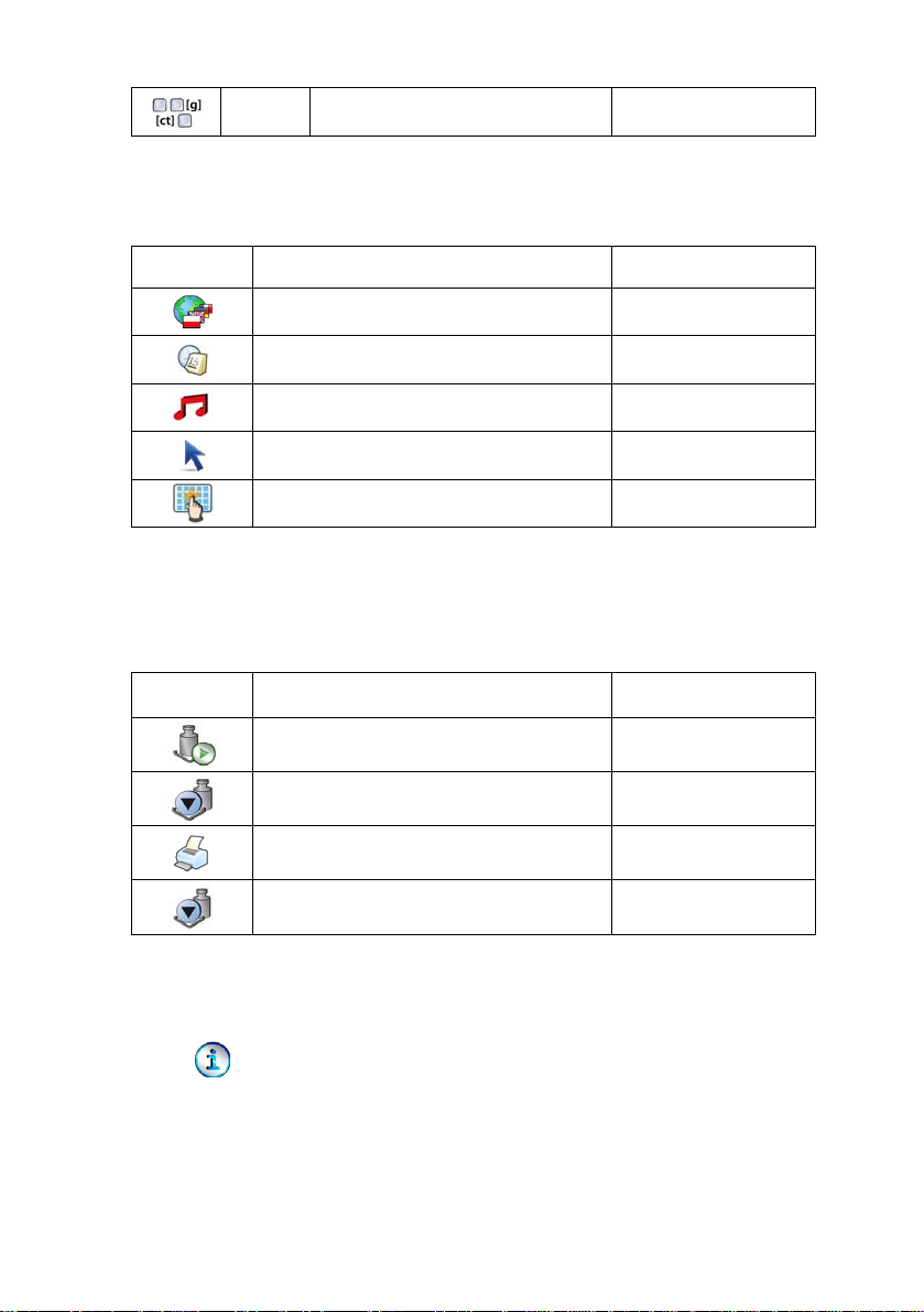
Key Description
Turning on/off the scale
Zeroing
Tarring
Printing out the result or confirming some entered data
Function key (entering the menu)
Selecting products
Selecting contractors
Inscribing a tare value
13
Page 14
9. PROGRAM STRUCTUR E
The main menu has been divided into twelve functional groups.
In every group there are parameters of similar use.
9.1. Main menu items
Icon Description
Scale
Databases
Working Modes
Communication
Devices
Display
Inputs / Outputs
Authorization
Units
Other
User Calibration
Info
9.2. Inventory of parameters
9.2.1. Scale parameters - weighing
Icon Description Value
Median Filter 0.5
Filter Fast
14
Page 15

Autozero Yes
LO threshold 0
Last digit Always
9.2.2. Working modes
Icon Description Value
Weighing -
Save Mode
Down-weighing No
Checkweighing No
Tare mode Single
Labelling mode -
Number of labels 1
No. of cumulative labels 1
No. of CC labels 1
C label automatic triggering -
Mode None
Manual, each
stable
Threshold 100
CC label automatic triggering -
Mode None
Threshold 100
Statistics Global
Counting pieces -
15
Page 16
Save Mode
Manual, each
stable
Down-weighing No
Checkweighing No
Tare mode Single
Labelling mode -
Number of labels 1
No. of cumulative labels 1
No. of CC labels 1
C label automatic triggering -
Mode None
Threshold 100
CC label automatic triggering -
Mode None
Threshold 100
Statistics Global
Automatic correction of reference mass No
Deviations -
Save Mode
Down-weighing No
Checkweighing No
Tare mode Single
Labelling mode -
16
Manual, each
stable
Page 17
Number of labels 1
No. of cumulative labels 1
No. of CC labels 1
C label automatic triggering -
Mode None
Threshold 100
CC label automatic triggering -
Mode None
Threshold 100
Statistics Global
Recipes -
Ask for multiplier No
Ask for number of cycles No
Confirm batching ingredients manually No
Global -
No. of weighings for calculating the
correction
0
Batching outputs -
Output 1 0
Output 2 0
Output 3 0
Output 4 0
Bulk batching output -
Output 1 0
17
Page 18

Output 2 0
Output 3 0
Output 4 0
Weighing animals -
Correction 0
Maximum correctional value 0
Checkweighing No
Tare mode Single
Labelling mode -
Number of labels 1
No. of cumulative labels 1
No. of CC labels 1
C label automatic triggering -
Mode None
Threshold 100
CC label automatic triggering -
Mode None
Threshold 100
Statistics Global
Averaging time 5
Automatic mode No
Density -
Standard liquid Water
18
Page 19
Temperature 21
Standard liquid density 1
Sinker volume 0
Ask abort sample number No
Pycnometer mass 0
Save Mode
Checkweighing No
Tare mode Single
Statistics Global
Control of packaged goods -
Save Mode
Statistics Global
Batch number -
Batch quantity 100
Estimating average tare No
Number of packages 10
9.2.3. Communication
Icon Description Value
Pycnometer density 0
Unit g/cm
Manual, each
stable
Manual, each
stable
3
COM1 -
Baud Rate 9600
19
Page 20
9.2.4. Devices
Icon Description Value
Data bits 8
Stop bits 1
Parity None
COM2 -
Baud Rate 9600
Data bits 8
Stop bits 1
Parity None
Ethernet -
DHCP No
IP Address 192.168.0.2
Subnet mask 255.255.255.0
Gateway 192.168.0.1
Tcp -
Port 4001
Computer
Port None
Address 1
Continuous transmission No
Weighing Printout Template -
20
Page 21
E2R System -
System is active No
Lock selecting products No
Printer -
Port COM1
Code page 1250
Printouts -
CPG report printout pattern
(Control of Packaed Goods)
Average tare report printout pattern
(Control of Packaed Goods)
Weighing printout template See ch. 16.2.3
Cumulative printout template See ch. 16.2.3
Cumulative printout template
for cumulative data
Adiustment report printout template See ch. 22.3
Recipe report printout template See ch. 27.7
Density printout template See ch. 28.4
Product printout template See ch. 16.2.3
Operator printout template See ch. 16.2.3
Client printout template See ch. 16.2.3
Warehouse printout template See ch. 16.2.3
Package printout template See ch. 16.2.3
Barcode reader -
Port None
Prefix 01
See ch. 30.8
See ch. 30.7
See ch. 16.2.3
21
Page 22
9.2.5. Display
Icon Description Value
Suffix 0d
Field selection See ch. 16.3.3
Test See ch. 16.3.3
Transponder card reader -
Port None
Additional display -
Port None
Template See ch. 16.5.2
Text information -
Displaying template See ch. 17.1.1
Font Courier
Font size Small
Bold Yes
Actions
F1 Button Choose product
F2 Button Choose client
F3 Button Set tare
Screen button 1 Local parameters
Screen button 2 Set MIN and MAX
Screen button 3 Statistics C: Print
Screen button 4 CCStatistics : Print
22
Page 23

9.2.6. Inputs / Outputs
Icon Description Value
Screen button 5 C Statistics : Zero
Screen button 6 Choose package
Screen button 7 Edit batch number
Screen button 8 None
Screen button 9 None
Left proximity sensor None
Right proximity sensor None
Set Default -
Show all platforms No
Bargraph type None
Inputs -
Input 1 None
Input 2 None
Input 3 None
Input 4 None
Outputs -
Output 1 None
Output 2 None
Output 3 None
Output 4 None
23
Page 24

9.2.7. Authorizations
Icon Description Value
9.2.8. Units
Icon Description Value
Anonymous operator Operator
Date & Time Administrator
Printouts Administrator
Databases
Products Administrator
Clients Administrator
Formulation Administrator
Packages Administrator
Warehouses Administrator
Labels Administrator
Delete older data Advanced Operator
Start unit None
Defined unit 1 -
Multiplier 0
Name -
Defined unit 1 -
Multiplier 0
Name -
24
Page 25
9.2.9. Other
Icon Description Value
Language Polish
Date & Time -
Beep Yes
Cursor No
Touch screen calibration -
9.2.10. User Calibration
Icon Description Value
Acceleration of gravity 9.80665
An option only for non-verified scale
Setting of start mass -
Calibration -
Report printout No
Adjustment track record -
9.2.11. Info
Submenu < Info> is for viewing information:
• Scale factory number,
• Program version,
• Scale program version.
25
Page 26

10. INDICATING WINDOW
Main view:
In the main application window one can see four separate parts:
• In the top part of the window there is a status bar where a work mode,
logged-in user, time&date are displayed and active connection with a
computer are displayed.
• Below the status bar you can see weighing window(s).:
• There is a workspace below this window:
26
Page 27
Notice:
The workspace is freely programmable. The default template is
described in ch. 17.1.1 of this manual.
• There are screen buttons below the workspace:
Notice:
1. Users can define screen function buttons. See the procedure
in ch. 17.2 of this manual;
2. The number of buttons to be defined depends on the selected
operating mode i.e.:
• In operating mode <Weighing> 9buttons are at ones disposal
displayed subsequently from 1 to 9 starting from the left side,
• In other working modes, part of the hot keys is permanently
assigned due to realized functions. Depending on selected
working mode, the user can use from 6 to 8 hot keys.
11. LOGGING IN
In order to have full access to user parameters and databases, the user
should log in as an <Administrator>.
11.1. Logging in procedure
• While in the main window press <log in> on the top of the screen
and the window with operators attributed to <
• After entering <
Admin> a screen keyboard runs with editing
Admin> will appear,
window for inscribing a password,
• Type password „1111” and confirm by pressing
,
• The program returns to the main window and in the title bar you will
see <Admin> instead of <log in>.
27
Page 28

11.2. Logging out procedure
• While in the main applilcation window press the name of a logged in
operator in the top bar on the screen to open the database of operators,
• Press logging out button situated in the top bar of the operators’
database window:
• The program returns to the main window and in the top bar the
operators name is substituted by <Log in>.
11.3. Authorization access levels
Weighing software uses four access levels: administrator, advanced
operator, operator, none. Every user with any attributed access level
can perform weighings and select data from in databases to be used
during weighing.
Access to user parameters, databases and working modes depending
on the authorization access level attributed:
Operator type Access level description
None
Operator
Advanced
Operator
Administrator
No access to user parameters. No weighing can be confirmed.
Cannot start procedure „Control of Packaged Goods”. Cannot
enter the reference mass unit and estimate the reference mase
unit by weiging in „Counting Pieces” and „Deviations”, density
determination and implementation of the recipe. No access to
<Export the weighing database to a file> in menu <Databases>
1)
Access to parameters in submenu: <Weighing>, <Display>
(excluding the group <Actions>), <Others>
1)
. Can start and
perform all weighing procedures. Access to <Export the
weighing database to a file> in menu <Databases>2).
Access to parameters in submenus: <Weighing>, <Working
modes>, <Communication>, <Devices>
<Others>
Access to <Export the weighing database to a file> in menu
<Databases>
1)
. Can start and perform all weighing procedures.
2)
.
Access to all user parameters, functions and databases
1)
, <Display>1),
2)
.
Can start and perform all weighing procedures.
2)
.
28
Page 29
1. Authorization level for editing functions:
• < Printouts> in submenu „ Devices / Printer”,
• <
• <
Sample> in submenu „ Devices /
Additional display”,
Displaying template> in submenu „ Display /
Text information”,
• <
Date and Time> in submenu < Others>,
It can be declared in submenu < Authorizations>, which is
accessable only for users with the <Administrator> authorization
level (see ch. 19 of this manual).
2. A user logged in as <Administrator> in submenu
Authorizations> (see ch. 19 of this manual) can change
<
authorization levels for accessing different databases and functions
Delete older data>. The exception are database
<
<
Weighings / Alibi>, that have the status „Read only”.
12. NAVIGATING WITHIN THE MENU
Owing to the colour display with the touch panel navigating within the menu
is simple and intuitive.
12.1. Keys
Entering the main menu
Menu list „up”
Menu list „down”
Scrolling „up-down”
29
Page 30
Enter (OK)
Abort
Add a new item in a database
Disabeling the formerly selected record e.g. logging out the
operator
Searching a database according to a date
Searching a database according to a name
Searching a database according to a code
Printing on item from a database
Exporting reports from testing and average tare
(for testing prepackages mode CPG)
Clearing an editing field
Screen keyboard on / off
Reading a printout template from a *.lb file
(active after connecting a pendrive)
Variables for a printout template
One level up
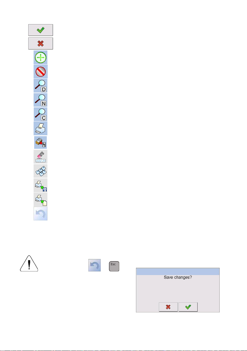
12.2. Return to weighing
The changes introduced are saved for good after they are
confirmed. Press
or
several times until the following
message box appears:
30
Page 31

Press: – to confirm changes or – to abort
changes. The program returns to weighing.
13. WEIGHING
Put a load on the weight pan. When pictogram is displayed the
indication is ready to read.
Notice:
A weighing can be saved after stabilising a measurement over zero
(pictogram
13.1. Conditions of operational use
In order to assure a long term operating period with appropriate
measurements following principles should be adhered to:
• Avoid applying mechanical shocks to the weight pan:
).
• Loads should be placed in the centre of the pan (eccentric errors
are outlined in PN-EN 45501 chapter 3.5 and 3.6.2):
• Do not apply concentrated forces (all load in one point):
31
Page 32

• Avoid side loads, particularly side strokes:
13.2. Zeroing
In order to zero the indication choose a platform on the touch panel and
press
following symbols usually appear:
Zeroing is possible only when the indication is stable.
Notice:
Zeroing is possible only within ±2% of full range around zero. If the
zeroed value is beyond the interval of ±2%, Err2 is displayed.
13.3. Tarring
In order to tare the scale choose a platform on the touch panel if necessary,
put a package on the pan and press
equal zero and following symbols usually appear: Net and
After placing a load on the weight pan net mass will be shown. Tarring is
possible within the whole range of the scale. After unloading the pan the
display shows the tarred value with minus sign.
. After zeroing is performed the indication is equal zero and
and .
. You will see the indication
.
32
Page 33

You can also inscribe tare values to the product database. Every product has
a field “Tare”. In that case tare is automatically set to this value after selecting
the product.
Notice:
Tarring cannot be performer when a negative or zero value is being
displayed. In such case Err3 appears on the display.
13.4. Inscribing tare
It is possible to inscribe a tare value.
Procedure:
• While in any work mode press
, then the screen keyboard
is displayed,
• Inscribe tare and press
,
• The program returns to weighing and the and the display shows
the entered value with the „–” sign provided there was zero before
on the display.
13.5. Weighing for dual range scales
Switching between the I range and the II range happens automatically
(exceeding Max of the I range).
Weighings in the second range is signalled by a pictogram in the top left
corner of the display
of the II range to the moment of returning to zero (autozero range
. Then weighings is done with the accuracy
)
where the scale switches back to the I range.
Switching between the II range and I range is automatic both in the
switching point the autozero zone.
33
Page 34

While in AUTOZERO – pictogram appears. Then pictogram
is off and a scale returns to weighing in the I range.
13.6. Toggling between weight units
Operators can change the weight unit in two ways:
• Pressing the unit symbol on the screen,
• Pressing formerly defined button <
Change unit>.
Possible selection:
• gram [g]
• kilogram [kg]
• carat [ct]
• pound [lb] *
• ounce [oz] *
• Newton [N] *
*) – weighing unit inaccessible in a verified scale
Notice:
1. The user can also declare the start unit and determine two custom
weighing units (user defined) – see point 20 of this user manual;
2. The procedure of attributing functions to buttons is described in ch.
17.2 of this manual.
14. SCALE PARAMETERS
Users can set the scale according to the ambient conditions (filtering level)
or own needs (autozero) and set the LO threshold for minimum load that
enables operation of some functions. This parameters are placed in
Weighing>.
<
In order to enter submenu < Weighing>, press and then:
„ Weighing”.
34
Page 35

Notice:
Weighing parameters are directly related to a specific weighing platform,
so at the beginning the weighing platform should be selected for which
we want to set parameters.
Inventory of scale parameters:
Median Filter
Filter
Autozero
LO Threshold
Last digit
14.1. Median filter
The median filter is intended for eliminating short-lasting mechanical shocks.
Procedure:
• Enter <
<
Weighing> according to ch. 14 of the manual, select
Median Filter> and then set an appropriate value.
Accessible settings:
None - median filter is off
0.5, 1, 1.5, 2, 2.5 - filtering level to choose
14.2. Filter
This filter is intended to suppress continuous mechanical vibrations at the
cost of stabilization time.
Procedure:
• Enter <
<
Weighing> according to ch. 14 of the manual, select
Filter> and then set an appropriate value.
35
Page 36

Accessible settings:
None, V.Fast, Fast, Average, Slow.
Notice:
The higher filtering level the longer stabilization time.
14.3. Autozero
The autozero function has been implemented in order to assure precise
indications. This function controls and corrects „0” indication.
While the function is active it compares the results continuously with
constant frequency. If two sequentional results differ less than the declared
value of autozero range, so the scale will be automatically zeroed and the
pictograms
and will be displayed.
If AUTOZERO is disabled zero is not corrected automatically. However,
in particular cases, this function can disrupt the measurement process e.g.
slow pouring of liquid or powder on the weighing pan. In this case, it is
advisable to disable the autozero function.
Procedure:
• Enter <
<
Weighing> according to ch. 14 of the manual, select
Autozero> and then set an appropriate value.
Accessible settings:
NO
YES
- Autozero off
- Autozero on
14.4. Minimum weight for different functions (LO)
Parameter <LO THRESHOLD> is associated with automatic weighing.
Next weighing will not be saved until the indication goes under the
THRESHOLD LO (net).
Procedure:
• After entering <
Threshold Lo> according to ch. 14 of this manual
a keyboard is displayed,
36
Page 37

• Inscribe LO and confirm by pressing .
14.5. Last digit
The last digit option < Last digit> is to switch off the last digit of
measured mass indication – the measurement is carried out with decreased
accuracy.
Procedure:
• Enter group of parameters <
this user manual, select parameter <
Weighing> in accordance with ch. 14 of
Last digit> and set its desired
value.
Accessible settings:
Always
Never
When stable
- Last digit always visible
- Last digit always switched off
- Last digit visible only on stable indication of mass
15. COMMUNICATION
The scale can communicate with external devices via different ports:
• COM 1 (RS232),
•
•
•
The communication can be configured in parameters’ group
Communication>.
<
In order to enter < Communication>, press and then:
„ Communication”.
COM 2 (RS232),
Ethernet,
Tcp.
37
Page 38

15.1. RS 232 settings Procedure:
• Enter < Communication> according to ch.15 of the manual, select
<
COM1> or < COM2>, and then set an appropriate value.
For RS 232 following parameters are accessible:
• Baud Rate - 4800, 9600, 19200, 38400, 57600, 115200 bit/s
• Data bits - 5, 6, 7, 8
• Stop Bit - No, 1, 1.5, 2
• Parity - No – Odd – Even – Mark – Space
15.2. ETHERNET setting Procedure:
• Enter < Communication> according to ch.15 of the manual,
select <
Ethernet> and then set an appropriate value.
Following settings are accessible for Ethernet:
• DHCP - Yes – No
• IP Address - 192.168.0.2
• Subnet Mask - 255.255.255.0
• Default gateway - 192.168.0.1
Notice:
The settings above are only for information purposes. Transmission
parameters should be matched to the local client network.
• After making changes press , then a new message is displayed:
<Restart to apply the changes>,
• Go back to weighing saving parameters and restart the device.
38
Page 39

15.3. TCP protocol setting
TCP (Transmission Control Protocol) is a protocol for communication
between two computers. It operates in mode client-server. Server awaits
on connection iniciation on a specified port while client initiates connection
to the server. Scale software allows setting the port for the „Tcp” protocol.
Procedure:
• Enter < Communication> parameter group as described
in chapter 16 of the manual,
• Select: „
Tcp / Port” then you will see window <Port>
with the screen keyboard,
• Enter the required number and press
.
16. DEVICES
16.1. Computer
The scale can cooperate with a computer. Active connection scale-computer
is signalled by icon
Computer> some settings needs to be configured for cooperation
<
with computers.
in the top bar of the main window. In submenu
Enter submenu < Computer>, press and then:
„ Devices / Computer”.
16.1.1. Computer port Procedure:
• Enter parameters’ group < Devices> according to ch.
16 of this manual,
• Select „
Computer / Port” and then set the appropriate option.
39
Page 40

The scale can communicate with a computer via following ports:
• RS 232 (COM1),
• RS 232 (COM2),
• Tcp.
16.1.2. Computer address Procedure:
• Enter < Devices> parameter group as described in chapter
16 of the manual,
• Choose „
Computer / Address” then the window <Address>
with the screen keyboard appears,
• Enter the required address and confirm it by pressing
.
16.1.3. Continuous transmission
Users can enable continuous transmission from the scale to a computer.
Setting parameter <
sending data from <
„Setup /
Devices / Computer / Weighing Printout
Continuous transmission> starts subsequent
Weighing Printout Template> set in submenu:
Template”.
Procedure:
• Enter parameters’ group < Devices> according to ch. 16 of this
manual,
• Choose „
Computer / Continuous transmission” and then
set an appropriate value.
Accessible settings:
No
Yes
- Continuous transmission off
- Continuous transmission on
40
Page 41

16.1.4. Weighing printout template
Users in parameter < Weighing Printout Template> can define
variables included in the printout from the scale to a computer.
Procedure:
• Enter < Devices> parameter group as described in chapter
16 of the manual,
• Choose „
Computer / Weighing Printout Template” then
the editing field <Weighing Printout Template> with the screen
keyboard appears,
• Modify the template if necessary and confirm the changes by pressing
.
Notice:
There are additional buttons in the bottom line of the screen keyboard.
They can be used while modifying a printout template.:
Screen keyboard on/off
Reading a printout template from a *.lb file (button active while
connecting a USB pendrive)
List of variables for printout templates (see the list in APPENDIX A
of this manual)
Clear the editing field
16.1.5. Cooperation with „E2R System”
Scales can cooperate with computer software „E2R System” that is
a modular system for complex production supervising by monitoring
of weighings processes. In order to allow the cooperation with
„E2R System” enable parameter <
Notice:
The parameter <
E2R System> can be activated by an authorized
service or the manufacturer.
E2R System>.
41
Page 42

Procedure:
• Enter < Devices> parameter group as described in chapter
16 of the manual,
• Choose „
Computer / E2R System / System is active”
and then set an appropriate value.
Accessible settings:
No
Yes
- System is not active
- System is active
• If during cooperation with <
is required for operators, go to parameter <
E2R System> product selection lock
Lock selecting
products> and set its value to <Yes>.
16.2. Printer
In < Printer> submenu users can:
• Setting communication with a printer,
• Setting code page of a printer,
• Setting templates of printouts.
To enter <
Printer>, press and then: „ Printer”
16.2.1. Printer port Procedure:
• Enter < Devices> parameter group as described in chapter 16
of the manual, choose „
appropriate option.
Printer / Port” and then select an
42
Page 43

Printers can be attached to:
• RS 232 (COM1),
• RS 232 (COM2),
• USB,
• Tcp.
16.2.2. Printer code page Procedure:
• Enter parameters < Devices> as described in chapter 16
of the manual,
• Choose „
Printer / Code Page” then the screen keyboard
will be displayed,
• Write the required code page and confirm by pressing
.
Notice:
The default value is 1250 – code page for Middle-East Europe.
16.2.3. Templates for printouts
Enter < Printouts> to define printout templates.
Procedure:
• Enter parameter group < Devices> as described in chapter
16 of the manual, then choose „
Printer / Printouts”,
• After editing a template a memo box with the default content and the
screen keyboard,
• Modify the template according to your requirements and confirm it by
pressing
Notice:
.
There are additional buttons in the bottom line of the screen keyboard.
They can be used while modifying a printout template.:
43
Page 44

Screen keyboard on/off
Reading a printout template from a *.lb file (button active while
connecting a USB pendrive)
List of variables for printout templates (see the list in APPENDIX A
of this manual)
Clear the editing field
Default printouts’ settings:
CPG report printout pattern
(Control of Packaed Goods)
Average tare report printout pattern
(Control of Packaed Goods)
Weighing Printout Template {0}
Cumulative Printout Template N={15} SUM={16}
Cumulative of Cumulative Printout
Template
Adiustment report printout template See ch. 22.3
Product Printout Template {50}
Operator Printout Template {75}
See ch. 30.8
See ch. 30.7
N2={20} SUM2={21}
{51}
{76}
Client Printout Template {85}
Warehouse Printout Template {130}
Package Printout Template {80}
Formulation report printout template See ch. 27.7
Density printout template See ch. 28.4
44
{86}
{131}
{81}
{82}
Page 45

16.3. Barcode scanner
The balance allows for cooperation with a barcode scanner. The scanner
can be used for quick search of:
• Products,
• Clients,
• Packages,
• Warehouses,
• Recipes,
• Universal variables,
• Batch number.
Configuration of communication can be configured in:
“
/ Devices / Barcode reader”.
Notice:
In submenu <
Communication> set the baud rate (default 9600b/sec).
The detailed description of cooperation scale – barcode scanner can be
found in APPENDIX F in this manual.
16.3.1. Port for barcode scanner Procedure:
• Enter < Devices> according to ch.16 of the manual, choose
„
Barcode reader / Port” and then set the appropriate value.
Barcode scanners can be connected to:
• RS 232 (COM1),
• RS 232 (COM2),
16.3.2. Prefix / Suffix
Users can edit a prefix < Prefix> or / and suffix < Suffix> in order to
adjust the program to accept transmission frames from the scanner.
45
Page 46

Notice:
A special protocol is required in order the code be received by RADWAG
equipment. It is required to program an appropriate prefix and suffix.
Prefix – one byte 01 hexadecimally, suffix one byte 0D hexadecimally.
The detailed description of cooperation scale – barcode scanner can
be found in APPENDIX F in this manual.
Procedure:
• Enter < Barcode Scanner> according to ch.16.3 of the manual,
• Chose parameter <
Prefix> and then enter, using the screen
keyboard, a required value (hexadecimal) and confirm it by pressing
.
• Chose parameter <
Suffix> and then enter, using the screen
keyboard, a required value (hexadecimal) and confirm it by pressing
.
16.3.3. Field selection
This option is connected with selecting data which the program will search
after reading a barcode.
Procedure:
• Enter < Devices> according to ch.16 of the manual,
• Chose „
the following list will be displayed:
Barcode Scanner / Field selection” and then
Product
Contractor
Package
Source warehouse
Target warehouse
Recipe
Universal variable
Batch number
46
Page 47

• Select an item and then you can edit following parameters:
Filtering
Offset
Code length
Declaring an item, according to which searching
is supposed to be performed (see the table below)
Setting the first significant character in code from
which the comparison with items is performed during
searching. All preceding characters are skipped
Setting the number of characters to be taken for
the search procedure counting form Offset
Start marker
End marker
Start marker declaration
End marker declaration
Inventory of items to be selected for filtering:
Record Item fo r filtering
Product None, Name, Code, EAN Code
Client None, Name, Code
Package None, Name, Code
Source warehouse None, Name, Code
Target warehouse None, Name, Code
Recipe None, Name, Code
Universal variable None, Code
Batch number No, Yes
16.3.4. Test
Operators, using parameter < Test>, can verify if a barcode connected
to the scale works properly.
Procedure:
• Enter submenu < Barcode Scanner> according to ch. 16.3 of this
manual,
47
Page 48

• After entering parameter < Test> window <Test> is opened with
an ASCII text box and HEX (hexadecimal) field,
• After scanning the code is entered to the ASCII field and HEX filed
and at the bottom of the window a test result is displayed.
When:
• <Prefix> and <Suffix> declared in settings are the same as
<Prefix> and <Suffix> in the read code then the test result is
<Positive>,
• <Prefix> and <Suffix> declared in settings are not the same as
<Prefix> and <Suffix> in the read code then the test result is
<Negative>.
16.4. Transponder card reader
Selecting operator (logging in) can be done in two ways:
• Typing a password on a keyboard,
• Approaching a transponder card to the reader.
The card needs to be registerd first.
Notice:
In case of problems with reading transponder cards check the submenu
Communication> and set appropriate baud rate (default 9600b/s).
<
16.4.1. Com port for transponder card readers Procedure:
• Enter group of parameters < Devices> according to ch. 16
of this manula, select „
Transponder cards reader / Port”
and set appropriate option.
48
Page 49

The scale can communicate with the reader via following ports:
• RS 232 (COM1),
• RS 232 (COM2).
16.4.2. Procedure of attributing the card number to an operator
To use a transponder card to log on an operator the card needs to be
ascribed to the operator in the database of operators.
Procedure:
• Connect the transponder card reader to the required communication
port (RS 232 COM1 or RS 232 COM2),
• Choose a communication port for the reader (see ch. 16.4.1 in this
manual),
• In submenu <
as in the reader (default 9600b/s),
Communication> set the baud rate to the same
• Enter the database of operators and edit the selected operator going
to the field <
• After entering the field <
field <Card Number> with the screen keyboard,
Card Number>,
Card Number> you will see the editing
• Having approached the card to the reader the program automatically
displays in editing field <Card Number> the number of read card,
• Confirm the number by pressing
and return to weighing.
16.5. Additional display
16.5.1. Additional display port Procedure:
• Enter parameters group < Devices> according to ch. 16
of this manual, select „
Additional display / Port”
and then choose an appropriate option from the list.
49
Page 50

Communication with additional displays can be performed via following
ports:
• RS 232 (COM1),
• RS 232 (COM2),
• Tcp.
16.5.2. Communication protocol frame
Y/KTP scale with following displays:
• WD display,
• WWG display.
To start cooperation of Y/KTP scale with displays go to parameter
Sample> and define an appropriate communication protocol.
<
Procedure:
• Enter parameters’ group < Devices> according to ch. 16 of this
manual,
• Choose „
<Sample> with the screen keyboard appears,
Additional display / Sample” then the editing field
• Inscribe the required frame template using the screen keyboard or
choose the it from the list after pressing
.
Specified templates for displays:
{141}
{142}
- Protocol template for WD displays
- Protocol template for WWG display
• Confirm the changes by pressing
.
Notice:
In default settings parameter <
Sample> has ascribed {141}
(WD display).
50
Page 51

17. DISPLAY
Users can adapt the main display and visible information to their needs.
All parameters of the display can be found in the parameters’ group
Display>.
<
Entering <
• Direct pressing in the work area of the main display,
Display> can be made in two ways:
• Pressing and then: „ Display”.
Inventory of parameters of the main display:
Text information
Buton functions
Show all platforms
Bargraph Type
17.1. Text strings
In < Text information> users can set:
Display template
Screen font
Font size
Bold font
51
Page 52

17.1.1. Display templates
The main application window comprises a work area including information
that can be freely configured by a user.
Procedure:
• Enter < Display> according to ch. 17 of this manual,
• Choose: „
Text information / Displaying template”, then an
editing field with prompted value is displayed together with the screen
keyboard,
• Modify the template if necessary and confirm the changes by pressing
.
Notice:
There are additional buttons in the bottom line of the screen keyboard.
They can be used while modifying a display template. :
Screen keyboard on/off
Reading a display template from a *.lb file (button active while
connecting a USB pendrive). *.lb files with the default templates
of display in every language version are accessible on the CD
attached to the device
List of variables for display templates (see the list in APPENDIX A
of this manual)
Clear the editing field
Default display template:
{40:Product:,-15}{50}
{40:Tare:,-15}{9}{11}
{40:Gross:,-15}{8}{11}
{40:Number:,-15}{15}
{40:Total:,-15}{16}{11}
52
Page 53

17.1.2. Screen font
The font type can be changed in the display workspace.
Procedure:
• Enter < Display> according to ch. 17 of this manual,
• Choose: „
Text information / Font” and set the required font
type.
Accessible fonts:
• Arial,
• Courier.
17.1.3. Font size
Setting the font size for the workspace in the display.
Procedure:
• Enter < Display> according to ch. 17 of this manual,
• Choose: „
Text information / Font size and set the required
font size.
Accessible sizes:
• small,
• Average,
• Large.
17.1.4. Bold fonts
Setting bold fonts in an area of the workspace of the display.
Procedure:
• Enter < Display> according to ch. 17 of this manual,
53
Page 54

• Choose: „ Text information / Bold” and choose a setting.
Accessible settings:
NO
YES
- Bold is off
- Bold is on
17.2. Function keys
In submenu < Actions> users can set actions following keys:
function keys,
screen keys,
proximity sensors.
If a button has been attributed a function it has been activated at the same
time. If a button or sensor has no ascribed a function in stays inactive.
Procedure:
• Enter < Display> according to ch. 17 of this manual,
• Choose <
Buton functions> and choose a required setting for
a choosen button: F1, F2, F3, 9 screen buttons or proximity sensors.
Notice:
The list of functions that can be attributed to keys or buttons is listed
in APPENDIX B of this manual.
17.3. Displaying platforms
If a scale is equipped with two platforms users can switch between platforms
in three ways:
• By pressing the platform number on the scale screen,
54
Page 55

• By pressing a formerly defined button < Change platform>.
• By activating in parameters all platforms that will be separately
placed in the main window of the program. In that case platforms
can be activated by pressing the area of this platform.
Notice:
The procedure of attributing functions to buttons is described in ch. 17.2
of this manual.
To activate all platforms press , choose:
„ Parameters / Display / Show all platforms”, and set
appropriately.
- Displaying all platforms disabled
NO
YES
- Displaying all platforms enabled
17.4. Bargraph type
A bargraph is a typical visualisation procedure. It helps in quick weighing.
It requires less concentration to read if a weighing is between minimum
and maximum thresholds.
To see the bargraph on the screen enable it in parameters.
Procedure:
• Enter < Display> according to ch. 17 of this manual,
• Choose <
Bargraph type> and set the required bargraph type.
Accessible bargraphs:
• Quick weighing,
• None (Bargraph is not displayed),
• Signalling checkweighing ranges,
• Linear.
55
Page 56

17.4.1. Bargraf “Quick weighing”
• The bargraph consists of 8 red fields and three green fields.
• The green fields signal weighings between MIN and MAX
threshold, where:
MIN = the minimum threshold of acceptable weighing - LO
MAX = the maximum threshold of acceptable weighing - HI
• If a measurement is over the MIN (to the value of 1/3 of MIN-MAX) the
green field with a triangle on the left is visible. If the measurement is
between 1/3 and 2/3 of MIN-MAX the rectangular green field is visible.
If the measurement is between 2/3 of MIN-MAX and MAX a green field
with a triangle on the right is visible.
• If the mass value is below the MIN threshold red fields with red arrows
on the left are visible. The lower mass value the more red arrows are
visible.
• If the mass value is over the MAX threshold red fields with red arrows
on the right are visible. The higher mass value the more red arrows
are visible.
Thresholds MIN and MAX are on the borders between red and green fields.
17.4.2. Bargraph “Signalling checkweighing ranges”
• This type of bargraph comprises one green and 2 red fields.
• The left red field – signals that the load on the pan is lower than
the minimum weighing threshold (Min threshold);
56
Page 57

• The central green field – signals that the load on the pan is within the
set required interval for the weighed product (OK value between Min
and Max thresholds);
• The right red field – signals that the load on the pan is greater than
the maximum weighing threshold (Max threshold).
17.4.3. Bargraph „Linear”
The bar graph represents in a linear way the measuring range of a scale.
In addition, the bar graph can indicate weighing thresholds MIN, MAX, if they
have been determined:
• Signalization of mass below the value set in MIN threshold:
• Signalization of mass within MIN and MAX values of thresholds:
• Signalization of mass exceeding the value set in MAX threshold:
18. INPUTS / OUTPUTS
WLY scales are equipped with 4 inputs / 4 outputs. To adjust software
to the users needs configure inputs outputs in the submenu
in the submenu <
Inputs / Outputs>:
• indicator inputs,
•
indicator outputs.
57
Page 58

In order to enter submenu < Inputs / Outputs>, press
and then
: „ Inputs / Outputs”.
18.1. Configuration of inputs Procedure:
• Enter < Inputs / Outputs> according to ch. 18 of this manual,
• Choose < Inputs> and enter the selected input you will see
a list of functions to ascribe,
• Choose the required function from the list and return to weighing
saving the changes according to ch. 12.2 of this manual.
Notice:
The list of functions to ascribe to inputs are described in APPENDIX B
of this manual. By default inputs have no ascribed functions <None>.
18.2. Configuration of outputs
Ascribing a function to the output enables the output at the same time.
If an output has no ascribed function it is disabled.
Procedure:
• Enter < Inputs / Outputs> according to ch. 18 of this manual,
• Choose < Outputs> and enter the required output, then you
will see the list of functions:
None
Stabile
MIN stable
MIN non-stable
OK stable
Output disabled
Stable weighing result over LO threshold value
Stable weighing result below the MIN threshold
Non-stable weighing result below the MIN threshold
Stable weighing result between MIN and MAX thresholds
58
Page 59

OK non-stable
MAX stable
Non-stable weighing result between MIN and MAX
thresholds
Stable weighing result over the MAX threshold
MAX non-stable
Confirmation of
cycle completion *
Non-stable weighing result over the MAX threshold
Signal that confirms that a cycle of dosing has been
completed (the defined amount)
*) Not applicable to „Standard” software.
• Choose the required function from the list and return to weighing saving
the changes according to ch. 12.2 of this manual.
Notice:
By default all outputs have no function attributed – setting <None>.
19. AUTHORIZATION
The submenu < Authorization> is accessible only while being logged
in as the Administrator. In this group of parameters access levels can be
outlined.
To enter submenu < Authorization>, press and then:
„ Authorization”.
19.1. Anonymous Operator
The program allows to attribute the authorization access level to an operator
who does not perform the log-in procedure (anonymous operator).
Procedure:
• Enter < Authorization> according to ch. 19 of this manual,
choose <
Anonymous Operator>, and then set the
authorization access level.
59
Page 60

Accessible authorization levels:
None, Operator, Advanced Operator, Administrator.
19.2. Date and time
Default settings allow a logged-in Administrator to change settings of date
and time. Software however allows to change the access level to this option:
Date and time>.
<
Procedure:
• Enter parameters’ group < Authorization> according to ch.
19 of the manual, choose <
Date and time>, and then set
the parameter.
Accessible authorization levels:
None, Operator, Advanced Operator, Administrator.
Notice:
Setting <None> allows free access to settings of date and time
(without the need of logging in).
19.3. Printouts
Default settings of the scale allows a logged on Administrator to edit
printout templates. Software allows to change the access level to option
Printouts>.
<
Procedure:
• Enter parameter group < Authorization> according to ch. 19
of this manual, choose <
Printouts>, and set appropreately.
Access levels to printouts that can be set:
None, Operator, Advances Operator, Administrator.
60
Page 61

Notice:
When you choose setting <None> printout templates can be changed
even without logging on.
19.4. Databases
It is possible to set the access levels to the following databases:
• Database of Products,
• Database of Clients,
• Database of Formulas,
• Database of Packages,
• Database of Warehouses,
• Database of Labels.
Procedure:
• Enter parameters’ group <
of the manual, choose <
Authorization> according to ch. 19
Databases>, and then set the parameter.
Accessible authorization levels:
None, Operator, Advanced Operator, Administrator.
Notice:
Setting <None> allows free access to settings of date and time
(without the need of logging in).
19.5. Delete older data
Default settings allow a logged-in Advanced Operator delete older data
from the <
to change the access level to this option: <
Weighings / Alibi> database. Software however allows
Delete older data>.
Procedure:
• Enter parameters’ group <
of the manual, choose: „
Authorization> according to ch. 19
Databases / Delete older data”,
and then set the parameter.
61
Page 62

Accessible authorization levels:
None, Operator, Advanced Operator, Administrator.
20. UNITS
Scale, in submenu < Units> enables selecting:
• Declaring the start unit,
• Determining two user defined units (custom units),
• Changing the value of g-cor (the value of gravitational acceleration
force).
To enter submenu <
Units>, press and then: „ Units”.
20.1. Start unit Procedure:
• Enter submenu < Units> in accordance with ch. 20 of this user
manual,
• Select option <
Start units> and choose a start unit from displayed
list of available weighing units.
Possible selection:
• none
• gram [g]
• kilogram [kg]
• carat [ct]
• pound [lb] *
• ounce [oz] *
• Newton [N] *
*) – weighing unit inaccessible in a verified scale
• Exit to main manu with procedure of saving changes,
• On restarting the scale, the instrument operates with enabled start unit.
62
Page 63

20.2. User defined units Procedure:
• Enter submenu < Units> in accordance with ch. 20 of this user
manual,
• Select option <
Defined unit 1> and determine the values of the
following parameters:
Multiplier
Name
Multiplier of scale’s adjustment unit
Unit name (Max 3 characters)
• Exit to main manu with procedure of saving changes,
• Press symbol of the new weighing unit visible in the weighing window,
which activates list of available weighing units with new custom unit
added at the end of the list.
Notice:
The procedure of defining the second custom unit <
Defined unit 2>
is equal to the procedure described above.
20.3. Acceleration of gravity
Parameter < Acceleration of gravity> eliminates the changes of
gravitational acceleration force at different latitudes and altitudes in case
of weighing process with application of “Newton” [N] weighing unit.
Procedure:
• Enter submenu < Units> in accordance with ch. 20 of this user
manual,
• Select option <
window < Acceleration of gravity> with a numeric keyboard,
Acceleration of gravity> which opens an editing
• Insert the new value of acceleration of gravity for the place of use and
accept it by pressing
key,
• Exit to main manu with procedure of saving changes.
63
Page 64

21. OTHER PARAMETERS
There is a group of parameters different from others which influence the
operation of the scale. They are gathered in group <
language, beep etc. To enter <
„
Others”.
Others>, press and then:
Others> e.g.
21.1. Languages Procedure:
• Enter submenu < Others> according to ch. 21 of this manual,
choose <
Language> and set the parameter.
Accessible languages:
• Polish, English, German, French, Russian, Spanish, Czech, Hungarian,
Estonian, Latvian, Italian, Greek, Turkish.
21.2. Setting date and time
Users can set date and time that are visible in the main window of the
display. Entering the edition of date and time can be made in two ways:
• Pressing the field „date and time” in the top bar of the main screen,
• Pressing button and then: „ Others / Date and Time”.
After entering the setting of date and time the screen keyboard appears.
Set year, month, day, hour, minutes and confirm by pressing
.
Notice:
Parameter <
Date and Time> is accessible in the scale menu depending
on the authorization access level set in the related parameter.
64
Page 65

21.3. Sound signal Procedure:
• Enter < Others> according to ch. 21 of this manual, < Beep>
and set accordingly.
Settings:
None
Buttons
Sensors
All
- Sound for buttons and proximity sensors disabled
- Sound for buttons enabled
- Sound for proximity sensors enabled
- Sound for buttons and proximity sensors enabled
21.4. Cursor In order to start working with a computer mouse enable parameter <Cursor>. Procedure:
• Enter < Others> according to ch. 21 of this manual, choose
parameter <
Settings:
No
Yes
Cursor> and set an option.
- Cursor disabled
- Cursor enabled
21.5. Touch panel calibration
Touch panel calibration is required when inappropriate operation is
recognized. E.g. the reaction in a different place than the touching point.
Procedure:
• Enter submenu < Others> according to ch. 21 of this manual,
• Select <
Touch Screen Calibration> and then an editing field
appears,
• Using a thin and soft pointer press (keep pressed for some time)
in the point where the cross appears, after indicating the 4
confirm changes by pressing ENTER/PRINT.
th
place
65
Page 66

22. USER ADJUSTMENT
An option only for non-verified scale
Scales require to recalculate internal divisions to more suitable ones (e.g.
g, kg etc.). In order to do this they require an adjustment factor. It is adjusted
during the adjustment procedure using a mass standard. Adjustment should
be carried out if weighing a standard mass shows a different mass value.
To enter < User Adjustment>, press key and then:
„ User Adjustment”.
22.1. Adjusting procedure
• Enter submenu <
and select: “
User Adjustment > according to ch. 22
Adjustment”,
• After entering the parameter the following message box appears:
• Take the load off the pan of platform 1,
• Press button . The following message appears during
adjusting start mass: „Evaluation of starting mass”,
• After the procedure has been completed the following message
box appears:
66
Page 67

• Place determined mass on pan of platform 1 and then select ,
• After the procedure of adjustment factor determination following
command appears:
• Return to weighing, saving parameters.
Setting of start mass> parameter allows to adjust
<
start mass of platform 1.
Notice:
The factory calibration process for platforms 2, 3, 4 is analogical to the one
described above.
Return to weighing:
The changes introduced are saved for good after they are confirmed.
Press
several times until the following message box appears:
Press:
– to confirm changes or – to abort
changes. The program returns to weighing.
67
Page 68

22.2. Start mass adjustment
It is possible to adjust only a start mass, it helps to correct the start zero
when the span does not change.
Procedure:
• Enter submenu < User Adjustment > according to ch. 22
and select: “
Setting of start mass”,
• After entering the parameter the following message box appears:
• Take the load off the pan of platform 1,
• Press button
start mass: „Evaluation of starting mass”,
. The following message appears during adjusting
• After the procedure has been completed the following message
box appears:
• Return to weighing, saving parameters.
22.3. Report from adjustment process
Parameter < Report printout> enables activating the function of
automatic printout of a report from adjustment process on a printer plugged
to the scale.
68
Page 69

Procedure:
• Enter submenu < User Adjustment> in accordance with ch. 22 of this
user manual, select parameter <
Report printout> and set its
appropriate value.
Where:
No
Yes
- Automatic report printout switched off
- Automatic report printout switched on
Notice:
Submenu: “
/
Adjustment report Printout template” enables optional modification
Devices / Printer / Printouts
of report template (see ch. 16.2.3 of this user manual).
22.4. Adjustment track record
Each completed adjustment process is automatically saved in scale’s
database in submenu <
Adjustment track record>.
In order to enter submenu < Adjustment track record >, press
key, and
: „ User Adjustment / Adjustment track record”. Files
comprising reports have names with time and date when the process was
performed.
List of data for a carried out adjustment process:
Date
Operator
Nominal Mass
Platform number
Data of carried out operation
Operator name
Mass of adjustment weight
Platform number on which an operation was performed
The user can print data on a specific entry by pressing
in the upper bar of software’s window.
69
key, located
Page 70

23. SPECIAL FUNCTIONS OF WORKING MODES
WLY scales can operate in following work modes:
Weighing
Counting pieces
Deviations
Recipes
Weighing animals
Density
Control of packaged goods
Work modes can be configured in < Working Modes>.
To enter submenu <
Working Modes>, press and then:
„ Working Modes”.
The settings of specific working modes provide access to special functions
adjusting operation of the instruments to client’s individual needs. Part of the
special functions have global effect, i.e. they are applicable to most of
accessible working modes, as presented on below table:
Weighing
Save Mode + + + - - + +
Down-weighing + + + - - - -
Checkweighing + + + - + + -
Tare mode + + + - + + -
Labelling mode + + + - + - -
Statistics + + + - + + +
Counting
pieces
Deviations Recipes
Weighing
animals
Density KTP
Other special funcions are related directly to a specific working mode,
and they are described in further part of this user manual.
70
Page 71

Notice:
1. First left screen button
every working mode is ascribed to access settings of current mode.
(local settings) in the main window of
2. The change in on mode results in the same change for other working
modes working modes.
23.1. Recording mode
Depending on setting parameter < Save Mode> users can send data
from the scale to an external device.
Procedure:
• Enter parameters group < Working modes> according
to ch. 23 of this manual,
• Enter the required mode and choose <
Save Mode> then choose
the required mode.
Accessible options:
• Manual every stable,
• Manual first stable,
• Automatic first stable,
• Automatic last stable.
23.2. Down-weighing
Software allows to weigh in the “down-weighing” mode. It consist in putting
the load on the pan and taking off/removing portions of it with concurrent
saving weighings equal to the portions taken off the pan.
Procedure:
• Enter parameters group < Working Modes> according
to ch. 23 of this manual,
• Enter the required working mode and choose <
and then set the required option.
71
Down-weighing>
Page 72

Accessible options:
No
Yes
- Traditional weighing
- Down-weighing mode
23.3. Checkweighing
In case of enabling the checkweighing mode, printouts are performed only
when a weighing is between MIN and MAX thresholds that have been
defined before.
Procedure:
• Enter parameters group < Working Modes> according to ch. 23
of this manual,
• Enter the required working mode and choose <
Checkweighing>
then set the required option.
Options:
No
Yes
- Every weighing is recorded
- Only weighings between MIN, MAX are recorded.
23.4. Tare mode
This function enables users to set parameters for tarring.
Procedure:
• Enter parameters group < Working Modes> according to ch. 23
of this manual,
• Enter the required working mode and choose <
Tare mode>
and then set the required option.
Options:
Single
- Basic tare mode. The set (chooden) tare value is
overwritten after entering a new value
72
Page 73

Current sum
- Summing up tare values of product and package
together with manually inscribed tare. After next setting
of product or package tare the entered tare value is
disabled
Total sum
Autotare
- Summing up all subsequently entered tare values
- Automatic tare mode together with mode <Sum of all>
23.5. Labelling mode
Labelling mode can be initiated together with every working mode. The
labelling system is intended to print labels for marking weighed goods e.g. a
packing process. The program can print standard labels for single products,
cumulative labels for sticking to bulk containers and cumulative labels for
cumulative labels for sticking to the large transport containers holding bulk
containers.
In submenu < Labelling mode> there are accessible following special
functions:
Number of labels
No. of cumulative labels
No. of CC labels
C label automatic triggering
CC label automatic triggering
23.5.1. Setting of the number of labels to print
In the parameter < Number of labels> user defines the amount
of labels. They are printed on the printer connected to the weight.
Procedure:
• Enter parameters group <
Working Modes> according
to ch. 23 of this manual,
73
Page 74

• Enter the required working mode and choose: „ Labelling mode /
Number of labels” then the editing field <Number of labels>
with the screen keyboard is opened,
• Choose the required number of labels and confirm by pressing
23.5.2. Setting of the number of cumulative labels to print
In the parameter < No. of cumulative labels> define the amount
of sum labels. They are printed on connected printer.
Procedure:
.
• Enter parameters group <
Working Modes> according to ch. 23
of this manual,
• Enter the required working mode and choose: „
Labelling mode /
No. of cumulative labels”, then the editing field
<No. of cumulative labels> with the screen keyboard is opened,
• Enter the required number od cumularive labels and confirm by
pressing
.
23.5.3. Setting of the number of CC labels to print
In the parameter < No. of CC labels> define the amount of total sum
labels to print. They are printed on connected printer.
Procedure:
• Enter parameters group <
Working Modes> according to ch. 23
of this manual,
• Enter the required working mode and choose: „
Labelling mode /
No. of CC labels”, then the editing field <No. of CC labels>
with the screen keyboard is opened,
• Enter the required number od cumularive labels and confirm
by pressing
.
74
Page 75

23.5.4. Automatic triggering of cumulative labels
Users have access to the function of automatic triggering of printing
cumulative labels after setting parameters <
<
Threshold>.
Mode> and
Procedure:
• Enter < Working modes> parameter group as described
in chapter 23 of the manual,
• Enter the required working mode and choose: „
C label automatic triggering / Mode” and then set the
Labelling mode /
required option:
None
- Cumulative label printout is initiated by pressing
*
or
Mass
- Cumulative label printout is initiated by exceeding the
value set in parameter <
is treated as the total from single weighings,
- Cumulative label printout is initiated by exceeding the
Number
value set in parameter <
is treated as the number of single weighings.
*) Manual printing of cumulative labels can be done in two ways
depending on the button used:
Printing followed by zeroing label counter or the total mass
Printing without zeroing label counter or the total mass
,
Threshold>. The value
Threshold>. The value
By default setting button is accessible in the bottom part of the
display but activating the button
Parameters / Display / Actions”
can be done in subm„enu:
(see ch. 17.2 of the manual).
75
Page 76

For automatic printout of cumulative labels counters and total mass
variables are always zeroed.
• Confirm the changes by pressing
<
Threshold> then <Threshold> window appears with the screen
keyboard,
and go to parameter
• Set the appropriate value for automatic triggering cumulative labels:
− If parameter < Mode> is set to <Mass> then enter the required
value of total mass to exceed in order to print the C label,
− If parameter < Mode> is set to <Number> use the screen
keyboard to enter the required counter value as a threshold to
• Confirm the changes introduced by pressing .
23.5.5. Automatic triggering cumulative labels of cumulative labels
Users have access to the function of automatic triggering of printing
cumulative labels of cumulative labels after setting parameters
<
Procedure:
• Enter < Working modes> parameter group as described
trigger off printing C labels.
Mode> and < Threshold>.
in chapter 23 of the manual,
• Enter the required working mode and choose: „
CC label automatic triggering / Mode” and then set the
required option:
None
- Cumulative label of cumulative labels printout is initiated
*
Mass
by pressing
- Cumulative label of cumulative labels printout is initiated by
exceeding the value set in parameter <
The value is treated as the total from single weighings,
or
,
76
Labelling mode /
Threshold>.
Page 77

Number
- Cumulative label of cumulative labels printout is initiated by
exceeding the value set in parameter <
The value is treated as the number of single weighings,
Threshold>.
*) Manual printing of cumulative labels can be done in two ways depending
on the button used:
Printing followed by zeroing label counter or the total mass
Printing without zeroing label counter or the total mass
By default setting button is accessible in the bottom part of the
display but activating the button
Parameters / Display / Actions” (see ch. 17.2).
can be done in subm„enu:
For automatic printout cumulative labels of cumulative (CC)
labels counters and total mass variables are always zeroed.
• Confirm the changes by pressing and go to parameter
<
Threshold> then <Threshold> window appears with
the screen keyboard,
• Set the appropriate value for automatic triggering CC labels:
− If parameter < Mode> is set to <Mass> then enter the required
value of total mass to exceed in order to print the CC label,
− If parameter < Mode> is set to <Number> use the screen
keyboard to enter the required counter value as a threshold to
• Confirm the changes introduced by pressing .
23.6. Statistics
All statistics are continuously updated after each measurement is saved
in the scale memory. Statistics can be calculated globally (does not depend
on the selected product) or separately for every product from the product
database. It can be set in parameters <
trigger off printing CC labels.
77
Statistics>.
Page 78

Procedure:
• Enter < Working modes> parameter group as described
in chapter 23 of the manual,
• Enter the required working mode and choose <
Statistics>
and then set the required option.
Options:
Global
Product
- global statistics,
- statistics for every product.
Notice:
In case of operation with <
Statistics> set to <Product> bare in mind
that after restarting only statisics of the last weighed product are recovered.
24. WORK MODE - WEIGHING
The < Weighing> mode is the standard working mode allowing
to perform weighings and saving them in the database
<
Weighings / Alibi>.
24.1. Starting the working mode
The < Weighing> mode is the standard working mode. If a user
has changed the operating mode to another follow the actions below:
• While in the main window press the icon with mode name placed on
the top bar on the left then submenu comprising all accessible working
modes <Working Modes> opens,
• Choose <
window displaying icon
Weighing>, program automatically returns to the main
in the top bar.
78
Page 79

24.2. Local setting of a working mode
Local setting of a working mode < Weighing> are accessible on pressing
a hot key <
Local parameters>:
Save Mode
Down-weighing
Checkweighing
Tare mode
Labelling mode
Statistics
Detailed description in ch. 23.1 of the user manual
Detailed description in ch. 23.2 of the user manual
Detailed description in ch. 23.3 of the user manual
Detailed description in ch. 23.4 of the user manual
Detailed description in ch. 23.5 of the user manual
Detailed description in ch. 23.6 of the user manual
25. WORKING MODES – COUNTING PIECES
Counting pieces is work mode allowing to count pieces on the basis of the
standard unit mass of a single piece set on the scale or fetched from the
database.
Notice:
If counting pieces is performed in an additional container it should be tarred.
25.1. Starting the working mode Procedure:
• While in the main window press
in the top bar, then you will
see a submenu <Working Modes> comprising a list of modes,
• Choose <
to the main window displaying icon
Counting Pieces>, program automatically returns
in the top bar,
• The weight unit is automatically changed to „pcs” and two screen
buttons on the right side appear:
79
Page 80

Enter piece mass
Estimate piece mass
25.2. Local settings of the workign mode
Local settings of the working mode < Counting Pieces> are accessible
on pressing a hot key <
Local parameters>:
Save Mode
Down-weighing
Checkweighing
Tare mode
Labelling mode
Statistics
Automatic correction of reference mass
Minimum reference mass
Detailed description in ch. 23.1
of the user manual
Detailed description in ch. 23.2
of the user manual
Detailed description in ch. 23.3
of the user manual
Detailed description in ch. 23.4
of the user manual
Detailed description in ch. 23.5
of the user manual
Detailed description in ch. 23.6
of the user manual
Detailed description in ch. 25.2.1
of the user manual
Detailed description in ch. 25.2.2
of the user manual
25.2.1. Automatic correction of reference mass
It concerns the
Counting pieces> working mode
<
Working mode < Counting Pieces> comprises a special function
<
Automatic correction of reference mass>, that can be used for
correcting the unit mass <SMP>.
To enable the function in parameters you need to:
80
Page 81

• Enter parameter group < Working modes> according to ch.
23 of this manual, choose: „
Counting Pieces / Automatic
correction of reference mass” and set appropriate option.
Options:
- Automatic correction of reference mass disabled
No
- Automatic correction of reference mass enabled
Yes
Function <
Counting Pieces> is enabled at the moment of estimating the sample
<
Automatic correction of reference mass> in mode
quantity and signalled by displaying <PCS> and <SMP> (single piece mass)
on the top part of the display.
There are four criteris of working “Automatic correction of reference
mass”
function:
1. equilibrium should be reached,
2. quantity of pieces should be increased,
3. added quantity of pieces should not be greater than double
number of pieces on the pan,
4. the new sample can be different from the old sample by ± 0.3
of pcs (absolute value),
If a user recognises that the sample quantity is adequate the unit mass
(single piece mass) can be saved (see ch. 24.5 of this manual)
and disable the function by pressing ENTER/PRINT.
Notice:
While the function is active ENTER/PRINT changes its functionality.
Pressing ENTER/PRINT does not result in printing and saving weighings.
25.2.2. Minimum reference mass
It concerns the
Counting pieces> working mode
<
Users before beginning the procedure of single piese mass evaluation can
declare “minimum reference mass” i.e. minimum total weight of all pieces
put on the scale pan expressed in reading divisions.
81
Page 82

Procedure:
• Enter parameter group <
Working modes> according to ch.
23 of this manual,
• Choose „
Counting pieces / Minimum reference mass”
and then set an appropriate value.
Accessible settings: 1 d, 2 d, 5 d, 10 d.
Notice:
While the procedure of evaluation the mass of single piece the the mass
of all pieces put on the pan is lower than the value declared in parameter
Minimum reference mass”, the following warning message will
„
be displayed: < Too low sample mass>.
25.3. Setting a reference unit by entering known piece mass Procedure:
• Enter mode <
Counting Pieces> according to ch. 25.1
of this manual,
• Press
(enter piece mass), then an editing field is displayed
<Reference Unit> with the screen keyboard,
• Enter a value and confirm it by pressing
Counting Pieces> with automatic setting the reference unit.
<
, which causes starting
Notice:
1. In case of entering a reference unit higher then the maximum weighing
range of the main scale the program will display a message box:
<Value too high>,
2. In case of entering the single piece mass lower than 0.1 d, the
program will display a message box: <Value to small>.
25.4. Setting a reference unit by weighing a sample Procedure:
• Enter mode <
Counting Pieces> according to ch. 25.1
of this manual,
82
Page 83

• If pieces are weighed in a container it needs to be put on the pan
and tarred,
• Press
<Reference Quantity> together with the screen keyboard,
(estimate piece mass), then the editing field is displayed
• Enter a value and confirm it by pressing , then the following
message is displayed: <Put pieces: xx> (where xx – the value
entered before),
• Put the declared quantity of pieces on the pan and when the result
is stable (symbol
) confirm it by pressing .
• The program automatically calculates reference unit mass and
causes starting <
Notice:
Counting Pieces>.
• The total mass of all pieces put on the weight pan cannot be greater
than the weighing range;
• The total mass of all pieves put on the weight pan cannot be less than
the value declared in parameter „Minimum reference mass” (see
section 22.8). If the condition above is not fulfilled the scale dispalays
the message <Too low sample mass>;
• The mass of one unit may not be less than 0.1 of reading division
of the scale. If this condition is not fulfilled the scale dispalays the
message: <Too low piece mass>.
25.5. Setting the reference mass by entering single piece mass directly to the database
After selecting a product from the product database a mass of single
piece from the field <Mass> is used.
Procedure:
• While in <
• Using
Counting Pieces> press ,
or choose a product and confirm it by pressing .
Notice:
The selected product has to have declared unit mass (single piece m ass).
83
Page 84

25.6. Inscribing the unit mass to the database
The unit mass can be described a unit mass the following way:
a) Estimate the unit mass (see 25.2 and 25.3),
b) Enter the products database
,
c) Keep the finger pressed on the required position then a context
menu is displayed,
d) Choose option <Ascribe standard>, then the standard unit mass
is attributed to the product in the field <Mass>.
Notice:
Attributing a standard to a selected product is also possible by
programmable button. Setting programmable buttons is described in ch.
17.2 of this manual The list of functions is described in APPENDIX B
of this manual.
26. WORKING MODES – DEVIATIONS
The program allows to check weighings in deviations (in %) around an
outlined standard mass. The standard mass can be outlined by weighing
or entering it by a user.
26.1. Starting the operating mode
Procedure:
• While in the main window press
you will see a submenu <Working Modes> comprising a list of modes,
• Choose mode <
Deviations>, the program will automatically
in the top bar of the window then
returns to the main window displaying icon
in the top bar,
• The weight unit is automatically changed to „%” and two screen
buttons on the right side appear:
Enter reference mass
Estimate reference mass
84
Page 85

26.2. Local settings of the workign mode
Local settings of the working mode < Deviations> are accessible on
pressing a hot key <
Local parameters>:
Save Mode
Down-weighing
Checkweighing
Tare mode
Labelling mode
Statistics
Detailed description in ch. 23.1 of the user
manual
Detailed description in ch. 23.2 of the user
manual
Detailed description in ch. 23.3 of the user
manual
Detailed description in ch. 23.4 of the user
manual
Detailed description in ch. 23.5 of the user
manual
Detailed description in ch. 23.6 of the user
manual
26.3. Reference unit mass estimated by weighing
Procedure:
• Enter < Deviations> according to ch. 26.1 of this manual,
• If the standard is to be weighed in a container, the container needs
to be put on the pan and tarred,
• Press
<Put standard>,
(Estimate standard mass), then a message is displayed:
• Put the load on the pan. After stabilization the result is taken as
a standard (symbol
). Confirm it by pressing ,
• At the same time the weight unit is changed to (w %).
26.4. Rederence unit mass inscribing into the memory
Procedure:
• Enter < Deviations> according to ch. 26.1 of this manual,
85
Page 86

• Press (Give piece mass), then an editing field is displayed
<Give piece mass> together with the screen keyboard,
• Enter a value and confirm by pressing
,
• At the same time the weight unit is changed to (w %).
27. WORKING MODES – FORMULATION
< Formulation> is a working mode designed for creating formulas of
products on a scale series WLY. The working mode enables manual and
automatic dosing on a single or simultaneously on many weighing platforms.
27.1. Starting the working mode
Procedure:
• While in main window of the software, press on-screen key, located
in the upper bar of the window, which opens submenu < Working
Modes> containing list of available working modes,
• Select working mode <
returns to displaying the main window, and the upper bar indicates the
Formulation>, the software automatically
icon of selected working mode
,
• Simultaneously, two hot keys are activated on the right side of bottom
tool bar:
Start formulation process
Stop formulation process
27.2. Formulation structure
All activities related to formulation process can be carried out from the level
of scales WLY. Each formulation <
> contains:
• Its name < >,
• formulation code <
>,
86
Page 87

• assigned weighing platforms < > defined on a terminal.
Each of the weighing platforms can have its specific formulation or dosing
process (maximal number of processes for a single formulation is 2, as this
is the maximal number of weighing platforms connectable to a single
WLY scales).
Formulas database has the same searching mechanisms for a specific
formulation (record in a database) as other terminal databases.
A formulation can be searched in a database by:
• formulation name < >
• formulation code <
>
Processes carried out on different weighing platforms operated by the same
terminal, can also be dependant on each other, e.g.: dosing on weighing
platform 2 can be initiated only on completing dosing on weighing platform 1,
which is confirmed by a signal from appropriate sensor.
27.3. Local setting of a working mode
Local settings for the working mode < Formulation> are accessible
on pressing a hot key <
Ask for multiplier
Ask for number of cycles
Global
Confirm batching
ingredients manually
No. of weighings for
calculating the correction
Batching outputs
Bulk batching output
Local parameters>:
Causes setting a question for formulation
multiplier, i.e. the number which is used to
multiply the values of mass of all formulation
components.
Causes setting a question on number of
formulation cycles, i.e. number of repetitions
of the same formulation.
Causes enabling manual confirmation by
pressing “Enter/Print” key on terminal’s
keyboard for each weighing process.
Determines the number of recent
measurements which are analyzed for
calculating automatic correction in dosing
Global settings of doisng process
Enables setting the outputs for dosing (fine
dosing in case of two-step dosing process)
Enables setting outputs for bulk dosing in
case of two-step dosing process
87
Page 88

Correction
Maximum correctional
value
Enables determining global value of
correction for all weighing platforms
Enables detemining maximal value of
correction, which can be automatically
determined for all weighing platforms
Global> settings are dedicated for the process of creating simple
<
formulas, e.g.: dosing a single ingredient on all weighing platforms.
27.4. Description of functions and setting formulation (dosing) process
While creating formulation (dosing) process, the user has acces sto the
following functions:
Icon
Short
[DH]
[DA]
Function Description
cut
Dose manually
Mass
Min
Max
Product
Down-weighing
Automatic batching
Mass
Mass for fast dosing
Product
Down-weighing
Function recalling manual weighing of
formulation ingredient (manual dosing)
Mass of an ingredient to be dosed
MIN threshold for formulation ingredient
MAX threshold for formulation ingredient
Formulation ingredient uploaded from
Products database
Enables switching on checkweiging mode
(weighing on minus)
Function enabling automatic weighing
(automatic dosing). The function enables
controlling outputs dedicated for dosing
process.
Mass of an ingredient to be dosed
Mass of an ingredient for bulk dosing
(in case of two-step dosing process)
Formulation ingredient uploaded from
Products database
Enables switching on checkweiging mode
(weighing on minus)
88
Page 89

[O]
[TI]
[ST]
[CM]
[CI]
[EM]
Outputs
Delay
Time
Description
[Z]
Zero
[T]
Tare
Set Tare
Weight condition
Threshold
Mass
Weight condition
Input condition
Give mass
Function enabling setting the status of
terminal’s outputs for controlling peripheral
devices plugged to those outputs. Accessible
settings: None – output disabled; “0” – output
with low status; “1” – output with high status.
Function determining interval between carrying
out the following formulation steps. The
function determines pending time for the
following step counted in seconds.
Determination of pending time counted in
seconds
Text description of an interval displayed on
terminal’s touch panel
Zeroing the weighing platform, equal to
operation of the Æ0Å function key on the
terminal’s front panel
Tarring the weighing platform, equal to
operation of the ÆTÅ function key on the
terminal’s front panel
Tare setting function, equal to operation of the
<Set tare> function key on the terminal’s front
panel
Weight condition function determining time in
which the following step of dosing process ona
weighing platform should be carried out, e.g.:
the following step is carried out if mass (net or
gross) placed on the weighing platform is below
the value set in threshold.
Value of mass set in threshold for the condition
Kind of determined mass for threshold (net or
gross)
Weight condition – “>=” or “<”
Conditional function, determining when the
followwing step should be carried out,
depending on status of terminal’s intput. Each
input can take the following status: None –
input disabled; „0” – input with low status; „1” –
input with high status; „/” – input with increasing
tendency (status change from low to high, e.g.:
the moment of pressing a key); „\” – input with
decreasing tendency (status change from high
to low, e.g.: the moment of releasing a key)
Function activating a so called: “mass in hand”
– ingredient’s mass of a formulation supplied in
ready packages with precisely determined
mass. The given mass is added to weighed
ingredient’s mass, e.g.: ingredient to be
weighed = 21,8 kg, weighed amount 1,8 kg
placed on the scale, and 20 kg inserted
manually.
89
Page 90

Give number
[ET]
[CF]
[F]
of batching
repetitions
Set flags
Flags condition
Function determining quantity of batches of
weighed ingredient, that is added to a
formulation. Mass of a single batch is
determined in a product selected from the
database (Products database – field Mass).
Product’s mass is multiplied by a specific value,
and such determined mass is added to
weighing process. The function is applicable for
weighing products in batches.
Function determining a condition (characteristic
point) in formulation or dosing process. The
funtion enables conditional carrying out another
step in formulation process. Setting the
characteristic point (signal flags) in connection
with condition flags enables mutual conditioning
different processes on different weighing
platforms.
Conditional function determining criteria for
events, which have to occur in order to carry
out the following step in formulation (dosing)
process.
27.5. Creating a new formulation (dosing process)
Creating a new formulation is initiated by specifying its name and code,
followed by determining processes on each of the weighing platforms.
Procedure:
• Press key and select option < Databases> from main
menu Æ then select <
Formulation>,
• In order to create a formulation, press < Add> key, and confirm
creating a new record in formulation database,
• Specify formulation’s name < > and code < > by pressing
corresponding hot keys, and inserting a name and a code using an
on-screen keyboard,
• Select weighing platform on which the formulation (dosing) process
is created, e.g.: <
Platform 1>.
90
Page 91

• Arrange the steps of formula making process for weighing platform
1 by pressing <
Add> key, and one of accessible functions
designed for formulation processa (see table in ch. 27.4 of this
user manual). Each of the steps is added one by one.
• There is a possibility of modifying an already designed process –
adding or deleting a single step in a process, e.g.: in order to add
an element in a process, press and hold for 4 seconds an element
before which a new step should be added. Drop-down menu with
available options is displayed
Edit
Add
Delete
Cancel
• Press “Add” and define new element of the process.
27.6. Instances of formulation and dosing processes
27.6.1. Instance 1 – Manual formula making process of 4 ingredients on 2 weighing platforms
Description:
A formulation contains 4 ingredients, which are weighed on two weighing
platforms:
• Weighing Platform 1: ingredients: Flour and Sugar
• Weighing Platform 2: ingredients: Seasoning and Water
Formulation process includes a condition, according to which before adding
an ingredient “Water”, all other ingredients have to be dosed. The condition
is marked with signal flags, which determine formula making process
between the weighing platforms, in a way which orders dosing Water
ingredient as the last one. The whole process is described below in
tables, separately for each weighing platform.
Formulation name: Instance 1
Formulation code: 1111
91
Page 92

Formula making process controlled from the terminal:
Platform 1:
Icon Step Value Description
1. [TI] Delay
2. [CI] Input condition Input 1 – „/”
3. [T] Tare Tare
4. [DH] Dose
manually
5. [TI] Delay
6. [CI] Input condition Input 4 – „/”
7. [Z] Zero Zero
8. [TI] Delay
9. [CI] Input condition Input 1 – „/”
10. [T] Tare Tare
11. [DH] Dose
manually
12. [TI] Delay
13. [CI] Input
condition
14. [Z] Zero Zero
15. [F] Set flags
16. [O] Outputs
[5s] Place
empty
container
1 kg [Flour]
[5s] Unload
container with
product
[5s] Place
empty
container
0,2 kg [Sugar]
[5s] Unload
container with
product
Input 4 – „/”
Set signal flag
1
Output 1 –
„1”
Pending for loading an empty container
for the first product
Input 1 has to take increasing tendency –
press function key confirming loading a
container
Tarring the weighing platform no. 1
Manual weighing product “Flour” to obtain
1 kg mass
Pending for unloading the container with
weighed product from the weighing
platform
Input 4 has to take increasing tendency –
press function key confirming unloading a
container from the weighing platform
Zeroing the weighing platform no. 1
Pending for loading an empty container
for the second product
Input 1 has to take increasing tendency –
press function key confirming loading a
container
Tarring the weighing platform no. 1
Manual weighing product “Sugar” to
obtain 0,2 kg mass
Pending for unloading the container with
weighed product from the weighing
platform
Input 4 has to take increasing tendency –
press function key confirming unloading a
container from the weighing platform
Zeroing the weighing platform no. 1
Setting the characteristic point of the
process, which is a condition for carrying
out part of the process on the second
weighing platform
Input 1 takes the high status (“1”) – signal
confirming carrying out the formula
making process on the weighing platform
no. 1 is lit up
92
Page 93

Platform 2:
Icon Step Value Description
1. [TI] Delay [5s] Place
2. [CI] Input
condition
3. [T] Tare Tare Tarring the weighing platform no. 2
4. [DH] Dose
manually
5. [TI] Delay [5s] Unload
6. [CI] Input
condition
7. [Z] Zero Zero Zeroing the weighing platform no. 2
8. [CF] Flags
condition
empty container
Input 9 – „/” Input 9 has to take increasing tendency –
0,2 kg
[Seasoning]
container with
product
Input 12 – „/” Input 12 has to take increasing tendency –
Signal flag 1 –
„1”
9. [O] Outputs Output 1 – „0”,
10. [DH] Dose
manually
11. [O] Outputs Output 12 – „0” Output 12 is set to low status – the main
12. [TI] Delay [5s] Unload
13. [CI] Input
condition
14. [O] Outputs Output 9 – „1” Output 9 is set to high status („1”) – signal
15. [TI] Delay [5s] Formulation
Output 12 – „1”
2 kg [Water] Manual weighing product “Water” to
container with
product
Input 12 – „/” Input 12 can take increasing tendency –
completed
Pending for loading an empty container
for the third product (the first product on
the 2 weighing platform)
press function key confirming loading a
container
Manual weighing product “Seasoning” to
obtain 0,2 kg mass
Pending for unloading the container with
weighed product from the weighing
platform
press function key confirming unloading a
container from the weighing platform
Checking condition, whether signal flag 1
is set to value “1” – i.e. checking whether
desired part of the process has been
already realized on the weighing platform
no. 1. If Yes, then formula making
process on the second weighing platform
shall continue.
Output 1 is set to low status – the signal
for completing formula making process on
the weighing platfofrm no. 1 is switched
off; output 12 takes the high status – the
main water valve is opened, for manual
dosing of water ingredient.
obtain 2kg mass
water valve is closed
Pending for unloading the container with
weighed product from the weighing
platform
press function key confirming unloading a
container from the weighing platform
confirming carrying out the formula
making process on the weighing platform
no. 2 is lit up
Displaying a text message on the terminal
confirming completion of formula making
process.
93
Page 94

Completing formula making process (dosing process) causes switching
off all outputs of the terminal.
27.6.2. Instance 2 – Automatic dosing of 2 ingredients on 2 weighing platforms
Description:
A formulation contains 2 ingredients, which are weighed on two weighing
platforms:
• Weighing Platform 1: ingredient Flour
• Weighing Platform 2: ingredient Water
The dosing process is carried out automatically, and includes a condition,
that the dosing sequence is strictly determined – dosing of “Water” ingredient
can be initiated only on completing the dosing process of ingredient “Flour”.
The condition is marked with signal flags, which determine formula making
process between the weighing platforms, in a way which orders dosing Water
ingredient as the second one. The whole process is described below in
tables, separately for each weighing platform.
Formulation name: Instance 2
Formulation code: 2222
Formula making process controlled from the terminal:
Platform 1
Icon Step Value Description
1. [CM] Weight
condition
2. [Z] Zero Zero Zeroing the weighing platform no. 1
3. [TI] Delay [5s] Open
4. [DA] Automatic
batching
Gross<0.1 kg Condition checking, unless the weighing
valve Flour
1,2 kg [Flour] Automtic dosing of product „Flour” to
platform is loaded with a mass exceeding
100 g
Pending for opening main valve of the
container with “Flour”
obtain 1 kg mass in bulk dosing mode
(bulk dosing and fine dosing valves are
opened – Outputs 1 and 2), and 0,2 kg
mass is dosed using fine dosing valcve
only –fine dosing valve is opened on
Output 1 (for two-step dosing process)
94
Page 95

5. [TI] Delay [3s] Close
6. [O] Outputs Output 11 –
7. [F] Set flags Signal flag 1
valve „Flour ”
„1”
– „1”
Pending for closing the main valve of the
container “Flour”
Output 11 takes high status („1”) – signal
confirming carrying out the formula making
process on the weighing platform no. 1 is lit
up
Setting the characteristic point of the
process, which is a condition for carrying out
part of the process on the second weighing
platform
Dosing on the first weighing platform is carried out in two-steps, as for
ingredient „Flour” the outputs are set for two-step dosing – see Products
database.
Platform 2
Icon Step Value Description
1. [CF] Flags
condition
2. [CM] Weight
condition
3. [Z] Zero Zero Zeroing the weighing platform no. 2
4. [TI] Delay [5s] Open valve
5. [DA]
Automatic
batching
6. [TI] Delay [5s] Close valve
7. [O] Outputs Output 12 – „1” Output 12 takes high status (“1”) – signal
8. [TI] Delay [5s] Dosing
Signal flag 1 –
„1”
Gross<0.1 kg Condition checking, unless the weighing
Water
2,2 kg [Water] Automatic dosing of ingredient “Water” to
Water
process
completed
Checking condition, whether signal flag 1
is set to value “1” – i.e. checking whether
desired part of the process has been
already realized on the weighing platform
no. 1. If Yes, then formula making process
on the weighing platform no. 2 shall start.
platform is loaded with a mass exceeding
100 g
Pending for opening main valve of the
container with “Water”
obtain 2,2 kg mass in single-step dosing
mode – Output 6 controls the dosing valve
Pending for closing the main valve of the
container “Water”
confirming carrying out the formula making
process on the weighing platform no. 2 is
lit up
Displaying a text message on the terminal
confirming completion of dosing process.
Additionally, in automatic dosing process, additional setting of dosing outputs
for dosed ingredients have to be made – see Products database settings.
95
Page 96

27.6.3. Instance 3 – Mixed formula making process
Description:
A formulation contains 4 ingredients, which are weighed on two weighing
platforms:
• Weighing Platform 1: ingredients Flour, Sugar and Seasoning,
• Weighing Platform 2: ingredients: Water
Formula making process is carried out manually and automatically, and it
incudes a condition that the dosing sequence is strictly determined – dosing
of “Water” ingredient can be initiated only on completing the dosing process
of ingredient “Flour” and “Sugar”. Ingredient “Seasoning” will be added as the
last one to the formulation. The condition is marked with signal flags, which
determine formula making process between the weighing platforms, in a way
which orders dosing “Water” ingredient is dosed in an appropriate time. The
whole process is described below in tables, separately for each weighing
platform.
Formulation name: Instance 3
Formulation code: 3333
Formula making process controlled from the terminal:
Platform 1:
Icon Step Value Description
1. [TI] Delay [5s] Place container
2. [CI] Input
condition
3. [T] Tare Tare Tarring the weighing platform no. 1
4. [DH] Dose
manually
5. [TI] Delay [7s] Unload container
6. [CI] Input
condition
Flour on the weighing
platform
Input 1 – „/” Input 1 has to take increasing tendency
1 kg [Flour] Manual weighing product Flour to obtain
with product
Input 4 – „/” Input 4 has to take increasing tendency
7. [O] Outputs Output 1 – „1” Signal on completing dosing ingredient
Pending for loading container “Flour” on
the weighing platform no. 1
– press function key confirming loading
a container
1 kg mass
Pending for unloading the container with
“Flour”
– press function key confirming
unloading a container from the weighing
platform
“Flour”
96
Page 97

8. [Z] Zero Zero Zeroing the weighing platform no. 1
9. [TI] Delay [5s] Place container
10. [CI] Input
condition
11. [T] Tare Tare Tarring the weighing platform no. 1
12. [DH] Dose
manually
13. [TI] Delay [5s] Unload container
14. [CI] Input
condition
Sugar on the weighing
platform
Input 1 – „/” Confirm loading of container “Sugar”
0,4 kg [Sugar] Manual weighing product Sugar to
with product
Input 4 – „/” Input 4 has to take increasing tendency
15. [O]
Outputs
16. [Z] Zero Zero Zeroing the weighing platform no. 1
17. [CI] Input
condition
18. [F] Set
flags
Output 2 – „1” Signal on completing dosing ingredient
Input 5 – „1” Confirm pouring ingredients to a mixer
Signal flag 1 – „1” Setting the characteristic point of the
19. [O]
Outputs
20. [CF] Flags
condition
21. [TI] Delay [5s] Place container
22. [CI] Input
condition
23. [T] Tare Tare Tarring the weighing platform no. 1
24. [DH] Dose
manually
25. [TI] Delay [5s] Unload container
26. [CI] Input
condition
Output 5 – „1” Lighting up a signalling device
Signal flag 1 – „1”
Signal flag 2 – „1”
Seasoning on the
weighing platform
Input 1 – „/” Confirm loading of container
0,25 kg [Seasoning] Manual weighing product Seasoning to
with product
Input 4 – „/” Input 4 has to take increasing tendency
27. [O]
Outputs
28. [TI] Delay [10s] Dosing
Output 3 – „1” Signal on completing dosing ingredient
completed
Pending for loading container “Sugar” on
the weighing platform no. 1
obtain 0,4 kg mass
Pending for unloading the container with
“Sugar”
– press function key confirming
unloading a container from the weighing
platform
“Sugar”
process, which is a condition for carrying
out part of the process on the weighing
platform no. 2
confirming pouring the ingredients to
the mixer
Pending for automatic dosing of water
on the weighing platform no. 2
Pending for loading container
“Seasoning” on the weighing platform
no. 1
“Seasoning”
obtain 0,25 kg mass
Pending for unloading the container with
“Seasoning”
– press function key confirming
unloading a container from the weighing
platform
“Seasoning”
Displaying a text message on the
terminal confirming completion of dosing
process
97
Page 98

Platform 2:
Icon Step Value Description
1. [CF] Flags
condition
2. [T] Tare Tare Tarring the weighing platform no. 2
3. [TI] Delay [5s] Open
4. [DA]
Automatic
batching
6. [TI] Delay [5s] Close
7. [O]
Outputs
8. [F] Set
flags
8. [TI] Delay [10s] Dosing
Signal flag 1
– „1”
valve Water
2 kg [Water] Automatic dosing of ingredient “Water” to obtain 2 kg
valve Water
Output 12 –
„1”
Signal flag 1
– „1”
Signal flag 2
– „1”
completed
Checking condition, whether signal flag 1 is set to value
“1” – i.e. checking whether desired part of the process
has been already realized on the weighing platform no.
1. If Yes, then dosing process on the weighing platform
no. 2 shall start.
Pending for opening main valve of the container with
“Water”
mass in single-step dosing mode – Output 6 controls
the dosing valve (set for Water in Products database)
Pending for closing the main valve of the container
“Water”
Output 12 akes high status (“1”) – signal confirming
carrying out the dosing process on the weighing
platform no. 2 is lit up
Setting the characteristic point of the process, which is
a condition for carrying out part of the process on the
weighing platform no. 1
Displaying a text message on the terminal confirming
completion of dosing process
An instance of mixed dosing (manual and automatic) has been extended by
signalling its corresponding phases to present the possibilities of the working
mode Formulation.
27.7. Reporting from completed formula making processes
On completing each formula making process, the terminal automatically
generates a report on that process.
Notice:
Submenu: “
Devices / Printer / Printouts / Formulation
report printout template” enables optional modifying of the report tem plate
(see ch. 16.2.3 of this user manual).
98
Page 99

Default form of the report from formulation template:
---------------------------------------------Recipe
---------------------------------------------{40:Start date:,-25}{180}
{40:End date:,-25}{181}
{40:Name:,-25}{175}
{40:Code:,-25}{176}
{40:Status:,-25}{182}
{40:Measurements:,-25}
---------------------------------------------{185:(50,-20) (7)(11)
(40:Nominal Mass:,-25)(186)(11)
(40:Difference:,-25)(187)(11)
---------------------------------------------}{40:Mass:,-25}{184}{11}
----------------------------------------------
The report from each completed formula making process is simultaneously
saved in the database of <
Reports From Formulas>, where the files are
named by their date and hour of process execution and formulation status.
List of data for the formula making process – see ch. 31.7.6 of this user
manual.
28. WORKING MODES – DENSITY
Working mode < Density> enables determining density of solids, liquids
and materials of high viscosity. The density is determined on basis of
Archimedes principle, according to which any floating object displaces its
own weight of fluid. The density mode also enables utilizing a pycnometer
for determining density of liquids.
28.1. Starting the working mode
Procedure:
• While in main window of the software, press
in the upper bar of the window, which opens submenu <Working
Modes> containing list of available working modes,
• Select working mode <
Density>, the software automatically returns
to displaying the main window, and the upper bar indicates the icon of
selected working mode,
on-screen key, located
99
Page 100

• Simultaneously, the workspace of the display indicates a message:
<Start estimating density>.
28.2. Local setting of a working mode
Local settings for the working mode <
pressing a hot key <
Local parameters>:
Density> are accessible on
Function dedicated for determining the standard liquid.
There are three options: water, alcohol and other. If option
Standard liquid
Temperature
Standard liquid
density
Sinker volume
Ask about sample
number
“other” is selected, then its density should be specified. In
case of the other two types of liquids, their ensity values
are implemented in the software
Parameter of the standard liquid inserted by the scale
user. Declared temperature of the standard liquid
automatically determines its density based on a table of
liquid densities. In case of the liquid type “Other”, the
temperature parameter is not applicable, the density value
is inserted manually
Parameter designed for manual determining the density of
standard liquid in [g/cm
Parameter implemented for manual determining the
volume of a sinker expressed [cm
Function ordering inserting number of a sample before
initaining the test procedure
3
]
3
]
Pycnometer mass
Pycnometer density
Unit
Save mode
Checkweighing
Tare mode
Statistics
Parameter designed for manual determining mass of a
pycnometer expressed in [g]. If inserted value is equal to
„0” then on test procedure start, the pycnometer mass
shall be measured.
Parameter intended for manual determining volume of the
pycnometer expressed in [cm
Weighing unit set to read the measurement result. This
weighing unit is used for presenting measurement result,
data in reports, databases and summaries.
Detailed description in ch. 23.1 of the user manual
Detailed description in ch. 23.3 of the user manual
Detailed description in ch. 23.4 of the user manual
Detailed description in ch. 23.6 of the user manual
100
3
]
 Loading...