

Page 1

User manual no.:
LMI-31-08/04/13/ENG
Analytical balances
AS/X
series
BALANCES AND SCALES
RADWAG 26 – 600 Radom, Bracka 28, POLAND
Phone: +48 (0-48) 38 48 800, fax. +48 (0-48) 385 00 10
export@radwag.com
www.radwag.com
Page 2

- 2 -
APRILE 2013
Page 3

- 3 -
Table of contents
1. UNPACKING AND ASSEMBLING................................................................................. 5
1.1. Balance AS/X series ............................................................................................. 5
2. STARTUP ....................................................................................................................... 6
2.1. Intended use ......................................................................................................... 6
2.2. Leveling................................................................................................................. 6
2.3. Balance temperature stabili z atio n period .......................................................... 6
3. APPLICATION ............................................................................................................... 7
4. BALANCE DESCRIPTION ............................................................................................. 8
4.1. Graphic display .................................................................................................... 8
4.2. Keyboard............................................................................................................... 8
4.3. Sockets and interfaces ........................................................................................ 9
5. USER MENU ................................................................................................................ 10
5.1. Moving through the menu ................................................................................. 14
5.2. User menu - content .......................................................................................... 16
6. WEIGHING ................................................................................................................... 18
6.1. User log in........................................................................................................... 19
7. ADJUSTMENT ............................................................................................................. 22
7.1. Internal automatic adjustment .......................................................................... 22
7.2. Adjustment test .................................................................................................. 24
7.3. Manual adjustment ............................................................................................. 25
7.4. Adjustment report printout ................................................................................ 27
8. DETERMINING CONTENT OF A PRINTOUT FOR GLP PROCEDURES ................... 28
9. DATE AND TIME SETTINGS ....................................................................................... 29
10. SETTING BALANCE OPERATING PARAMETERS.................................................... 32
10.1. Filter settings ...................................................................................................... 32
10.2. Value release ...................................................................................................... 32
10.3. Time interval of display refreshment ................................................................ 32
10.4. Autozero function .............................................................................................. 33
10.5. Last digit ............................................................................................................. 33
10.6. Negative .............................................................................................................. 33
10.7. Air buoyancy correction .................................................................................... 33
10.7.1. Means of operation ................................................................................... 35
10.7.2. Activating air buoyancy correction ......................................................... 35
10.7.3. Determining the coefficient value for known density of air and weighed
sample 36
10.7.4. Coefficient determining process using a set of mass standards ......... 37
10.8. Operating conditions ......................................................................................... 40
11. RS 232 FUNCTIONS .................................................................................................... 41
12. PRINTOUTS ................................................................................................................. 42
13. SETTING ACCESSIBILITY OF MEASURING UNITS ......................................... 42
14. SETTING ACCESSIBILITY OF WORKING MODES ................................................... 43
15. OTHER PARAMETERS ............................................................................................... 43
Page 4

- 4 -
16. WORKING MODES ...................................................................................................... 46
16.1. Parts counting of the same mass ..................................................................... 46
16.2. Checkweighing ................................................................................................... 50
16.3. Filling (dosing) ................................................................................................... 54
16.4. Percent setup ..................................................................................................... 55
16.5. Animal weighing ................................................................................................. 58
16.6. Density determination of solids and liquids .................................................... 59
16.7. Formulation ........................................................................................................ 61
16.8. Statistics ............................................................................................................. 66
16.9. Calibration of pipettes ....................................................................................... 68
17. PRINTOUTS ................................................................................................................. 72
17.1. Standard printout ............................................................................................... 72
17.2. Non-standard printouts ..................................................................................... 73
18. COOPERATION WITH A PRINTER OR A COMPUTER ............................................. 79
18.1. Cross-section through connecting cables ....................................................... 79
19. COOPERATION WITH A CITIZEN LABEL PRINTER ................................................. 80
20. COOPERATION WITH EPSON RECEIPT PRINTER .................................................. 85
21. UNDER HOOK WEIGHING .......................................................................................... 86
22. CONNECING SCHEME OF EXTERNAL BUTTONS ................................................... 87
23. LIST OF COMMANDS COMPUTER - BALANCE ....................................................... 87
24. TECHNICAL DATA ...................................................................................................... 90
24.1. Balance AS/X series ........................................................................................... 90
25. ERROR MESSAGES.................................................................................................... 91
Page 5

- 5 -
1. UNPACKING AND ASSEMBLING
1.1. Balance AS/X series
Cut the protective tape of balance’s factory packaging. Carefully remove the
balance from its packaging. Take out from the box all the accessories needed for
correct operation of a balance. Place the balance in its inteded place of use and
assembly its components as specified in below scheme. The balance is powered
from mains through a power adapter 13,5-16V DC.
• Open side glass door of the weighing
chamber,
• Inside the weighing chamber place
bottom metal plate (5),
• Next place a centering ring (3) onto
the bottom metal plate,
• Inside the centering ring assembly
the weighing pan (2),
• Inside the weighing chamber and
onto the centering ring place an antidraft shield (1),
• Close the side glass doors of the
weighing chamber,
• Plug the balance to mains using the
dedicated power adapter. The power
socket for plugging the power
adapter’s pin is located at the back of
balance’s housing.
Fig. 1. Assembling compon ents of a balance AS/X series
Page 6

- 6 -
2. STARTUP
2.1. Intended use
• The balance should be located on a stable wall console desk or a stable working table
which is not affected by vibrations and distant from heat sources.
• Balance should be used in locations free of gusts of air and drafts.
• Operate the balance in a room with stabilized temperature and humidity conditions.
• Ambient air temperature should not exceed the range of +10°C ÷ +40°C
• In order to avoid influence of static electricity on the measurement process, ground
the balance’s housing. The grounding bolt is located at the back of balance’s housing,
• The balance should be set to level using the level indicator located at the back of
balance’s housing. Leveling the balance is one of the conditions for ensuring required
measuring accuracy.
• Before unplugging the balance from mains always switch of the display by pressing
ON/OFF key
2.2. Leveling
Before plugging to mains, level the device using two adjusting feet located at the back of
balance’s housing. Turn the adjusting feet in a way that the air bubble of the level is placed
centrally. The level is located at the back wall of balance’s housing.
2.3. Balance temperatu re st abili z at ion period
Before start of measuring processes, it is necessary to wait until the balance is thermally
stabilized. It is a period of so called balance self-heating time.
In case of analytical balance AS/X series self-heating period takes approximately 1 hour.
The specified time interval refers to balances that have been stored in room temperature
before plugging to mains.
For balances that were stored in much lower temperatures before plugging to mains (e.g.
during winter period) thermal stabilization should last approximately 8 hours. During
temperature stabilization time the indications on balance’s display may change.
Page 7

- 7 -
3. APPLICATION
Balance featuring a graphic display is intended to precise determining mass in laboratory
conditions. The balance enables zeroing the indication in whole measuring range.
Balance AS/X series enables determining mass in the following measuring units:
Fig. 2. Measuring units
Apart from determining mass of weighed object using different measuring units, the
software balance AS/X series comprises the following working modes:
− parts counting
− checkweighing
− filling (doing)
− percent setup
− animal weighing
− determining density of solids and liquids
− mixtures from accepted formulation and ingredients
− formula making
− pipette calibration
− statistics
Both measuring units and working modes can be set as inaccessible in the user menu.
This option is implemented for the purpose of adjusting balance to user needs and
requirements, i.e. providing access only to those functions and units which are required by
a user.
Determining accessibility attribute of a working mode / measuring unit is set in
balance’s menu and it is described further in this user manual.
Page 8

- 8 -
4. BALANCE DESCRIPTION
4.1. Graphic display
Fig. 3. Balance display
1. Mass indication of weighed load or counted parts,
2. Measuring unit,
3. Pictogram denoting whether measurement result is stable,
4. „BARGRAPH” presenting which part of accessible measuring range is in use,
5. Text informing on enabled working mode,
6. Current date,
7. Current time,
8. Pictogram denoting, that the indication is in precise ZERO.
4.2. Keyboard
Each button of the balance’s keyboard operates as a dual-function key, i.e. it can either
carry out a specific function or be used to move in balance’s menu structure.
Page 9

- 9 -
ON/OFF
key enables switching on and off balance’s display. If
switched off balance components other than the display are
powered, and balance is in stand-by mode.
F
key. Function key, which enables quick entering the settings
of an active working mode
MODE key for selecting balance’s working mode.
UNITS key, changes measuring units.
PRINT/ENTER key -
Sends current display status to a
peripheral device (PRINT) or accepts selected value of a
parameter or function (ENTER).
ESC/ZERO TARE key –
zeroing / tarring of balance’s
indication.
Adjustment –
function key of immediate initiating the
adjustment / calibration process.
Function key for entering the main menu of a balance.
Navigating arrows for moving in balance’s menu or changing
parameter value
4.3. Sockets and interfac es
1. Power supply socket
2. PS/2 keyboard socket
3. USB port (only in non legalization
balances)
4. RS 232 socket
5. Additional display socket
Fig. 4. Interfaces of a balance AS/X series
Page 10

- 10 -
5. USER MENU
User menu of a balance AS/X series consists of 9 main menu groups named using letter P
and a corresponding number. The name and content of the menu is presented below.
P1 Adjustment
01 Internal adjust. |
* * * * * * * *
| function
02 External adjust. |
* * * * * * * *
| function
03 User adjustment |
* * * * * * * *
| function
04 Adjustment test |
* * * * * * * *
| function
05 Weight correction | * * * * **0.0 |
06 Automatic adjust. | * * * * **0.3 | both
07 Auto adjust. time | * * * * *0.3 | 3 hours
08 Report result | * * * * *0.1 | yes
P2 GLP
01 User | Smith John |
02 Project | AR – 65/04 |
03 Print time | * * * * *0.0 | no
04 Print date | * * * * *0.0 | no
05 Print user | * * * * *0.0 | no
06 Print project | * * ** * *0.0 | no
07 Print Id | * * ** * *0.0 | no
08 Print adjustment | * * * * *0.0 | no
09 Print adjust diff. | * * * * * *.1 | yes
P3 Date/Time
01 Date format | * * * * * *0.0 | D/M/R
02 Time format | * * * * * *0.0 | 24 hours
03 Time |
* * * * * * * *
| function
04 Date |
* * * * * * * *
| function
05 Display time | * * * * * *0.1 | yes
06 Display date | * * * * * *0.1 | yes
P4 Readout
01 Filter | * * * * * *0.3 | normal (average)
02 Value release | * * * * * *0.1 | fast+reliable
03 Display refresh | * * * * * *0.1 | 0.08 s
04 Autozero | * * * * * *0.1 | yes
05 Last digit | * * * * * *0.1 | always
06 Negative
| * * * * * *0.0 | no
07 Air buoyancy corr. | * * * * * *0.0 | no
08 Environment | * * * * *0.1 | stable
Page 11

- 11 -
P5 RS - 232
01 Interface | * * * * * *0.0 | RS 232
02 Baud rate | * * * * * *0.1 | 4800
03 Parity | * * * * * *0.0 | none
04 Data bits | * * * * * *0.2 | 8 bits
05 Stop bits | * * * * * *0.1 | 1 bit
06 Automatic printout | * * * * * *0.0 | no
07 Interval | * * * * * *0.1 | * 0.1 s
08 Min. mass | * * * * * *0.4 | 10 d
09 Print stable | * * * * * *0.1 | yes
10 Printer type | * * * * * *0.0 | standard
11 Printout cut | * * * * * *0.0 | no
12 Erase statistics | * * * * * *0.0 | no
P6 Printout
01 Printout no. | * * * * * *0.0 | standard
02 Printout 1 start | * * * * * *0.1 |
03 Printout 1 stop | * * * * * *0.1 |
04 Printout 2 start | * * * * * *0.1 |
05 Printout 2 stop | * * * * * *0.1 |
... . . . . . . . . . . | * * * * * *0. |
10 Printout editing |
* * * * * * * *
| function
11 String 1 | * * * * * *0. |
11 String 2 | * * * * * *0. |
... . . . . . . . . . . | * * * * * *0. |
89 String 80 | * * * * * *0. |
P7 Units
01 Grams | * * * * * *0.1 | yes
02 Milligrams | * * * * * *0.1 | yes
03 Carats | * * * * * *0.1 | yes
04 Pounds | * * * * * *0.1 | yes
05 Ounce | * * * * * *0.1 | yes
06 Ounce troy | * * * * * *0.1 | yes
07 Dwt | * * * * * *0.1 | yes
08 Taele Hk. | * * * * * *0.1 | yes
09 Taele S. | * * * * * *0.1 | yes
10 Taele T. | * * * * * *0.1 | yes
11 Mommes | * * * * * *0.1 | yes
12 Grains | * * * * * *0.1 | yes
13 Newtons | * * * * * *0.1 | yes
14 Tical’ e | * * * * * *0.1 | yes
15 Custom unit | * * * * * *0.1 | yes
Page 12

- 12 -
P8 Working modes
01 Parts counting | * * * * * *0.1 | yes
02 Checkweighing | * * * * * *0.1 | yes
03 Filling (Dosing) | * * * * * *0.1 | yes
04 Percent setup | * * * * * *0.1 | yes
05 Animal weighing | * * * * * *0.1 | yes
06 Density | * * * * * *0.1 | yes
07 Formulation | * * * * * *0.1 | yes
08 Pipette calibration | * * * * * *0.1 | yes
09 Statistics | * * * * * *0.1 | yes
P9 Other
01 ID setting |
* * * * * * * *
| function
02 Autom. ID print | * * * * * *0.0 | no
03 Beep | * * * * * *0.1 | yes
04 Language | * * * * * *0.1 | Polish
05 Backlight | * * * * * *0.1 | yes
06 Brightness |
* * * * * * * *
| function
07 Contrast |
* * * * * * * *
| function
08 Screen saver | * * * * * *0.0 | no
09 Temperature |
* * * * * * * *
| function
10 Factory no. | 114493 *0 .|
11 Software no. | xxxxxxxxx |
12 Parameter printout |
* * * * * * * *
| function
13 Upload parameters |
* * * * * * * *
| function
14 Password protect. |
* * * * * * * *
| function
Parameters type in the user menu:
• function – having a specific operation, e.g. balance adjustment
• selectable – enables selecting one of a few available values, which are
permanently set in balance’s memory, like: display refreshing, screen saver,
determining availability of a measuring unit or a working mode.
• Enabling data entering – balance user can enter a value of a parameter, e.g. set
date, time, user no, strings (texts) in a printout.
Page 13

- 13 -
Preview of balance menu – graphic presentation
While in the weighing mode press SETUP key. The display opens balance’s main menu
(display I). Press UP or DOWN navigating arrows on the balance’s overlay to move the
cursor upwards or downwards in the menu content. Place the cursor next to a menu option
to be previewed. Press RIGHT ARROW navigating key on balance’s overlay to open the
submenu content (display II).
Fig. 5. Preview of balance menu
1 – balance menu no.
2 – cursor for selecting a menu option
3 – menu content name
4 – name of selected menu option (setting)
5 – submenu number
6 – submenu name
7 – attribute set for a submenu option
8 – value (description) of an attribute set a submenu option
Page 14

- 14 -
5.1. Moving through the menu
Moving in the user menu can be carried out using:
- Balance keyboard,
- External PC keyboard PS/2 type connected to balance’s socket,
- Commands sent from a connected computer to a balance
5.1.1.
Moving in the user menu using balance keyboard
Setup key. Entering balance’s main menu
Moving the cursor down in the menu list
Moving the cursor up in the menu list
Selecting submenu for activating. On pressing the key, the display
indicates the content of a selected group.
Exit to previous menu level, e.g. to main menu
Esc/TARE key. Abandon parameter changes
Page 15
- 15 -
5.1.2. Return to weighing mode
Changes introduced in balance memory will be saved on returning to
weighing with procedure of saving changes. Press ESC key for a few times
until the display shows a question: Save? As displayed, select one of
available options:
ENTER – save changes and go back to menu;
ESC – abandon changes and go back to menu.
Fig. 6. Return to weighing mode
5.1.3.
Moving in the user menu using external computer keyboard
PS/2 type
Al keys and buttons located on balance’s overlay have their equivalents on a computer
keyboard PS/2 type. See below table for reference:
- equivalents of function keys
Description
Key on balance’s
overlay
ON/OFF key enables switching on and off
balance’s display
Function key for entering the main menu of a
balance
Selecting balance’s working mode, e.g.:
animal weighing
Selecting measuring unit
PRINT key
TARE key
Page 16
- 16 -
- equivalents of navigating arrows
Moving the cursor up in the menu list
Exit to higher level in menu structure , e.g. to
main menu
Entering settings of a selected submenu.
Moving the cursor down in the menu list
- equivalents of ENTER / PRINT key and ESC key
Accepting entered value of a parameter
Abandon parameter changes and exit to to main
menu
5.1.4. Moving in the user menu using virtual keyboard, via RS 232
interface
Most of the functions controlled or set using balance’s overlay or an external computer
keyboard PS/2 type can be carried out by a set of commands sent from a computer to a
balance.
The commands enable moving through user menu, setting parameters or controlling
balance operation. The list of commands is provided at the end of this user manual.
5.2. User menu - content
Menu structure of a balance AS/X series is described in point 5 of this user manual. On
order to enter software’s main menu, when in the main weighing window press Setup key.
The display opens a list with main menu. By pressing up and down navigating arrows
move the cursor and place it next to a submenu to be edited.
Page 17

- 17 -
Fig. 7. Balance main menu – submenu select ion
In order to edit a submenu, press RIGHT ARROW key, which opens the content of
selected submenu. When inside the submenu structure, the user can select an option to be
edited (modified) by placing the cursor next to submenu name (use up and down
navigating arrows). When the cursor is placed next to desired option press RIGHT
ARROW key to enter submenu settings.
Balance reactions for above procedure:
- A specific process (e.g. balance adjustment) which is carried out in a submenu
described as a function;
- Editing an attribute of a submenu (flickering digit of a submenu setting enables
changing parameter value of entering a sequence of characters)
Fig. 8. Balance submenu – selection buttons
Page 18
- 18 -
6. WEIGHING
Basic working conditions for obtaining reliable measurement results:
- Stable and constant temperature in a weighing room,
- Stable foundation of a balance,
- Selecting adequate balance settings adjusted to ambient conditions at a
workstation.
Before start of weighing process or in case of essential change of ambient
conditions at a workstation (e.g. ambient temperature change at a workstation more
than 1°C/h) the balance requires adjusting. The procedure of balance adjustment is
described in point 7.1. of this user manual.
Before start of weighing procedure, it is recommended to load the balance’s
weighing pan a few times with mass close to balance max capacity. Check if
unloaded balance indicates “precise zero” (the pictogram is visible on in the
upper left corner of balance’s display) (and only if parameter P4 06 Autozero is set
to 1: yes) and whether measurement is stable – (the pictogram is visible in the
upper right corner of the display. If the mass indication is other than zero, press
zeroing key:
If the working conditions are unfavourable (i.e. unstable measurement result), then
the display previews dashes (horizontal lines). After exceeding a preset amount of
time for zeroing the indication, the balance returns to weighing mode without zeroing
the indication. In such case the user should wait for stabilization of working
conditions and once again press Esc key.
Press Units key to set a measuring unit. Place weighed object on balance’s
weighing pan and read the result only on stabilization of the measurement. If the
measuring unit is not displayed on pressing the Units key, then go to the
corresponding submenu and check the accessibility attribute of the measuring unit.
Mass indication of a load placed on balance’s weighing pan can be zeroed for
multiple times. Pay attention not to exceed maximal capacity of a balance by
applying multiple zeroing function.
During times between carrying out the following measurement series do not unplug
the balance from mains. It is recommended to switch off balance’s display by
pressing ON/OFF key. On repeated pressing of the ON/OFF key the balance is
ready for operation and does not require thermal stabilization.
Recommended balance settings while weighing small mass ( ≤0,6g) and
with reference to ambient conditions at a workstation:
- filtering level AuE: the slowest
- value release ConF: reliable
Page 19

- 19 -
6.1. User log in
The users of a balance AS/X series can have their specific access code to the balance’s
menu. The password system is determined by balance’s administrator, i.e. a user of the
higher order in relation to the other balance users. The access password can comprise up
to 6 digits.
Balance software enables determining:
• A single Administrator, who has access to all balance settings and software
functions, including changing the password of the administrator and other users.
• A single User who is authorized to access balance settings and functions, as set
by the balance administrator
Setting passwords and access levels
• Remember, that after the first entering the passwor d sett ing s (see parameter P9
13 Password protection), the user should set a password for the balance
Administrator.
• The software requires inserting an administrator password when entering
parameter P9 13 Password protection only if the administrator password is other
than “0”.
• On the following entering this parameter, the softw are wi ll require inserting the
administrator’s password. Access to parameter settings of submenu P9 13
Password protection will be granted only on entering correct password.
Unless the password is correct, the balance displays a message on incorrect
password and goes back to displaying previous screen.
• Depending on the settings, the inserted password is previewed either as
a sequence of digits or as asterisks (the initial value of each entered digit is
always = 0).
Following the point 5.1.1 menu P9 Other contains the following options
Fig. 9. Password – fu nct ion ac tivat ing
Page 20

- 20 -
Fig. 9-1. Password protection – menu content
- Administrator
the field for inserting administrator’s password. Balance administrator has access to
all balance functions and settings.
- User
the field for inserting user’s password. Balance user has access to the functions
and settings which attribute is set to NO (i.e. no password protection).
- Startup
if the option is set to YES, then on balance startup the software requires entering a
password (of the administrator or user).
- Functions
if the option is set to NO (i.e. no password protection), balance user can use all
working modes implemented in the balance software.
- Settings
if the option is set to NO (i.e. no password protection), balance user can change
balance settings.
- Cal + GLP only
if the option is set to YES, then balance user has access only to carrying out balance
adjustment /calibration and generating a report from adjustment process.
- Asterisk
if the option is set to YES , then on balance startup the entered password is
previewed in a form of asterisks.
Inserting Administrator’s password
Enter a password for the balance administrator (a sequence of 6 digits) and for the
user. Balance administrator has full access to balance menu. The user access is
limited to the one described in previous point (balance menu, startup, adjustment, etc.
options can be attributed YES/NO).
It is very important to remember the password, as if option “password on startup” is
enabled (set to YES), then on the following plugging the balance to mains, the
software will request for entering the password. If it is entered incorrectly, then balance
operating will be blocked.
While entering the password use balance keys presented on Fig. 2 or use external
keyboard PS/2 type connectable to balance’s socket.
Set availability to other balance settings and functions, depending on access level
required by the balance user.
Page 21

- 21 -
Fig. 10. Keys on balance overlay – entering values in editing fields of balance menu
Page 22

- 22 -
7. ADJUSTMENT
In order to ensure the highest measuring accuracy, it is recommended to periodically
introduce to balance memory a corrective factor of indications in relation to a mass
standard – i.e. balance adjustment.
Adjustment should be carried out:
- Before the beginning of a weighing procedure,
- If long breaks between following measuring series occur
- If temperature inside the balance changes more than: 0,8°C
Types of adjustment
- Internal automatic adjustment
* triggered by temperature change
* triggered by elapsing time
- Manual internal adjustment
* initiated from balance’s keyboard
- Adjustment with external weight
* with declared mass which cannot be modified
* with optional mass which needs to be specified before process initiation
(only in non-verified balances)
Caution:
In case of verified balances only the automatic internal adjustment and manual internal
adjustment systems are available for a user.
Remember to Perform the adjustment when there is no load on the pan!
7.1. Internal automatic adjustment
Activation of automatic internal adjustment is triggered on:
- Elapsing a specified amount of time from last carried out adjustment
process, or
- Ambient temperature changes by a value specified by the balance
manufacturer.
* in case of balance AS/X series it is 0,8°C,
On recognizing any of the above case, balance’s display shows the following message
box.
Fig. 11. Automatic internal adjustment – display content
Page 23

- 23 -
The time delay enables the user to take the weighed load of the weighing pan, if a
weighing process is in progress. Pressing T/O key causes temporary delay of the
adjustment process initiation.
Automatic adjustment settings
Fig. 12. Settings of automatic balance adjustment
1 – main menu number
2 – marker of selected function
3 – function name
4 – name of an active function / mode / process
5 – selecting factor triggering auto-adjustment process (time / temperature)
6 – determining time interval between the following auto-adjustment
processes
7 – value of set auto-adjustment triggering factors
8 – value of set time interval between the following automatic adjustment
processes
Changing the values of automatic adjustment triggering factor and automatic adjustment
time causes changes in description of the above fields (fields in fig no. 9 and 10).
01 Internal automatic adjustment
Initiates internal automatic adjustment process, which is carried out fully automatically
with no operator’s activity. If balance’s weighing pan is loaded, then the balance
displays a command ordering unloading it.
02 External adjustment
Adjustment process carried out with an external weight, which value is saved in
balance’s memory. The function is disabled in verified balances.
03 User adjustment
Adjustment process carried out with an optional weight. Mass of the weight is specified
before process initiation. The function is disabled in verified balances.
Page 24
- 24 -
04 Adjustment test
mass comparison of internal adjustment weight with its value saved in balance
memory.
05 Internal weight correction
The function enables correcting the value of internal adjustment weight. The function is
disabled in verified balances.
06 Automatic adjustment
Determination of factors triggering start of automatic internal adjustment:
0 no – none of factors will cause start of adjustment
1 time – adjustment triggered by time interval set in point 07
2 temperature – adjustment triggered by change of temperature
3 both – adjustment triggered by time and temperature
07 Time of automatic adjustment
Determination of time interval, after which automatic adjustment process is initiated.
Return to weighing mode
Changes introduced in balance memory will be saved on returning to
weighing with procedure of saving changes. Press ESC key for a few times
until the display shows a question: Save? As displayed, select one of
available options:
ENTER – save changes and go back to menu;
ESC – abandon changes and go back to menu.
(see Fig. 9. Return to weighing mode. point. 5.1.2. Return to weighing
mode).
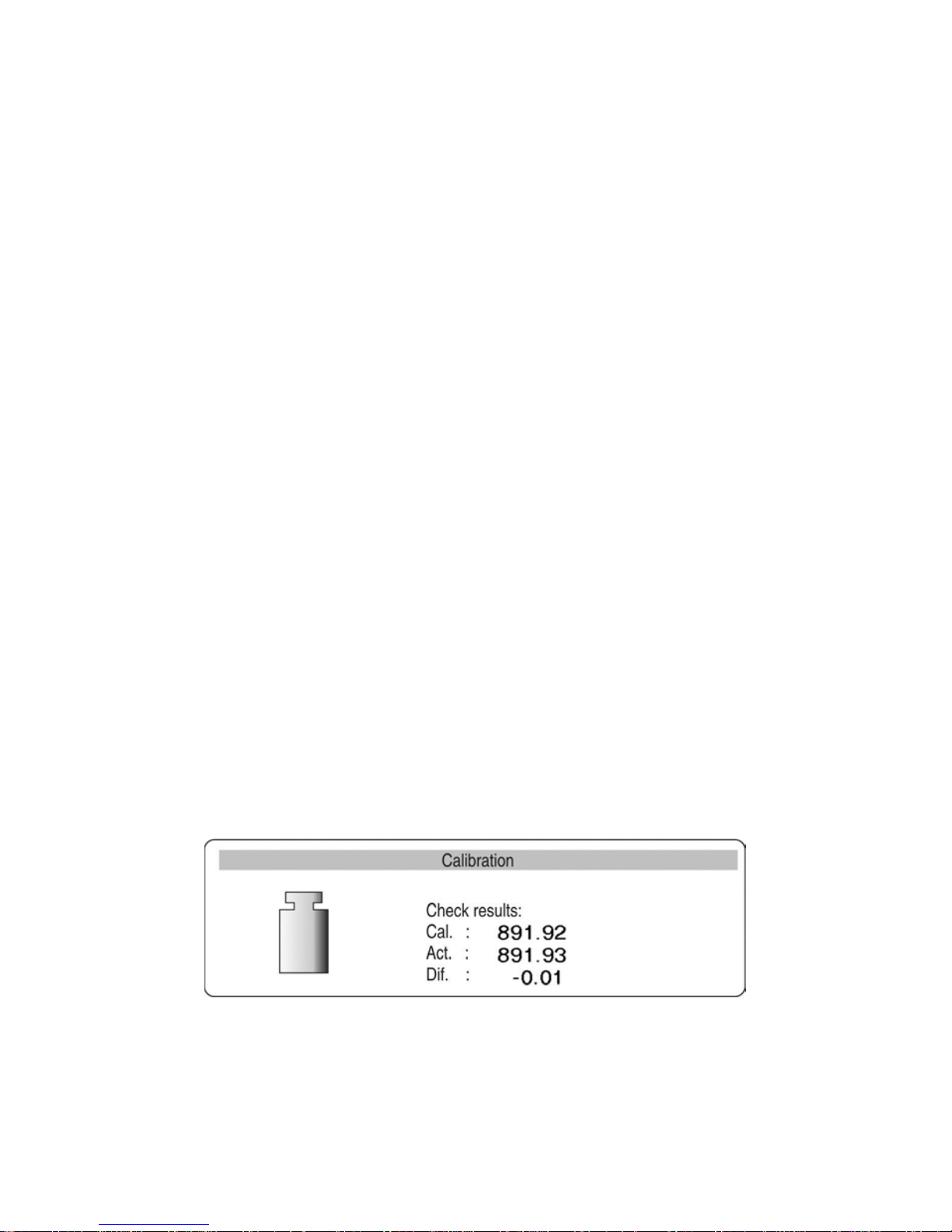
7.2. Adjustment test
Adjustment test is a comparison of internal adjustment weight with its value stored in
balance’s memory. This process is carried out automatically and its result is shown on the
display.
Fig. 13. Adjustment test
Cal. – the value of internal adjustment weight
Curr. – weighing result of the internal adjustment weight
Dev. – deviation calculated between the both values
Page 25

- 25 -
Return to weighing mode
Changes introduced in balance memory will be saved on returning to
weighing with procedure of saving changes. Press ESC key for a few times
until the display shows a question: Save? As displayed, select one of
available options:
ENTER – save changes and go back to menu;
ESC – abandon changes and go back to menu.
(see Fig. 9. Return to weighing mode. point. 5.1.2. Return to weighing
mode).)
7.3. Manual adjustment
7.3.1.
Internal adjustment
1. Go to submenu P1 – Adjustment.
2. Place the marker next to a function 01 Internal adjustment.
3. Press RIGHT ARROW KEY.
4. The balance automatically carries out internal adjustment process. While
adjustment process is in progress do not load the weighing pan with any weight.
5. On completing the internal adjustment procedure the balance saves adjustment
data in its memory and returns to weighing mode.
Caution:
- In order to abort adjustment process press ESC key.
- If during internal adjustment process the weighing pan is loaded, then the balance
displays an error message. The adjustment process is automatically stopped. On
taking off the load from the weighing pan, the process is resumed and completed.
- I f the DRH function is enabled in balance sett ing s, then bala n ce user can not abor t
the adjustment process once initiated.
7.3.2.
External adjustment
The external adjustment in balances AS/X series should be carried out with an external
mass standard / weight class: E
2
.
List of weights / mass standards required for adjusting balances is specified in the
technical data provided at the end of this user manual.
1. Go to menu P1 – Adjustment.
2. Set the marker next to a function 02 External adjustment.
3. Press RIGHT ARROW KEY.
4. The software displays a command to take off any load from the weighing pan (the
weighing pan must by empty). On unloading the weighing pan, press ENTER key.
5. The balance determines mass of an empty weighing pan.
6. Load a weight / mass standard which mass is given on the display and press
ENTER key.
Page 26

- 26 -
7. On completing adjustment process the balance returns to displaying submenu P1
- Adjustment
8. Return to weighing mode – in accordance with point 5.1.2.
If the DRH function is enabled in balance settings, then external adjustment
process is disabled. The DRH function is enabled in verified balances (which are
subject to conformity assessment).
7.3.3.
User adjustment
The external adjustment in balances AS/X series should be carried out with an optional
mass standard / weight class: E
2
.
- Go to menu P1 – Adjustment and set the marker next to a function 03 User
adjustment.
- Press RIGHT ARROW KEY.
- The balance displays a command to enter mass of an adjustment weight. The first
digit of the weight value is flicering, and it is ready for editing.
Fig. 14. User adjustment – declaring weig ht valu e
- Use function kwys (as specified in point 5.1.1 of this user manual) to enter the value
of the external weight/mass standard.
- Accept the weight’s value as entered. The balance initiates adjustment process by
indicating process commands on the display.
- The balances shows a command on determining mass of the empty weighing pan,
which is followed by a command to place a weighed with pre-determined mass.
- On placing the determined weight on the weighing pan accept it by pressing Enter
key.
- On completing adjustment process the balance returns to displaying submenu P1 -
Adjustment.
- Return to weighing mode – in accordance with point 5.1.2.
It is recommended that the mass of an external adjustment weight is
approximately ¾ of balance’s maximum capacity.
If the DRH function is enabled in balance settings, then external adjustment
process is disabled.
Page 27

- 27 -
7.4. Adjustment report printout
On completion of any type of adjustment process, the balance enables preparing a report
from adjustment process. The report can be printed on a connected printer and sent to a
computer and saved in a form of file for records.
P1 08 Report printout : 1: yes – report printout enabled
P1 08 Report printout : 0: no – report printout disabled
Remember, that if the parameter is set for YES, then a report is generated and sent
automatically.
Fig. 15. Submenu: Adjustment
The content of the report from adjustment process depends on settings of GLP
parameters. Any option in the GLP submenu which attribute is YES is included in a report
from adjustment process.
Fig. 16. GLP submenu - settings
Page 28
- 28 -
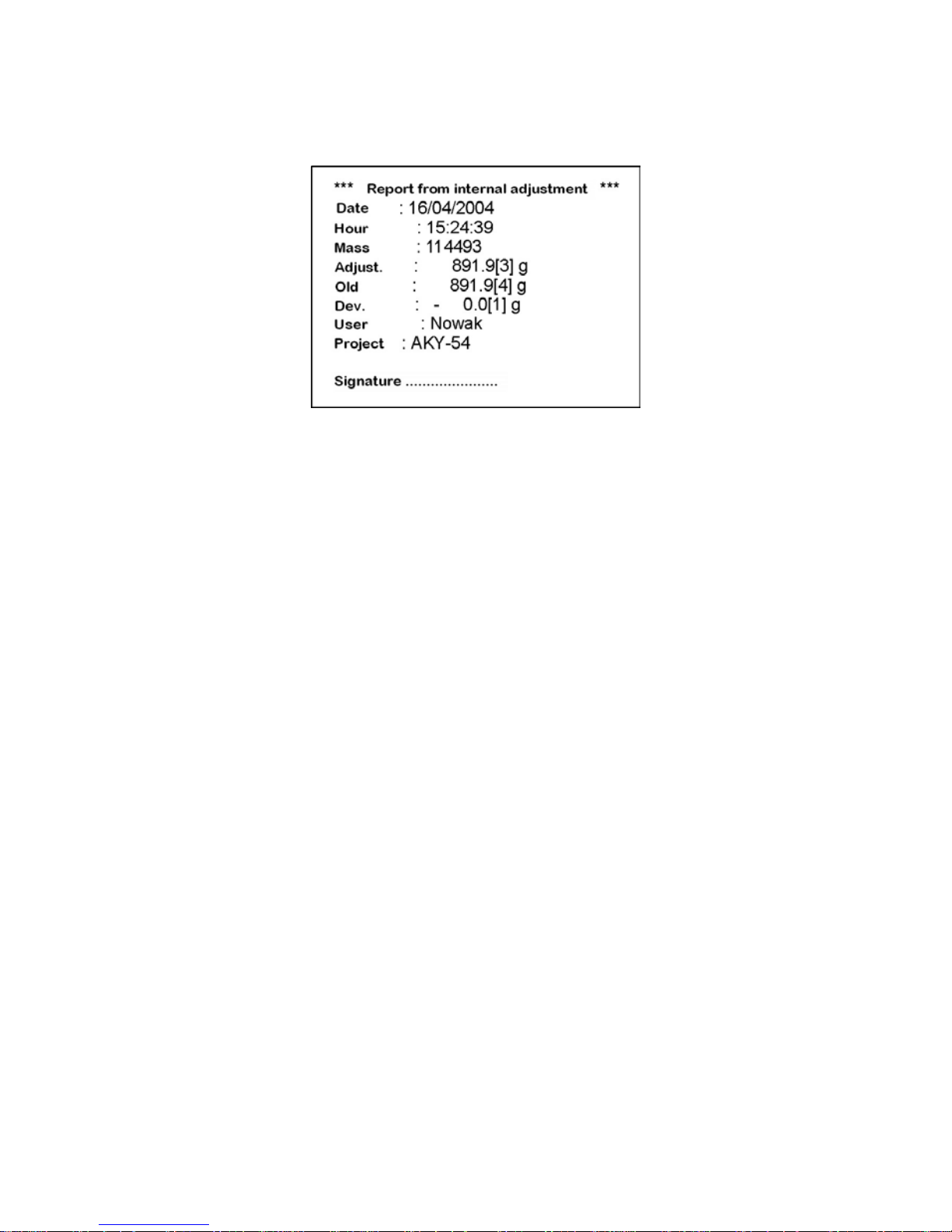
Apart from information set in menu group the report contains: Mass of adjustment weight
stored in balance’s memory from last carried out adjustment (description: Old:) Mass of
adjustment weight determined in current adjustment process (description: Adjustment:)
Adjustment deviation, i.e. difference between the two mass records (description:
Deviation:).
Fig 17. An example of a report from adjustment process
8. DETERMINING CONTENT OF A PRINTOUT FOR GLP PROCEDURES
Menu P2 GLP is group of the parameters which enables declaring variables that are
present on a printout from adjustment process. Fields referring to:
- user (max 8 alphanumeric characters)
- project (max 8 alphanumeric characters)
are editable are enable entering a text using balance’s keyboard or connectable external
computer keyboard PS/2 type. The other fields listed in the GLP are set:
- 1 yes (print on a report)
- 0 no (do not print on a report)
GLP submenu is presented in figure 16. If a user applies an external keyboard PS/2 type,
then the relation between the balance’s keyboard and the computer keyboard are as
specified in point 5.1.3 of this user manual.
Page 29

- 29 -
9. DATE AND TIME SETTINGS
The balance AS/X series features an internal real-time clock, and its parameters are
editable. Go to submenu P3 Date/Time following prompts given on below figure.
Fig. 18. Submenu Date / Time
01 Date format
Enables two types of setting date format:
- 1 date format Month/Day/Year
- 0 date format Day/Month/Year
On selecting appropriate date format accept it by pressing ENTER key.
02 Time format
Enables two types of setting time format:
- 1 time format 12 hours
- 0 time format 24 hours
On selecting appropriate time format accept it by pressing ENTER key.
12 hour time format is differentiated by letters PM or AM present on printouts.
Page 30

- 30 -
03 Time
Press RIGHT ARROW KEY to enter parameter 03 Time, as presented on below figure.
Fig. 19. Submenu Date / Time – setting time
Place the marker next to a value to be edited (Hour, Minute, Second). Activate a field for
editing by pressing RIGHT ARROW KEY. Press UP and DOWN ARROWS to set numeric
values of hour / minute / second.
Fig. 20. Submenu Date / Time – setting time – controlling keys
Accept set value (the last digit stops flickering).
Repeat the activity for other time values. On setting the new time value press ENTER key.
The balance returns to displaying submenu P3 Date/Time. The time value visible in the
upper bar graph of the display is changed.
On setting required time value return to weighing mode as specified in point 5.1.2 of this
user manual.
Page 31

- 31 -
04 Date
Press RIGHT ARROW KEY to enter parameter 04 Data. As specified in the previous point
(03 Time) set current date. On setting required date return to weighing mode as specified
in point 5.1.2 of this user manual.
Fig. 21. Submenu Date / Time – date setti ng
05 Display time
Available settings
1 – YES time displaying enabled, the upper bargraph of the display contains time,
0 – NO time displaying disabled.
06 Display date
Available settings
1 – YES date displaying enabled, the upper bargraph of the display contains date,
0 – NO date displaying disabled.
Return to weighing mode
(see point 5.1.2. – Return to weighing mode)
Page 32

- 32 -
10. SETTING BALANCE OPERATING PARAMETERS
Balance AS/X series, in the menu group <P4 Readout> enables adjusting balance
operation to current ambient conditions at a workstation (filter) and required user needs
(display refreshment, autozero, previewing last digit).
Fig. 22. Submenu Readout – internal settings
10.1. Filter settings
Depending on the ambient conditions at a workstation, the balance enables setting the
filtering value. In case of very good operating conditions it is recommended to set the
filtering value to very fast (parameter value 01 Filter set to 1). If the operating conditions
are harsh (air drafts, vibrations) set the filter to slow or very slow (parameter value 01 Filter
set to 4 or 5). The effectiveness of filter operation differs in relation to the measuring range.
The filter operates with lower accuracy while the mass indication is quickly increasing after
placing a load on the weighing pan. Filter accuracy is increased when weighed mass is
within filter’s set operation range (parameter: filter operation range is available only in
balance’s service menu, and it is inaccessible for the user).
10.2. Value release
Select one of available value release options: fast, fast+reliable or reliable. Depending on
accepted criterion the weighing time will be shorter or longer.
10.3. Time interval of display refreshment
The parameter determines time interval in which display indication is refreshed.
In case of the higher refreshment values, the display does not indicate intermediate and
unstable mass values occurring while loading and unloading weighed mass on the
weighing pan. For low refreshment values the display indicates any changes in the value
of weighed mass – which is required while dosing loose or liquid materials. The time
interval of display refreshment is set in seconds.
Page 33

- 33 -
10.4. Autozero function
In order to ensure balance’s precise mass indication, “AUTOZERO” software parameter
has been introduced. The application of this function is automatic control and correction of
zero indication.
If AUTOZERO function is enabled, then each weighing process starts from precise zero
point. There are, however, some cases when this function can be a disturbing factor of
measuring process; for instance very slow placing of a load on the weighing pan (e.g. load
pouring) – in such case system of zero indication correction can also correct actual
indication of loaded mass. AUTOZERO function is enabled or disabled in parameter P4 03
as specified in point 5.1.1 of this user manual.
10.5. Last digit
In order to ensure adequate operating comfort with a balance, the user can determine
presence of the last digit on the display and criteria of its displaying.
Available settings are:
- 0 never
- 1 always
- 2 when stable
10.6. Negative
The function aids previewing mass value and other indications on the display. Depending
on user needs it is possible to enable or disable the function.
10.7. Air buoyancy correction
The air buoyancy correction enables correcting errors occurring while mass measuring
processes, i.e.:
1.
Determining mass of a sample which density considerably differs from the density of
a mass standard used for adjusting the balance. As standard, the balance is adjusted
with a mass standard made of steel that density equals ~8.0g/cm
3
or made of brass
with density ~8.7g/cm
3
. If the weighed object is made of other materials, then below
specified relationship applies:
Below scheme demonstrates the size of mass corrections in relation to the density of
weighed material, and assuming that air density is constant and equals 1.2 kg/m
3
.
Page 34

- 34 -
Fig. 23. Error value in relation to the density of weighed sample
2. The test monitors changes in mass of a sample within the time of a few hours, if:
mass sample is possibly constant (minor changes). In such case it is assumed, that
considerable effect on the final mass measurement result is caused by changes of air
density, which in turn is strongly affected by pressure, temperature and humidity.
In order to make the measurements reliable, it is necessary to determine the density
of air in the weighing room and the density of weighed object.
Page 35

- 35 -
10.7.1. Means of operation
The software enables two means of using the air buoyancy correction.
1. By inserting to balance memory known value of air density and known density
value of weighed sample.
After inserting these values the application automatically calculates correction
factor for measured mass and after re-calculation of sample mass displays correct
mass value. In order to avoid any errors, the re-calculated mass is proceeded by
and exclamation mark (!) on the display and on a printout.
2. By semi-automatic determining density of the air and inserting the known density
value of weighed sample.
Determining air density requires applying a set of two mass standards, where one
of them is made of stainless steel, and the other of aluminum. Based on mass
indications for both mass standards, the software automatically calculates the air
density which has to be saved in balance memory (by pressing Enter key). Then
insert density value of the weighed sample to balance memory.
After inserting these values the application automatically calculates correction
factor for measured mass and after re-calculation of sample mass displays correct
mass value.
As in previous case the re-calculated mass is proceeded by and exclamation
mark (!) on the display and on a printout.
The air buoyancy correction mode is enabled or disabled in the user menu.
The mode can operate together with other working modes, like checkweighing, dosing,
etc.).
10.7.2. Activating air buoyancy correction
Fig. 23-1. Balance menu – enabling air buoyancy correction
Page 36

- 36 -
Set value of parameter P4 07 Air buoyancy correction to 1: yes
After returning to weighing mode with procedure of saving changes the display indicates
pictogram (!). From now on the displayed mass is corrected in relation to buoyed air and
density of weighed sample.
Fig. 23-2. Balance menu – enabling air buoyancy correction
In order to correct the mass of weighed object using air buoyancy correction mode,
remember to apply current density values of the air and the weighed sample.
10.7.3. Determining the coefficient value for known density of air and
weighed sample
If the balance is connected with an external PC keyboard PS/2 type, that the same
operation is initiated by pressing [Insert] key on the PC keyboard. The balance displays a
window for entering the density values of air and weighed sample.
Fig. 23-3. Display in air buoyancy correction mode – entering density of weighed
sample and air.
roS – density of weighed sample
roA – density of air
After entering the density values return to weighing mode by pressing ENTER key.
Page 37

- 37 -
10.7.4. Coefficient determining process using a set of mass standards
CAUTION:
Before carrying out the process it is neces sary to disabl e AIR BUO YAN CY CORREC TIO N
MODE if it was in use.
Determining air buoyancy correction is also carried out using a dedicated set of 2 pieces of
mass standards. One of the mass standards is made of stainless steel, and the other of
aluminum. Each of the mass standards has specifically determined mass and density.
Determining procedure:
1. Enter the density mode.
Fig. 23-4. Air density – mode selection
2. After entering the mode select appropriate procedure
Fig. 23-5. Air density – selecting appropriate mode settings
Page 38

- 38 -
3. On entering mode settings, set required data (mass and density) in the
corresponding fields
Fig. 23-6. Air density – declaring values of mass and density
4. After inserting all required data start the determining procedure – move the
marker to the START field and press F key
5. Load the weighing with the stainless steel mass standard and on stabilization of
measurement result press ENTER key
Fig. 23-7. Air buoyancy correction – determining mass of a stainless steel
mass standard
6. Mass of the stainless steel standard is saved in balance’s memory. Unload it from
the weighing pan, and load the aluminum mass standard. On stabilization of
measurement result press ENTER key
Fig. 23-8. Air buoyancy correction – determining mass of an aluminum mass
standard
Page 39

- 39 -
7. The density of air is calculated automatically.
Fig. 23-9. Air buoyancy correction – the air density correcting coeff ic ient
At this stage the user can:
− Restart the procedure from the beginning (by pressing Units key)
− Return to weighing without saving changes on air density determination
(press MODE key and select mode WEIGHING)
−
Accept calculated density value.
Fig. 23-10. Air buoyancy correction – Message window
8. The display indicates the calculated values – the balance is ready for operation
with the determined air density coefficient.
9. Return to weighing by selecting WEIGHING mode.
10. Set the attribute of air buoyancy correction to YES
Page 40

- 40 -
Fig. 23-11. Air buoyancy correction – mode activation
10.8. Operating conditions
This parameter enables two settings: stable or unstable. Setting the parameter to stable
causes much faster operation of the balance, i.e. the weighing time is shorter than
compared to setting: unstable. This parameter refers to operating and ambient conditions
at a workstation. If the conditions are unstable, then it is recommended to set the
parameter to unstable. The default setting of the parameter is: stable.
Page 41

- 41 -
11. RS 232 FUNCTIONS
Balance AS/X series enables defining parameters of balance communication with a
computer or a printer.
Fig. 24. Submenu RS 232 - settings
01 Interface / 0 : RS232 1 : USB* 2 : RS232+USB*
02 Baud rate / 0 : 2400 1 : 4800 2 : 9600 3 : 19200
03 Parity / 0 : no 1 : even 2 : odd
04 Data bits / 1 : 7 bits 2 : 8 bits
05 stop bits / 1 : 1 bit 2 : 2 bits
06 Automatic printout / 0 : no 1 : continuous 2 : with interval 3: when stable
07 Interval the interval determines the period of time in which the
balance sends display indication to a printer/computer. The
interval is set according to a relation x 0.1 s = interval time).
The available range of the parameter setting from 1 to 9999.
08 Min mass Minimamum mass for enabling automatic operation of the
RS 232. The following measurement data is sent only if
taking off the load the mass indication returns below the set
value mininum threshold
09 Print stable 0 : no 1 : yes
10 Printer type Epson or standard
11 Paper cut Available only in EPSON printers featuring this function. If
the function is set to YES then paper cut option is carried out
automatically.
12 Delete statistics /0: no 1: on header 2: on footer
The option is enabled in <STATISTICS> mode, where the
header is printout no.1, and the footer is printout n o. 2.
Means of des ig ning the printouts and operation of
<STATISTICS> mode is described further in this user
manual.
* - only in non legalization balances
On setting appropriate parameter values return to the weighing mode in accordance with
point 5.1.2. of this user manual.
Page 42

- 42 -
12. PRINTOUTS
Printouts menu is dedicated for creating non-standard printout templates and selecting
type of a printout which is printed. Detailed description of non-standard printouts is
provided in point 17 of this user manual.
13. SETTING ACCESSIBILITY OF MEASURING UNITS
All measuring units which attribute is set to 1: yes
are accessible from the main menu level under a key for toggling between the measuring
units.
The measuring units described as 09 Taele Hk., 10 Taele S., 11 Taele T . the following
relations occur:
• If the attribute of all three measuring units is set to 1: yes, then the software will
display only the first one, i.e. 09 Taele Hk
If the measurement should be carried out using 11 Taele T unit, then the attribute
of the other two units should be set to 0 : no
Enter group of parameters P7 Units in accordance with point 5.2.7.
Fig. 25. Measuring units - settings
After setting the required parameter values return to weighing mode in accordance with
point 5.1.2. of this user manual.
Caution:
In case of verified balances the available measuring units are limited to: [g], [mg], [ct] –
even if set to 1 – YES in balance’s menu.
Page 43

- 43 -
14. SETTING ACCESSIBILITY OF WORKING MODES
This group of parameters enables setting accessibility of working modes, which are
available for an operator after pressing the Mode key on balance’s overlay.
Fig. 26. Working modes – settings
All working modes which attribute is set to 1: yes are accessible from the main menu level
under a key for toggling between the working modes. Changes to the parameter values are
carried out in accordance with point 5.1.1 of this user manual.
15. OTHER PARAMETERS
Depending on user needs the balance enables setting parameters influencing its operation.
These parameters are grouped in menu P9 Other, for instance: beep sound on pressing a
key/button, screen contrast, etc. Enter submenu P9 Other by acting as in case of point 14.
01 ID settings
The submenu contains 6 codes each comprising 6 digits. The codes are used in
printouts for specifying a product, operator, product batch, etc.
02 Automatic I D Printo u t
If set to YES, then it prints all numeric codes. If set to NO, then the codes are not
printed.
03 Beep sound
Determines whether each pressing of a key/button on balance overlay is confirmed by
a beep sound, available settings: YES/NO.
Page 44

- 44 -
04 Language
Selecting language version of software menu, available settings Polish or English
05 Backlight
Determines whether the backlight of the balance’s graphic display should be enabled
or disabled (enabling the backlight option improves data visibility on the display)
06 Screen brightness
Enables changing the brightness of the balance’s graphic display – entering the
function opens a window for setting brightness level using buttons on the balance’s
overlay
07 Screen contrast
Enables changing the contrast of the balance’s graphic display – entering the function
opens a window for setting contrast level using buttons on the balance’s overlay
08 Screen saver
Switching on the screen saver causes blanking displayed values after a set amount of
time. The indication on the display does not change while blanking.
08 Temperature
This function serves for information purpose only, and it enables previewing
temperature value that is measured inside the balance by a sensor. Return to menu
by pressing ESC key.
10 Balance no.
This function serves for information purpose only, and it enables previewing factory
number of a balance.
11 Software no.
Enables previewing number of software revision operating in a balance.
12 Parameter printout
Enabling this function causes printing balance parameters set in the user menu. The
user specifies numbers of parameters that should be printed.
Fig. 27. Submenu Others – parameter printout
On entering this option and selecting user settings, the balance starts sending current
parameter values to a connected printer via RS 232 interface
Page 45

- 45 -
13 Acquire (upload) parameters
Enabling this function causes uploading all parameters sent via RS 232 interface from
a connected computer. On completing uploading process the balance informs a user
on number of accepted and changed parameters, and number of incorrectly declared
parameters which are rejected by the balance. Printing and uploading balance
parameters is a very simple and intuitive means of setting new values of balance
parameters. On printing to a file current parameter values on a connected computer,
the user can simply and quickly change parameter values. After saving made
changes, the updated file is sent from the computer level to balance’s software. On
completing of uploading process and saving changes the balance accepts new
parameter settings. The procedure requires that a user is familiar with balance
parameters and has good knowledge of computers.
14 Password protection
This submenu enables setting a password limiting access to a balance for an
Administrator and a user (see point 7.2. of this user manual: USER LOG IN)
Page 46

- 46 -
16. WORKING MODES
16.1. Parts counting of the same mass
The parts counting mode can be carried out suing three means:
- inserting mass of a single part
- determining mass of a single part from a standard quantity
- selecting a part for counting from balance’s database
16.1.1.
Counting by inserti n g mass of a single part
Activate parts counting mode (see Fig. 30).
Fig. 28. Parts counting – main menu
Set reference mass and press ENTER key or move the cursor next to the field 07 Start and
press RIGHT ARROW KEY. The display indications change to specific for the parts
counting mode.
Fig. 29. Parts counting – display content
APW – mass of a single part [g]
WGH – mass of all parts placed on balance’s weighing pan
pcs – marker of the parts counting mode
Page 47

- 47 -
Return to weighing mode
- Press MODE key, the display indicates list of available working modes
- Move the cursor next to a field: MO Weighing
- Press RIGHT ARROW KEY, the software returns to weighing mode and displays
current measurement result
16.1.2.
Counting by determining mass of a single part from a
standard quantity
Enable parts counting mode as described in point 16.1.1. independently on mass that has
to be specified in field 01. Move the cursor next to a field 07 Start and press RIGHT
ARROW KEY. While in parts counting mode press F key. The display opens a window for
specifying standard quantity of counted parts (fields 01 – 04) or set the standard quantity in
field 05 – Sample.
Fig. 30. Counting by determining mass of a single part from a standard
quantity
Next, press RIGHT ARROW KEY and follow commands presented on the display.
Fig. 31. content with enabled AAC function
Page 48

- 48 -
1- mass of a single part
2 - mass of all counted parts
3 - the pictogram of enabled Automatic Accuracy Correction function
The display indicates mass of counted parts, that are loaded on balance’s weighing pan
(i.e. 10 parts). If the added amount of parts is below the currently counted one, then the
software automatically corrects mass of a single part. In this case it is APW = 5.2282
corrected to 5.1837. from now on the following parts are counted according to the new
mass of a single part.
This means enables counting mass of a single part from a standard quantity.
The software comprises four conditions for operation of
Automatic Accuracy Correction function
1. After adding the number of parts placed on balance’s weighing pan must be
greater than before adding
2. After adding the number of parts loaded on balance’s weighing pan must be less
than twice the quantity which was indicated on the display before adding
3. current quantity of parts must contain within a tolerance ± 0,3 of the total value,
4. stable measurement result.
If a user claims, that standard quantity is sufficient, it is possible to save the mass of a
single part in balance’s memory by pressing RIGHT ARROW KEY on balance’s overlay.
Fig. 32. Automatic Accuracy Correction – saving single par t m ass in the
database
Set the cursor next to a desired field and insert name for weighed parts. Press Enter key
(for saving the name) and Enter key (for saving the value). Next to the inserted name there
Page 49

- 49 -
is mass of a single part. Now the record in the database is ready for recalling by using field
02 Recall standard
16.1.3. Selecting a part for cou n ting from balance’s database
Enable parts counting mode in accordance with below figure.
Fig. 33. Selecting a part for counting from the database
Select a record from the database, and start part counting process.
Page 50

- 50 -
16.2. Checkweighing
Checkweighing is a process intended for precise determining mass of a weighed sample
with set and enabled checkweighing thresholds (limits). The thresholds are to visualize (by
means of a bargraph located on the left side of the display) and monitor checkweighing
process.
Mode activating
Fig. 34. Checkweighing – mode activating
Display content
Fig. 35. Checkweighing – display content
1 – measurement result
2 – bargraph
3 – working mode name
4 – difference between mass of weighed sample and the center of the tolerance field
(HI/LO)
5 – the values of low (LO) and high (HI) checkweighing thresholds
6 – a pictogram indicating the weighing range of currently weighed sample
(available indications: LO, OK and HI)
Page 51

- 51 -
Remember to set the 02 Hi Threshold first, as the software automatically checks
whether inserted values are correct and hold within the measuring range of a
balance.
If set values are recognized by the software as incorrect, the balance displays an error
message and returns to parameter settings without saving changes.
Checkweighing with use of database of thresholds (limits)
Checkweighing process can be carried out with use of the DATABASE OF THRESHOLDS,
which is a programmable collection of records comprising:
− 500 records
− Name of a product in each record (max 10 alphanumeric characters
− The value of HI threshold for each record
− The value of LO threshold for each record
Programming the database of thresholds
Fig. 36. Checkweighing – submenu content
− Move the cursor to a field “Database of thresholds (limits)” and press RIGHT
ARROW KEY
− Select number of a record by moving the cursor next to a desired field and press
RIGHT ARROW KEY
Fig. 37. Checkweighing – programming database of thresholds
Page 52

- 52 -
− Move the cursor to a field “Database of thresholds (limits)” and press RIGHT
ARROW KEY
Fig. 38. Checkweighing – programming database of thresholds –
inserting thresholds values
− Enter a name for a selected record (name of a product to be weighed)
− Enter the value of HI threshold (limit)
− Enter the value of LO threshold (limit)
− Accept entered values by double pressing of ENTER key
Fig. 39. Checkweighing – mode operation with enabled checkweighing
limits
− Move the cursor to a field “START” and press RIGHT ARROW KEY
− The balance is ready to weigh a product with set checkweighing thresholds (limits)
Page 53

- 53 -
Fig. 40. Checkweighing – display content
1 – measurement result
2 – pictogram of stable measurement result
3 – working mode name
4 – the value of HI threshold (limit)
5 – the value of LO threshold (limit)
6 – a pictogram indicating the weighing range of currently weighed sample
(LO – OK.- HI)
7 – name of a product saved in the database of thresholds
8 – difference between the measurement result and the center of set tolerance field
9 – a pictogram indicating the current “place” of weighed sample in relation to set
checkweighing thresholds (limits)
10 – a bargraph indicating the range of applied measuring range of a balance.
Selecting other product from the database of thresholds (limits)
− While in checkweighing mode press SETUP key
− A message box is opened on the display. Go to the database of thresholds (limits)
and select another record from the database or set other HI and LO thresholds
values if the database is disabled)
Page 54

- 54 -
16.3. Filling (dosing)
Filling (dosing) mode is intended for precise measuring or adding a product until reaching a
pre-defined target value. Before the beginning of a measuring cycle the user should set a
target mass, which is simultaneous the HI dosing threshold.
Mode activating
Fig. 41. Filling – mode activati ng
Display content
Fig. 42. Filling – display conte nt
1 – mass to be placed on the weighing pan to reach a pre-defined target value
2 – bargraph
3 – working mode name
4 – TR (target) the value of target mass which is declared in mode parameters
(see Fig. 38. M3 01 Target mass)
5 – WGH mass currently placed on balance’s weighing pan
Page 55

- 55 -
16.4. Percent setup
The purpose of this working mode is comparing mass of a weighed load with reference
mass which is specified in mode settings. The result of the comparison process is
displayed in percent.
Working mode Percent Setup can cooperate with additional working modes:
checkweighing, dosing and statistics.
Mode activating
Fig. 43. Percent setup – mode activating
Display content
Fig. 44. Percent setup – display content
1 – percent value, i.e. relation between mass of a load placed on balance’s weighing
pan and reference mass saved in parameter settings
2 – working mode name
3 – REF – reference mass (see Fig. 40 – M4 01)
4 – WGH mass currently placed on balance’s weighing pan
Page 56

- 56 -
Percent setup in cooperation with other working modes
While activating the working mode go to its settings and set parameters: M4 03, 04, 05 to
YES. Then move the cursor next to START field and start working mode operation.
Caution:
- On enabling the Checkweighing mode in working mode settings remember to set
the HI and LO checkweighing thresholds (lim its) as val ues expres sed in %.
- On enabling the Dosing mode in working mode settings remember to set the
target value expressed in %.
- On enabling Statistics mode in working mode settings remember to move the
cursor to a field: Erase to erase previous statistics, and then move the cursor to
a field Statistics and change its attribute from NO to YES. Accept the settings by
pressing Enter key.
Fig. 45. Percent setup – cooperation with other working modes
1 – percent value, i.e. relation between mass of a load placed on balance’s weighing
pan and reference mass saved in parameter settings
2 – pictogram of stable measurement result
3 – working mode name
4 – REF reference mass
5 – WGH mass currently placed on balance’s weighing pan
6 – a pictogram indicating the weighing range of currently weighed sample
(LO – OK.- HI)
Page 57

- 57 -
7 – statistics mode enabled (N=0 – equals to no measurement records in current
statistics)
8 – dosing mode enabled (load mass between 90 – 110%)
On completing a measurement series, e.g. 10 measurements (no, of measurement
N=10) the user can preview the result of carried out statistics from the measurement
series.
− Enter working mode submenu
− Set the cursor next to a parameter 05 Statistics
− Press F key to enter the parameter 05 Statistics
− Set the cursor next to a parameter 02 Results
− Enter the parameter to preview results from completed statistics
− Press ENTER key to print statistics result on a connected printer/computer
− Return to working mode submenu and higher menu levels by pressing ESC
key
Fig. 46. Percent setup – cooperation with other working modes –
Statistics
Determining reference mass by weighing a standard
The percent setup mode enables determining reference mass by weighing an accepted
standard.
In such case, when in the main mode window press F key. The software initiates the
procedure by displaying a command. Follow this and other commands visible on the
display.
On completing the procedure the software automatically returns to displaying the main
window of the percent setup mode.
Page 58

- 58 -
16.5. Animal weighing
Mode activating
Fig. 47. Animal weighing – display content
Internal mode settings
- FILTER (determines the speed (weighing time) required for stabilization of the
final measurement result, the faster the filter setting, the shorter the measurement
time.
- THRESHOLD (its value is expressed in balance reading units, it is the value
below which the weighing results must come down to automatically enable the
following measurement of weighed object)
- AUTO START (the function used for automatic startup of the following
measurement processes)
- STATISTICS (calculation of statistics for each weighed object)
- RUN (Start measuring process)
Page 59

- 59 -
16.6. Density determination of solids and liquids
Additional equipment of a balance AS/X series includes a kit dedicated for determining
density of solids and liquids.
Fig. 48. Components of a density kit
Components of a density kit:
1. Beaker basis. 8. Hook.
2. Stand for weighing
pans.
9. Top weighing pan for determining
density of solids.
3. Sinker. 10. Pans flexible connection.
4. Beaker.
11. Bottom weighing pan for determining
density of solids.
5. Thermometer handle. 12. Supplementary weights
6. Thermometer.
13. Additional stand for a set of pans or a
sinker
7. Sinker’s flexible
connection.
14. Additional set of pans for determining
density of solids, which density is lower
than density of water.
Page 60

- 60 -
16.6.1. Density determining o f liquids
The basic component needed for determining density of liquids is a glass sinker with
precisely determined volume, which value is indicated on sinker’s hook.
Before carrying out density determining process enter the sinker’s volume value to
balance’s memory.
The density determining process is based on comparing mass of the sinker, first by
weighing it in the air, and second by immersing it in the tested liquid.
The result of liquid density is automatically calculated by the balance software, and
indicated on its display.
The measurement result can be sent for multiple times to a connected printer or computer
via RS 232 interface and on pressing PRINT key
16.6.2.
Density determining of solids
Density of solids can be determined in one of three types of liquids:
− WATER (distilled water),
− ALCOHOL (spirit 100% +/- 0.1% in reference temperature: 20 °C),
− OTHER (another liquid with known density)
The density determining process is based on comparing mass of a sample, which is first
weighed it in the air (i.e. placed on the top weighing pan) and mass of the same sample
which is immersed in the liquid (i.e. placed on the bottom weighing pan of the density kit).
Based on obtained measurement results, the software calculates the density of tested
sample and indicates on the balance’s display. The measurement result can be sent for
multiple times to a connected printer or computer via RS 232 interface and on pressing
PRINT key
Detailed description of the density determining process is described in the user
manual attached to the kit for determining density of solids and liquids.
Page 61

- 61 -
16.7. Formulation
Formulation mode is intended for preparing mixtures in accordance with pre-defined
formulas. It is highly recommended for pharmacies. The software of balance XA/2X series
features calculation memory, therefore it stores mass of each ingredient of a mixture and
sums of weighed ingredients.
While using formulation mode the balance’s display shows and continuously updates
the following data:
1. Mass of a load placed on balance’s weighing pan
2. Name of currently weighed ingredient (max 10 characters)
3. “WGH” Mass to be added while weighing a specific ingredient
4. “IC” Number of ingredients which are already weighed in a prepared mixture
5. “SUM” Sum of ingredients mass which are already weighed in a prepared mixture
Mode activating
Fig. 49. Formulation – interna l m ode settin gs
parameter 01 Prompts (Hints)
on enabling, the balance’s graphic display indicates name and mass of each weighed
ingredient in a formulation, i.e. data specified in parameter 04 Formulation
parameter 02 Automatic printout
on enabling the parameter, and on confirmation the software automatically sends mass of
each weighed ingredient via RS 232 interface to a connected printer or computer
Page 62

- 62 -
parameter 03 No. of ingredients
here the user can set number of ingredients in a prepared mixture (maximum no. of
ingredients: 20)
parameter 04 Formulation
entering this parameter settings opens another submenu for specifying names (max 10
characters) and settings (target mass) for each ingredient in a prepared mixture.
parameter 05 Formulation printout
enabling this function causes printing parameters of an active formulation on a connected
printer. The printout contains names and settings of each ingredient in a formulation and
total sum of a complete formulation.
parameter 06 Statistics
enabling (YES) or disabling (NO) of statistical calculations.
CAUTION:
The statistical calculations refer only to the total mass of prepared mixture (mass of each
ingredient in a formulation is not included in the statistics).
parameter 07 Start
startup of Formula making mode
Display content in formula making mode
Fig. 50. Formulation – display cont ent
1 – previewing mass currently placed on balance’s weighing pan.
2 – pictogram of stable measurement result
3 – working mode name
4 – target mass of the currently weighed ingredient, as specified in the parameter
04 Formulation
5 – Sum of all weighed ingredients of a formulation which are saved in balance’s
calculating memory
6 – Number of already weighed ingredients in a prepared formulation
7 – name of currently weighed ingredient
8 – bargraphs on the left side of the display, which denote the mass to be added
(dosed) to reach pre-defined mass of each weighed ingredient. While reaching
the target mass the descriptions on accuracy visible on the bargraph are
changing.
Page 63

- 63 -
Fig. 51. Bargraphs – automatic scaling
Means of preparing mixtures – in accordance with dat a set in worki ng mod e settin g s
on ingredients and their mass
Go to parameter 04 Formulation and enter names and mass of the ingredients in a
formulation. Remember the following conditions:
− Each name can comprise maximum 10 characters,
− Each name has to be accepted by pressing ENTER key, and next set ingredient’s
mass to be weighed in a formula making process
Fig. 52. Declaring a formulation
Page 64

- 64 -
− Total mass of a prepared formulation and mass of the vessel in which the
formulation is prepared must not exceed maximum measuring range (max.
capacity) of a balance
− A formulation can contain maximum 20 ingredients
− Parameter 03 No. of ingredients enables specifying number of the ingredients in a
prepared formulation
− Remember that maximum number of ingredients in a formulation is 20
− While preparing a formulation the software orders dosing the ingredients in
accordance with the their sequence as set in parameter 04 Formulation; e.g. if a
user sets 10 ingredients in parameter 04 Formulation, and then sets no. of
ingredients in a formulation to 8, then the software will complete formula making
process after weighing the first 8 ingredients.
− The software prepares a list of ingredients in accordance with the sequence set in
parameter 04 Formulation, and always starts the formula making process from the
first ingredient on the list, and ends the process on an ingredient number as set in
parameter 03 No. of ingredients.
− If a user needs a documentation from a formula making process, e.g. in a form of
a printout, then set parameter 02 Automatic printout to 1 : YES. In such case
each accepted mass of an ingredient (by pressing UNITS key) is automatically
printed on a connected printer or computer.
• Set parameter 01 Prompts (Hints) to 1 : YES.
• Enter Formulation mode by pressing ENTER key.
• Tare mass of a vessel for formula making process.
• Weigh the first ingredient of a formulation (ingredient’s mass is visible in the WGH
field)
• Press UNITS key. Mass of the first ingredient is saved in balance memory. The
parameters visible on the display will change to:
ingredient 2, mass WGH, IC=1, SUM=. . . .
• Mass indication on the display will zero.
• Repeat the process for all the ingredients set in a formulation
• After weighing the last ingredient of a prepared formulation and saving its mass in
balance memory (by pressing UNITS key) the display automatically changes to
the total mass of prepared formulation. The mass value is also locked on the
display, and there are prompts on possible activities.
Page 65

- 65 -
Means of preparing mixtures without entering data to balance memory on formation
ingredients and their mass
If a user needs a documentation from a formula making process, e.g. in a form of a
printout, then set parameter 02 Automatic printout to 1 : YES.
In such case each accepted mass of an ingredient (by pressing F key) is automatically
printed on a connected printer or computer.
• Set parameter 01 Prompts (Hints) to 0 : NO.
• Enter Formulation mode by pressing ENTER key
• Tare mass of a vessel for formula making process
• Pour an ingredient no. 1 to the vessel until reaching desired target value (follow
criteria on prepared formulation).
• Press F key. Mass of the first ingredient is saved in balance memory. The
parameters visible on the display will change to: IC=1, SUM=. . .
• Mass indication on the display will zero.Press F key.
• Repeat the process for all the ingredients set in a formulation
• After weighing the last ingredient of a prepared formulation press
→
0/T← key.
The formula making process is completed. The indication with total sum of
prepared formulation is locked on the display.
• Press PRINT key to print (send) a report from a completed formulation to a
connected printer of computer.
Statistical calculations
Statistical calculations are carried out only on total mass of prepared formulation (mass of
each ingredient in a formulation is not included in the statistics). If a user wants to run
statistics if the formula making mode, then:
1. Go to parameter 06 Statistics
2. Erase results of previous statistical calculations
3. Set parameter 06 Statistics to YES
4. Enter the formula making mode
5. Carry out required series of measurements
6. Once again go to parameter 06 Statistics
7. Enter parameter 06 02 Results
8. In order to print statistics press PRINT key
Page 66

- 66 -
16.8. Statistics
Mode activating
Fig. 53. Statistics – mode activation
The very first process after entering the Statistics mode should be erasing the results of
previous statistical calculations. It is carried out by using option M8 01 Erase.
All statistical data are updated on an ongoing basis after saving a measurement result in
balance memory. Adding another measurement to a series is carried out on placing a
weighed load on balance weighing pan, stabilization of measurement result (the measuring
unit appears on the display) and pressing ENTER key.
The user determines whether statistical data should be visible on the graphic of a balance
display while carrying out the measuring process. This parameter is set in statistics mode
submenu (the data is visible on setting the parameter to “YES”). Independently on the
settings (YES / NO) on the printout of final result of statistical calculations (enabled by
pressing F key) comprises the following data:
N : 5 (number of measurements)
SUM : 161.121 g (total mass of all statistical records in a measured series)
X : 32.224 g (average mass of all statistical records in a measured series)
MIN : 20.486 g (minimum mass)
MAX : 35.578 g (maximum mass)
D : 15.092 g (difference Max- Min)
SDV : 6.581 g (standard deviation)
RDV : 20.4 % (variance factor)
Page 67

- 67 -
Fig. 54. Statistics – display content includ ing a serie s of mea surem ents
1. Mass currently placed on the weighing pan
2. Number of measurement in a measuring series
3. Sum of all completed measurements in a series
4. Average mass of all completed measurements in a series
5. Minimum saved mass in a carried out measuring series
6. Maximum saved mass in a carried out measuring series
7. The difference between the minimum and maximum saved mass in a measuring
series
8. Precisely calculated standard deviation value
9. Variance factor value
10. Measuring unit [g]
11. Working mode name
Statistics mode features a special option enabling quick calculating of statistics from a
measuring series with a possibility of generating reports from the completed calculations.
The user can declare the content of a header and footer in a printout of statistical report.
The header <PRINTOUT 1>, and the footer <PRINTOUT 2> are settable in non-standard
printouts.
In order to correctly use the option, the user has to create templates 1 and 2 using the non-
standard printouts (see point 19.2). As the templates are ready, the option can be enabled
in mode settings.
Means of operation:
− Press key to print the header (PRINTOUT 1)
− Carry out a measuring series (set all options of the GLP menu to NO), and accept
each measurement result by pressing <ENTER> key
− On completing a measuring series press F key to print a statistics from the series
− In order to continue the measuring series accept it by pressing <ENTER> key or
− Press key to print a footer (PRINTOUT 2)
Page 68

- 68 -
For the purpose of increasing the speed of statistical calculations it is possible to enable
the option of automatic erasing statistics. The option is set in parameter: P5 (RS 232) 12
<Erase statistics>.
0 - no (the statistics are not erased. Erasing is carried out by entering mode settings and
selecting option <ERASE>
1 – on header (the statistics is erased directly on pressing key which precedes
printout of a header)
2 – on footer (the statistics is erased directly on pressing key after printing a footer).
16.9. Calibration of pipettes
The mode enables calibrating pipettes of fixed and adjustable volume. On calibration
process, the software determines accuracy error and repeatability error.
In case of pipettes with adjustable volume the errors are determined for Max, Min and ½
Max volume.
All pipettes are checked for their conformity with accuracy and dosing repeatability
specified in the standard EN ISO 8655:2003.
For the purpose of ensuring the highest accuracy it is recommended to maintain the
following ambient conditions:
Ambient temperature for a pipette, tips and liquid should be stabilized within
20°C ÷ 25°C and the change ratio during calibration process should not exceed ±
0.5.°C
Relative humidity 50 ÷ 75%
Use distilled water during pipette calibration procedure.
Page 69

- 69 -
Mode activating
Fig. 55. Pipette calibration – mode activating
Before startup of pipette calibration process set:
- Pipette type [volume: fixed / adjustable]
- Pipette volume Vmax [ml]
- Pipette volume V1/2max [ml]
- Pipette volume Vmin [ml]
- Volume error at Vmax [%]
- Volume error at V1/2max [%]
- Volume error at Vmin [%]
- Liquid temperature [oC]
- Atmospheric pressure [hPa]
- Humidity [%]
- Number of samples
Page 70

- 70 -
Display content
Fig. 56. Pipette calibration – display content
1 – measurement result
2 – working mode name
3 – tested volume
4 – average volume
5 – accuracy error
6 – number of samples (measurements)
The procedure is completed by determining the accuracy error [ES], standard deviation [sr]
and repeatability error [CV].
On each checking procedure the graphic display of a balance indicates the checking result.
Fig. 57. Pipette calibration process – summary
Page 71

- 71 -
Press PRINT key to print a report from pipette calibration process.
Fig. 58. Report from a completed pipette calibration procedure
Page 72

- 72 -
17. PRINTOUTS
17.1. Standard printout
A balance AS/X series features 2 basic types of printouts. The first one is a standard
printout which comprises of a measurement result and all variables set in the GLP
submenu which attribute is set to YES. In case of fields User and Project the user can
enter alphanumeric data.
Fig. 59. Declaring variables for a standard printout – submenu GLP
An example of a standard printout:
Fig. 60 an example of a standard printout
(all options in the GLP menu are set to
YES, i.e. present on a printed)
Fig. 61 an instance of a standard printout
A question mark (?) preceding the mass of a measured load on a printout indicates that the
result was unstable.
Page 73

- 73 -
17.2. Non-standard printouts
Principles of creating non-standard printout templates:
− balance enables creating up to 4 custom printout templates,
− each template must have the string of text start and end specified, e.g. Printout
no. 1 Start – 1 and Printout no. 1 Stop – 40. In this case the Printout no. 1
contains text strings from 1 to 40.
− Next insert the texts into the specified text strings, i.e. 1 ÷ 40.
it is recommended to use an external computer keyboard connected to balance’s
port. This means of text input is much simpler and quicker.
− Non-standard printout templates may overlap each other, i.e.:
Printout 1 Start – 1
Printout 1 Stop – 40
Printout 2 Start – 20
Printout 2 Stop – 40
− Non-standard printout templates are easily created using printout editing
option.
Caution: while text input it is necessary to add all required special signs, such as CRLF,
tabulator, etc. When using printout editing option, all of the special signs are selectable
from available menu. they are grouped on the one side of text editing option, and
included in a printout by adding them to the field Printout.
Fig. 62. Menu Printouts – mode activating
A non-standard printout can contain:
− Variables dependent on an enabled working mode and other user needs (mass,
date, project no.)
− Texts inserted in balance’s user menu
− A custom non-standard printout can contain up to 640 characters inserted in 80
text strings, 8 character each. (starting with parameter String 1 to String 80). A
balance user can create up to 4 non-standard printout templates.
Page 74

- 74 -
17.2.1. Inserting text into strings
Variables available in all working modes and having the same value
%%
Printout of a single character “%”
%N Current net mass in basic measuring unit
%d Current date
%t Current time
%i Balance factory no.
%R Software no.
%P Project no.
%U User no.
%F Name of an active working mode
%C Date and time of last completed adjustment process
%K
Type of last completed adjustment process
%I Deviation in last completed adjustment process
%1 Code 1
%2 Code 2
%3 Code 3
%4 Code 4
%5 Code 5
%6 Code 6
Variables dependent on a currently enabled working mode
Variable Description
Working mode in which the variable is
active
%W Mass of a single part PARTS COUNTING
%H HI high threshold
CHECKWEIGHING
%L LO Low threshold
%Z Target mass DOSING
%B Reference mass PERCENT SETUP
%A Filter
ANIMAL WEIGHING
%b Threshold (limit)
%i Liquid
DENSITY DETERMINATION
%p Procedure
%c Temperature
%a Liquid density
%v Sinker volume
Page 75

- 75 -
Static variables available in all working modes except for weighing (basic mode)
%n Measurement no.
%x Average value
%S Sum
%m Minimum value
%M Maximum value
%D Difference between max and min value
%s
Standard deviation
%r Variance factor
Variable available in all working modes and accepting a value related to an enabled
working mode
%V – Mass in current measuring unit. Variable value is combined with an active
working mode, e.g. number of counted parts in Parts Counting mode or
deviation from reference mass in % in the Percent Setup mode.
Special signs for designing a non-standard printout tem pl ate
\\ Single “\” sign
\c CRLF
\r CR
\n LF
\t Tabulator
\s Skip to the following text ”string”
\0 End of a printout template
Each text string (Text 1 ÷ 89 Text 80) can contain up to 8 characters (letters, digits, special
signs, space). Inputting a sentence comprising multiple words and signs requires using a
set of neighbouring 8-character text strings. A user can add special signs to include
needed variables in a non-standard printout template.
Page 76

- 76 -
Example no 1:
Maximum mass cannot exceed 11.250 g!
Inputting this sentence requires using 36 characters grouped in the neighbouring text
strings. Enter text strings settings and input 8 characters from the above text into each of
the text strings until completing the sentence.
Text string no.
Text
1 2 3 4 5 6 7
8
19 Text 10
M a x i m u m
20 Text 11
m a s s c a
n
21 Text 12
n o t e x c
e
22 Text 13
e d 1 1 . 2
5
23 Text 14
0 g !
Example no. 2:
“RADWAG” Balances & Scales
Date:
Hour:
Load mass
*****Signature:.........
***<active working mode >***
Enter text strings settings and input 8 characters from the above text into each of the text
strings until completing the printout.
Text string no.
Text
1 2 3 4 5 6 7 8
25 Text 16
“ R A D W A G
“
26 Text 17
B a l a n c e 27 Text 18
s & S c a l 28 Text 19
e s \ c D a t 29 Text 20
e : d \ c H o
U
30 Text 21
r : % t \ r \
n
31 Text 22
L o a d m a s 32 Text 23
s : % N \ c \ c 33 Text 24
* * * * * S i g 34 Text 25
n a t u r e :
.
35 Text 26
. . . . . . .
.
36 Text 27
. \ c * * * % F 37 Text 28
* * *
Page 77

- 77 -
Principles of inserting texts
− Using keys on balance’s overlay
Toggling upwards through all available characters: digits, letters, and signs by
one value.
Toggling downwards through all available characters: digits, letters, and signs
by one value.
Selecting a character for modification by moving the cursor to the RIGHT (the
following pressing of the the right arrow key causes activating a character for
modification (character is flickering; if no character is inserted, then repeated
pressing of this key causes adding a space in the text)
Selecting a character for modification by moving the cursor to the LEFT
(another pressing of the left arrow key causes a erasing a flickering character,
and causes flieckering of a character located on the left from the erased one.)
Accept an inserted character
− Using computer keyboard PS/2 type
Press F2 key to enter main menu of a balance. Press F3 or use navigating arrows
to place the cursor next to a group of parameters P6 Printouts and by pressing F2
key enter the submenu group. Then, using the navigating arrows place the cursor
next to a desired parameter and press F2 key to activate text inserting procedure.
Use keyboard text keys to insert a text into the strings (max 8 characters per one
text string) and accept it by pressing Enter key. Repeat the process for the other
text strings.
Description of a computer keyboard PS/2 type connectable to a balance port is
provided in point 5.1.3 of this user manual.
17.2.2.
Designing texts using Printout Editing mode
Mode activating
Fig. 63. Non-standard printouts – printout editing
Page 78

- 78 -
On enabling the printout editing mode select a number of a non-standard printout (1-4) and
the place for the beginning of text in a printout (text strings from 1 to 80). Then, go to option
Edit to design a printout template or Erase all to erase all designed printout templates.
Fig. 64. Printout editing – selecting printout components
Use navigating arrow keys (up and down) to move the cursor between the following
fields. Press RIGHT ARROW KEY to add a selected component to a printout template.
On completing editing of a printout template press ENTER/PRINT key. The display shows
a message asking whether to create a printout template – once again press ENTER/PRINT
key to confirm
17.2.3.
Activating non-standard printouts
If an active printout template is set to STANDARD, then a printout comprises data on
measured mass and variables declared in the GLP menu (see point 17.1 Standard
printout – Fig. 60. Declaring variables for a printout – submenu GLP).
If a user wants to enable a non-standard printout template (1 to 4), then they need to select
a non-standard printout template and specify its beginning and end (the text strings of
printout start and stop)..
Page 79

- 79 -
18. COOPERATION WITH A PRINTER OR A COMPUTER
Each pressing of < PRINT > key causes sending to a connected printer or computer a
signal corresponding to current mass indication (display status) with enabled measuring
unit. The default baud rate setting of a balance is 9600 bit/sec. If a peripheral device (a
printer or a computer) requires other baud rate settings then it needs to be changed in
balance parameter settings.
18.1. Cross-section through connecting cables
Fig. 65. Connecting cables balance-peripheral devices
Page 80

- 80 -
a balance: slot DB 9/F – a computer slot DB 9/F (with control of data transmission)
Balance Computer
2 (RxD) 3 (TxD)
3 (TxD) 2 (RxD)
4 (DTR) 6 DSR
5 (GND) 5 (GND)
6 (DSR) 6 (DTR)
7 (RTS) 8 (CTS)
8 (CTS) 7 (RTS)
19. COOPERATION WITH A CITIZEN LABEL PRINTER
Ensuring correct balance cooperation with a label printer requires acting as specified in the
following description. Use computer software “ETISOFT LABELS” to design a label
template according to user needs:
− Design size of a label
− Design number and type of data to be included in a label
CAUTION:
In order to correctly print variables from a balance on a label printer, the variables should
have a required space (number of characters) designed on a label. Number of characters
needed for each variable is specified in a below tables: 2, 3 and table 4.
Save a label template on a computer disc and name it using alphanumeric characters.
Assign designed label template to memory of a printer CITIZEN CLP-521:
− Set baud rate for RS 232 interface of a label printer to 9600b/s
− An instance of a designed label template named “Label01”
−
Fig. 66. A label template
Page 81

- 81 -
Design a non-standard printout in a balance which enables printing a label (i.e. following
the data included in the designed label template). Set required printout parameters, e.g.:
− Printout no.
− Text string for start and stop of a selected printout
− After each measurement result the printer should print 3 labels
Principles for designing a printout:
− Insert into text strings data to be included in a printout – group of parameters P6
Printouts; parameters: Text 01 ÷ Text 80.
When designing a printout template use variables for controlling label printout (table 1) and
variables for sending specific data from a balance.
TABLE 1
\02L
\c
Beginning of a label
R
label name\c
Give name of a label
X\c
Start of variables editing
\02U01NN\c
Variable no. 1; NN – var iab le s ymbol
\02U02NN\c
Variable no. 2; NN – variable symbol
\02U03
NN\c
Variable no. 3; NN – variable symbol
\02UnnNN\c
Variable no. nn. NN – variable symbol
\02fnnn\c
Paper offset by nnn value in [mm] – depending on label
size
E\c
End of variables of editing
\02Ennnn\c
Print nnnn quantity of labels
\02G
\c
End of a label
− An instance of a printout template for a label (following parameters from table no.
1)
Fig. 67. Label template saved in a factory menu
Page 82

- 82 -
− On adding data on a non-standard printout set other printout parameters, such
as:
Printout no. – 1
Printout no. 1 start – 1
Printout no. 1 stop – 10
Fig. 68. Declaring printout cont ent
− On setting printout parameters go back to the weighing mode with procedure of
saving carried out changes.
Next, connect a label printer to balance’s communication interface using a dedicated
cable (see figure on cross-section of a connecting cable given in this user manual).
Check transmission parameters of a balance and printer – they should be equal.
Place a weighed load on balance’s weighing pan and on stabilization of measurement
result press PRINT key on balance’s overlay. The balance sends data to a connected
printer complying with saved template, and the printer prints 3 labels as designed in
the software.
Presentation of a label:
Fig. 69. A presentation of a printed label
Page 83

- 83 -
TABLE 2
Variables independent on an enabled working mode
Variable
Number of characters
needed for a variable
Variable description
%% 1 Printout of a single character “%”
%N 16 or 18 * Current net mass in basic measuring unit
%d 10 Current date
%t 8 (for 24-hour version) Current time
%i 8 Balance factory no.
%R 8 Software no.
%P 8 Project no.
%U 8 User no.
%F X ** Name of an active working mode
%C 25
Date and time of last completed adjustment
process
%K X ** Type of last completed adjustment process
%I 16 or 18 *
Deviation in last completed adjustment
process
%1 6 Code 1
%2 6 Code 2
%3 6 Code 3
%4 6 Code 4
%5 6 Code 5
%6 6 Code 6
%V 16 or 18 *
Mass in current measuring unit. Variable
value is combined with an active working
mode, e.g. number of counted parts in
Parts Counting mode or deviation from
reference mass in % in the Percent Setup
mode
* depending on settings of a digit marker and printout parameter: to a printer / PC
** depending on the length of a name
Page 84

- 84 -
TABLE 3
Variables dependent on a currently enabled working mode
Variable
Number of
characters
Description
Working mode in which the
variable is active
%W 16 or 18 * Mass of a single part PARTS COUNTING
%H 16 or 18 * HI high threshold
CHECKWEIGHING
%L 16 or 18 * LO Low threshold
%Z 16 or 18 * Target mass DOSING
%B 16 or 18 * Reference mass PERCENT SETUP
%A 14 Filter
ANIMAL WEIGHING
%b 14 Threshold (limit)
%i 14 Liquid
DENSITY DETERMINATION
%p 14 Procedure
%c 14 Temperature
%a 16 Liquid density
%v 16 Sinker volume
TABLE 4
Static variables available in all working modes except for weighing (basic mode)
Variable
Number of
characters
Description
%n
7
Measurement no.
%x
16
Average value
%S
16
Sum
%m
16
Minimum value
%M
16
Maximum value
%D
16
Difference between max and min value
%s
16
Standard deviation
%r
16
Variance factor
* depending on settings of a digit marker and printout parameter: to a printer / PC
** depending on the length of a name
Page 85

- 85 -
20. COOPERATION WITH EPSON RECEIPT PRINTER
For the purpose of using Polish letters in the printouts it is necessary to:
− On the beginning of a printout that is programmed in a balance add a formula on
coding page change to CP 852
Recording scheme:
\1B\74\12\c
− Design a label template using according to user needs and bearing in mind the
following relations for use of Polish letters:
ą ć ę ł ń ó ś ź ż
CP 852 \A5 \86 \A9 \88 \E4 \A2 \98 \AB \BE
Ą Ć Ę Ł Ń Ó Ś Ź Ż
CP 852 \A4 \8F \A8 \9D \E3 \E0 \97 \8D \BD
(instead of using Polish letters insert their code equivalents)
If after completing a printout the paper should be cut, then at the end of a designed printout
template add a text:
\1D\56\41\08\C
Cross-section through connecting cable
balance– Citizen printer , balance – Epson printer
Fig. 70. Cross-section through connecting cable: balance – Epson printer
Page 86

- 86 -
21. UNDER HOOK WEIGHING
A balance AS/X series comes standard with a possibility for weighing loads under the
weighing pan. Follow below description for enabling under hook weighing process:
Fig. 71. Hole plug for under hook weighing option in an analytical
balances
Remove plastic hole plug located in the bottom of balance’s base,
There is suspension place for hook visible in the hole – the suspension is installed
permanently to balance mechanism,
In the hole install the hook for under hook weighing - the hook is standard equipment of a
balance. Weigh loads using under hook option.
CAUTION:
1. The suspension for hook must not be turned, twisted or manipulated in any
direction. Such actions may cause damage to balance mechanism.
2. Mass of all additional elements of the under hook weighing kit, like: a hook, a
weighing pan, a string, etc. should be zeroed by pressing TARE key.
Page 87

- 87 -
22. CONNECING SCHEME OF EXTERNAL BUTTONS
A balance AS/X series enables connecting external buttons for tarring or printing
measurement results without the need to touch balance’s keyboard with operator’s hands.
The buttons are connected using a dedicated splitter connected to balance’s RS 232
interface.
Additionally the splitter enables connecting a printer or a computer.
The splitter and buttons are additional equipment (optional) of a balance AS/X series.
23. LIST OF COMMANDS COMPUTER - BALANCE
Function INTERFACE RESET
Command R CR LF (zeroing currently carried out commands, restoring factory default
settings)
Function SEND ALL IMPLEMENTED COMMANDS
Command PC CR LF (sends information on all commands implemented in the
balance’s software)
Function SEND MEASUREMENT RESULT IN BASIC MEASURING UNIT
Command S CR LF (sends result in basic measuring unit on stabilization of indication)
Function IMMEDIATELY SEND MEASUREMENT RESULT IN BASIC MEASURING
UNIT
Command SI CR LF
Function SEND MEASUREMENT RESULT IN CURRENT MEASURING UNIT
Command SU CR LF sends result in current measuring unit on stabilization of
indication)
Function IMMEDIATELY SEND MEASUREMENT RESULT IN CURRENT
MEASURING UNIT
Command SUI CR LF
Function ZERO BALANCE
Command Z CR LF (zeroing of indication on stabilization)
Function IMMEDIATELY ZERO BALANCE
Command ZI CR LF
Function TARE WHEN STABLE
Command T CR LF
Function IMMEDIATELY TARE BALANCE
Command TI CR LF
Page 88

- 88 -
Function SWITCH OFF CONTINUOUS TRANSMISSION IN BASIC MEASURING
UNIT
Command C0 CR LF
Function SWITCH ON CONTINUOUS TRANSMISSION IN BASIC MEASURING
UNIT
Command C1 CR LF
Function SWITCH OFF CONTINUOUS TRANSMISSION IN CURRENT
MEASURING UNIT
Command CU0 CR LF
Function SWITCH ON CONTINUOUS TRANSMISSION IN CURRENT MEASURING
UNIT
Command CU1 CR LF
Function GIVE FACTORY NUMBER
Command NB CR LF
Function GIVE MEASURING RANGE
Command FS CR LF
Function GIVE SOFTWARE REVISION
Command RV CR LF
Function GIVE OR CHANGE DATE IN A BALANCE
Command PD CR LF (causes sending data on set date or changes the date)
Function GIVE OR CHANGE TIME IN A BALANCE
Command PD CR LF (causes sending data on set time or changes the time)
Function GIVE ENABLED WORKING MODE
Command PM CR LF
Function SEND SETUP
Command PS CR LF (causes sending complete data on balance setup – printout of
parameters)
Function “BEEP” SOUND
Command B CR LF (causes immediate activating of beep sound in a balance)
Function GIVE LAST CODE ERROR
Command ER CR LF (causes sending code of last saved error in a balance)
Function SEND TEXT STRING
Command DS CR LF (causes previewing a sequence of characters)
Function ERASE TEXT STRING
Command CS CR LF (causes erasing a text string and restoring default display status)
Page 89

- 89 -
Function SHOW HEADER
Command DH CR LF (causes previewing a sequence of characters in the upper bar of
the display)
Function ERASE HEADER
Command CH CR LF (causes erasing a text string from the upper bar of the display)
Function SHOW FOOTER
Command DF CR LF (causes previewing a sequence of characters in the bottom bar
of the display)
Function ERASE FOOTER
Command CF CR LF (causes erasing a text string from the bottom bar of the display)
Function CARRY OUT INTERNAL ADJUSTMENT PROCESS
Command CL CR LF
Function LOCK KEYBOARD
Command KL CR LF
Function UNLOCK KEYBOARD
Command KU CR LF
Function SWITCH OFF KEYBOARD “ECHO“
Command E0 CR LF (disables sending codes of pressed keys and buttons)
Function SWITCH ON KEYBOARD ”ECHO“
Command E1 CR LF
Function SWITCH OFF THE BALANCE
Command O0 CR LF (equal to pressing ON/OFF button)
Function SWITCH ON THE BALANCE
Command O1 CR LF (equal to pressing ON/OFF button)
Function DISABLE ZUTOZERO
Command A0 CR LF
Function ENABLE AUTOZERO
Command A1 CR LF
If a non-existing or incorrect command finished with CR LF is sent to a balance, it
responses with E S CR LF. Spaces between characters should be omitted, as they are
added only for the purpose of proper legibility.
Page 90

- 90 -
24. TECHNICAL DATA
24.1. Balance AS/X series
AS 110/X AS 160/X AS 220/X AS 310/X
Max. capacity 110 g 160 g 220 g 310 g
Min. load 10 mg 10 mg 10 mg 10 mg
Readability 0,1 mg 0,1 mg 0,1 mg 0,1 mg
Tare range -110 g -160 g -220 g -310 g
Repeatability 0,1 mg 0,1 mg 0,1 mg 0,1 mg
Linearity ±0,2mg ±0,2mg ±0,2mg ±0,3mg
Pan size
Φ 85 mm
Sensitivity drift 1ppm / °C in temperature +15 oC ÷ +35 °C
Working
temperature
+10 °C ÷ +40 °C
Power supply 13,5-16V DC – 2.1A
Fig. 72. Dimensions of a balance AS/X series
Page 91

- 91 -
25. ERROR MESSAGES
Message
Error
code
Error description
"Control sum error."
1.1
Error related to data transmission
" A/D converter error"
1.2
Converter error
"Measuring range
exceeded"
2.1
Maximum capacity (measuring range) of the
balance exceeded (over load)
"Measuring range
exceeded"
2.2
Maximum capacity (measuring range) of the
balance exceeded (over load)
"A/D Null"
2.3
No divisions from the converter
"A/D Full"
2.4
Maximum quantity of divisions from
converter exceeded
"Tare/Zero out of range"
2.5
Permissible value of zeroing or tarring range
exceeded
"Tare out of range"
2.6
Permissible value of tarring range exceeded
"Zero out of range”
2.7
Permissible value of zeroing range
exceeded
"Result > 4% Max"
2.8
Too high start mass (balance started with a
load on the weighing pan)
"Result > 1% Max"
2.9
The difference between mass of a currently
measured adjustment weight and mass
saved in balance memory is greater than
(difference >1%)
"Part < 1 Div"
2.10
Mass value of a single part in Parts Counting
mode is smaller than balance reading unit
“Part < 10 Div"
2.11
Load value placed on the weighing pan
while determining mass a single part in Parts
Counting mode is smaller than 10 reading
units of a balance
"Ref < 1000 Div"
2.12
Value of a reference mass in Percent Setup
mode in smaller than 1000 reading units
"Out of range"
3.1
Parameter value exceeds permissible value
"Incorrect value "
3.2
Impermissible parameter value
"DRH - locked"
3.3
Parameter change blocked (DRH function in
the factory menu is enabled)
"Overwriting error "
4.1
Errors relating to data transmission to a
computer or a printer connected to a
balance
"Parity error"
4.2
"Frame error"
4.3
"CTS transmission
suspended "
4.4
"XOFF transmission
suspended "
4.5
"Incorrect date"
5.1
Error of date setting
"Time value exceeded"
6.1
Timeout error for carrying out a given
process (e.g. zeroing).
Page 92

- 92 -
MANUFACTURER
OF ELECTRONIC WEIGHING INSTRUMENTS
RADWAG WAGI ELEKTRONICZNE
26-600 Radom
28 Bracka
POLAND
phone +48 48 38 48 800
fax. + 48 48 385 00 10
e-mail: export@radwag.com
www.radwag.com
 Loading...