

Page 1

4Y Series
UYA 4Y Ultra-microbalances
MYA 4Y Mic
MYB 4Y Microbalances
MYA 4Y.P Microbalances
MYA 4Y.F Microbalances
XA 4Y Analytical balances
XA 4Y.A Analytical balances
XA 4Y.F Analytical balances
USER MANUAL
IMMU-01-15-06-17-EN
www.radwag.com
robalances
Page 2

If you are reading this, it means that you are bound to achieve success. You have purchased
a device that was designed and manufactured to give you years of service.
Congratulations and thank you for selecting RADWAG product.
JUNE 2017
- 2 -
Page 3

CONTENTS
1. General Information .................................................................................... 9
1.1. Dimensions ........................................................................................... 9
1.2. Connectors .......................................................................................... 12
1.3. Intended Use ....................................................................................... 12
1.4. Precautions ......................................................................................... 12
1.5. Warranty Conditions ............................................................................. 13
1.6. Metrological Parameters Monitoring ........................................................ 13
1.7. User Manual Significance ....................................................................... 13
1.8. Balance User Training ........................................................................... 13
2. Transport and Storage .............................................................................. 14
2.1. Delivery Checklist ................................................................................. 14
2.2. Package .............................................................................................. 14
3. Unpacking and Installation ....................................................................... 14
3.1. Place of Use and Assembling .................................................................. 14
3.2. Unpacking ........................................................................................... 14
3.3. Standard Delivery Components List ........................................................ 14
3.4. Maintenance Activities .......................................................................... 17
3.5. Powering the Device ............................................................................. 21
3.6. Temperature Stabilization...................................................................... 21
3.7. Connecting Peripheral Equipment ........................................................... 21
3.8. Balances Featuring Terminal-Weighing Module Wireless Con n ection ............ 21
3.8.1. Start-up Procedure ............................................................................... 22
3.8.2. Pictograms Description .......................................................................... 22
3.8.3. Settings .............................................................................................. 23
4. Start-Up .................................................................................................... 23
5. Keyboard – Buttons’ Fu nc t ions .................................................................. 23
6. Software Structure .................................................................................... 24
. Weighing Mode Home Screen .................................................................... 25
7
8. Logging ..................................................................................................... 26
9. Operating Balance Menu ........................................................................... 26
9.1. Soft Keys List ...................................................................................... 26
9.2. Return to Weighing Mode ...................................................................... 27
10. Adjustment ............................................................................................... 27
10.1. Internal Adjustment ............................................................................. 27
10.2. External Adjustment ............................................................................. 27
10.3. User Adjustment .................................................................................. 28
10.4. Adjustment Test ................................................................................... 28
10.5. Automatic Adjustment .......................................................................... 28
10.6. Automatic Adjustment Time ................................................................... 28
10.7. Scheduled Balance Adjustment .............................................................. 29
10.8. Report Printout .................................................................................... 31
10.9. GLP Project .......................................................................................... 31
10.10. Adjustment History .......................................................................... 31
11. Users ......................................................................................................... 32
- 3 -
Page 4

12. Permissions levels ..................................................................................... 32
13. Profiles ...................................................................................................... 34
13.1. Creating a Profile ................................................................................. 34
13.2. Profile structure ................................................................................... 35
13.2.1. Settings .............................................................................................. 36
13.2.2. Working Modes .................................................................................... 36
13.2.3. Readout .............................................................................................. 36
13.2.4. Measuring Units ................................................................................... 37
14. Working Modes ......................................................................................... 38
14.1. Running Working Mode ......................................................................... 39
14.2. Parameters Related to a Working Mode ................................................... 40
14.3. Quick Access Key s, Proximity Sensors ..................................................... 40
14.3.1. Proximity Sensors ................................................................................ 40
14.3.2. Automatically Opened Door ................................................................... 41
14.4. Information ......................................................................................... 41
14.5. Printouts ............................................................................................. 42
14.6. Profiles ............................................................................................... 43
15. Weighing Operation .................................................................................. 43
15.1. Weighing Unit Selection ........................................................................ 43
15.2. Good Weighing Practice ......................................................................... 44
15.3. Balance Levelling ................................................................................. 44
15.4. Balance Zeroing ................................................................................... 45
15.5. Balance Taring ..................................................................................... 45
15.6. Use of Air Buoyancy Compensation Factor ............................................... 46
15.7. Additiona l Parameters for a Weighing Process .......................................... 48
15.8. Minimum Sample Weight ....................................................................... 50
15.9. Cooperation with Titrators ..................................................................... 52
15.10. Ambient Conditions - Vibrations ......................................................... 52
1
6. Parts Counting .......................................................................................... 56
16.1. Supplementary Settings for Parts Counting Mode ..................................... 56
16.2. Parts Counting – Quick Access Keys ........................................................ 57
16.3. Setting Reference Mass by Entering Determined Part Mass ........................ 58
16.4. Setting Reference Mass by Determining Part Mass .................................... 58
16.5. Acquiring Part Mass From a Database ..................................................... 58
16.6. Updating Part Mass in a Database .......................................................... 59
16.7. Parts Counting Procedure ...................................................................... 59
16.8. Checkweighing for Parts Counting Mode .................................................. 59
16.9. Dosing for Parts Counting Mode ............................................................. 60
17. Checkweighing .......................................................................................... 61
17.1. Making Use of Checkweighing Thresholds ................................................ 61
17.2. Supplementary Settings for Checkweighing Mode ..................................... 62
18. Dosing ....................................................................................................... 62
18.1. Making Use of Products Database for Dosing Operation ............................. 62
18.2. Supplementary Settings for Dosing Mode ................................................ 63
19. Percent Weighing ...................................................................................... 63
19.1. Comparison of a Sample and a Reference Mass ........................................ 64
19.2. Checkweighing and Dosing for Percent Weighing Mode .............................. 65
19.3. Bargraph - a Tool for Function Interpretation ........................................... 66
- 4 -
Page 5

19.4. Supplementary Settings for Percent Weighing Mode ................................. 66
20. Density ...................................................................................................... 66
20.1. Density Determination Kit ..................................................................... 67
20.2. Installation Procedure: .......................................................................... 67
20.3. Solids Density Determination ................................................................. 68
20.4. Determining Density of Liquids ............................................................... 68
20.5. Air Density .......................................................................................... 69
20.6. Determinig Density Using Pycnometer .................................................... 70
20.7. Supplementary Settings for Density Mode ............................................... 71
20.8. Printouts ............................................................................................. 72
20.9. Report on Completed Density Determination Process ................................ 73
21. Animal Weighing ....................................................................................... 74
21.1. Animal Weighing Mode Settings ............................................................. 74
21.2. Supplementary Settings for Animal Weighing Mode .................................. 75
22. Formulations ............................................................................................. 75
22.1. Supplementary Settings for Formulation Mode ......................................... 75
22.2. Quick Access Key s ................................................................................ 76
22.3. Adding Formulation to Formulations Database ......................................... 76
22.4. Using Formulations in Weighing ............................................................. 77
22.5. Printouts ............................................................................................. 79
23. Statistics ................................................................................................... 80
23.1. Buttons and Information Setup .............................................................. 81
23.2. Supplementary Settings for Statistics Mode ............................................. 81
23.3. Series of Measurement Related Parameters ............................................. 81
24. Pipettes Calibration ................................................................................... 82
24.1. Supplementary Settings for Pipettes Calibration Mode ............................... 86
24.2. Quick Access Key s ................................................................................ 86
24.3. Adding a Pippete to Pipettes Database .................................................... 86
24.4. Printouts ............................................................................................. 87
4.5. Pipettes Calibration Start-Up .................................................................. 88
2
24.6. Report on Completed Pipette Calibration Process ...................................... 89
25. Differential Weighing ................................................................................ 90
25.1. Supplementary Settings for Differential Weighing Mode ............................ 90
25.2. Quick Access Key s ................................................................................ 91
25.3. Adding Series to Series Database ........................................................... 92
25.4. Differential Weighing Process Example .................................................... 92
25.5. Copy Tare ........................................................................................... 97
25.6. Sample Selection ................................................................................. 97
25.7. Deleting Values .................................................................................... 97
25.8. Printouts ............................................................................................. 98
26. Statistical Quality Control - SQC ................................................................ 99
26.1. SQC Activation ..................................................................................... 99
26.2. Supplementary Settings for SQC Mode ...................................................101
26.3. Control Operation ................................................................................101
26.4. SQC control Report ..............................................................................103
27. Peak Hold ................................................................................................ 104
27.1. Supplementary Settings for Peak Hold Mode ...........................................104
- 5 -
Page 6

27.2. Means of Operation .............................................................................104
28. Prepackaged Goods Controls ................................................................... 105
28.1. Prepacked Goods Control Mode Start-Up ................................................105
28.2. Control Settings ..................................................................................106
28.3. PGC Mode Local Settings ......................................................................106
28.4. Editing Product for Control ....................................................................107
28.5. Control Start Procedure ........................................................................108
28.6. Abort Control Procedure .......................................................................109
28.7. Aborted Control Restoring Procedure, Power Loss Case ............................109
28.8. Non-destructive Average Tare Control Mode ...........................................110
28.9. Non-destructive Empty-Full Control Mode ...............................................115
28.10. Destructive Empty-Full and Full-Empty Control Mode ...........................116
28.11. Control According to Internal Criteria .................................................117
28.12. Reports ..........................................................................................118
29. Mass Control ........................................................................................... 119
29.1. Mass Control Global Settings ................................................................119
29.2. Mass Control Process ...........................................................................119
29.3. Printouts ............................................................................................121
29.4. Report on Completed Mass Control Processes .........................................121
30. Databases ............................................................................................... 122
30.1. Processes Carried Out on Databases ......................................................122
30.2. Products .............................................................................................124
30.3. Weighing Records ................................................................................125
30.4. Customers ..........................................................................................126
30.5. Formulations ......................................................................................126
30.6. Formulations Reports ...........................................................................126
30.7. Density Reports ..................................................................................127
30.8. Prepacked Goods Controls ....................................................................128
30.9. Average Tares.....................................................................................128
30.10. Pipettes .........................................................................................129
3
0.11. Pipette Calibration Reports ...............................................................130
30.12. Series ............................................................................................130
30.13. SQC Reports ...................................................................................131
30.14. Minimum Sample Weight ..................................................................132
30.15. Mass Controls .................................................................................134
30.16. Ambient Conditions .........................................................................135
30.17. Packages........................................................................................135
30.18. Warehouses ...................................................................................135
30.19. Printouts ........................................................................................136
30.20. Universal Variables ..........................................................................137
30.21. Databases Management ...................................................................138
30.21.1. Export Weigh i n g Database .................................................................. 138
30.21.2. Delete Databases .............................................................................. 139
30.21.3. Delete Weighings and Reports ............................................................. 140
31. Communication ....................................................................................... 141
31.1. RS 232 Settings ..................................................................................141
31.2. ETHERNET Settings .............................................................................141
31.3. Wi-Fi Settings .....................................................................................142
- 6 -
Page 7

31.4. TCP Settings .......................................................................................144
32. Peripherals .............................................................................................. 144
32.1. Computer ...........................................................................................144
32.2. Printer ...............................................................................................145
32.3. Barcode Scanner .................................................................................146
32.3.1. Barcode Scanner’s Port ....................................................................... 147
32.3.2. Prefix/Suffix....................................................................................... 147
32.3.3. Field Selection ................................................................................... 147
32.3.4. Test .................................................................................................. 148
32.4. Transponder Card Scanner ...................................................................149
32.5. Additional Display ................................................................................149
32.6. Ambient Conditions Module ..................................................................150
32.7. Automatic Feeder ................................................................................150
33. Inputs/Outputs ....................................................................................... 150
34. Miscellaneous .......................................................................................... 152
34.1. Interface Language..............................................................................152
34.2. Date and Time Setting .........................................................................152
34.3. ‘Beep’ Soun d ......................................................................................154
34.4. Volume ..............................................................................................154
34.5. Display Sleep Mode .............................................................................154
34.6. Display Brightness ...............................................................................154
34.7. Touch Panel Calibration ........................................................................154
34.8. Level Control ......................................................................................155
34.9. Sensors Sensiti vit y ..............................................................................155
34.10. IR Sensors Timeout .........................................................................155
34.11. Autotest .........................................................................................156
34.12. Startup Logo ..................................................................................159
34.13. Export of System Events ..................................................................159
35. Update .................................................................................................... 160
36. About ...................................................................................................... 160
7. Movies ..................................................................................................... 161
3
38. Communication Protocol ......................................................................... 162
38.1. List of Commands................................................................................162
38.2. Response For mat ................................................................................163
38.3. Manual Printout/Automatic Printout .......................................................174
39. Connecting Peripherals ........................................................................... 175
40. Error Messages ........................................................................................ 175
41. Additional Ecquipment ............................................................................ 176
42. APPENDIX A – Variables for Printouts ..................................................... 176
42.1. List of Variables ..................................................................................176
42.2. Variables Formatting ............................................................................185
43. APPENDIX B – Programmable Buttons List .............................................. 187
44. APPENDIX C – Settings of CITIZEN Printer .............................................. 189
45. APPENDIX D- Settings of ZEBRA Printers ................................................ 189
46. APPENDIX E – Communication w ith Barcod e Scanner ............................. 190
47. APPENDIX F – Menu Structure ................................................................ 190
- 7 -
Page 8

- 8 -
Page 9

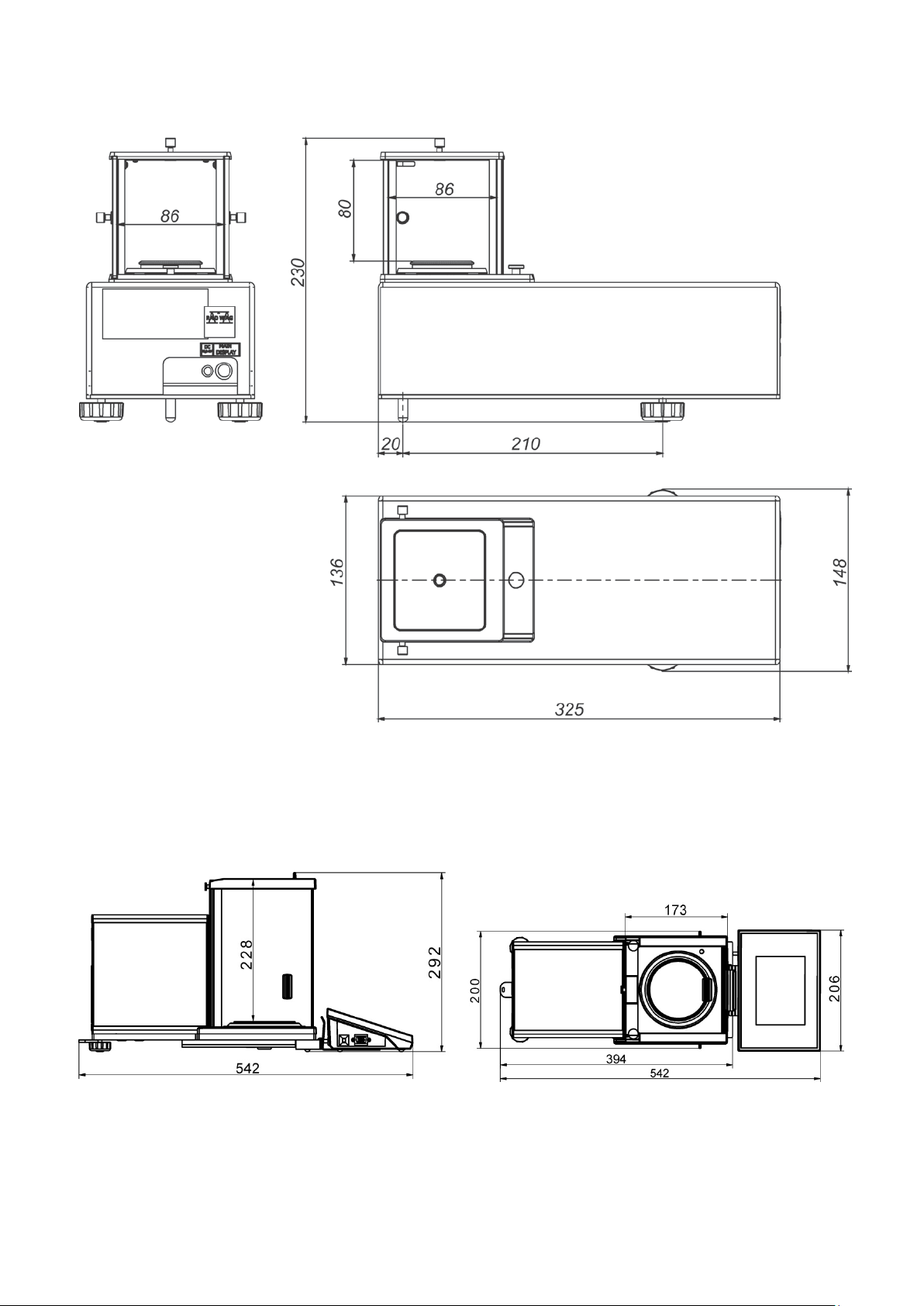
1. GENERAL INFORM ATION
1.1. DIMENSIONS
Ultra-microbalances and microbalances
- 9 -
Page 10
MYB 4Y Microbalances
Indicator
XA 4Y series balances
- 10 -
Page 11

XA 4Y.F series balances
- 11 -
Page 12

1.2. CONNECTORS
3 – USB connector
(RS232)
EPSON printer)
IN/OUT cable
(RS232)
1 –Ethernet RJ45 connector
4 – IN/OUT, RS232 connector (COM2)
2 – RS232 connector (COM1)
CAUTION!
“Balance-Ethernet” cable is a standard cable terminated with RJ45 connector on both ends.
Balance – computer
cable
Balance – printer
cable (CITIZEN,
1.3. INTENDED USE
4Y series balances are intended for precise mass measurement under laboratory conditions.
1.4. PRECAUTIONS
• Prior the first use, it is highly recommended to carefully read this User Manual, and operate the
balance as intended.
• Do not operate the touch panel using sharp-edged tools (knife, screwdriver, etc.).
Balance – computer
cable
- 12 -
Page 13

• While loading the balance make sure that loads are placed in the very center of the weighing
pan.
• Load the weighing pan with loads, gross weight of which does not exceed instrument’s
measuring range (maximum capacity).
• Do not leave heavy loads on the weighing pan for a longer period of time.
• In case of failure, immediately unplug the instrument from the mains.
• Balances to be decommissioned, have t o be decommissioned in accordance with valid legal
regulations.
• Do not use the balance is areas endangered with explosion. The 4Y series is not designed to
operate in EX zones.
1.5. WARRANTY CONDITIONS
A. RADWAG feels obliged to repair or exchange all elements that appear to be faulty by
production or by construction,
B. Defining defects of unclear origin and means of their elimination can only be realized with
assistance of manufacturer and user representatives,
C. RADWAG does not bear any responsibility for defects or losses resulting from unauthorized or
inadequate performing of production or service processes,
D. Warranty does not cover:
• mechanical defects caused by product exploitation other than intended, defects of thermal
and chemical origin, defects caused by lightning, overvoltage in the power network or
other random event,
• balance defects if it is utilized contrary to its intended use,
• balance defects, if service claims removing or destroying protective stickers which secure
the balance’s housing against unauthorized access,
• mechanical defects or defects caused by liquids and natural wear,
• balance defects caused by inappropriate setting or by electrical wiring failures,
• defects caused by overloading the mechanical measuring system,
• maintenance activities (cleaning).
E. Loss of warranty takes place if:
• a repair is carried out outside RADWAG sales office or authorized service point,
• service claims intrusion into mechanical or electronic construction by unauthorized people,
• other version of the operating system is installed in a balance,
• the balance does not bear company protective stickers.
F. Det ailed warranty conditions are listed on a service card.
1.6. METROLOGI CAL PARAMETERS MONITORING
Metrological characteristics of the balance require periodical inspection to be carried out by its user.
Inspection frequency is dependent on ambient conditions in which the balance is used, types of
performed processes and accepted quality management system in organization.
1.7. USER MANUAL SIGNI FI CANCE
It is very important to read the user manual carefully before switching on and starting up balance
operation, even if you are experienced and have worked with this type of balance before.
1.8. BALANCE USER TRAINING
The balance has to be utilized and supervised only by users who are trained and experienced in
using such type of weighing instruments.
- 13 -
Page 14

2. TRANSPORT AND STORAGE
2.1. DELIVERY CHECKLIST
Upon delivery it is necessary to check the package and the device, make sure that your package
bears no signs of damage. If it does contact the manufacturer’s representative.
2.2. PACKAGE
Keep all package elements should your balance be transported in the future. Remember that only
original packaging can be used for shipping purposes. Prior packing uncouple any cables, remove
any separable components (weighing pan, shields, inserts). Pack the device components into an
original packaging. The original packaging protects the equipment against potential damage during
transportation.
3. UNPACKING AND INSTALLATION
3.1. PLACE OF USE AND ASSEMBLING
• The balance has to be stored and used in locations free of vibrations and shakes, free of air
movement and dust.
• Ambient air temperature cannot exceed the range of: +10 °C ÷ +40 °C.
• Ambient relative humidity cannot exceed 80%.
• During balance operation, ambient temperature in the weighing room cannot change rapidly.
• The balance has to be located on a stable wall console desk or a stable working table which is
not affected by vibrations and distant from heat sources.
• Take special precaution when weighing magnetic objects, as part of the balance is a strong
magnet. Should such loads be weighed, use under-pan weighing option, which removes the
weighed load from area influenced by the balance’s magnet. The hook for under-pan weighing
is installed in balance’s base.
3.2. UNPACKING
Cut the adhesive tape. Take the device out of the packaging. Open the accessory box, take the
device components out of it.
3.3. STANDARD DELIVERY COM PONENTS LIST
• Balance
• Bottom insert (XA)
• Centring ring (XA)
• Bottom ring (UYA, MYA)
• Lid for weighing pan (UYA, MYA)
• Weighing pan
• Anti-draft chamber
• Bottom ring
• Power supplier
• User Manual – CD version
- 14 -
Page 15

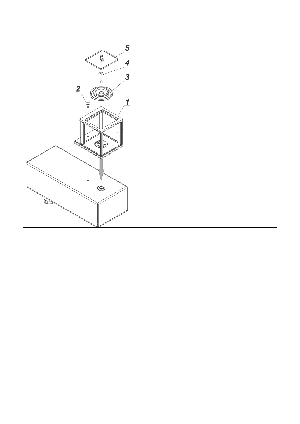
Install components following the above diagram depending on balance’s type.
A – standard (UYA and MYA)
B – MYA 0.8/3.4Y microbalances
Balances are equipped with standard weighing
C – balance for filters
D – pipettes calibration balance
4. Glass lid for the weighing pan
Pipette calibration:
indication is stable press TARE button.
CAUTION: Make sure there is no protective sticker 1 while carrying measurement (see the above
diagram).
2. Anti-draft chamber
3. Weighing pan
4. Glass lid for the weighing pan
12. Bottom ring
10. Weighing pan for filters
11. Standard weighing pan
pan (A) and weighing pan for filters.
12. Bottom ring
9. Weighing pan for filters
4. Glass lid for the weighing pan
2. Anti-draft chamber
3. Weighing pan
5. Glass vessel
6. Evaporation ring
7. Glass lid for the weighing pan, with a n
opening
8. Additional glass lid
On balance activation replace the weighing pan with weighing pan with glass vessel (5). W hen the
- 15 -
Page 16
MYB 4Y Microbalances
gently press
the transport lock and turn it accordingly to
should your balance be transported in the
ts following the above
centring ring [embossment side up]
Take all the components from the packaging.
Install the anti-draft chamber (1) and screw it to the base
using bolt (2).
Install:
- Draft shield (3)
- Weighing pan (4)
- Glass lid (5)
A – balance with d=0.01mg interval
B – balance with d=0.1mg interval
Remove a transport lock (9) –
<OPEN> instruction, keep the transport lock
future.
Install componen
diagram:
• bottom insert (5),
•
(4),
• weighing pan (2),
• anti-draft chamber (3) or (1).
Pipettes calibration balance
Replace the anti-draft chamber with pipettes
calibration chamber and install the pan and
other elements inside the chamber (see
description below).
- 16 -
Page 17

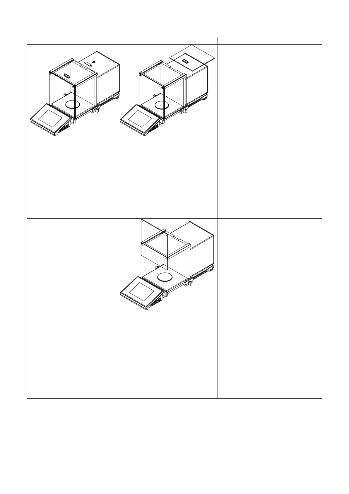
XA 4Y.F
open the weighing
Install all standard components:
• bottom insert (4)
• bottom ring (3)
• standard weighing pan (1)
• anti-draft chamber (2)
Install supplementary equipment.
Connect the balance to the mains (use the
power adapter provided by the manufacturer)
Before weighing filters remove the anti-draft
chamber (2), the standard weighing pan (1) and
the bottom ring (3). Next
chamber, and place a glass shield (6) and
assembly a pan-stand (5), intended for
weighing filters, inside.
Tare balance indication. Start weighing.
Caution:
To keep balance mechanism undamaged all operations must be done carefully and gently.
3.4. MAIN TE N ANCE ACTI VI TI ES
CAUTION!
Cleaning anti-draft chamber while still installed may cause damage of the measuring system.
1. Disassembly a weighing pan and other detachable components (the components differ
depending on a balance type – see Unpacking and Installation section). Be careful while
detaching the components so as not to cause any damages to the balance mechanism. It is
recommended to use tweezers while detaching microbalance’s pan.
2. Using handheld vacuum cleaner remove dust from the weighing chamber (recommended
especially for microbalances).
3. You can disassembly anti-draft chamber panes of XA and AS series is order to clean them
properly – for disassembly instruction read below.
Cleaning anti-draft chamber panes:
Select dissolvent depending on a dirt. Never soak the glass panes in alkaline solutions since they
interact with glass and may cause damage. Do not use abrasive substances.
For organic dirt use acetone first, next use water or detergent. For other than organic dirt use diluted
acid solutions (soluble salts of hydrochloric or nitric acid) or base solutions (ammonium or sodium
base).
To remove ACIDS use protofilic solvent (sodium carbonate), to remove BASE use protogenic solvent
(mineral acid of various concentration).
In case of heavy contamination use brush or detergent nevertheless avoid detergents containing
large and hard molecules which could potentially scratch glass panes.
Use soft brush with wooden or plastic handle exclusively to avaoid risk of s cratches. Do not use wire
brush.
At the end of the cleaning process rinse the pane using running water first, distilled ne xt .
- 17 -
Page 18

Rinsing is a necessary cleaning process stage allowing to remove remaining soap, detergents and
other cleansers from the panes prior their reinstallation.
Avoid drying the panes either using paper towel or forced air circulat ion since some fibres, grains or
contamination of other type could permeate into the panes thus causing weighing errors.
One shall not use driers when drying measuring glass tools.
It is a frequent treatment to leave glass components on a rack to dry.
Cleaning powder-coated components:
For preliminary cleaning stage you need running water or wet sponge featuring large w holes, this w ill
help you to remove loose, heavy dirt.
Do not use cleansers containning abrasive substances.
Next using cloth and cleanser-water solution (soap, dishwashing liquid) gently rub the cleaned
surface.
Avoid using cleanser without water since it may result with damage of the cleaned surface, please
mind that large amount of water mixed with cleanser is a must.
Cleaning aluminium components:
While cleaning aluminium components use products acid by nature, e.g. spirit vinegar, lemon. Do not
use abrasive substances. Avoid using hard brush, this may cause scratches. It is recommended to
use microfibre cloth.
While polishing the surface use circular movements. Use clean, dry cloth
.
Cleaning stainless steel components:
Avoid using cleansers containing any corrosive chemicals, e.g. bleach (containing chlorine). Do not
use abrasive substances. Always remove the dirt using microfiber cloth to avoid damage of protective
coating.
In case of a daily maintenance:
1. Remove the dirt using cloth dipped in warm water.
2. For best results, add a little dishwashing detergent.
Cleaning ABS components:
To clean dry surfaces and avoid smutching use clean non-colouring cloths made of cellulose or
cotton. You can use a solution of water and detergent (soap, dishwashing detergent, glass cleaner).
Gently rub the cleaned surface and let it dry. Repeat cleaning process if needed.
In the case when contamination is hard to remove, e.g. adhesive, rubber, resin, polyurethane foam
residues etc., you can use a special cleaning agents based on a mixture of aliphatic hydrocarbons
that do not dissolve plastics. Before using the cleanser f or all surfaces we recommend carrying out
tests. Do not use products containing abrasive substances.
- 18 -
Page 19
XA 4Y.A series – order of actions:
Undo and remove top pane
Remove the left and the right side
it must be remembered which is
procedure completion the panes
must be installed on the correct
Undo the screws protecting the
Remove the weighing pan and the
to damage the mechanism while
protection, next slide the pane out
of a guide bar.
pane. Before removing the panes
completely pull protection, see the
picture on the left. The side panes
are not interchangeable therefore
left, which is right. Upon cleaning
side.
front pane, next remove it.
pan’s anti-draft chamber so as not
carrying out the cleaning process.
- 19 -
Page 20

XA 4Y series – order of actions:
Undo and remove top pane
protection, next slide the pane out
Remove the back pane.
Remove side panes.
Side panes shall not be swapped
therefore it is necessary to
remember which one is right, and
CAUTION! Do not remove the front
Remove a weighing pan, a anti-
, a bottom insert.
Clean the components when
detached. With this your balance
mechanism is protected against
of a guide bar.
which one is left in order to install
them back properly.
pane!
draft chamber
accidental damage.
- 20 -
Page 21

Thus prepared anti-draft chamber and panes can be properly cleaned. All the operations have t o be
done carefully. Pay special attention t o the spot where the weighing pan is installed: dirt and other
small elements might enter the balance construction through this opening, which might negatively
influence the balance parameters.
Upon completion of the cleaning process assembly the balance, take actions like before but in a
reverse order. Pay a special attention to the left and the right side pane, assembly it on the correct
side of the balance. While sliding the pane back onto its place remember to pull the protection (like
before when dismantling the anti-draft chamber).
3.5. POWERING THE DEVICE
The balance has to be plugged to the mains using the original power adapter exclusively. Nominal
power supply of the power adapter (specified on t he power adapter data plate) has to be compat ible
to the power from the mains. Plug the power adapter’s to the power supply socket located at the back
of the housing.
3.6. TEMPERATURE STABILIZATION
Before measurement it is necessary to wait until the balance reaches thermal stabilisation.
For balances that were stored in much lower temperatures before plugging to the mains, thermal
stabilisation period shall take at least 12 hours. During the thermal stabilization, t he indications on a
display panel can change. It is recommended that ambient temperature changes at place of use were
insignificant (slow to change).
3.7. CONNECTING PERI PHERAL EQUIPMENT
Use only accessories and peripheral equipment recommended by the manufacturer. The balance
must be unplugged before connecting or disconnecting any peripherals (printer, PC computer,
computer keyboard). On connecting the peripherals, plug the balance to the mains.
3.8. B ALANCES FEATURI NG TERMINAL-WEIGHING MODULE WIR ELESS CONNECTION
(an option)
The terminal operates on batteries, wireless connection ensures its cooperation with the weighing
module. This, in contrast to a standard design, allows to eliminate cable connecting the devices.
Wireless connection solution is marked by letter <B>, e.g. XA 220.4Y.B.
Features:
Maximum range: 10 m
Maximum operation time of the terminal (without the necessity to charge batteries): 8 h
Advantages:
1. Lack of additional sources of vibration
Terminal located elsewhere than the weighing table eliminates vibrations being a result of
operation. This ensures stable working conditions for balances with the highest resolution. No
specific weighing workstations are needed.
2. Comfort of weighing in fume cupboards and laminar flow cabinets
- 21 -
Page 22

Wireless connection between a terminal and a weighing module positively influences
No.
Pictogram
Description
weighing process making it m ore comfortab le and safer.
3. Elimination of unfavourable influence factors
Due to wireless connection the weighing module may be completely separated from the
operator by being placed in an anti-draft chamber. This makes weighing of contaminated and
toxic substances possible without putting one’s health and life to risk.
4. Improved pipetting ergonomics
Pipettes calibration process requires precision and quickness of operation. Wireless
connection redefines comfort of operation and guarantees high measurement accuracy.
Wireless solutions are equipped with 2 power suppliers. One used for supplying the weighing
module, the other for powering the terminal.
3.8.1. Start-up Procedure
On unpacking and placing the balance onto its workstation it is necessary to connect the weighing
module and the terminal to the mains. Next proceed like in case of a standard design (description to
be found further down this user manual).
Home screen for wireless connection solution:
Home screen for wireless connection solution features two extra pictograms when compared to a
standard design:
1. battery charge status pictogram
2. wireless connection pictogram
Operation and functions are identical like for standard design balances.
3.8.2. Pictograms Description
Battery charge status pictogram:
1
2
3
4
5
Battery charging
Battery charged, terminal connected to the mains
Battery charged, terminal not connected to the mains
Battery status (about 50%), terminal not connected to the mains
Low battery status, necessity of connecting the terminal to the mains
- 22 -
Page 23

Wireless connection pictogram:
No.
Pictogram
Description
Key
Description
Press to enter the main menu of a
1
2
3.8.3. Settings
In order to provide long enough operation while powering the device by means of battery, the correct
parameters of group MISCELLANEOUS must be set, <Sleep mode> <Display brightness>. For
detailed information go to section 34 of this user manual: Miscellaneous.
Correct connection of wireless modules – correct cooperation
Connection interrupted – loss of connection
4. START-UP
1. On plugging the balance to the mains, instrument’s diode ON/LOAD
located on indicator’s housing is lit up.
2. Press
RADWAG software start loading, it is signaled by flickering red diode ON/LOAD.
3. On completing the startup procedure, the main window of the balance software is displayed.
4. The balance starts up with no user logged in. In order to start operation it is neces sar y to log in.
(logging procedure description to be found further down this user manual).
CAUTION! Remember to start the balance when unloaded.
power key located on the left. Within a few seconds the OS Windows and
5. KEYBOARD – BUTTONS’ FUNCTIONS
Press to switch the balance ON/OFF
Press to Zero the balance
Press to Tare the balance
Press to send measurement to a printer
or a computer
balance
Press to select working mode
Press to select user profile
Press to trigger an internal adjustment
- 23 -
Page 24
6. SOFTWARE STRUCTURE
ADJUSTMENT
USERS
PROFILES
DATABASES
COMMUNICATION
PERIPHERALS
INPUTS/OUTPUTS
ACCESS LEVEL
MISCELLANEOUS
UPDATE
INFORMATION ON
SYSTEM
MOVIES
The main menu has been divided into function groups. Each group comprises paramet ers grouped
by their reference. For detailed description of each menu group read later sections of this user
manual.
List of groups - Parameters
Balance’s main menu is accessed by pressing SETUP function key or
button located in the
bottom tool bar of balance’s display. The menu comprises parameters referring to balance settings,
functions and profiles.
- 24 -
Page 25

7. WEIGHING MODE HOME SCREEN
The main window of balance software can be divided into 4 sections:
• Top section displaying data on active working mode, logged operator, date, time, active
connection to a computer and current level status of a balance.
• Section presenting the weighing result and a current measuring unit.
• Grey workspace containing additional data on currently carried out activities.
CAUTION!
Data contained in the workspace is freely configurable. For detailed information on data configuration
refer to section 14.4 of this user manual.
• Workspace with set of soft keys:
CAUTION!
You c an define the on-screen function butto ns. For detailed instr uction go to section 14. 3 of this user
manual.
- 25 -
Page 26

8. LOGGING
or
Full access to user parameters and to editing databases requires logging as an operator with
<Administrator> permissions level. Carry out logging procedure on each switching on of the
balance.
First Log In operation - procedure:
1. Run home screen and press <Log in> button, operators database window opens with list of
available users and <
2. Select <
operator’s password: „1111”.
3. Press
4. Home screen of the software is displayed again automatically, <Log in> sign is replaced with
<Admin> sign.
5. When logged, add users and set the permissions levels (for the procedure of assigning
permissions levels read section 11 and 12).
On future Logging In, select a user from the list and enter the password, the software initiates
operation with permissions level set for the selected user.
Log out operation – procedure:
1. Run home screen and press logged user name, operators database window opens.
2. Press <Log out> button (position no. 1 of th e l ist of o perators).
3. Home screen of the software is displayed again automatically, <Admin> sign is replaced with
<Log in> sign.
Admin> parameter, the software activates an on-screen keyboard, use it to enter
button to confirm.
Admin> entry.
9. OPERATING BALANCE MENU
Operation of balance software menu is intuitive and uncomplicated. The touch panel makes the
software operation easy. Pressing a function key, a soft key or an area on the display initiates an
assigned function or process.
9.1. SOFT KEYS LIST
Press to enter the main menu.
Press to scroll the menu „up”.
Press to scroll the menu „down”.
Press to scroll the menu „up-down” fast.
Press to confirm changes.
Press to resign form introducing function modifications.
Press to add a new record to a database.
Press to search for a particular record in a database by date.
- 26 -
Page 27

Press to search for a particular record in a database by name.
Press to read printout template from a file format *.lb (f unction key is
active on inserting a USB flash drive to terminal’s USB port)
Press to search for a particular record in a database by code.
Press to print out a particular record from a database.
Press to clear the editing field.
Press to enable / disable an on-screen keyboard.
Press to select variables for a printout from a list.
Press to move (exit) one level up.
9.2. RETURN TO WEIG HING MODE
Introduced modifications are automatically saved to menu on return to the weighing mode.
Procedure:
1. Press
soft key repeatedly, keep pressing the key until the balance home screen is
displayed.
2. Press
soft key located on the balance overlay for immediate display of a home screen.
10. ADJUSTMENT
4Y series balances feature automatic internal adjustment system which ensures correct
measurement accuracy. Menu <ADJUSTMENT> contains functions controlling operation of balance
adjustment process.
10.1. INTERNAL ADJUSTMENT
Internal adjustment is carried out by means of an internal adjustment weight. <Int ernal adjustment>
button, when pressed, automatically triggers adjustment process. Upon adjustment process
completion respective message, informing about process end and about its status, is displayed.
CAUTION!
Adjustment procedure requires stable environmental conditions (no air drafts or ground vibrations). The
process must be carried out with an empty weighing pan.
10.2. EXTERNAL ADJUSTMENT
External adjustment is carried out by means of an external mass standard of specified accuracy class
and weight. Both, accuracy class and mass standard weight depend on balance type and max
capacity. The process takes semi-automatic form, successive stages are signalled with prompts.
CAUTION!
External adjustment is possible for balances that are not a subject to conformity assessment (verification).
- 27 -
Page 28

Procedure:
1. Enter <Adjustment> submenu, next select “
External adjustment” parameter.
2. “Remove weight” prompt is displayed.
3. Take the weight off the weighing pan and press
button. Whereas balance determines
start mass, “Start mass determination” message is displayed.
4. Upon completed start mass determination procedure “Put weight …” prompt is displayed along
with particular mass standard value.
5. Put the required weigh on a pan and press
button.
6. Upon completed procedure “Remove weight” prompt is displayed.
7. Take the weight off the weighing pan, press
button, the balance proceeds to the
weighing mode.
10.3. USER ADJUSTMENT
User adjustment is carried out with an optional standard of mass ranging between 0.15 Max and
Max. User adjustment and external adjustment procedures are likewise with one exception, bef ore
user adjustment start a message box for entering mass of a standard used for user adjustment is
opened.
CAUTION!
User adjustment is possible for balances that are not a subject to conformity assessment (verification).
In order to start user adjustment, enter <Adjustment> submenu and select ‘
User adjustment’
parameter. Then follow the prompts displayed on a screen.
10.4. ADJUS TM E NT TE S T
<Adjustment test> function enables comparing the result of an internal automatic adjustment with the
value recorded in balance factory parameters. The comparison is used for determining balance
sensitivity drift over tim e.
10.5. AUTOMATIC ADJUSTMENT
This menu is for declaring a value initiating an automatic adjustment. Accessible options:
• None – automatic adjustment disabled,
• Time – adjustment takes place in time intervals declared in menu <Automatic adjustment time>
(10.6),
• Temperature – adjustment is triggered by temperature change only,
• Both – adjustment is triggered by both, temperature changes and time.
CAUTION!
Parameter settings can be modified only for balances that are not a subject to conformity assessment
(verification).
10.6. AUTOMATIC ADJUSTMENT TIME
<
Automatic adjustment time> parameter determines time interval between successive internal
adjustments carried out automatically. The time interval is declared in hours and ranges between 1
and 12 hours.
To set time interval for automatic adjustment:
• select <Automatic adjustment time> parameter,
- 28 -
Page 29

• using displayed menu, select appropriate time interval (given in hours) which is a time gap
Enter user menu, select <Adjustment> parameter
Enter <Scheduled adjustments> parameter, wait for
’ window to open, add
elapsing from the last carried out int ernal automatic adjustment until activation of the f ollowing
automatic internal adjustment.
CAUTION!
Parameter settings can be modified only for balances that are not a subject to conformity assessment
(verification).
10.7. SCHEDULED BALANCE ADJU STMEN T
<
Scheduled adjustments> parameter allows you to specify precisely time for adjustment
performance and interval between successive adjustments. The parameter is independent from
automatic adjustment and criteria that trigger it (time, temperature). You can plan when internal and
external adjustment shall be performed. In order to design schedule for external adjustment, it is
necessary to record into balance memory mass standards for adjustment performance.
Parameter values:
1. Enter data of mass standards intended for external adjustment performance.
2. Enter user menu, select <Adjustment> parameter group and find <
parameter, enter necessary data:
group and find <Scheduled adjustments> parameter.
Mass standards>
‘Scheduled adjustments
adjustment procedures. Remember, only Administrator
can add new positions.
- 29 -
Page 30

In order to add a new position, click button, wait for
Select task: automatic adjustment (internal) or external
For automatic adjustment option, enter data on the
For external calibration option, enter data on the
When all necessary data has been introduced, go back
to the previous window. The window features newly
a window with data on planned balance adjustment to
open.
calibration.
adjustment and its schedule.
calibration, mass standard used for the calibration
performance and its schedule.
added position relating to planned balance adjustment
procedure.
Upon entering all data exit the menu.
Now all the adjustments are carried out automatically as planned and with specified time intervals.
- 30 -
Page 31

10.8. REPORT PRINTOUT
Parameter <
Report printout > determines whether or not a report on automatic internal
adjustment is to be automatically printed on its completion.
In order to set automatic report printout on adjustment completion go to parameter:
<
Report printout > and select value <YES>.
10.9. GLP PROJECT
GLP is one of many methods for documenting work in accordance with adopted quality system. Data
selected for printing is printed on each release of a report on balance adjustment.
Information a nd signs to be used in a GLP report:
• adjustment (adjustment mode)
• working mode (working mode name)
• date, time,
• user,
• balance type,
• balance ID,
• level status,
• nominal mass,
• current mass
• difference
• temperature,
• blank line,
• dashes,
• signature,
• non-standard printout.
10.10. ADJUS TMENT HISTORY
Adjustment history contains data on all carried out adjustment processes. The record is carried out
automatically. Each entry on adjustment comprises basic data on completed process. Balance menu
enables displaying the list of completed adjustment processes, and each report is printable.
In order to print a report on adjustment process, enter <Adjustment> submenu, next enter
<Adjustment history>, select adjustment to be printed. On displaying details of a record, press <
>
print key on display’s top bar.
CAUTION!
If the balance memory is full then the oldest record gets automatically deleted.
If internal procedures of an organization require maintaining complet e documentation from all carried
out adjustment processes, then the list with records on adjustment has to be periodically printed and
filed.
Searching for adjustment record
Balance enables searching for a specific record from completed adjustment processes:
– Press
search icon and insert date of adjustment process.
Exporting data on completed adjustment process
Connect a USB flash drive to balance’s USB port. Press < Data export> button located in the top right
corner of balance’s display. The process is fully automatic, and on its completion, a file with
- 31 -
Page 32

extension *.tdb is saved on a USB flash drive connected to the USB port. The file can be edited using
Excel spreadsheet or a text editor.
11. USERS
“Users” menu contains list of operators, who are authorized to operate the instrument.
The following data can be defined for each balance user:
Name
Code
Password
Access level
Language
Profile
Card no.
New user can be added by the Administrator exclusively.
Procedure:
1. Enter Users menu, press <Add>
2. Define all necessary fields.
CAUTION!
It is posible to search for a user in a database of users by code or name.
Edit data on a user:
Procedure:
1. Press field with name of a user.
2. The display indicates data on a specific user.
3. Select and change necessary data.
New user can be deleted by the Administrator exclusively.
Procedure:
1. Press and hold user name.
2. Menu referring to a user record is displayed.
3. Select <Delete> parameter.
key.
12. PERMISSIONS LEVELS
Access levels specify which operations are enabled/disabled f or a particular user. T his menu can
be modified by the Administrator exclusively.
Anonymous user
The Administrator can grant access level to a balance user who is not logged in (Anonymous user).
Procedure:
1. Enter <
Access level> menu.
- 32 -
Page 33

2. Select <
Anonymous user> parameter.
3. Set appropriate access level for the anonymous user. Available access levels for an
anonymous user: Guest, User, Advanced User, Administrator.
CAUTION!
Selecting <Guest> access level for not logged in user prevents him/her from modifying any balance settings.
Date and time
Default settings enable a user logged as the Administrator to modify date and time settings. The
software enables changing access level for <
Date and time> parameter.
Procedure:
1. Enter <
2. Select <
Access level> menu.
Date and time> parameter.
3. Set desired access level required to modify the settings. Available access levels for
changing date and time settings are: Guest, User, Advanced User, Admi nistrator.
CAUTION!
Selecting <Guest> access level provides free access to date and time settings (no need to log in).
Printouts
Default settings enable a user logged as the Administrator to edit default printout templates. The
software enables changing access level for <
Printouts> parameter.
Procedure:
1. Enter <
2. Select <
Access level> menu.
Printouts> parameter and select one of available parameters: Guest, User,
Advanced User, Administrator.
CAUTION!
Selecting <Guest> access level provides free access to printouts settings (no need to log in).
Printout/Value Release
Default settings enable a user logged as the User to edit default printout templates. The software
enables changing access level for <
Value Release> parameter.
Procedure:
1. Enter <
2. Select <
Access level> menu.
Value Release> parameter and select one of available parameters: Guest,
User, Advanced User, Administrator.
CAUTION!
Selecting <Guest> access level provides free access to printouts settings (no need to log in).
Movies
Default settings allow <Movies> menu to be accessed by the Administrator exclusively, as a result it
is only the Administrator who can perform adding or deleting operations. Providing that respective
modifications have been introduced by the Administrator, it is possible for remaining users to access
<
Movies> menu options too.
Procedure:
- 33 -
Page 34

1. Enter <
Access level> menu.
2. Select <
Movies> parameter, select one of available parameters: Guest, User,
Advanced User, Administrator.
CAUTION!
Selecting <Guest> access level provides free access to movies settings (no need to log in).
Auto logout
Auto logout parameter has been designed to trigger logout operation when the balance st ays inact ive
for specified time interval given in minutes. By default the parameter is set to <None> parameter.
Procedure:
1. Enter <
2. Select <
Access level> menu.
Auto logout> parameter, select one of available parameters: None/3/5/15/30/60.
Time given in [min].
Databases
The Administrator is authorized to set appropriate access level required in order to enable
modification of databases.
Procedure:
1. Enter <
Access level> menu.
2. Select <
Databases> parameter, set required access level: Guest, User, Advanced User,
Administrator for each of the databases.
CAUTION!
Selecting <Guest> access level provides free access to databases editing.
13. PROFILES
A Profile is a data pack determining:
• functioning of working modes, e.g. parts counting, percent weighing, etc.,
• data to be displayed during working mode operation,
• function keys to be active,
• measuring units to be accessible
• c r it er ia determining speed of operation and measurement stability,
Balance software allows you to create numerous profiles, this enables:
• eac h balance user to design an individual working environment
• customized balance operation, enabling/activating selected function keys and information
(improving ergonomics of operation)
13.1. CREATING A PROFILE
A default profile is named <Home>. The Administrator can create new profiles by:
• Copying an already existing profile, modifying it,
• Cr eat ing a new profile.
Copying an existing profile
Procedure:
- 34 -
Page 35

1. Enter main menu, to do it press Setup key.
Settings
Enter this menu to set an individual profile name (a order of alphanumeric
activated as default on profile selecting).
Working modes
Contains the following submenu:
Printouts
Readout
Contains the following submenu:
Last digit
Units
Enter this menu to declare the start unit, the supplementary unit, 2 custom
operation place.
2. Enter < Profiles> submenu.
3. Press and hold profile that is to be copied.
4. Menu referring to a profile record is displayed.
5. Select <Copy> parameter.
6. A new <Copy name> profile is created, all new profile setting and base profile settings are
likewise.
7. Modify necessary data: (name, etc.).
Adding a new profile
Procedure:
1. Enter main menu, to do it press Setup key.
2. Enter < Profiles> submenu.
3. Press
4. Press
key, message box: <Create new record?> is displayed.
key to confirm. The software automatically adds a new record and enters its
editing mode.
Deleting a profile
Procedure:
1. Enter main menu, to do it press Setup key.
2. Enter < Profiles> submenu.
3. Press and hold profile that is to be deleted.
4. Menu referring to a profile record is displayed.
5. Select <Delete> parameter.
6. Message box: <Confirm to delete> is displayed.
7. Press
key to c onfirm, the profile gets deleted.
CAUTION!
In order to operate profiles it is necessary to log in as an Administrator.
13.2. PROFILE STRUCTURE
Each profile contains the following entries:
characters), and to declaring a default working mode (the selected mode is
• Addit ional setting of a working mode
• Function keys
• Displayed information
•
• Filter
• Value r elease
• Autozero
• Aut ozero: Dosing
•
units and to enter the value of gravitational acceleration force in balance’s
- 35 -
Page 36

13.2.1. Settings
On entering this option, the display opens a message box with keyboard.
FILTER
ready to read.
You can determine signal processing extend, there are five different filters f or
or fast filter, in case of rough
Name
Insert name of a profile and press key to confirm.
The name is assigned to the profile.
Default working mode
On entering this opt ion you can select a specific working mode, which is set
as default in a profile. For <None> parameter set, upon selecting the profile,
the balance activates the most recently used working mode.
13.2.2. Working Modes
On entering Working Modes option, the display opens a window containing all accessible working
modes. Settings for each of the working modes can be customized, particular profile when activated
runs with given set of parameters.
List of parameters to be modified:
• Settings
contain specific parameters relating to a working mode and universal setting s, such as: result
control, tare mode, automatic footer printout, printout mode, printout.
• Functions of quick access keys
declaring quick access keys to be visible in the bottom display bar
• Information
declaring information to be displayed in the grey workspace
• Printout
declaring type of a printout or defining a non-standard printout
13.2.3. Readout
The function enables you to adjust balance operation to ambient conditions (filter settings) or your
individual needs. <Readout> menu contains the following elements:
Each measurement signal before being displayed is electronically processed in
order to provide cor rect parameters specific for stable measurement result, i.e.
you to select from:
• very fast
• fast
• average
• slow
• very slow
While setting the filter consider the actual operating conditions. I n case of very
good operating conditions select average
conditions select slow or very slow filter.
CAUTION!
For precision balances it is recommended to select very fast, fast or average filter.
For analytical balances and microbalances it is reco mmended to select average, slow,
very slow filter.
- 36 -
Page 37

Value release
The parameter has been designed to determine when the stability marker is to
be displayed.
There are three different settings for value release parameter:
Autozero function
and correction of zero indication.
If the function is enabled, the following measurement results are compared to
each other in constant time intervals. If the results differ less than declared
ocess. For instance during very slow load placing or pouring onto the
Autozero function: Dosing
dosing.
Accessible settings:
Last digit
place of measurement result.
Accessible settings:
Ambient conditions
than in case of setting to value Unstable.
• fast
• fast + reliable /recommended/
• reliable
CAUTION!
Both parameters, f ilter and value release, deter mine how long it takes to obtain stable
result.
The function has been designed to enable automatically carried out monitoring
AUTOZERO range, e.g. 1 division, the balance is automatically zeroed, and the
markers of stable indication
and precise zero are displayed.
Active AUTOZERO means, that each measurement starts from the precise zero
point. There are, however, cases where the function may disturb the weighing
pr
balance’s weighing pan. In such case, the correcting system of zero indication
may also correct the actual indication of a load placed on the weighing pan.
Accessible settings:
NO - autozero function disabled
YES - autozero function enabled
The function has been designed to set autozero to default value selected for
NO - aut ozero operation is automatically disabled on entering dosing mode
YES - autozero operation is automatically enabled on entering dosing mode
The function has been designed to enable/disable visibility of the last decimal
ALWAYS: al the digits visible
NEVER: last digit invisible
WHEN STABLE: last digit visible only for a stable measurement
The parameter refers to ambient conditions. By default it is set to value Stable.
For unstable ambient conditions it is advisable to set the parameter to value
Unstable.
Stable setting results with fast er operation, i.e. weighing takes much less time
Accessible settings
:
Unstable
Stable
13.2.4. Measuring Units
For a selected profile you can declare start unit, supplementary unit and two custom measuring units.
- 37 -
Page 38

Weighing
Parts counting
Means of operation: weight of a load is
form of measurement result.
Means of operation: based on a determined
Checkweighing
Dosing
Means of operation: control of sample mass
<HI>.
Means of operation: you have to specify
Percent Weighing
Density
Means of operation: control of percent ratio of a
sample).
Means of operation: based on Archimedes
Animal Weighing
Formulations
Means of operation: mass measurement takes
Means of operation: by adding a order of
ingredients and their mass.
Statistics
Pipettes calibration
Means of operation: carried out measurements
Min, Max, deviation, etc.
Means of operation: calibration of pipettes
according to user requirements.
A custom measuring unit features:
• A m u ltiplier
• A nam e (3 characters)
Upon completed operation of designing a custom unit its name is added to the list of accessible
measuring units.
Units menu additionally enables entering the value of gravitational acceleration force for balance’s
place of use. It is obligatory should a balance be used to determine mass in [N].
14. WORKING MODES
Standard 3Y series features the following working modes:
determined through an indirect measurement. A
balance measures gravitational force which
attracts the load. An obtained result is
processed to a digital format and displayed in a
with applied thresholds. You have to specify the
value of low threshold <LO> and high threshold
sample in relation to a standard mass
(reference weight). Obtained data provides
percent ratio on how test sample differs from
the accepted standard mass (reference
mass of a single part it is possible to count
another parts, assuming that mass of a single
part is determined with sufficient accuracy, and
that the following parts are equal in mass.
sample’s target mass to be obtained by pouring.
principle, a balance determines density of solids
and liquids. The mode requires an optional
density determination kit.
place with application of filters dampening
animal moves on a weighing pan, thus enabling
obtaining a correct measurement result.
are used to calculate statistical data, such as
ingredients, you can prepare an optional mixture
or formulation. Before mixing balance software
requires designing a formulation by specifying its
according to procedures listed in ISO 8655 or
- 38 -
Page 39

Differential Weighing
Statistical Quality Control
Means of operation: analysis of mass sample
Working mode is intended to carrying out
lack of product quantity in a packaging.
Peak Hold
Mass Control
Means of operation: freeze of max weight value
Working mode intended to carrying out quick
version)
Prepacked Goods Controls
Working mode intended for PGC processes in
version)
change over time.
different types of product packing processes and
aimed at monitoring and / or controlling the
packing process. It enables detecting excess or
on a display (max. indication reflecting the
greatest force exerted on a pan).
statistical control of samples in accordance with
the requirements on a quality system and/or
internal standards.
(mode not available in balance’s standard
accordance with the regulation on prepacked
goods.
(mode not available in balance’s standard
Worki ng mode setti ngs include special functions specific to a given mode. They enable customization
of particular mode’s operation. The special settings are activated on selecting a particular profile. For
detailed overview of particular mode’s special functions read section providing information on the
mode in question.
14.1. RUNNING WORKING MODE
To run a particular working mode:
1. Press active working mode name, it is displayed in the top left hand corner.
2. Wait for a list of available working modes to be displayed.
3. Select a particular working mode and press its name.
- 39 -
Page 40

14.2. PARAMETERS RELATED TO A WORKING MODE
You can define up to 7 quick access keys, which are
appears in the bottom navigation bar of
dedicated for most often used functions and
set of
buttons. For complete buttons list read Appendix B.
Each working mode has programmable parameters determining its functioning.
Procedure for entering the parameters:
1. Press gr ey workspace area
2. Wait to see the following menu:
− <Settings> - additional options
− <Keys> - defining quick access keys
− <Information> - selecting information to be displayed in the workspace
− <Printouts> - selecting printout type and content
− <Profile> - selecting a prof ile to be active in the course of operation
3. Enter particular submenu and select the component which is to be modified
For detailed information on parameters of <Settings> menu go to section 15.8 “Additional Parameters
for a Weighing Process”. For detailed overview of particular mode’s parameters read section
providing information on the mode in question.
14.3. QUICK ACCESS KEYS, PROXIMITY SENSORS
displayed in the bottom bar.
On assigning a function to a button a corresponding
pictogram
the main window. It is a so called quick access key,
processes.
Each working mode features customized
Caution:
You can view us er manual saved to balance me mory. In order to take advant age of this function help button
must be placed on a tool bar.
14.3.1. Proximit y Sensors
The balance features two proximity sensors enabling touch-free balance control.
The software detects four motions performed around the sensors:
1. hand in a close vicinity to the left sensor <Left sensor>,
2. hand in a close vicinity to the right sensor <Right sensor>,
3. Hand motion to the left <Proximity sensor: left motion>,
4. Hand motion to the right <Proximity sensor: right motion>.
- 40 -
Page 41

Automatically Opened Door submenu comprises settings on automatic opening and closing door
MYA 4Y series balance settings:
/ the option enables changing the position of the door, e.g. if the
ses opening the door of the weighing
XA 4Y.A series balance settings:
hanging the position of the door, e.g. if the
chamber is closed, then activating the option causes opening the door of the weighing
chamber.
Instruction on switching from manual to automatic door operation in XA 4Y.A series balance:
To return to manual operation, turn the knob to its previous position.
Information on weighing process is displayed in the grey
YES, information enabled (displayed in the
CAUTION!
Using LEFT MOTION or RIGHT MOTION, it is necessary to remember that <Proximity sensors delay>
parameter must be set to value 500 ms!
To each of the motions you can assign one of the available options: [None; Profile; Adjustment;
Zeroing; Taring; Tare setting; Tare switch off; Reset tare; Packaging; Print; Header printing; Footer
printing; Unit; Universal Variable 1; Universal Variable 2; Universal Variable 3; Universal Variable 4;
Universal Variable 5; Confirm; Abort; User; Left door; Right door; Open/Close door; Parameters;
Product, Warehouse; Customer].
The selected option is recognized by the software and performed when activated by a particular
motion.
In order to ensure correct operation it is necessary remember to set the right sensors sensitivity and
the right value for proximity sensors delay (for more information go to section 34 of this user manual).
14.3.2. Automatically Opened Door
of a balance featuring such mechanism, i.e. MYA 4Y and XA 4Y.A series balances. T he settings
may refer to the quick access keys as well as the infrared proximity sensors located on the
overlay of balance’s terminal.
• Left door – the option enables changing the position of the door to the left side of the
weighing chamber
• Ri ght door - the option enables changing the position of the door to the right sid e of the
weighing chamber
• Open / Close door
weighing chamber is opened, then activating the option causes closing it. If the weighing
chamber is closed, then activating the option cau
chamber.
• Open / the option enables opening the door of the weighing chamber
• Close / the option enables closing the door of the weighing chamber
• Open / Close door / the option enables c
weighing chamber is opened, then activating the option causes closing it. If the weighing
1. When operating in manual mode turn the door knob 180o eithe r left or r ight
2. Using your hands slide the door, both left and right, from the front to back thus making
them couple the mechanism.
Door coupling is easy to be sensed (the pawls get engaged with the notch).
14.4. INFORMATION
workspace. It can contain up to 6 data. If larger amount
of data is selected, then only the first 6 are displayed.
Each parameter features two options:
workspace).
- NO, information disabled.
- 41 -
Page 42

14.5. PRINTOUTS
Printouts menu comprises two separate sections:
Header
Weighing
Footer
Dashes
Universal variable 1
N (measurements
Current measurement
Supplementary weighing
• Non-standard printout
Working mode
Print header data
Print footer data
• standard printouts,
• non-standard printouts.
Standard printout
Standard printout comprises three internal sections featuring different variables. For each variable set
option YES to include it in a standard printout. If option NO is selected, then the variable is disabled,
i.e. it is not printed.
Procedure:
1. Press field with name of a template to be edited (Header – Weighing – Footer) and select
variables to be printed.
2. If a printout is a non-standard one, create it.
•
• Working mode
• Date
• Time
• Balance t ype
• Balance I D
• User
• Level stat us
• Customer
• Warehouse
• Product
• Packaging
•
… 5
• E m p ty line
• GLP report
• Non-standard printout
•
quantity)
• Date
• Time
• Level stat us
• Customer
• Warehouse
• Product
• Packaging
• Universal variable 1 … 5
• Net
• Tare
• Gross
•
result
•
unit
• Mass
•
• Date
• Time
• Balance t ype
• Balance I D
• User
• Level stat us
• Customer
• Warehouse
• Product
• Packaging
• Universal variable 1 … 5
• Dashes
• E m p ty line
• GLP report
• Signature
• Non-standard printout
BASIC PRINCIPLES RELATED TO PRI NTOUTS
1. In order to print WEIGHING section variables press PRINT button on balance’s overlay, only
variables with attribute YES can be printed (see the above list).
2. Variables with YES attribute present in the HEADER and FOOTER are printed ONLY on
pressing PRINT HEADER and PRINT FOOTER pictograms. The pictograms have to be added
to the bottom bar of the display, as quick access keys.
For detailed instruction on how to add quick access keys to the bottom bar of the display go to
section 14.3.
CAUTION!
Measuring units for mass indication:
• Net – main measuring unit (adjustment unit)
• Tare – main measuring unit (adjustment unit)
• Gross – main measuring unit (adjustment unit)
- 42 -
Page 43

• Current result – curr ently di s played me as ur ing unit
Verified
balance
Verified
balance
kilogram
[kg]
yes *
Taele Taiwan
[tlt]
no
• Supplementary unit – supplementary measuring unit
• Mass – main measuring unit (adjustment unit)
Non-standard printout
Non-standard printout may contain: TEXTS and VARIABLES (which are acquired from the software).
Each non-standard printout is a separate project, featuring specific name, by which it is identified,
and saved to the database of printouts.
Procedure:
1. Press <Non-standard printout> field.
2. Press <
Add> button, a window featuring Name/Code/Project data opens.
3. Set name and code of a printout.
4. Press <Project> button, a keyboard is opened on the display for editing the printout.
5. Use the keyboard to design printout template, the printout may contain texts and variables.
CAUTION!
It is possible to add a printout by importing configured texts from flash drives connected to balance’s USB port.
Printout’s name is ONLY a NAME, and it is not part of its content.
For information on how to design a non-standard printout template read section 30.19 <Printouts>.
14.6. PROFILES
Profiles function has been described in section 13 Profiles.
15. WEIGHING OPERATION
Load a weighed object on a balance weighing pan. On s tabilization of weighing result, indicated by
stability marker
Record / printout of the measurement result is available on pressing <PRINT> key:
• for verified balances – only stable measurement result can be saved or printed (stability marker
visible on balance’s display),
• for non-verified balances – stable or unstable measurement result can be saved or printed
(regardless of stability marker
<?> is printed next to the mass value.
visible on the left side of balance display, read the measurement result.
absence) . For unstable measurement result question mark
15.1. WEIGHING UNIT SELECTION
Change of weighing unit is carried out by pressing the weighing unit icon visible next to the value of
measurement result. Clicking the unit triggers display of available units lis t. Select the unit you need,
the software automatically recalculates indicated value.
Units list:
Unit Denotation
gram [g] yes Taele Hongkong [tlh] no
milligram [mg] yes * Taele Singapore [tls] no
carat [ct] yes * Taele China [tlc] no
pound [lb] no Momme [mom] no
ounce [oz] no Grain [gr] no
ounce Troy [ozt] no Newton [N] no
pennyweight [dwt] no Tical [ti] no
* - Accessibility of measuring units is conditioned by balance type. SI system units are accessible for nonverified balances
Unit Denotation
- 43 -
Page 44

15.2. GOOD WEIGHIN G PRACTICE
YES
NO
YES
NO
NO
NO
In order to ensure long lasting use of a balance plus correct and reliable measurement of weighed
loads, follow below procedures:
• Start the balance with no load on the weighing pan (permissible value of load on the weighing
pan on balance start is ±10% of its maximum capacity).
• Load the weighing pan steadily avoiding shocks:
• Place weighed loads centrally on the weighing pan:
• Avoid side loading, in particular side shocks:
15.3. BALANCE L EVELLING
The 4Y series features AutoLEVEL System, which continuously monitors level status during balance
operation. The level status is signaled in the top right hand corner of a display. The system
continuously controls level, and on detecting any change it indicates appropriate information on the
display and/or starts an alarm, as a result a window for adjusting the level is displayed.
Balance levelling procedure
1. Press level status pictogram <
> located in the top right hand corner of the display.
2. Control panel of leveling function is displayed, it features level status and balance’s top
elevation.
- 44 -
Page 45

3. Level the balance, to do it turn the feet in a way indicated by blinking pictograms on the display
> – the level point moves towards the center of the level circle.
<
4. As the level point is in the center point, its colour changes from red to green – which is a
confirmation for correct level status.
CAUTION!
The balance is equipped w ith Automatic Leve l Control mechanism. For detailed information go to sectio n 34.8
of this user manual.
15.4. BALANCE ZEROING
Zeroing is a function allowing to zero mass indication. In order to zero mass indication, press
button. Mass indication of zero value is displayed tog ether with precise zero
and stability
markers.
Zeroing process is an equivalent for determining new zero point, recognized by the balance as
precise zero. Zeroing is possible only for stable status of display indication.
CAUTION!
Zeroing the display indication is possible only within ±2% range of instrument’s maximum capacity. If the
zeroed value is ab ove ±2% of the max imumcapacity, th en the software ind icates a respective error message,
Err2.
15.5. BALANCE T AR ING
Taring is a function allowing to determine net weight of a measured object. In order to determine net
weight of the object, place object’s container (packaging) on the weighing pan, and on stabilization of
measurement result press
key. The display indicates mass equal zero and symbols: Net and
. On taking off the weighed load and its packaging from t he weighing pan, the display indicates
sum of total tared mass with minus sign.
The software enables assigning tare value to a database-stored product. Using this option, the
software automatically uploads data on tare value for a particular produc t upon its selection from the
database.
CAUTION!
Taring negative values is imposs ib le. On tar i ng ne gat i ve v alues the ba lance r esponds with an Err3 message. In
such case, zero balance indication and repeat taring procedure.
Manual tare determination
Procedure:
1. While in optional mode press
quick access key.
2. An on-screen numeric keyboard is displayed.
3. Enter tare value and press
key.
- 45 -
Page 46

4. The balance returns to the weighing mode, and the display indicates enter ed tare value with
The chart presents correction values for
Sample mass [g]
minus ‘–‘ sign.
Deleting tare
The tare value indicated on a balance display can be deleted by pressing
key on a balance
overlay, or by using programmable function key <Deactivate tare>.
PROCEDURE 1 – on taking the tared load off the weighing pan
1. Press
key.
2. The NET marker is deleted, and new zero point of the balance is determined.
PROCEDURE 2 – with tared load on the weighing pan
1. Press
key.
2. The NET marker is deleted, and new zero point of the balance is determined.
3. When tare value exceeds 2% of the maximum capacity, Err message is displayed in order to
inform you about the fact operation cannot be carried out.
PROCEDURE 3 – when the tared load is on the weighing pan or on taking the tared load off the
weighing pan
1. Press programmable key <Deactivate tare>
2. The NET marker is deleted.
3. The display indicates tare value.
4. Press <Restore tare>
key to restore the last tare value .
15.6. USE OF AIR BUOYANCY COMPENSATIO N FACTOR
The application enables correcting mass measurement errors in the course of:
1. weighing loads of density considerably different from the density of standard that has been
used to adjust the balance; typically the balance is adjusted with a steel mass standard with
density ~8.0g/cm3 or a brass mass standard with density ~8.7g/cm3; if loads made of other
substances are weighed, then ratio indicated on below chart applies.
Error value in relation to density of weighed sample
Correction value [mg]
mass in relation to the density of weighed
load, assumption that air density is
constant and equals 1.2 kg/m
Density of weighed load
3
is taken.
2. testing sample mass change within a few hours long period of time for a case when the sample
mass is relatively constant (minor changes); it is assumed that air density changes affect
- 46 -
Page 47

considerably the final result, wherein the density is influenced by changes of pressure,
temperature and humidity.
In order to carry out a reliable measurement it is necess ar y to know the measuring methods, features
of tested sample, air density in the laboratory room and density of weighed sample.
Functioning
The air buoyancy compensation procedure is to be used as follows:
1. Method 1:
Enter air density value and value of weighed sample density to balance’s memory. Wait, the
software automatically calculates the correction factor for weighed mass, next corrected value
of weighed mass is displayed. In order to avoid mistakes, the corrected mass value is
accompanied by <!> symbol, the symbol is visible on a display and a printout.
2. Method 2:
Determine air density value with use of balance software (semi-automatic operation) and enter
value of weighed sample density to balance’s memory.
Determination of air density is carried out using a set of two mass standards, one made of
stainless steel, and the other one of aluminum. Based on mass indications of the two
standards, the software automatically calculates the air density and saves the value in
balance’s memory on operator’s confirmation. Now, enter value of weighed sample density to
balance’s memory. Wait, the software automatically calculates the correction factor for weighed
mass, next corrected value of weighed mass is displayed. The corrected mass value is
accompanied by <!> symbol, the symbol is visible on a display and a printout.
In order to enable/disable the air buoyancy compensation procedure go to the user menu. The
procedure is valid for weighing mode exclusively.
Air Buoyancy Compensation Start-Up
Procedure:
1. Enter home screen and press grey workspace.
2. Select <Settings> parameter.
3. Select <
Air buoyancy compensation> parameter.
Parameter values:
• Air buoyancy compensation – YES/NO.
• Sample density (enter value of weighed sample density). If you use products from
databases, then on product selection its density value is automatically uploaded.
• Air density – parameter designed to enable selecting the method of entering the air
density value.
PARAMETER VALUES:
VALUE – select to open a window where you enter specified air density value (e.g.: determined by
means of other m ethods). The entered value is used in the course of compensation. It is assigned
automatically upon completed air density determination after <
> key has been pressed.
ONLINE – select to make the balance acquir e air density value from a connected THB sensor at a
real time, if such is connected to the balance, or from internal sensor installed in the balance.
If your balance features both types of sensors (THB module and internal sensor), t hen data from the
THB module supersedes the other, in such case go to Setup/Ambient Conditions/Ambient
Conditions Module and set SAVE or SAVE & ALERTS parameter.
If your balance features only one se t of sensors recording temperature, humidity and pressure, then
correct ONLINE operation requires setting the following parameters:
• int ernal sensors exclusively – go to Setup/Ambient Conditions/Ambient Conditions Module
and set NONE value,
• external THB module exclusively – go to Setup/Ambient Conditions/Ambient Conditions
Module and set SAVE or SAVE & ALERTS value.
- 47 -
Page 48

For correct balance cooperation with the THB module it is necessary to set port’s transmission
parameters, they must be com patible with those of the T HB module. The THB module transmission
parameters are detailed on its data plate.
On returning to the weighing mode, the display indicates an additional symbol <
!>, as indicated on
the figure below. From now on the value of indicated mass is corrected including the air buoyancy
compensation factor and sample density.
The measurement result can only be compensated by a correct value if the operator enters the actual
value of the air density and correct value of weighed sample density to balance’s memory.
CAUTION!
If the <AIR BUOYAN CY COMPENSATION > parameter is set to <ONLINE > parameter, then pictogram <!> is
not displayed. This mea ns that parameter Setup/Ambient Conditions/Ambient Conditions Module is set to
SAVE or SAVE & ALERTS value, and that there is no physical connection between a balance and a THB
module, or that balance-modu le communication para meters are incorrect. In suc h case plug a THB module to
balance’s ports CO M 1 or COM 2 and set appro priate communicati on parameters, for the parameters refer to
a data plate.
15.7. ADD ITIONAL PARAMETER S FOR A WEIGHING PROCESS
Modification of weighing functions enables programming balance operation.
Procedure:
1. Press grey workspace.
2. Settings, Keys, Information, Printouts, Profile submenus are displayed.
3. Select submenu, press it, select submenu item that is to be modified.
<Settings> - additional options related to weighing mode
<Keys> - defining quick access keys
<Information> - supplementary data on weighing process displayed in Info field
<Printouts> - selecting printout type
<Profile> - selecting profile that is to be active during balance operation
<SETTINGS> - weighing process related data such as:
Tare mode
• SINGLE
mass value stored in balance memory on single pressing of TARE key, the
following pressing of TARE key determines new value of tare. Selection of product
or packaging with assigned tare value causes automatic deleting of previously
assigned tare value;
• SUM OF ACTIVE
sum of product tare value and packaging tare value (this operation is
a consequence of selecting a product and a packaging from database) plus tare
value entered using balance’s numeric keyboard if needed. W hen new tare value
for a product or packaging is entered then tare value entered manually gets
deactivated.
• SUM OF ALL
Sum of all entered tare values.
• AUTOTARE
Means of operation:
Each first stable measurement result is tared. The NET pictogram is displayed. Now
you can determine net mass of weighed load. On unloading t he weighing pan, and
- 48 -
Page 49

as the indication returns to autozero zone, the software automatically deletes tare
value.
Automatic footer printout
Options:
• MODE – No – manual footer printout,
Sum of measurements – footer is printed when mass value entered in
<Threshold> parameter is out of range
Measurements quantity – footer is printed when a pre-defined
measurements quantity (a batch) set in parameter <Threshold> is carried
out
• THRESHOLD – setting the threshold value determining footer printout.
For <Sum of measurements> parameter threshold is determined in
measuring unit [g], for <Measurements quantity> parameter the unit is not
determined, provided value specifies carried out measurements quantity.
Printout mode / release
• PRINT / RELEASE button, (manual operation)
Never – printout deactivated
First stable – the first stable measurement is printed
Each stable – all stable measurements are set for printing
Each – all measurements are printed (stable and unstable), in case of a
verified balance only stable ones (as in setting <Each stable>)
• AUTOMATIC MODE
Never – printout deactivated
First stable – the first stable measurement result obtained after placing a
load on balance’s weighing pan is recorded, record of the following
measurement result takes place only on unloading the weighing pan,
returning of the mass indication below set threshold’s value, and placing
another load on the weighing pan
Last stable – only the last stable measurement is accepted, i.e.
measurement recorded before taking the load off the weighing pan. The
record takes place on taking the load off the weighing pan, and returning of
the mass indication below set threshold’s value.
With interval – automatic printout and record of weighing results, carried
out in a cyclic manner as often as specified by <INTERVAL> parameter.
The interval is set in minutes, values range is 1 – 9999.
CAUTION!
Each weighing result is printed and recorded (both stable and unstable for
non-verified balance, stable for verified balance).
The measurements start to be printed and recorded as soon as you enable
automatic operation with interval. First stable weighing result of value higher
than THRESHOLD value is recorded as the first measurement. Successive
measurements are printe n d as of t en as speci fied by <INT ER VAL > par am ete r .
To end automatic operation with interval disable this function.
• THRESHOLD
mass value obligatory for operation of automatic printout, set in grams.
• INTERVAL
Record frequency for automatic operation with interval
Printout
Printout type related to a working mode. Printout is activated by pressing PRINT key on
the overlay.
Options:
• STANDARD PRINTOUT
Enables declaring printout content: HEADER, WEIGHING DATA and FOOTER.
Select <YES> parameter for the components that are to be printed on pressing
printout activating function key.
• NON-STANDARD PRINTOUT
Enables selecting one of database-stored non-standard printouts form a list of
<PRINTOUTS> menu, or designing a unique print out which is automatically added
to the database.
- 49 -
Page 50

Caution: For information on how to design printouts go to section 14.5.
Air buoyancy compensation
Parameters allowing you to switch on the compensation and to enter weighed sample
density data and air density data.
CAUTION! The function is valid for weighing mode exclusively.
For information on how to set air buoyancy compensation go to the previous section.
15.8. MINIMUM SAMPLE WEIGHT
The weighing mode settings comprise <Minimum sample weight> function. In order to use the
function it is necessary to enter data related to minimum sample weight determination methods and
minimum sample weight values f or a given method. The data must be entered to < Minimum sample
weight> database. The database is empty in standard balance version.
Determining minimum sample weight and adding data to the database: </Minimum sample
weights> database can be carried out by an authorized “RADWAG” personnel exclusively.
Should you use the m inimum sample weight function, and need data on minimal sample weight to be
entered to balance menu, please contact the local representative of “RADWAG” company.
An authorized RADWAG representative determines the minimum sample weight depending on
packaging mass. The process is carried out with mass standards, in balance place of use and in
accordance with the requirements of the accepted quality system. The obtained values are entered to
balance software: <Minimum sample weights> database.
A minimum sample weight determining method may have a few tare values defined, along with
assigned values of minimum sample weights, expiry dates of the carried out measurements and
entered data. The settings are not to be edited by a balance user.
Using <Minimum sample weight> function guarantees that the results of completed weighing
processes are within set tolerance limits, and they comply with the requirements of the quality system
accepted by an organization.
CAUTION! The function is valid for weighing mode exclusively.
PARAMETER VALUES:
• METHOD
Option allowing you to designate used qualit y standard. Pr ess METHOD field to open a window
with a list of database-stored methods by means of which the minimum sample weights were
determined. In order to add a new method you have to go to <Databases /Minimum sample
weights>
• MODE
Lock – select in order to make the balance display pictograms informing you on status of
weighed mass (weighed mass below/above minimum sample weight) and to disable accepting
the measurement result if it is below the minimum sample weight limit
Warn – select in order to make the balance display pictograms informing you on status of
weighed mass (weighed mass below/above minimum sample weight). You can accept the
measurement result if it is below the minimum sample weight limit, mind that on a printout it will
be preceded by an asterisk (*).
CAUTION!
For information on how to enter a method for minimum sample weight go to section 30.14 <Databases
/Minimum s ample wei ghts>. New mini mum samp le weight values can be entered by an authorize d “RADWAG ”
personnel exclusively.
Weighing with use of <MINIMUM SAMPLE WEIGHT> function
With <Minimum sample weight> function on you are informed whether the measurement is out of
minimum sample weight limit determined f or a specific weighing range. To turn the funct ion on go to
the weighing mode settings.
Procedure:
1. Press grey workspace.
2. Settings, Keys, Information, Printouts and Profiles submenus are displayed.
- 50 -
Page 51

3. Select <Settings> menu - additional weighing process options.
Mass below the set minimum sample weight
Mass above the set minimum sample weight
pictogram with a clock
value, a pictogram with a clock
The validity period of the minimum sample weight has expired.
personnel exclusively.
4. Press <
Minimum sample weight> field.
5. Wait for Minimum sample weight window to open.
6. Press <Method> field, window with a list of database-stored methods opens.
7. Select the method you need.
8. Previous screen is displayed.
9. Press <Mode> field, window with the following parameters opens:
Lock – select in order to make the balance display pictograms informing you on status of
weighed mass (weighed mass below/above minimum sample weight) and to disable
accepting the measurement result if it is below the minimum sample weight limit
Warn – select in order to make the balance display pictograms informing you on status of
weighed mass (weighed mass below/above minimum sample weight). You can accept the
measurement result if it is below the minimum sample weight limit, mind that on a printout it
will be preceded by an asterisk (*).
10. Set the parameters and exit the menu.
11. A new pictogram is displayed in mass field. The pictogram indicates current status of mass
in relation to the pre-determined value of minimum sample weight.
value specified for a given tare range.
Minimum sample weight function pictograms:
Mass below the set minimum sample weight value.
Mass above or equal to the set minimum sample weight value.
Mass below the set minimum sample weight value, a
informs on expiry of the minimum sample weight validity period (it is displayed two
weeks before the determined expiry date).
Mass above the set minimum sample weight
informs on expiry of the minimum sample weight validity period (it is displayed two
weeks before the determined expiry date).
The minimum sample weight settings need to be modified.
The minimum sample weight settings can be modified by an authorized RADWAG
- 51 -
value specified for a given tare range.
Page 52

CAUTION!
With <Yes> parameter on, a respective pictogram is displayed in the top bar of a home screen. The
pictogram informs on special format of mass printout, permissible by TITRATORS.
If more than one referenc e tare value is pr ogrammed ( with correspondi ng minimum s ample weight mass) then
the indicated value aut omatically moves to a ran ge corresponding to the we ight of the tared contain er. At the
same time the required minimum mass is changed.
15.9. COOPERATION WITH TITRATORS
In order to provide correct cooperation with Titrators, go to settings of standard printout content and
set <Mass value for a titrator> parameter to <Yes> parameter. With this, other variables for the
printout are turned off.
15.10.
AMBIENT CONDITIONS - VIBRATIONS
Vibrations are a major cause of errors. Since the vibrations spread in all directions, the
vibrations analysers and meters must carry out measurement in three axes concurrently.
Ambient conditions module implemented in RADWAG balances of 4Y series features such
option.
Analytical balances are precise weighing instruments therefore even insignificant oscillations
influence their operation. Humans are most often unable to sense vibrations. In order to
detect them, it is necessary to use special equipment. Vibrations sensor, along with a
module that analyses the influence of the vibrations onto the measurement, informs the user
in a real time on the possibility of occurrence of error caused by high-frequency vibrations.
Usually the vibrations are dampened with use of anti-vibration tables. Signalling device, i.e.
ambient conditions module equipped with a vibrations sensor, is used to support the process
of vibrations dampening. Such device comes standard with each 4Y series balance. With
use of the said signalling device it is possible to evaluate workstation conditions and if
necessary to find more convenient place of use. It is often impossible to find a place where
no vibrations occur, however the signalling device allows the operator to determine when
and where to expect vibrations of the lowest-frequency.
Due to the following 3 factors: specified values of free vibrations, resolution, and permissible
weighing instrument errors, the analysis must be carried out with regard to the right effective
value (rms value) and bandwidth. Such analysis is performed on each 4Y series balance in a
real time.
When it comes to a module applied in RADWAG-manufactured balances, the filters pass
frequencies to which balances are sensitive. In case of balances, effective value (rms value)
measured from 3 axes and for a particular time interval is given, such value provides
information on amplitu de and hi st or y of dist ur banc es .
- 52 -
Page 53

Radwag has designed analysis method and selected permissible vibrations thresholds
respectively to make signalling device operation both effective and convenient (not
troublesome). Balance screen displays balance-registered vibrations level in percent.
Vibrations threshold cannot be changed, however the operator can modify settings in a way
ensuring that alerts are displayed in the most convenient way, depending on the needs. By
default the set value is 100%.
Example of settings modification:
For better understanding, analyse the following example (the values used below are
exemplary ones, they were not taken form the balance).
Assumed vibrations threshold set by default on 4Y series balance: 100mm/s2.
1.
Max vibrations value: 100% (alert display threshold – pictogram colour change, from
2.
green to red). Pictogram colour is green for vibrations within 0 - 100mm/s2 range, for
vibrations val ue of 101mm/ s2, the pictogram changes to red.
Max vibrations value: 150%. Pictogram colour is green for vibrations within 0 - 150mm/s
3.
2
range, for vibrations value of 151mm/s2, the pictogram changes to red.
Vibrations are signalled by a respective pictogram displayed in the weighing result window.
- 53 -
Page 54

Upon pressing vibrations pictogram, window with current values measured by sensors is
displayed. Displayed vibrations value (IS V) is the effective value registered within the most
recent 2 seconds. This value id refreshed every 2 seconds. If the screen displays 100%
value, this means that vibrations have reached threshold set by RADWAG.
Vibrations are recorded in the database, this allows to analyse history of ambient conditions
quality.
Effective value of vibrations registered by the balance over a declared time interval is saved
(from the moment of the last record) – Setup/Ambient conditions/Ambient conditions
recording interval.
- 54 -
Page 55

By default the interval is set to 10 min, this value may range between 1 min - 60 min. Record
analysis allow the user to select the most optimal time of the day for the measurements
performance, i.e. time when the environmental conditions influence the vibrations the least.
Mind that there are places where the most convenient working conditions occur after-hours.
Along with each measurement, data on ambient conditions alerts and level of vibrations, that
occurred in the course of the measurement, is saved.
- 55 -
Page 56

16. PARTS COUNTING
1. Setup – press to access balance menu
print data
print data
edit field for
reference sample
e.g.: 10 pcs, 20 pcs, 75 pcs, etc.
< Parts counting> is a working mode enabling determination of quantity of small parts with equal
weight. Determined mass of a single part is used for the counting procedure. The single part mass
may be:
• determined from a reference quantity of parts sub jected to weighing,
• acquired from database of products,
• entered manually as a numeric value.
Procedure for activation of Parts Counting mode:
1. Go to the home screen, press
pictogram.
2. <Working modes> submenu with list of available operation modes opens.
3. Select <
Parts counting> mode, home screen featuring parts counting pictogram in a
top bar is automatically displayed.
Parts Counting mode screen.
2. Print header – press to
declared in the header
3. Print footer – press to
declared in the footer
4. Products Database – press to select
products from a corresponding database
5. Set part mass– press to
entering mass of a single part
6. Determine part – press to set mass of a
single part using
comprising specified number of parts,
16.1. SUPPLEMENTARY SETTINGS FOR PARTS COUNTING MODE
The supplementary settings enable adjusting the working mode to your needs and r equirements. To
access the settings follow the below procedure.
Procedure:
1. Press grey field, menu is displayed.
2. Select <Settings> parameter, list of functions related to Parts Counting mode is displayed:
• ACAI, Automatic Accuracy Correction values:
• YES, single part mass is updated,
• NO, single part mass is not updated.
• Minimum reference m ass: 1unit, 2units, 5units, 10units, it is the minimal mass value of a
single part. Unless the condition is met, counting process cannot start.
• Result control:
- 56 -
Page 57

• YES, print and save only those measurements which are included within the Lo and Hi
thresholds.
• NO, all measurements are printed and saved.
• Other functions in <Settings> parameter.
For means of operation of ACAI function read below, to find out more about the remaining
functions go to section 15.7.
Means of operation of ACAI function:
1. Number of parts (on adding) on the weighing pan has to be greater than before.
2. Number of parts (on adding) on the weighing pan must be less than twice the amount displayed
before adding the parts.
3. Current quantity of parts must be within ± 0,3 tolerance of the total value.
4. Measurement result has to be stable.
16.2. PARTS COUNTING – QUICK ACCESS KEYS
Each working mode features automatically displayed set of def ault keys. The set can be m odified by
assigning out-of-list quick access keys to on-screen keys. Such operation requires particular
permissions level.
The on-screen keys can include special keys, enabling quick access to function of single part weight
determination, wherein the weight is determined using a particular quantity of parts.
- 57 -
Page 58

16.3. SETTING REFERENCE MASS BY ENTERING DETERMINED PART MASS
Procedure:
1. Press <
Determine part mass> key or the label , <Reference mass>
editing window featuring an on-screen keyboard is displayed.
2. Enter the requested value and confirm by pressing
k ey, < Parts counting> mode is
run with automatically specified part mass.
CAUTION!
If you enter weight of value that is lower than 0.1 reading unit, then <Value too low> message is displayed.
16.4. SETTING REFERENCE MASS BY DETERMINI NG PART MASS
Procedure:
1. Put a container on a weighing pan, tare its mass.
2. Press <
Determ ine part mass> button, <Reference quantity> editing window featuring an
on-screen keyboard is displayed.
3. Enter the requested value and confirm by pressing
key.
4. Message on number of parts to be loaded is displayed: <Number of parts to be loaded: xx>
(where xx – previously entered value).
5. Put specified number of parts on the weighing pan, when the result is stable (
pictogram displayed) press
6. The software automatically recalculates single part mass, next it moves to <
key to confirm.
Parts counting>
stability
mode displaying number of parts loaded on the weighing pan (pcs marking).
CAUTION!
It is important to remember the following:
• Total mass of all parts loaded on the weighing pan must not ex ceed the maximum capacity (weighing
range) of the balance;
• Total mass of all parts load ed on the weighing pan must not be lower tha n value declared in parameter
“Minimum reference mas s”. Unless this condition is met, the balanc e displays a message: <Sample
mass too low>;
• Mass of a single part must not be lower than 0,1 of balance read ing unit. Unless this condit ion is met,
the balance displays a message: <Single part mass too low>.
16.5. ACQUIRING PART MASS FROM A DATABASE
Each product recorded in a database of products features set of information which allow to identify it.
Among the information there is mass value used during part counting process.
Procedure:
Operating <
Parts counting> mode, press < Products> button and using the list select
a particular product.
Entering reference mass to balance memory
Procedure for entering single part mass to products database:
1. Press <Setup> button, next press <Databases> button.
2. Go to products database and press <Products> button.
3. Press product name and modify weight value (field [5]).
4. Return to <Parts counting> mode.
Procedure for entering single part mass to products database when there is no data entered yet:
- 58 -
Page 59

1. Press <Setup> button, next press <Databases> button.
2. Go to products database and press <
Add> button.
3. Fill in product related fields, weight value (field [5]) among many.
4. Return to <Parts counting> mode.
16.6. UPDATING PART MASS IN A DAT ABASE
Determined single part mass can be assigned to a product in the database of products. This option is
applied while using ACAI (Automatic Accuracy Correction) function in order to determine part mass
with high accuracy.
Procedure:
1. Determine single part mass.
2. Press <
Products> button.
3. Press and hold name of a product mass of which is to be updated.
4. Contextual menu is displayed.
5. Select <Assign reference sample mass> parameter, reference mass is saved to a product
record under <Mass> entry.
16.7. PARTS COUNTING PROCEDURE
The first step for Parts Counting mode is obtaining data on mass of a single part. Select one of
available options:
• Give weight value of a single part (see section 16.3) and put parts to be counted on the
weighing pan, balance displays total amount of parts.
• Determine mass of a single part from a given quantity of parts (see section 16.4.). Put parts to
be counted on the weighing pan, the balance displays total amount of parts. In the course of
calculation, ACAI function pictogram <
• Acquire mass of a single part from database of products (see section 16.5.) by selecti ng a
> is displayed (providing the function is active).
desired product record. Put parts to be counted on the weighing pan, the balance displays total
amount of parts.
CAUTION!
Any additional elements (packaging) shall be tared prior to counting process start.
16.8. CHECKWEIGHING FOR P ARTS COUNTING MODE
Parts counting process can be aided by checkweighing function, i.e. control whether indication is
within set thresholds.
Checkweighing requires setting values for two thresholds:
• LOW threshold [Min= … parts]
• HI GH threshold [Max= … parts]
and setting YES value for Bar graph. The Bar graph displays relation:
CURRRENT NO. OF PARTS / CHECKWEIGHING THRESHO LDS.
- 59 -
Page 60

In order to define Low and High thresholds’ values open Products Database and edit the Product
record, or use a quick access key, <
Defining thresholds>.
Procedure:
1. Press grey workspace, next select <Information> parameter.
2. Set Bar graph t o YES value, return to parts counting mode.
3. Press grey workspace, next select <Keys> parameter.
4. Assign <Checkweighing Thresholds> parameter to one of the quick access keys displayed in
the bottom bar.
5. Return to parts counting mode.
6. Press <
Check weighing thresholds> key and enter values for LOW and HIGH thresholds,
return to parts counting mode.
7. Bar graph is displayed, its colour corres ponds to the status of parts counting process.
• Yellow: current number of parts below the set Low threshold value
• Green: current number of parts within set thresholds
• Red: current number of parts above the set High threshold value
16.9. DOSING FOR PARTS COUNTING MODE
Parts counting process can be aided by dosing function, i.e. control aiming to observe whether the
indication does not exceed the set target value.
Dosing requires setting a target value, e.g. 100 parts, and a % tolerance. The bar graph displays the
target value as a bracket.
In order to define target mass value press quick access key, <
Target Value>.
Procedure:
1. Press grey workspace, next select <Information> parameter.
2. Set Bar graph t o YES value, return to parts counting mode.
3. Press grey workspace, next press <Keys> parameter.
4. Assign <Target Value> parameter to one of the quick access keys displayed in the bottom bar.
5. Return to parts counting mode.
6. Press <
Target Value> key and enter value corresponding to number of parts you want to
have.
7. Bar graph is displayed. It provides the following information:
• Current number of parts on the weighing pan (indicated by means of colour – see section
16.7.),
• Target Mass value (black marker).
- 60 -
Page 61

1. Setup – press to access balance menu
press to print data
press to print data
press to select
press to
CAUTION!
The checkweighing and do sing functions can op erate simultan eously in the parts counting mode. In such ca se
the dosing tolerance is controlled by Lo and Hi thresholds of the checkweighing function.
17. CHECKWEIGHING
< Checkweighing> is a working mode using two thresholds (Min and Max) for control of
samples weight. Usually the weight is considered to be correct if it is comprised within threshold
values.
Checkweighing mode screen:
2. Print header –
declared in the header
3. Print footer –
declared in the footer
4. Products Database –
products from a corresponding database
5. Set Tare – press to enter tare
6. Checkweighing thresholds –
declare low and high threshold values.
17.1. MAKING USE OF CHECKWEIG HING THRESHOLDS
In order to use checkweighing thresholds:
• Press < Produc t s> button and select product with Min and Max threshold declared.
• Enter numerical value for the thresholds using < > butt on, in this case thresholds do not
refer to any product.
PROCEDURE 1 – selecting product from Products Database
1. Press <
Products> button.
2. Using product list, select the product that is to be weighed.
3. Threshold values are displayed automatically within an INFO area.
4. Bar graph is displayed, its c olour corresponds to the current status of weight.
Yellow: weight value below Min threshold value
Green: weight value within set threshold values
Red: weight value above Max threshold value
- 61 -
Page 62

PROCEDURE 2 – entering checkweighing thresholds manually
1. Setup – press to access balance menu
press to print data
press to select
1. Press <
Checkweighing Thresholds> button.
2. Select Min threshold button and enter low limit value.
3. Press <
> button for confirmation.
4. Select Max threshold button and enter high limit value.
5. Press <
CAUTION!
Max threshold value has to be greater than Min threshold value.
> button for confirmation.
17.2. SUPPLEMENTARY SETTINGS FOR CHECKWEI GHING MODE
The supplementary settings enable adjusting the working mode to your needs and requirements. For
information on how to access the settings go to section 15.7.
18. DOSING
< Dosing> is a working mode enabling performance of sampling pr ocess, wherein the sampling
takes as long as it is necessary to obtain pre-defined target weight.
Dosing mode screen.
2. Print header – press to print data
declared in the header
3. Print footer –
declared in the footer
4. Products Database –
products from a corresponding database
5. Set Tare – press to enter tare
6. Target value – press to declare target
value.
18.1. MAKING USE OF PRODUCTS DATABASE FOR DOSING OPERATION
You can use target values assigned to a product or values recorded in Product Database. You can
also define temporary target values. In Product Database target value is determined by Mass field.
PROCEDURE 1 – selecting product from Products Database
1. Press <
Products> butt on.
2. Using product list, select the product that is to be weighed.
3. Target and tolerance values are displayed automatically within an INFO area.
4. Target value with minus sign is displayed.
- 62 -
Page 63

5. Bar graph is displayed, its c olour corresponds to the current status of weight.
Yellow: weight value below Target Value - Tolerance
Green: weight value within tolerance, Target Value +/- Tolerance
Red: weight value above Target Value + Tolerance
PROCEDURE 2 – target value entered manually
1. Press <
Target Value> button.
2. Window for entering target value and tolerance is displayed, provide the values.
3. Return to weighing.
CAUTION!
For a product acquired from Products Database the T arget Value and Toleranc e data are already give n. The
data can be edited and modified.
18.2. SUPPLEMENTARY SETTINGS FOR DOSING MODE
The supplementary settings enable adjusting the working mode to your needs and requirements. For
information on how to access the settings go to section 15.7.
19. PERCENT WE IGHING
< Percent weighing> is a working mode enabling comparison of a measured sample with the
reference mass. The result is expressed in [%].
PERCENT WEIGHING function can be aided by DOSING and CHECKWEIGHING functions. Mind
that these are not started automatically, neither is bar graph.
Percent weighing mode screen.
- 63 -
Page 64

1. Setup – press to access balance menu
2. Print header –
press to print data
press to print data
press to select
set as
declared in the header
3. Print footer –
declared in the footer
4. Products Database –
products from a corresponding database
5. Percent Weighing – press to set
reference mass
6. Percent Weighing – press to
100%.
7. Help manual
19.1. COMPARISON OF A SAMPLE AND A REFERENCE MASS
Comparison methods:
• Ent ering mass of a standard, to do it use < Set reference mass> button.
• Acc epting current mass loaded on the weighing pan as a reference mass, to do it use <
Set as 100%> button.
• Selecting a product from products database (mind that the selected product mass has to be
specified), to do it use <
Products> button.
PROCEDURE 1 – manual declaring of reference mass
1. Press <
2. Window for entering reference mass value opens, enter the value and press <
Set reference mass> button.
> button for
confirmation.
3. Mass of all weighed products is compared to reference mass, the weight difference is displayed
in [%].
PROCEDURE 2 – accepting current load mass as reference mass (standard)
1. Put the sample on a weighing pan.
2. On measurement result stabilization, press <
Set as 100%> button.
3. 100.000% indication is displayed, loaded part weight is accepted as a reference mass, it is
automatically recorded and displayed in reference mass field.
4. Remove the sample form the weighing pan.
5. All samples weighed afterwards are compared with the reference mass, and the display
indicates the difference, expressed in [%], for each weighed sample in rel ation to the ref erence
mass.
PROCEDURE 3 – selecting a product from Products Database
1. Press <
weighed.
Products> button, using displayed product list select the product that is to be
2. ,,Info” field automatically displays new information on reference mass and product.
3. Reference mass relating to the product is recorded automatically and displayed in reference
mass field, to modify the value press <
4. 0.00 % indication is displayed (for unloaded pan).
> button.
- 64 -
Page 65

5. All samples weighed afterwards are compared with the reference mass, and the display
indicates the difference, expressed in [%], for each weighed sample in rel ation to the ref erence
mass
19.2. CHECKWEIGHING AND DOSING FOR PERCENT WEIGHING MODE
PERCENT WEIGHING function can be aided by DOSING and CHECKWEIGHING functions. In order
to make them accessible assign them to an on-screen key.
Remember to provide percent values for both of the functions.
Procedure:
1. Press grey workspace.
2. Settings, Keys, Information, Printouts and Profiles submenus are displayed.
3. Select <Keys> submenu.
4. The display indicates a list of soft keys, functions and proximity sensors.
5. Press one of available options and assign a corresponding function.
6.
CHECKWEIGHING
Checkweighing function facilitates control of sample m ass, mind that low and high thresholds, g iven
in [%], are required.
Procedure:
1. Press <
Checkweighing Thresholds> button.
2. Select Min threshold button and enter low limit value in [%].
3. Press <
> button for confirmation.
4. Select Max threshold button and enter high limit value in [%].
5. Press <
> button for confirmation.
CAUTION!
Max threshold value has to be greater than Min threshold value.
DOSING
Dosing function requires target value to be specified (it must be given in [%]) along with dosing
tolerance, i.e. permissible +/- surplus or shortfall.
Procedure:
1. Press <
Target Value > button.
2. Enter the target value in [%].
3. If tolerance applies, set its value.
4. Press <
> button for confirmation.
5. Select Max threshold button and enter high limit value in [%].
6. Press <
> button for confirmation.
- 65 -
Page 66

19.3. BARGRAPH - A TOOL FOR FUNCTION INTERPRETATION
1. Setup – press to access balance menu
press to print data
press to print data
The DOSING and CHECKWEIGHING functions are aided by a graphic indication, i.e. bar graph.
Example of simultaneous operation of DOSING and CHECKWEIGHING functions.
• Checkweighing thresholds Low Limit = 90%, High Limit = 110%.
• Target value = 105% ; tolerance = 5%.
• Reference mass = 19.986 g < >
19.4. SUPPLEMENTARY SETTINGS FOR PERCENT WEIGHING MODE
The supplementary settings enable adjusting the working mode to your needs and requirements. For
information on how to access the settings go to section 15.7.
20. DENSITY
< Density> is a working mode enabling to determine density of:
• solid bodies,
• liquids,
• air (available for XA 4Y),
• various substances with use of pycnometer.
In order to operate this mode, an optional density kit (supplementary equipment), appropriate to
a model of used balance, is required. Prior to installing the kit it is necessary to remove the weighing
pan and an anti-draft chamber.
Density mode screen.
2. Print header –
declared in the header
3. Print footer –
declared in the footer
4. Density of solid
5. Density of liquid
6. Density of air
7. Pycnometer
- 66 -
Page 67

20.1. DENSITY DETERMIN ATION KIT
1
Beaker base
2
Stand
3
Sinker
4
Beaker
5
Thermometer holder
6
Thermometer
7
Flexible connector for sinker
8
Hanger
Top weighing pan for solids
density determination
Flexible connector for weighing
pans
Bottom weighing pan for solids
density determination
12
Additional sinker
Additional stand for a set of pans
or a sinker
Additional set of weighing pans
for density determination of
solids with density lower that
density of water
XA balances
CAUTION!
Kit intended for XA and AS balances.
9
10
11
13
14
CAUTION!
• Components of density determination kit shall be stored in a respective box.
• Weighing pans and sinker shall not be put directly on a table, this might cause their damage.
• Weighing pans and sinker, if not operated, shall be put on an additional stand.
20.2. INSTALLATION PROCEDURE:
If the kit has been installed and -nuLL- message is displayed than the
balance shall be loaded with weights set (12) and the indication shall be
zeroed or tared. Thus prepared balance can be used for density
determination.
- 67 -
Page 68

20.3. SOLIDS DENSITY DETERMINATION
o
BA
A
ρρ
−
=
d
V
BA
+
−
=
ρ
Prior the procedure start it is necessary to determine the following process related data:
• liquid type (distilled wate r , e thanol, other liquid with determined density),
• liq uid t emperature (required in case of water or ethanol),
• liq uid density ( set automatically for water or ethanol upon the temperature has been entered,
set manually for <Other> liquid).
The density of solids is calculated using the following formula:
Where:
ρ - density of a sample
A - sample mass measured in the air
B - sample mass measured in liquid
ρ
- liquid density
o
Procedure:
1. Install the density determination kit.
2. In order to record density value for a particular product in products database, go t o <Settings>
menu, set <Assign density to product> parameter and press <Product> quick access key to
make the product active.
3. Press <
parameters: Standard liquid, Temperature, Standard liquid density.
4. Press <
5. Load the TOP density kit pan with a sample, wait for a stable measurement result and press
<
6. Load the BOTTOM density kit pan (immersed in liquid) with a sample, wait for a stable
measurement result and press <
7. Density result is displayed.
8. Press <
CAUTION!
Pressing <
20.4. DETERMINING DENSITY OF LIQUIDS
In order to determine density of liquid first determine sinker’s density in the air, next in the liquid.
The density of liquid is calculated according to a formula:
> button.
Density of s olids > button, respect ive menu is displayed, using it set the f ollowing
START > button, solids density determining begins.
> button.
> button to finish the procedure.
> key starts another density determining process with the same settings.
Where:
ρ - density of liq u id
A - sinker’s mass measured in the air
B - sinker’s mass measured in tested liquid
- 68 -
Page 69

V - sinker’s volume
d - air density (max 0,001 g/cm
3
)
Install the density determination kit, and enter sinker’s volume to balance’s memory .
• Press < Liquid density> button, a respective menu is displayed, using it press <
Sinker’s volume> button and enter sinker’s volume value, take it from the sinker’s hanger.
• Liquid density determining begins.
Procedure:
1. Install the density determination kit.
2. In order to recor d density value for a particular product in products dat abase, go to <Settings>
menu, set <Assign density to product> parameter and press <Product> quick access key to
make the product active.
3. Press <
4. Carry out measurement in the air, wait for a stable measurement result and press <
START > button, follow the prompts.
>
button.
5. Carry out measurement in the tested liquid, wait for a stable measurement result and press
<
> button.
6. Density result is displayed.
7. Press <
> button to finish the procedure.
CAUTION!
Pressing <
> key starts another density determining process with the same settings.
20.5. AIR DENSITY
<
> Air density value is required for calculation of correc tion of measurement result related to air
BUOYANCY compensation. Another value required for the calculation is weighed sample density.
The function of air density determining is enabled only in balances with reading unit lower than
d=1mg.
Determining density of air requires using a dedicated set of m ass standards (additional equipment),
specific for a balance model.
Procedure:
1. Press <
Air density > button.
2. Options related to Air density mode are displayed.
- 69 -
Page 70

3. Press field for entering steel mass standard weight and enter the mass standard value as
o
BA
A
ρρ
−
=
provided in its calibration certificate.
4. Press field for entering aluminium mass standard weight and enter the mass standard value as
provided in its calibration certificate.
5. Press field for entering steel mass standard density and enter the density value.
6. Press field for entering aluminium mass standard density and enter the density value.
7. Press START field, air density determining begins.
8. Load the pan with steel mass standard, wait for a stable measurement result and press <
>
button.
9. Load the pan with aluminium mass standard, wait for a stable measurement result and press
<
> button.
10. Density result is displayed.
11. Press <
> button to finish the procedure.
The value of determined air density is automatically assigned to <Air density> parameter in
<Settings/ Air buoyancy compensation> menu for weighing working mode.
20.6. DETERMINIG DENSITY USI NG PYCNOMETER
Prior the procedure start it is necessary to determine the following process related data:
• Pycnomet er weight (if pycnometer weight is known, it is measured once only when filled with
substance)
• Pycnomet er volume
The density of solids is calculated according to a formula:
Where:
ρ - density of a sample
A - sample mass measured in the air
B - sample mass measured in liquid
ρ
- liquid density
o
Procedure 1 – when the pycnometer weight has been entered
1. In order to recor d density value for a particular product in products dat abase, go to <Settings>
menu, set <Assign density to product> parameter and press <Product> quick access key to
make the product active.
2. Press <
Pycnometer> button, respective menu is displayed, using it set the following
parameters: pycnometer weight, pycnometer volume.
- 70 -
Page 71

3. Press <
START> button, density determining begins.
4. Fill in the pycnometer with tested substance, follow the pycnometer guidelines.
5. Load the pan with a pycnometer, wait for a stable measurement result and press <
button.
6. Density result is displayed.
7. Press <
> button to finish the procedure.
CAUTION!
Pressing <
> key starts another density determining process with the same settings.
Procedure 2 – when pycnometer weight has not been entered
1. In order to recor d density value for a particular product in products dat abase, go to <Settings>
menu, set <Assign density to product> parameter and press <Product> quick access key to
make the product active.
2. Press <
Pycnometer> button, respective menu is displayed, using it set the following
parameters: pycnometer volume.
3. Press <
START> button, density determining begins.
4. Load the pan with an empty pycnometer, wait for a stable measurement result and press
<
> button.
5. Take the pycnometer off the pan, fill it with tested substance, follow the pycnometer guidelines.
6. Load the pan with a pycnometer containing the substance, wait for a stable measurement result
>
and press <
> butt on.
7. Density result is displayed.
8. Press <
> button to finish the procedure.
CAUTION!
Pressing <
> key starts another density determining process with the same settings.
20.7. SUPPLEMENTARY SETTINGS FOR DENSITY MODE
The supplementary settings enable adjusting the working mode to your needs and requirements. For
information on how to access the settings read section 15.7.
• Request sample number: NO (sample number not required; single measurement), YES
(sample number required; series of measurements).
• M easuring unit: [g/cm
3
], [kg/m3], [g/l] (selected unit is valid for all density determining options
and for final indication printouts).
• Assign density to a product: YES/NO – if option <YES> is selected, the software
automatically assigns the value of determined density of solid or liquid to <Density> parameter
in a product record of the database of products. To use this function first enter products
database and select a product for which the density procedure is carried out, next start density
determining process. (if density has already been determined for this product, it is replaced with
new value),
• Tare mode,
• Printout mode / Value release,
• Printout.
- 71 -
Page 72

Standard printout comprises four internal blocks, each
Settings for header printout, weighing printout, and footer
settings for density
can design content of a report for each of carried out
each report.
SOLID
LIQUID
AIR
PYCNOMETER
Working mode
Density of
Working mode
Working mode
Mass of steel
Mass of
Density of steel
Density of
printout
Working mode
20.8. PRINTOUTS
Printouts option has been designed to enable you to determine content of particular standard printout
and to define non-standard printout.
Standard Printout
featuring different variables. Each variable can be attributed
with parameter YES – i.e. printed, or NO – i.e. not printed.
printout are specified in section 14.5;
printout template are presented below.
You
procedures. On pressing <Density printout template>
parameter a window is opened enabling setting the content of
Particular reports content:
•
• Procedure
• Sam ple no.
• User
• Balance t ype
• Balance I D
• Date
• Time
• St andard liquid
• Temperature
•
standard liquid
• Weigh ing 1
• Weigh ing 2
• Density
• Volume
• Product
• Warehouse
• Customer
• E m p ty line
• Dashes
• Signature
• Non-standard
•
• Procedure
• Sam ple no.
• User
• Balance t ype
• Balance I D
• Date
• Time
• Sinker volume
• Temperature
• Weigh ing 1
• Weigh ing 2
• Density
• Product
• Warehouse
• Customer
• E m p ty line
• Dashes
• Signature
• Non-standard
printout
printout
•
• Procedure
• Sam ple no.
• User
• Balance t ype
• Balance I D
• Date
• Time
•
standard
•
aluminium
standard
•
standard
•
aluminium
standard
• Weigh ing 1
• Weigh ing 2
• Density
• Product
• Warehouse
• Customer
• E m p ty line
• Dashes
• Signature
• Non-standard
•
• Procedure
• Sam ple no.
• User
• Balance t ype
• Balance I D
• Date
• Time
• Pycnometer
weight
• Pycnometer
volume
• Weigh ing 1
• Weigh ing 2
• Density
• Product
• Warehouse
• Customer
• E m p ty line
• Dashes
• Signature
• Non-standard
printout
- 72 -
Page 73

20.9. REPORT ON COMPLETED DENSITY DETERM INATION PROCESS
On completing any type of density determining processes, i.e. solid, liquid or air, a report is
generated. The report is saved to the <
Density reports> database. The files are named by date
and time (hour) of density determining process.
An exemplary solid density determination report:
------------------------ Density ------------------
--------------------- Solid Body ----------------User Admin
Balance ID 400010
Date 2013.07.16
Time 09:17:16
Standard liquid Water
Temperature 22 °C
Density of standard liquid 0.9978 g/cm
3
Weighing 1 10.526 g
Weighing 2 2.586 g
Density 1.322776 g/cm
3
------------------------------------------------------
Signature
Making use of data contained in the header and footer.
Should data from header and/or footer be used, follow the below procedure:
1. Press <
Print header> button.
2. Carry out density determination procedure.
• A report is printed automatically on completing the second measurement (Weighing 2),
• When density determination result is displayed, it is possible to print it for numerous times
by multiple pressing of <
3. After completing the density determination procedure press <
PRINT> key,
Print footer> button.
CAUTION!
Remember to select data t o be printed in the head er, footer and report. For detailed information g o to section
14.5.
- 73 -
Page 74

21. ANIMAL WEIGHING
1. Setup – press to access balance menu
press to print data
press to select product out
< Animal weighing> is a working mode enabling reliable determination of mass of weighed
objects in motion. In principle, this type of objects generate unstable measurement, thus it requires
using a different filtering method of measurement signal.
Animal Weighing mode screen.
2. Print header –
declared in the header
3. Print footer – press to print data
declared in the footer
4. Database –
of the database
5. Set tare
6. Animal weighing
21.1. ANIMAL WEIGHING MODE SETTINGS
Set Animal Weighing mode with reference to weighed object analysis method.
Procedure:
1. Press <
Animal weighing > button.
2. List of Animal Weighing parameters is displayed:
Averaging time - amount of time during which measurement records of weighed sample
are analysed. Obtained data is used to determine measurement result.
Automatic operation - determines start criterion for measurements: whether they are
initiated manually /on pressing a key/ or automatically.
A measurement starts automatically if indication on balance’s display exceeds the value of
set threshold.
The following measurement can start on unloading the weighed object from balance’s pan
(the indication has to return below the value set in threshold), loading a new object on
balance’s pan and exceeding the threshold’s value by the indication.
Threshold - it is a value expressed in mass measuring units.
in order to start measurement, the indication has to exceed value set in the threshold.
3. Set parameters and return to weighing.
4. Load the weighing pan with an object to be weighed, press <
> button.
5. “Locked” measurement result is displayed.
6. In order to proceed to the next measurement press <
> button:
• in case of manual operation mode, press < > button,
• in case of automatic operation mode, unload the weighing pan and load it with the new
object to be weighed.
- 74 -
Page 75

21.2. SUPPLEMENTARY SETTINGS FOR ANIMAL WEIGHING MODE
1. Setup – press to access balance menu
press to print data
press to print data
formulation is
Formulation using out of database
The supplementary settings enable adjusting the working mode to your needs and requirements. For
information on how to access the settings read section 15.7.
22. FORMULATIONS
< Formulations> is a working mode enabling you to prepare multi-ingredient mixture. The whole
process is performed automatically.
While making mixtures you can:
• use formulations database, the software helps you dose particular ingredients, you are
prompted with messages providing you with respective instruction,
• make mixture on your own, without using formulations database, with this option you control
ingredients dosing, order and quantity by yourself.
If you want to use formulations database, first you have to make formulation, next apply it. Making
formulations is possible using Formulation Database option. Read down below for detailed
procedure.
Formulations mode screen.
2. Print header –
declared in the header
3. Print footer –
declared in the footer
4. Formulation – press to select formulation
out of the database
5. Formulation multiplier (
activated on setting <Multiplier’s editing>
parameter to <NO> parameter)
6. Target mass
7.
ingredients
22.1. SUPPLEMENTARY SETTINGS FOR FORMULATION MODE
The supplementary settings enable adjusting the working mode to your needs and requirements. For
information on how to access the settings read below.
Procedure:
1. Press grey workspace.
2. Settings, Keys, Information, Printouts and Profiles submenus are displayed.
3. Press <Settings> key.
4. The display indicates functions related to formulation making process.
Formulation making process functions:
Automatic ingredients naming:
• YES
• NO
Apply tare from database:
• YES - each ingredient has a tare value assigned (t he value is assigned on the basis of data for
a particular product saved to the products database);
• NO - tare is not applied
- 75 -
Page 76

Means of ingredient verification:
Use this function to specify how to determine ingredient mass during formulation m aking pr ocess,
by TOLERANCE or by THRESHOLDS.
• TOLERANCE: the software accepts mass of an ingredient as correct if it is within set percent
tolerance of total ingredient’s mass (±%) - (data acquired from database of products).
• THRESHOLDS: the software accepts mass of an ingredient as correct if it is within set
thresholds (data acquired from database of products).
Specified method is in effect for all ingredients in the formula making process.
If dur ing form ulation making process one of the ingredients is weighed in excess (its mas s is
out of high tolerance limit) the following message is displayed upon ingredient weight
confirmation: <VALUE OUT OF RANGE, RECALCULATE THE FORMULATION?>. Confirm,
the software automatically recalculates mass of other ingredients so that the mixture
proportions are correct.
In order to make THRESHOLDS option active, the product/ingredient related data in database
must correspond with value selected for <MEANS OF INGREDIENT VERIFICATION>
parameter, i.e. ingredient thresholds are specified and <THRESHOLDS> parameter is selected
for <MEANS OF INGREDIENT VERIFICATION> parameter, otherwise particular ingredients
mass recalculation is not possible, i.e. ingredient thresholds are specif ied and <TOLERANCE>
parameter is selected for <MEANS OF INGREDIENT VERIFICATION> parameter.
Multiplier’s editing
Function designed to enable making mult iple mixtures according to a selected formulation in a sing le
weighing process:
• YES - on selecting a formulation for processing the software requests for m ultiplier’s value , the
provided value is in effect for all ingredients in the formulation making process, i.e. each
ingredient is multiplied by the value.
• NO - multiplier value is disabled, default value is set to <1>
Printout, for information on how to operate this function read section 15.7 “Additional Parameters for
a Weighing Process”.
22.2. QUICK ACCESS KEYS
Each working mode features automatically displayed set of default keys. The set can be modified by
assigning out-of-list quick access keys to on-screen keys. Such operation requires particular
permissions level.
22.3. ADDING FORMULATION TO FORMULATIO NS DATABASE
Formulation database contains formulations names, ingredients names and their weight. Each
product used for formulation making process is saved to the database of products. W hen preparing a
formulation, first name it, next add ingredients.
The software is intuitive and you are guided by means of respective prompts. Since each ingr edient
must have its name and mass specified you have to k now the exact composition of the total m ixture.
In order to add a new formulation enter the formulation database.
Procedure:
1. Enter <
2. Press <
Databases> submenu, press <Formulations> button.
Add> button for adding a new formulation.
New record is added and edited automatically. Enter necessary data.
List of formulation parameters:
• Name: click name button, new window opens, go to the window and enter formulation name.
• Code: click code button, enter code number.
• Ingredients: click ingredients button, list of formulation ingredients is displayed (for new
formulation the list is empty), add the ingredients:
- 76 -
Page 77

• press < Add> button,
• select one of the following options:
<New ingredient> - select to add a new product, first enter name, next specify mass t o be
weighed during formulation m aking process. The software automatically adds the products
to the products database.
CAUTION! In order to enter remaining product data it is necessary to go to product database.
<New ingredient from database> - select to view a list of database stored products,
choose the product you need for your mixture, the software weighs as much
product/ingredient as specified by product database mass parameter. Mass value can be
edited and modified for each added product. The introduced modifications do not affect
mass value saved to the database.
• Number of ingredients: non-editable parameter updated by the software on adding an
ingredient to a formulation.
• Sum: target mass of a formulation, i.e. sum of all formulation ingredients, non-editable
parameter updated by the software on adding an ingredient to a formulation.
22.4. USING FORMULATIONS IN WEIGHING
With FORMULATIONS function activated, you can prepare mixture either manually or by selecting
formulation out of database.
Mixture preparation options:
• formulation that is not saved to the Formulation Database – i.e. “manually”,
• formulation that is saved to the Formulation Database,
• formulation that is saved to the Formulation Database – using multiplier function.
• f ormulation that is saved to the Formulation Database – det ermining target mass of complete
formulation
CAUTION!
In order to use the abov e options it is nec ess ary to ad d respec tive quic k acc ess k eys to t he botto m bar and s et
formulations mode parameters.
Select a particular formulation, weigh each of its ingredients. W ait for the indication to stabilize next
press <
> button, with this weight of each ingredient is tar ed, i.e. it is accepted for t he total mass
of the formulation.
Press <
> button to cancel the formulation making process. Now you can prepare a different
formulation.
PROCEDURE 1 – preparing formulation that is not saved to the Formulation Database – i.e.
“manually”.
Following the prompts:
1. Press <
Formulation using out of database ingredients> button to be found on bottom bar.
2. Name the formulation.
3. You are prompted to select ingredients for a formulation.
4. Select the first ingredient (new or from database of products).
5. Home screen is displayed.
6. Load the weighing pan with a container for a weighed product, wait for a stable measurement
indication and carry out taring operation.
7. Press <
> button for confirmation.
8. You are prompted to select remaining ingredients for a formulation.
9. Weigh all required ingredients, take the same set of actions like in cas e of th e first formulation
ingredient.
- 77 -
Page 78

10. With all the ingredients weighed, select one of the following options:
<Save and close> - select to save the process to formulations database, the process is finished
automatically, the final report is recorded in formulation database.
<Close> - select to complete without saving the process to formulations database the process
is finished automatically, the final report is recorded in formulation database.
11. Press <
> button for confirmation.
12. Formulation home screen is displayed, message “Completed” is visible in the bottom bar. T o
proceed press <
CAUTION!
It is possible to abort formulation making process at any moment, to abort the process press <
button.
> button.
Abort>
PROCEDURE 2 – Prepa ring formulation that is saved to the Formulation Database. Basic option for
creating recipes. Procedure 2 facilitates preparing mixtures with multiplied amount of ingredients.
Following the prompts:
1. Press <
Formulation> button.
2. List of formulations is displayed, select the formulation that is to be carried out.
3. Press <
Formulation with multiplier> button.
If in Formulation mode settings option <Multiplier editing> is disabled (set to <NO>) the
software automatically skips to formulation making process. If the opt ion <Multiplier editing> is
enabled (set to <YES>) the software displays a window with a keyboard for inserting the
multiplier value. Mass of all formulation ingredients is multiplied by the specified value (mass of
each ingredient is a product of mass saved to a formulation and multiplier value).
4. Press <
> button to confirm entered multiplier value, the software proceeds to formulation
making process. The following parameters are displayed: selected f ormulation name, the first
ingredient name, ingredient number, mass to be weighed and target mass.
5. Load the weighing pan with a container for a weighed product, wait for a stable measurement
indication and carry out taring operation.
6. Pour as much product/ingredient in the container as required.
7. Press <
> button to confirm, the software automatically adds the mass to the sum of
weighed formulation ingredients, the next ingredient weighing begins.
8. With all formulation ingredients weighed a report on completed process is printed and saved t o
reports database (report template is editable, to edit a report template go to <Printouts>
parameter), message “Completed” is visible in the bottom bar. To proceed press <
>
button.
PROCEDURE 3 – Preparing formulation that is saved to the Formulation Database – determining
target mass of complete formulation. This procedure is useful when you need to prepare a mixture
with pre-determined mass, that is different from the mass resulting from summing of used
ingredients.
In such case, there is no need for you to carry out complex calculations of ingredients’ mass. The
software adjusts mass of each ingredient in relation to pre-defined target mass of the complete
formulation.
Following the prompts:
- 78 -
Page 79

1. Press <
Standard printout comprises four internal blocks, each
Settings for header printout, weighing printout, and footer
You can design content of a report.
Report content
An exemplary solid density determination report:
Working mode
-------------- Formulation Report -------------
Formulation> button.
2. List of formulations is displayed, select the formulation that is to be carried out.
3. Press <
Formulation with target mass> button.
4. Window with an on-screen keyboard for entering target mass of a mixture is displayed.
5. Enter the target mass value and press <
> button to confirm, the software proceeds to
formulation making process. The following parameters are displayed: selected formulation
name, the first ingredient name, ingredient number, mass to be weighed and target mass.
Mass of each ingredient is automatically recalculated (proportionally) to the value of defined
target mass of the complete formulation.
6. Load the weighing pan with a container for a weighed product, wait for a stable measurement
indication and carry out taring operation.
7. Pour as much product/ingredient in the container as required.
8. Press <
> button to confirm, the software automatically adds the mass to the sum of
weighed formulation ingredients, the next ingredient weighing begins.
9. W ith all formu lation ingredients weighed a r eport on completed process is pr inted and saved to
reports database (report template is editable, to edit a report template go to <Printouts>
parameter), message “Completed” is visible in the bottom bar. To proceed press <
>
button.
In order to print report on completed formulation making processes enter Formulation Reports
Database.
22.5. PRINTOUTS
Printouts option has been designed to enable you to determine content of particular standard
printouts and to define non-standard printout.
Standard Printout
featuring different variables. Each variable can be attributed
with parameter YES – i.e. printed, or NO – i.e. not printed.
printout are specified in section 14.5; settings for formulation
report are presented below.
CAUTION!
In order to specify which meas urement data is to be printed on a report it is necessary to modify sett ings for
<Weighing printout template> parameter. To enable particular measurement data printout set <YES>
parameter for it. Upon completion of any formulation making process a report is generated . The rep ort is saved
to the <
making process.
Formulation Reports> database. The f iles are named by date and ti me (hour) of formulation
•
- 79 -
Page 80

•
User
User John Smith
1. Setup – press to access balance menu
press to print data
press to print data
press to select
• Customer
• Warehouse
• Formulation
• Formulation code
• St art date
• End dat e
• Ingredients quantity
• Measurements quantity
• Measurements
• Target value
• Sum
• Formulation difference
• Status
• E m p ty line
• Dashes
• Signature
• Non-standard printout
Formulation name Mixture 1
Start Date 2016.03.08 13:21:40
End Date 2016.03.08 13:21:40
Ingredients quantity 5
Completed measurements quantity 5
---------------- Measurement 1 ----------------
19.994 g
---------------- Measurement 2 ----------------
49.993 g
---------------- Measurement 3 ----------------
9.999 g
---------------- Measurement 4 ----------------
1.001 g
---------------- Measurement 5 ----------------
19.995 g
Total mass 100.982 g
Target mass 101.000 g
Difference -0.018
Status OK
------------------------------------------------------
Signature
23. STATISTICS
< Statistics> is a working mode enabling you to acquire data from series of measurements and
to produce statistics using the acquired data. Settings of this function determine which data is
displayed.
Procedure for activation of Parts Counting mode
Go to the home screen, press
operation modes opens. Select <
in a top bar is automatically displayed.
Statistics mode screen.
pictogram, <Working modes> submenu with list of available
Statistics> mode, home screen featuring statistics pictogram
2. Print header –
declared in the header
3. Print footer –
declared in the footer
4. Products Database –
products from a corresponding database
5. Set tare
6. Statistics
7. Add to statistics
- 80 -
Page 81

23.1. BUTTONS AND INFORMATION SETUP
Buttons crucial for series of measurement:
• < PRINT> button – press to trigger printout and to add measurement to statistics,
• < Add to statistics> - press to add measurement to statistics, printout is not triggered.
Each working mode features automatically displayed set of default keys. T he set can be modified so
can be the default “INFO” field information.
23.2. SUPPLEMENTARY SETTINGS FOR STATISTICS MODE
The supplementary settings enable adjusting the working mode to your needs and requirements. For
information on how to access the settings read section 15.7.
23.3. SERIES OF MEASUREMENT RELATED PARAMETERS
Series of measurement enables the following operations: pr eviewing results, printing report, deleting
last measurement, deleting all results in statistics.
Procedure:
1. Press <
Statistics> button
2. The following options are displayed: Result, Print, Delete last, Delete, Measurements Chart,
Distribution Probability Chart
3. Select:
Result – to preview statistics report
Print – to print a report
An exemplary report:
------------------- Statistics -----------------N 9
SUM 455.600 g
X 50.6222 g
MIN 49.939 g
MAX 51.380 g
D 1.441 g
SDV 0.39605 g
RDV 0.78 %
---------------------------------------------------
- 81 -
Page 82

Delete last – to cancel the last measurement
Press to zoom out the screen
Press to save the chart as *.bmp
to USB port.
Delete – to remove all statistics data
Measurements chart – t o make t he software generate and display a chart with distribution of
measurements in the coordinates mass/measurement for completed measurement series.
Probability distribution chart – to make the software generate and display a chart of
probability distribution for completed measurement series. The bar chart demonstrates number
of identical results in a series.
Bottom bar buttons:
Press to display complete
chart.
content.
Press to go back to the
previous window.
24. PIPETTES CALIBRATION
Balance allows for pipettes calibration. In order to calibrate pipettes by means of 4Y balance you
need to use dedicated balance software function or “Pipettes” PC software intended for pipettes
calibration (workstation for pipettes calibration).
Prior to calibration start install pipettes calibration set inside the anti-draft chamber. The set is nonstandard balance equipment.
Press to print the chart using PCL
printer.
file to USB flash drive connected
- 82 -
Page 83

Installation procedure:
Balance with pipette calibration set installed.
MYA 4Y balance with a set for pipettes calibration:
1. Dismantle the weighing pan and the anti-draft chamber
2. Place the following elements inside:
• anti-anti-draft chamber (1)
• bottom ring (2)
• weighing pan (3)
• glass vessel (5)
• evaporation ring (6)
• glass cover (7)
• supplement ary cover (8)
• or glass cover (4)
XA 4Y balance with a set for pipettes calibration:
Installation procedure:
1. dismantle the weighing pan and the anti-draft chamber,
2. place centering ring (8) inside the chamber,
3. put glass ring (7) onto the centering ring,
4. place weighing pan (6) inside the glass ring,
5. put top ring (5) onto the glass ring,
6. put evaporation ring (4) onto the top ring (5)
7. insert calibration vessel (3) into the evaporation ring,
8. put the glass cover (2) onto the top ring,
9. put glass supplementary cover (1) onto the glass cover.
- 83 -
Page 84

Evaporation ring minimizes measurement errors being a result of liquid evaporation occurring in the
course of the weighing process.
Prior pipettes calibration distilled water must be poured into the evaporation r ing, the amount of water
cannot exceed 2/3 of the ring height.
The set may be operated after about an hour – this period of time is required for humidity
stabilisation. Remember to control the level of distilled water – surface of the vessel has to remain
covered with it. Excess of water may be removed by means of an automatic pump or an external
pipette.
In order to minimize both changes of moisture content inside the weighing chamber and negative
effect of air blows during opening the chamber door, the liquid has to be dosed by means of pipette
through an opening located in the top cover of the weighing chamber.
It is allowed to use a balance without a anti-draft chamber for pipettes calibration. For this reason
both the anti-draft chamber and frame must be dismounted (only XA.4Y.A series balances). For
instruction on anti-draft chamber disassembly read section 3, for instruction on frame disassembly
read below.
In order to remove frame undo 4 screws fixing it to the housing (see the picture). Now you can install
pipette calibration set, follow the above instruction.
Balance with disassembled anti-draft chamber and with installed calibration set.
- 84 -
Page 85

1. Setup – press to access balance menu
With thus prepared balance you can start pipettes calibration procedure.
<
Pipette calibration> is a working mode allowing you to determine measurement errors of
piston pipettes volume, the errors can be determined either with reference to ISO 8655 standard or
your requirements.
In case of calibration carried out with reference to ISO 8655 standard t he errors are automatically
selected for particular volume, as specified in the standard (see table of errors, ISO 8655 standard).
Pipette calibration mode enables:
• Calibrat ing pipettes with fixed or adjustable volume, single or multi- channel.
• Pr eparing a pipettes database providing the following information: pipette name, code, tested
volume, etc.
• Calculating results on the basis of:
• Average volume of a pipette (channel)
• Systematic error es (accuracy error)
• Random error CV (repeatability error)
• Car r ying out automated measuring procedures conditioned by pipette’s type.
• St oring calibration results in a database (in a form of reports on calibration process).
• Pr int ing r eports on pipette calibration process.
• Exporting test reports.
During volume testing procedure, the software determines accuracy and repeatability errors for the
tested volume.
In case of pipettes with adjustable volume, the software enables declaring up to 5 volume values
(from total pipette’s range) that are to be checked during calibration process.
For pipettes calibration use distilled water exclusively.
In order to ensure the highest accuracy of pipettes calibration process, maintain the following
ambient conditions at a workstation:
• Ambient temperature of a pipette, tips and liquid has to range between 20°C - 25°C with
change rate during the test ± 0.5°C,
• Relat ive humidity 50 - 75%,
and
• Make sur e that a pipette, tips and distilled water are subjected to thermal stabilization in the
weighing room. Respective standard recommends 2-hour long acclimatization period.
While calibrating pipettes use pipettes database providing you with pipette r elated data, parameters,
tested volume, and errors values determined for specific volumes.
Prior pipette calibration process load the pipettes database with data on pipettes and calibration
criteria. In order to add pipette it is necessary to enter the database f irst. For information on how to
add pipette to pipettes database read down this user manual.
Pipettes Calibration mode screen.
2. Print header
3. Print footer
4. Select pipette
- 85 -
Page 86

24.1. SUPPLEMENTARY SETTINGS FOR PIPETTES CALIBRATION MODE
The supplementary settings enable adjusting the working mode to your needs and requirements. For
information on how to access the settings read below:
Procedure:
1. Press grey workspace.
2. Settings, Keys, Information, Printouts and Profiles submenus are displayed.
3. Press <Settings> key.
4. The display indicates functions related to pipette calibration process.
Pipette calibration parameters:
Measurements quantity; desig ned to enable determining measurements quantit y f or tested pipette
volume (valid for each tested volume in case of a pipette with adjustable volume),
Request serial number:
• YES – a window with an on-screen keyboard is displayed, use it to enter serial number of a
pipette
• NO
Comply with ISO 8655:
• YES – the software automat ically takes err or values accordant with ISO 8655 st andard (if other
error values have been defined for a particular pipette, then on selecting <Comply with ISO
8655> parameter the specified error values are neglected and replaced by those from ISO
standard)
• NO
Upload ambient conditions parameters from THB module:
• YES – the s oftware automatically acquires and saves ambient conditions’ parameters from a
connected THB module at a right time
• NO – you have to read ambient conditions (i.e. temperature, humidity and pressure) from
external sensors and enter them manually both before and after calibration.
Result control, Tare mode, Automatic footer printout, Printout mode, Printout, for i nformation
on how to operate this functions read section 15.7. “Additional Parameters for a Weighing Process”.
24.2. QUICK ACCESS KEYS
Each working mode features automatically displayed set of default keys. The set can be modified by
assigning out-of-list quick access keys to on-screen keys. Such operation requires particular
permissions level.
24.3. ADDING A PIPPETE TO PIPETTES DATABASE
Database of pipettes contains list of pipettes’ names and other data including tested volume and
errors values for a specific volume. When adding a pipette to the database, first specify its name, and
then add other data on a pipette.
The software is intuitive and you are guided by means of respective prompts. In order to add pipette
it is necessary to enter the database first.
Procedure:
1. Press <
2. Press <
Databases> button, next press < Pipettes> button.
Add> button.
A new record is automatically added to the database, it is opened in an editing mode. Enter the
necessary parameters.
- 86 -
Page 87

List of pipette parameters:
Standard printout comprises four internal blocks, each
Settings for header printout, weighing printout, and footer
Calibration report are presented below.
Report content:
Working mode
Customer
Temperature
Pressure
• Nam e: pres s “Name” field, a window for entering pipette’s name opens.
• Code: enter pipette’s code;
• Model: enter pipette’s type;
• Tip: enter tip’s name;
• Type of volume: ADJUSTABLE / FIXED;
• Nom inal volume: nominal volume value;
• Minimum volume: minimum volume value, for fixed volume pipette enter <0>;
• Num ber of channels: specify number of pipette’s channels, for a single channel pipette enter
<1>;
• T ype: NONE/A/D1/D2. Pipette type adheres to standard guidelines. Since error values depend
on pipette’s type it is necessary to set the type if calibration process is to comply with ISO 8655
standard.
• T ested volumes: press “Tested volumes” field, a window with a list of calibrated volumes opens
(in case of a new pipette, the list is empty), add volume to be tested, and define error value for
each tested volume:
Procedure:
• Press < Add > button.
• A window with an on-screen numeric keyboard is displayed.
• Enter tested volume in [µl] and press < > button for confirmation.
• A new record is automatically added, the record features recommended error values.
In order to change error values press a field with pipette volume (each field can be edited,
you can enter error values of your choice).
Caution:
While in calibration proc ess, the order of tested volumes c orresponds to the order in which they
are entered.
• On setting correct values return to the main window.
24.4. PRINTOUTS
Printouts option has been designed to enable you to determine content of particular standard
printouts and to define non-standard printout.
Standard Printout
featuring different variables. Each variable can be attributed
with parameter YES – i.e. printed, or NO – i.e. not printed.
printout are specified in section 14.5; settings for Pipettes
•
• User
•
•
• Humidity
•
- 87 -
Page 88

•
Pipette
Z coefficient
• Ser ial no.
• Channels quantity
• Channel no.
• Measurements
quantity
• Operation with
adherance to ISO
8655
• St art date
• End dat e
• Water temperature
•
• Measurement s and
statistics
• Statistics
• Status
• E m p ty line
• Dashes
• Signature
• Non-standard printout
24.5. PIPETTES CALIBRATION START-UP
In order to carry out pipettes calibration process you need a special adapter which is non-standard
balance equipment. The adapter facilitates calibration process and/or piston pipettes check and it is
intended for 3Y and 4Y balances.
The adapter has been designed to minimize evaporation occurring in t he course of weighing liquids.
It comprises a mini weighing chamber installed inside the weighing chamber of a balance, an
evaporation ring and a dedicated weighing pan enabling to locate a measuring vessel in the very
centre.
Application of the adapter prevents r is k of liquid evaporation during the calibration process. Compact
dimensions of the adapter along with use of the evaporation ring enable maintaining high humidity
rate inside the weighing chamber.
Carried out research has proved that the adapter eliminates or considerably reduces liquid
evaporation process. Eliminated/reduced liquid evaporation is a key factor while calibrating piston
pipettes by means of a gravimetric method.
Selecting an appropriate adapter and balance mostly depends on calibrated pipettes type.
Prior pipettes calibration start install the adapter inside the weighing chamber, next enter data
relating to pipettes that are to be calibrated, include complet e pipette characteristics and values of
errors (see: Database of Pipettes).
Now set pipettes calibration parameters:
• Measurements quantity
• Request serial number (YES/NO)
• Operation with adherence to ISO 8655 (YES/NO)
• Upload ambient conditions parameters from THB module (YES/NO)
Caution:
For parameters and settings overview go to section 24.1.
Pipettes calibration procedure:
1. Press <
Select pipette> button.
2. List of pipettes is displayed, select a pipette for testing.
3. Pipettes calibration home screen is displayed, selected pipette name is visible in INFO field.
4. Press <
5. With <YES> param eter set for <Request serial number> parameter a window for entering batch
number opens. Enter the value, next press <
Start> button located in the bottom bar.
> button for confirmation.
6. Window for entering ambient conditions values is displayed, read the temperature, humidity
and pressure from external sensors and enter them, next press <
> button for
confirmation.
With <YES> parameter set for <Upload ambient conditions parameters from THB module>
parameter the temperature, humidity and pressure values are acq uired automatically from the
- 88 -
Page 89

THB module, water temperature must be entered manually, enter it and press <
> button
for confirmation.
7. Pipettes calibration home screen is displayed, tes ted volume and process status <In progress>
are visible in INFO field. The task bar displays prompts guiding you through the process <Weighing sample C1/V1/N1>, where: C1 – channel number; V1 – volume number for
a channel; N1 – measurement number for tested volume.
8. Keep following the prompts until the calibration process is completed. INFO field provides you
with information on the on-g oing pr ocess (average volume, error values).
9. On confirmation of the last measurement a window with ambient condition parameters is
displayed again. Enter the parameters and press <
> butto n for confirmation.
10. A report is generated automatically, the report is printed and recorded in pipettes calibration
reports database (ambient conditions and water temperature values given on a report are
average values from the process);
11. Press <
> button located in the bottom bar. For multichannel pipette message you are
asked whether the process shall be continued for remaining channels. On confirmation the
balance carries out calibration / testing process for the following channels. The settings rem ain
unchanged.
12. You can start the following procedure for the same pipette or select another pipette form
pipettes database.
24.6. REPORT ON COMPLETED PIPETTE CALIBRATION PROCESS
On completing the calibration process a report is generated. The report is saved to the <
Pipette
calibration reports> database. The files are named by date and time (hour) of density determining
process.
An exemplary report:
-------------- Pipette Calibration -------------User Smith
Customer Williams
Pipette p901\1k
Serial no. 7777
Channels quantity 1
Channel no. 1
Measurements quantity 10
Operation with adherence to ISO 8655Yes
Start date 2015.11.15 07:50:44
End date 2015.11.15 07:54:34
Water temperature 22.15oC
Temperature 21
o
C
Humidity 48%
Pressure 1005 hPa
Z coefficient 1.00328
----------- Tested Volume: 1000
µl ---------
1 0.998 g 1000.82389 µl
2 0.998 g 1000.82389 µl
3 0.998 g 1000.82389 µl
4 0.998 g 1000.82389 µl
5 0.998 g 1000.82389 µl
6 0.998 g 1000.82389 µl
7 0.998 g 1000.82389 µl
8 0.998 g 1000.82389 µl
9 0.998 g 1000.82389 µl
10 0.998 g 1000.82389 µl
- 89 -
Page 90

Average volume 1000.82389 µl
1. Setup – press to access balance menu
Average [%] 100.08 %
Syste matic error 0.82389 µl
Systematic error [5] 0.08239 %
Permissible error ± 16 µl
Random error 0 µl
Random error [%] 0 %
Permissible error ± 6 µl
Status Positive
------------------------------------------------------
Signature
25. DIFFERE NTIAL WEIGHING
< Differential weighing> is a working mode enabling you to analyse changes of mass of
a single sample or multiple samples.
The process is carried out by determining sample’s initial mass, next the sample is subjected to
different processes, as a result some sample’s ingredients are either separated or added. Finally, the
sample is repeatedly weighed (differential weighing). After the f inal weighing, the balance deter mines
the difference between the two mass values (initial and final).
Differential weighing mode enables you to:
• Determine a series, where each series may contain several samples
• Ass ig n a name for each series, print or export data on a series to a connected USB flash drive;
• For each sample: determine tare value, initial mass and carry out up to five measurements for
the final mass.
In order to operate differential weighing mode, first it is necessary to enter weighing series to the
database, define samples in the series, next trigger the series. To create series go to series
database. For more information on how to create series read further down this user manual.
Pipettes Calibration mode screen.
25.1. SUPPLEMENTARY SETTINGS FOR DIFFERENTIAL WEIGHING MODE
The supplementary settings enable adjusting the working mode to your needs and requirements. For
information on how to access the settings read below.
2. Series
3. Sample
4. Weighing A
5. Weighing B
6. Weighing T+A
7. Help manual
- 90 -
Page 91

Procedure:
Weighing A
. The process is carried out as a separate
operation.
Weighing (T+A)
weighing (non-separable operations). On initiation you are asked to set sample’s name.
Tare (T)
. The process is carried out as a separate
operation. On initiation you are asked to set sample’s name.
Copy tare
(for which the tare value has not been assigned yet).
Add sample
the sample.
1. Press grey workspace.
2. Settings, Keys, Information, Printouts, Series and Profiles submenus are displayed.
3. Press <Settings> key.
4. The display indicates functions related to differential weighing process.
Differential weighing process functions:
Threshold: mass value (maximum mass of a sample, e.g. filter)
Ambient conditions: use this f unction to force operator to enter temperature and humidity prior to
weighing operation: <Weighing A, Weighing T+A, Taring T>
• NO – value not required;
• ONLINE – values taken form ambient conditions module cooperating with the balance
• VALUE – values taken form device other than ambient conditions module must be entered
manually.
Maximum number of weighing records: use this function to declare how many times final weighing
<B> is to be repeated – 5 times maximum, the parameter setting is valid for all measuring series.
For overview of remaining functions go to section 15.7. “Additional Parameters for a Weighing
Process”.
25.2. QUICK ACCESS KEYS
Each working mode features automatically displayed set of default keys. T he set can be modified by
assigning out-of-list quick access keys to on-screen keys. Such operation requires particular
permissions level.
This section presents only those buttons that are characteristic for Differential Weighing mode.
Press to start weighing initial mass <A>
Press to start sample container taring which is next followed automatically by sample
Press to start sample container taring
Weighing B
Press to start weighing final mass <B>. The button triggers differential weighing mode.
Series
Press to select a sample for which the differential weighing process is to be carried out.
Sample
Press to select a sample for currently carried out process of a particular series.
Press to copy tare value, determined for a given sample, to all current series samples
Delete value
Press to delete the most recently recorded mass value (tare, weighing A or weighing B).
Press to add new sample, window with an on-screen keyboard is displayed, use it to
provide new sample name.
In order to add a new sample first it is necessary to select series for which the sam ple is
to be added. Mind not to start weighing operation before selecting the series and adding
- 91 -
Page 92

25.3. ADDING SERIES TO SERIES D ATABASE
Activate DIFFERENTIAL WEIGHING mode, next:
SELECTING a series:
window with
is displayed in the grey
Series Database comprises series and series samples. W hile creating a series, first set its name,
next add samples. The software is intuitive and you are guided by means of respective prompts.
Provide a name for each sample. To add a series go either to series database or differential weighing
mode.
Procedure:
1. Press <
2. Press <
Databases> button, next pres s <Series> button.
Add > button, a series is added.
A new record is automatically added to the database, it is opened in an editing mode. Enter the
necessary parameters.
List of series parameters:
• Nam e: pres s “Name” field, a window for entering series name opens.
• Code: enter series code.
• Customer: select a customer for whom the series measurements are to be carried out.
• Samples: press to view list of samples, for a new series the list is empty, add new samples. To
do it press <
Add > button, the sample is added automatically, its name can be edited and
changed
• Num ber of samples: option editing disabled, the number is updat ed at real time by the soft ware
on adding a new sample to the series.
For each sample on the list its current differential weighing status is displayed (weighing process
stage).
Newly added samples do not have any stat us assigned – the field is empty. The status is updat ed at
real t ime after each completed weighing process stage.
25.4. DIFFERENTIAL WEIGHING PROCESS EXAMPLE
1. Select information to be displayed in the grey workspace
2. Select appropriate quick access keys
3. Add a series to balance’s memory (a name identifies a series)
4. Add samples to a series (a name identifies a sample)
5. On adding samples return to the differential weighing home screen
Press <SERIES> quick access key, a
series database opens.
Enter the database, press field with series that is to be
carried out.
Selected series name
workspace (provided that such information is enabled
to be displayed the workspace).
- 92 -
Page 93

following buttons determining how the differential
weighing is to be carried out:
Weighing (T+A)
weighing (non-separable operations).
Weighing B
samples for which weighing A has been carried out.
On pressing Weighing A button, the balance
searches samples list in order to find the first
eighing <A> is still to be
carried out. If there are no such samples the
then new data on
initiated process is displayed in the grey
ded through the process
by means of prompts visible either in the
and press
For <Ambient condition>
alues is
a window for
Upon selecting a series, press one of the
Weighing A
Press to start weighing initial mass.
Press to start sample container taring which is next followed automatically by sample
Tare (T)
Press to start sample container taring.
Press t o start weighing final mass. The button is enabled only for a series containing
Weighing A
•
sample for which w
balance displays a message informing you that
the operation is disabled.
• If the operation is enabled
workspace. You are gui
workspace or bottom bar.
• Load the weighing pan with a sample
< > button.
parameter set to <Value> parameter a window for
entering temperature and humidity v
displayed. For <Ambient condition> parameter set
to <ONLINE> parameter
conditions module is displayed.
confirmation of values taken from ambient
- 93 -
Page 94

Caution:
If <Ambient conditions>
parameter for the
button to confirm ambient
differential weighing home
• In order to abort the process press < > button.
differential weighing mode is set to <No>
parameter the software skips this part of the
process.
• Press < >
conditions values,
screen is displayed, you are prompt ed to unload
the weighing pan.
• Unload the weig hing pan and press < > button. The balance searches samples list ag ain
in order to find the first sample for which weighing <A> is still to be carried out. Follow the
above procedure and weigh the remaining samples.
Weighing T
• On pressing Weighing T button, the balance searches samples list in order to find the first
sample for which weighing <T> is still to be carried out. If there are no such samples the
balance displays a message informing you that the operation is disabled.
• If the operation is enabled then new data on initiated process is displayed in the grey
workspace. You are guided through the process by means of prompts visible either in the
workspace or bottom bar.
• Load the weighing pan with a sample container and press < > button.
• You ar e prompted to unload the weighing pan.
• Unload t he weighing pan and press < > button. The balance searches samples list again in
order to find the first sample for which weighing <T> is still to be car ried out. Follow the above
procedure and weigh the remaining containers.
• In order to abort the process press < > button.
Weighing T+A
• On pressing Weighing T button, the balance searches samples list in order to find the first
sample for which weighing <T> is still to be carried out. If there are no such samples the
balance displays a message informing you that the operation is disabled.
• If the operation is enabled then new data on initiated process is displayed in the grey
workspace. You are guided through the process by means of prompts visible either in the
workspace or bottom bar.
• Load the weighing pan with a sample container and press < > button.
• Cont ainer mass value is assigned to a sample as tare value, balance indication is zeroed, and
you are prompted to place the sample in the container. Follow the prompt and press <
button. For <Ambient condition> parameter set to <VALUE> param eter a window for entering
temperature and humidity values is displayed. For <Ambient condition> parameter set to
<ONLINE> parameter a window for confirmation of values taken from ambient conditions
module is displayed.
>
- 94 -
Page 95

Caution:
If <Ambient conditions> par ameter for the differentia l weighin g mode is set to <No > paramet er the
software skips this part of the process.
• Press < > butt on to confirm ambient conditions values, differential weighing home screen is
displayed, you are prompted to unload the weighing pan.
• Unload t he weighing pan and press < > button. The balance searches samples list again in
order to find the first sample for which weighing <T> is st ill to be carried out. Follow the above
procedure and weigh the remaining containers.
• In order to abort the process press < > button.
Measurement of series samples can be carried under the following procedures: weighing A, weighing
T or weighing T+A. Each of the series samples features status informing you on a process stage for a
given sample. On entering the series database and selecting a particular series for preview you are
provided with list of samples recorded for the series.
Status overview:
• weig hing A, measurements completed for <Weighing A> or <Weighing T+A> procedure,
• weighing T, measurements completed for <Weighing T> procedure.
In order to preview detailed information on a sample, press field with its name. Sample window
contains the following data:
For sample measured under:
• weig hing A procedure only – tare value is <0>,
- 95 -
Page 96

• weighing T procedure only – weighing A value is <0>,
• weighing T+A procedure – tare and weighing A values is mass.
You can print weighed sample data, to do it press a printer pictogram located in the top bar. In order
to preview data on weighing A, press <Weighing A> field:
If a given series already contains samples for which weighing A (initial mass) has been carried out
you can proceed to carrying out weighing B (final mass).
Weighing B
• On pressing Weighing B button, the balance searches samples list in order to find the first
sample for which weighing <B> is still to be carried out. If there are no such samples the
balance displays a message informing you that the operation is disabled.
• If the operation is enabled then new data on initiated process is displayed in the grey
workspace.
Caution:
Next to <Weighing B > capti on you c an see digits 1/3 wher e <1> m eans t he firs t meas uring c ycle of
type B, and <3> me ans that <REPETITIO NS QUANTITY> parameter is set to <3> paramet er (3
cycles).
The software prompts y ou to carry out the <FIRST> cyc le, out of <3> cycles, for all samples in t he
series for which the meas ur emen t is en abl ed (it is requ i r ed that w ei ghi ng A is already c ompl eted f or
the sample).
• You ar e guided through the process by means of prompts visible either in the workspace or
bottom bar.
• If tare is assigned to a sample, then its value is displayed with ‘-‘ sign. Load the weighing pan
with a sample (if tare is assigned load the sample in a container) and press <
> button. For
<Ambient condition> parameter set to <VALUE> parameter a window for entering temperature
and humidity values is displayed. For <Ambient condition> parameter set to <ONLINE>
parameter a window for confirmation of values taken from ambient conditions module is
displayed.
Caution:
If <Ambient conditions> par ameter for the differentia l weighin g mode is set to <No > paramet er the
software skips this part of the process.
• Press < > butt on t o confirm ambient conditions values, differential weighing home screen is
displayed, you are prompted to unload the weighing pan.
• Unload t he weighing pan and press < > button. The balance searches samples list again in
order to find the next sample in the series. Follow the above procedure and weigh the next
sample.
• In order to abort the process press < > button.
On completing measurements of final mass for the samples in a series, you can check t he results in
the series database.
To check the results, enter the database, select a series, then select samples and a specific sample
for which <Weighing B> has been carried out.
- 96 -
Page 97

1. Go to differential weighing mode, select a series,
press procedure button, e.g. <Weighing A>
List of samples for witch the selected procedure
a sample that is at the end of a series.
1. If you have saved a weighing r ecord by mistake (sample or tar e), i.e.
2. The weighing r ecord is automatically deleted, the software returns to
Particular weighing preview mode provides you with values. Numbers referring to weighing <B>
inform on the measuring cycle.
Data on a specific series can be printed or exported to a file.
25.5. COPY TARE
Copy Tare option enables copying once selected tare value (in a series) to all samples which do not
have tare value assigned, and for which differential weighing process (status other than W eighing B)
has not been completed.
Procedure:
1. Press <
> button.
2. List of samples with tare values assigned is displayed.
3. Press tare value that is to be applied to other samples
which do not have tare assigned yet.
4. The selected tare value is assigned automatically.
25.6. SAMPLE SELECTION
Sample Selection option enables selecting a sample f or weighing, with use of this option you do not
have to weigh samples in an order suggested by software. The option is available only after initiating
a given process.
Procedure:
procedure.
2. Press < >button:
3.
can be carried out is displayed.
4. Select a sample that is to be weighed
5. This option is particularly useful if a series contains
a large number of samples, and you want to weigh
25.7. DELETING VALUES
Delete option enables deleting last weighing record added to the database. I t refers to all processes
in the working mode. The software enables deleting only the most recent measurement operation.
Procedure:
wrong sample or container has been used, press < > button.
- 97 -
Page 98

the previous step of the procedure.
only, otherwise respective
message informing on error is displayed, deleting a record is aborted.
Standard printout comprises five internal blocks, each
Settings for header printout, weighing printout, and footer
You can design content of a report.
Series printout content
Samples printout content
Dashes
Dashes
Packaging
The process can be carried out once
25.8. PRINTOUTS
Printouts option has been designed to enable you to determine content of particular standard
printouts and to define non-standard printout.
Standard Printout
featuring different variables. Each variable can be attributed
with parameter YES – i.e. printed, or NO – i.e. not printed.
printout are specified in section 14.5; settings for series and
sample printout template are presented below.
Particular reports content:
•
• Customer
• Samples
• E m p ty line
• Dashes
• Signature
• Non-standard printout
•
• Sample
• Sam ple no.
• Status
• Tare
• Temperature
• Humidity
• Pressure
• Non-standard printout
• Weigh ing A
• Weighing A
• Date
• Time
• Level status
• Warehouse
• Product
• Packaging
• Universal variable 1…5
• Net
• Tare
• Non-standard printout
• Weigh ing B
• Weighing B
• Date
• Time
• Level status
• Warehouse
• Product
•
- 98 -
Page 99

•
Universal variable 1…5
• Non-standard printout
• Net
• Tare
• Interval
• Difference
• Difference %
• Residue %
26. STATISTICAL QUALITY CONTROL - SQC
< Statistical Quality Control> is a working mode enabling support control of product packing
process.
It enables detecting surplus or shortfall of product in a packaging.
If the weighing results are stored in the database, then trend analysis can be carried out and
displayed in a form of a chart.
The software provides the possibility of controlling a batch comprising up to 1000 samples.
Each completed control process is saved to the SQC database, and its results are ready for
previewing in an optional moment. Each series has a determined set of parameters that are stored in
the database: maximum, minimum, standard deviation and average value for each batch, etc.
SQC control process can be carried out manually (by pressing <PRINT> button for each
measurement) or automatically (automatically carried out record of stable measurements).
The balances feature module for statistical control processes. It is supported by a database
containing list of products with error values (<T2->, <T1->, <T1+>, <T2+>) declared for each product.
The control process is initiated automatically and completed on controlling a required quantity of
samples. As a user you define how many samples are to be controlled, to do it go to SQC settings.
After completed control process a final report can be generated and/or printed. Data on a control is
also automatically saved to the Database of SQC Reports.
Control process:
• User s elect ion,
• Pr oduc t selection,
• Cont r ol start,
• Acquiring weighing records,
• Control finish (carried out automatically when predefined number of samples is weighed -
batch),
• Cont r ol r eport print.
26.1. SQC ACTIVATION
In order to activate SQC control procedure you need to have particular permissions level.
CAUTION!
Starting a control requires that permissions level of the logged operator is at least <user>. If a logged user or an
anonymous user have access level set to <guest> parameter then on control start the software opens a
message box informing on: <Unauthorized access>.
For information on logging procedure read section 8 of this user manual, for information on how to grant
permissions levels read section 12 of this user manual.
Procedure:
1. Log in.
- 99 -
Page 100

2. Set <
Max permissible negative T4 error value with
Max permissible negative T3 error value with
Max permissible negative T2 error value with
le negative T1 error value with
Quantity of disqualifying
Max permissible quantity of T4 low limit errors with
Quantity of disqualifying
Max permissible quantity of T3 low limit errors with
Quantity of disqualifying
Max permissible quantity of T2 low limit errors with
Quantity of disqualifying
SQC> mode parameters, for detailed information read section 26.2.
3. Select a product that is to be controlled (press <
the overlay), mind to select a product with correctly entered control data.
List of data to be entered prior control start:
Mass
Tare
SQC
Batch quantity
Error value [T4-]
Error value [T3-]
Nominal mass of a product
Packaging mass in the adjustment unit
Declaring quantity of controlled batch
nominal weight value as point of reference
nominal weight value as point of reference
> button located in the bottom bar or on
Error value [T2-]
Error value [T1-]
Error value [T1+]
Error value [T2+]
Error value [T3+]
Error value [T4+]
samples [Qn – T4]
samples [Qn – T3]
nominal weight value as point of reference
Max permissib
nominal weight value as point of reference
Max permissible positive T1 error value with nominal
weight value as point of reference
Max permissible positive T2 error value with nominal
weight value as point of reference
Max permissible positive T3 error value with nominal
weight value as point of reference
Max permissible positive T4 error value with nominal
weight value as point of reference
nominal weight as point of reference
nominal weight as point of reference
samples [Qn – T2]
samples [Qn – T1]
nominal weight as point of reference
Max permissible quantity of T1 low limit errors with
nominal weight as point of reference
- 100 -
 Loading...