

RADWAG WTC/4 1500 C8/EX, WTC/4 600 C6/EX, WTC/4 1500 C7/EX, WTC/4 1500 C9/EX, WTC/4 3000 C9/EX Safety-usage Manual
...
SAFETY-USAGE
MANUAL
4 - LOAD CELL SCALES - EX VERSION
WTC/4 600 C6/EX
WTC/4 1500 C7/EX
WTC/4 1500 C8/EX
WTC/4 3000 C8/EX
WTC/4 1500 C8/C9/EX
WTC/4 3000 C8/C9/EX
WTC/4 1500 C9/EX
WTC/4 3000 C9/EX
WTC/4 3000 C10/EX
WTC/4 3000 C11/EX
MANUFACTURER OF ELECTRONIC WEIGHING INSTRUMENTS
RADWAG 26 – 600 Radom Bracka 28 Street
Phone +48 48 38 48 800, phone/fax. +48 48 385 00 10
Selling department +48 48 366 80 06
www.radwag.com

JULY 2007
- 2 -

TABLE OF CONTENTS
1. GENERAL UNDERSTANDING OF THE MANUAL SYMBOLOGY...............................5
2. INTENDED USE OF WTC/4…C../EX SCALES.............................................................5
3. 4-LOAD CELL PLATFORMS IN WTC/4…C../EX. .........................................................6
4. WARNINGS AND SECURITY INFORMATION..............................................................7
5. INSTALLATION INSTRUCTION OF WTC/4…C../EX....................................................9
6. CLEANING AND MAINTENANCE...............................................................................12
7. TECHNICAL SURVEYS...............................................................................................12
8. GETTING STARTED....................................................................................................13
8.1. Unpacking and placing ...................................................................................................13
8.2. Connecting of supplier....................................................................................................13
8.3. Switching on ...................................................................................................................15
9. CLEANING...................................................................................................................15
10. SERVICE AND REPAIRING ......................................................................................15
11. FUNCTIONS...............................................................................................................16
12. KEYBOARD ...............................................................................................................16
13. FUNCTIONS OF KEYS..............................................................................................17
14. INSCRIPTIONS AND PICTOGRAMS ........................................................................17
15. USER MENU ..............................................................................................................18
16. BROWSING USER’S MENU......................................................................................19
16.1. Keypad..........................................................................................................................19
16.2. Return to weighing ........................................................................................................19
17. WEIGHING.................................................................................................................20
17.1. Tarring ..........................................................................................................................20
17.2. Inscribing tare value......................................................................................................21
17.3. Zeroing..........................................................................................................................21
17.4. Weighing for two range scales......................................................................................22
17.5. Setting of basic unit for weighing..................................................................................22
17.6. Temporarily weighing unit.............................................................................................24
18. MAIN PARAMETERS.................................................................................................25
18.1. Adjustment of filtering level...........................................................................................25
18.2. Autozero .......................................................................................................................26
18.3. Tare function operation.................................................................................................27
18.4. Median filter..................................................................................................................28
19. MINIMAL MASS - S_LO............................................................................................29
20. OPERATION MODES ................................................................................................30
20.1. Enabling operating modes (functions)..........................................................................30
20.1.1. Setting functions...............................................................................................30
20.1.2. Setting 4.1 FFun...............................................................................................31
20.2. Counting pieces............................................................................................................31
20.3. +/- control referring to the inscribed standard mass.....................................................34
20.4. Per cent deviation with reference to standard mass.....................................................36
20.4.1. Control of % deviation referring to the inscribed standard mass......................36
20.4.2. Standard mass inscribed to scale memory.......................................................37
20.5. Automatic tare...............................................................................................................38
- 3 -

20.6. Measurement max force on the pan – latch .................................................................39
20.7. Totalizing ......................................................................................................................40
20.7.1. The memory of the last sum of weighings........................................................42
21. USER’S CALIBRATION (option)...............................................................................43
21.1. Calibration.....................................................................................................................43
21.2. Start mass adjustment..................................................................................................44
22. ERROR MESSAGES..................................................................................................45
22. INTENDED USE.........................................................................................................47
23. CONSTRUCTION.......................................................................................................47
23.1 safety analysis...............................................................................................................47
24. OPERATION ..............................................................................................................48
24.1. Connecting to the supplier............................................................................................48
24.2. View and dimensions....................................................................................................48
25. SAFETY REQUIREMENTS........................................................................................49
25.1. Exchanging fuses .........................................................................................................49
25.2. Cleaning the supplier....................................................................................................50
26. TECHNICAL DATA....................................................................................................50
26.1. Marking.........................................................................................................................51
26.1.1 Rating plate........................................................................................................51
26.1.2 Plug description of the intrinsic safety circuit.....................................................51
27. DECLARATION OF CONFORMITY AND CERTIFICATES.......................................52
- 4 -
1. GENERAL UNDERSTANDING OF THE MANUAL SYMBOLOGY
Observing prescriptions of this manual is a crucial precaution concerning safe operation in
explosive atmospheres as far as WTC/4…C../EX scales are concerned.
All users and the personnel responsible for maintenance should be familiar with
this manual and manuals describing functional parts of this device:
- PUE C/31H/EX indicator
- ZRi02 power supplier.
The mentioned manual should be accessible all the time for people who are
involved in working or maintenance of the device.
You can find following symbology in this manual:
● - activities always required,
○ - activities required under some circumstances,
- marking of passages that are crucial for anti-explosive safety.
„Safety usage manual” can be complement with additional warnings and security
information provided by RADWAG.
The whole personnel should be informed about any released appendix to this manual.
2. INTENDED USE OF WTC/4…C../EX SCALES.
WTC/4…C../EX scales are intended to mass measurements in hazardous areas
endangered to appearance of explosive atmosphere. They can be used for weighings
goods. Tarring within the whole range of measurement allows to measure net mass of
loads.
Scales of WTC/4…C../EX series, because of the construction of the non-electrical
part of the platform and used material, can be used in zones 1 or 2 endangered for
appearance of gases, mixture of gases, mists form IIA or IIB explosive groups and
T1, T2, T3 or T4.temperature class.
- 5 -
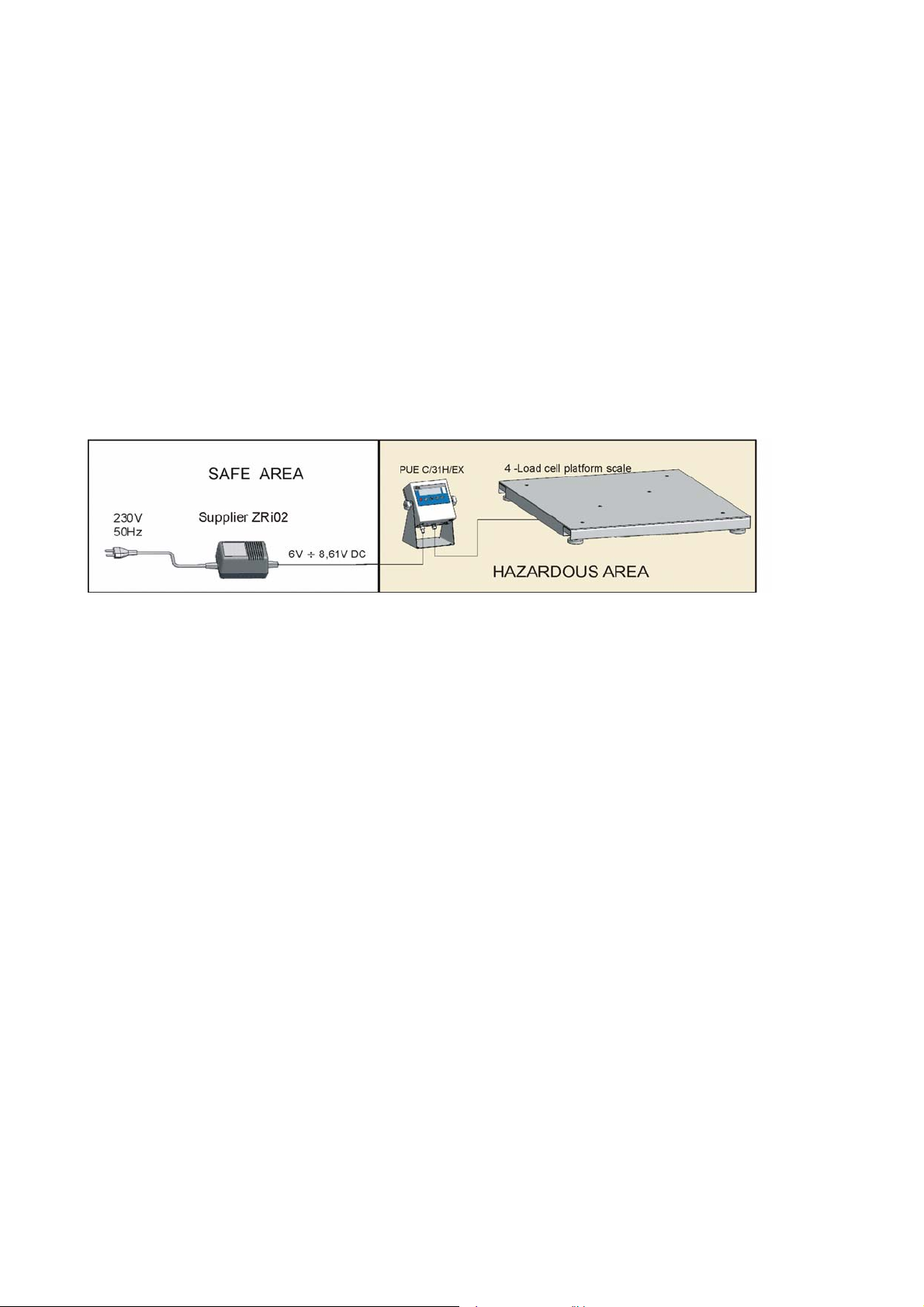
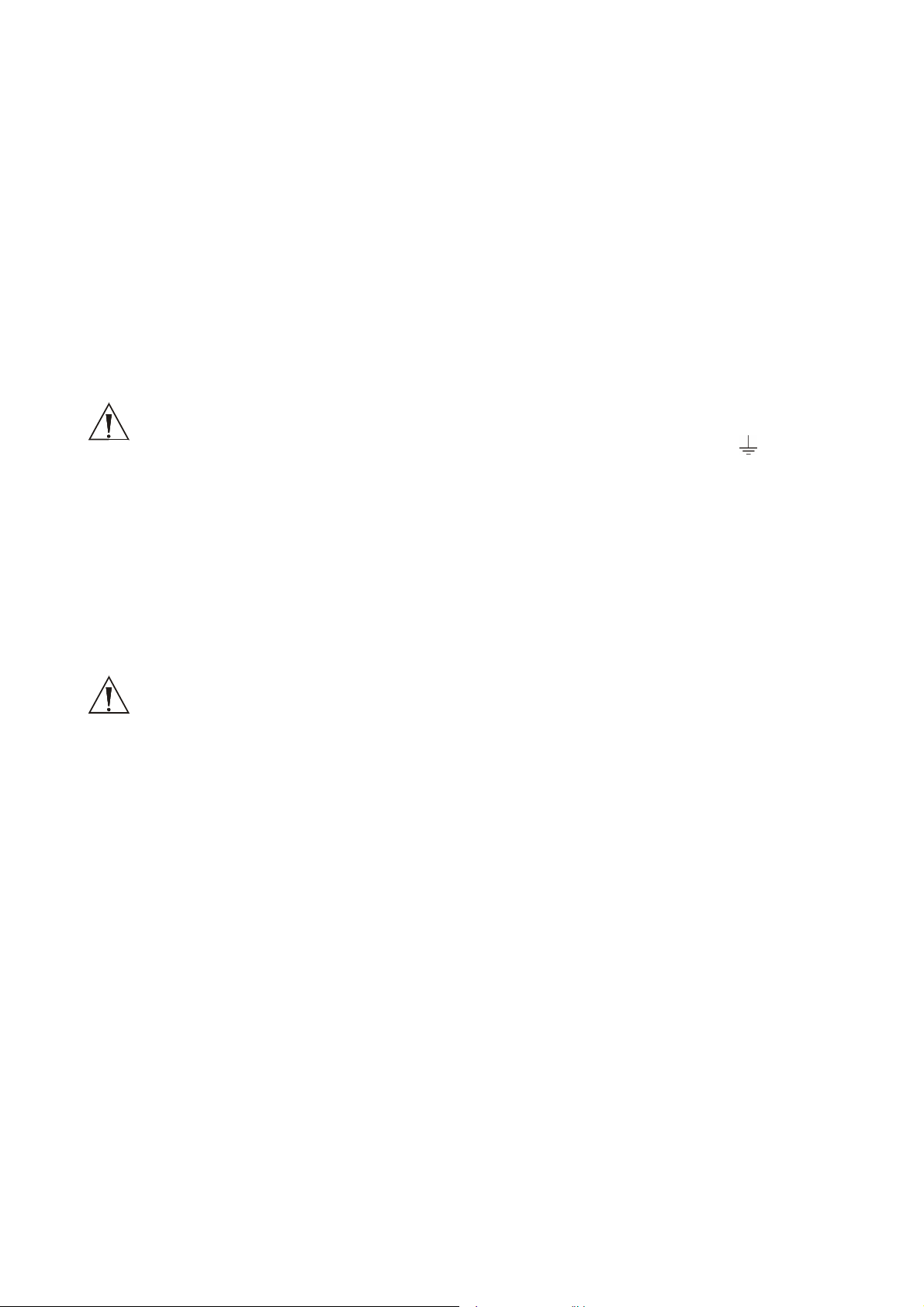
3. 4-LOAD CELL PLATFORMS IN WTC/4…C../EX.
Four load cell WTC/4…C../EX scales have modular construction and consist of:
• PUE C/31H/EX indicator
• ZRi02 power supplier made by RADWAG, for placing behind the hazardous area
• Load cells (Ex construction)
• Mechanical construction – non-electrical part
PUE C/31H/EX indicator is connected via a ~3m cable with a tensometer built-in in a steel
platform. This platform is equipped in a weight pan made of stainless steel.
The connecting cable is protected by a pliant pipe made of zirconium steel.
Indicators are supplied from ZRi02 power suppliers made by RADWAG placed outsider a
hazardous area.
The housing is connected to the weighing platform via a pliant pipe that is a conductor.
WTC/4…..C../EX scales with PUE C/31H/EX
- 6 -
4. WARNINGS AND SECURITY INFORMATION
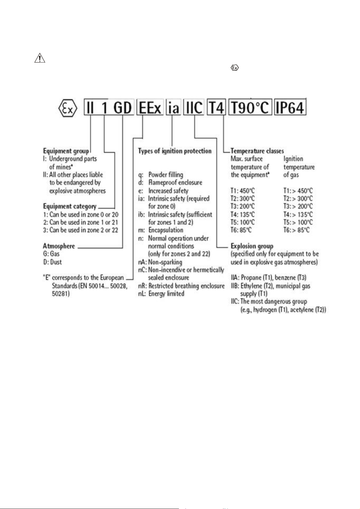
WTC/4…C../EX scales observe the requirements of the group II, category 2 of
devices compliant with 94/9/WE Directive and are marked - II 2 G IIB T4.
Symbology description according to 94/9/WE Directive:
- WTC/4…C../EX scales are intended to interior and outdoor operation. But it should not
be exposed to active chemical vapours, extreme temperatures and huge humidity.
Platform’s construction is made of mild steel, stainless steel tensometers are made with
IP68 (ingress protection rating).
- 7 -
Ambient temperature during operation: -10°C to +40°C.
- Scales cannot be exposed to mechanical shocks or vibrations.
WTC/4…C../EX scales can be installed and used only by a skilled, trained
personnel.
Scales should undergo periodical technical surveys .
Gathering electrostatic charge should be avoided. Earthing wire (equipotential)
needs to be always connected to the earthing terminal in PUE C/31H/EX indicator.
Disconnecting of the earthing wire is forbidden.
Equipotentialisation wire can be allowed only when the appearance of explosive
gases is impossible.
In case of any damage unplug the supply source, disconnect the supply cord and t
hen move the device to the safe area for temporarily storage to prevent it from using
until it is repaired.
PUE C/31H/EX indicators has an intrinsic safety construction that comprise with the
standards: PN-EN 50014 and PN-EN 50020 which is confirmed by KDB
06ATEX250 certificate.
The indicator is supplied from ZRi02 power supplier made by RADWAG, placed
outsider the hazardous area and compliant with: PN-EN 50014 and PN-EN 50020
standards - KDB 06ATEX251 certificate
Platforms are equipped in ATEX certified load cells SB14 Ex made by Flintec -
KEMA 02 ATEX 1123X certificate
Non-electrical elements of the platform are made according to PN-EN 13463-1
standard.
All repairs and maintenance work that require opening the indicator housing should
be made by authorised service of RADWAG. Subassemblies should be substituted
by original equivalents. If the scale is opened by unauthorised people all claims
connected with warranty are forfeiture.
- Any installation and maintenance work, that are at variance with this manual will
cause forfeiture of all warranty claims.
- 8 -
5. INSTALLATION INSTRUCTION OF WTC/4…C../EX
● For WTC/4…C../EX platform scales prepare an appropriate place for installation.
It should be dry, even and rigid. Acceptable operation temperature range -10°C to
+40°C.
The ground on which the platform is to be placed must be able to carry the maximal
load together with the platform.
○ WTC/4…C../EX scales are equipped in the indicator connected via ~3m cable.
The indicator can be mounted on the table or installed on a wall by means of a
handler.
● Scale should be unpacked outsider the hazardous area..
NOTICE !!
Equipotentialisation is required for the indicator.
The earthing wire should be connected to the terminal marked by „ ” .
● Before moving the scale to the place of operation prepare an earthing wire. This
wire should be terminated with an eye and should be screwed to the indicator using M4
nut. Use tooth lock washer to assure a constant force of holding down.
The equipotentialisation wire should be of yellow-green colour and minimal crosssection of 4mm².
● Install the device to the please of operation in the hazardous areas.
NOTICE!
Installing the platform and the indicator should be performer when the
appearance of the explosive atmosphere is impossible.
- 9 -
The way of earthing is shown below
● Weighings platform should be placed on an even, stable ground far from sources of
hit and draughts.
- Use an external large size level indication device to level the platform.
- Use levelling feet to regulate the level.
- If levelling is necessary proceeded as directed below:
○ Set the level by turning feet.
○ Then screw down the lock nuts to block the feet
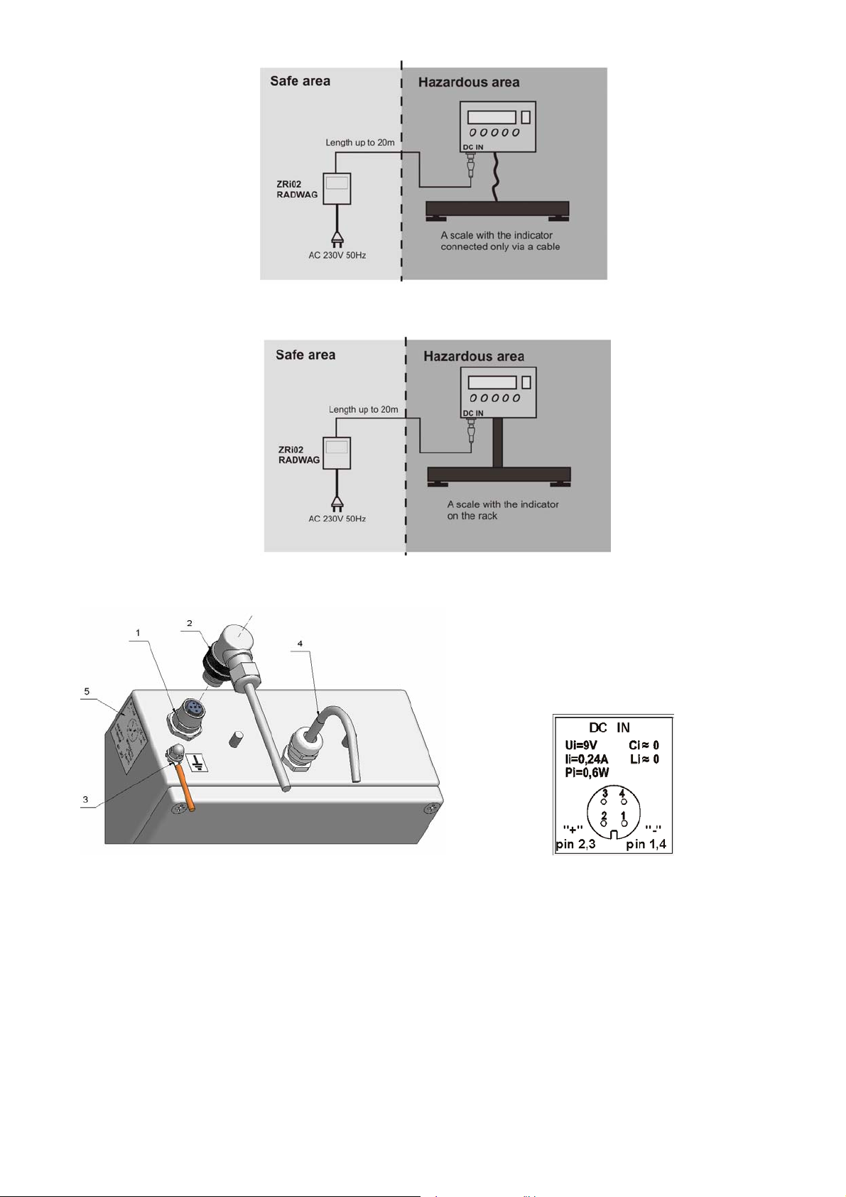
● Place the power supplier outside the hazardous area
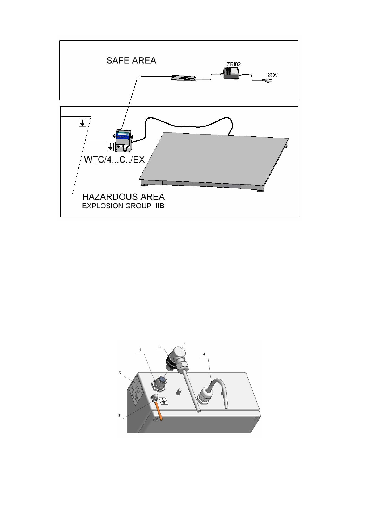
● Connect the (~20m) power supply cable to the DC IN socket in the PUE C/31H/EX
indicator,
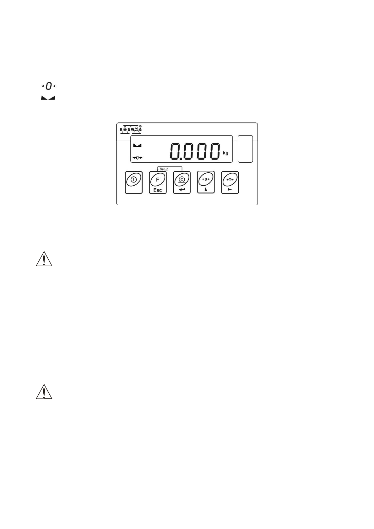
1 – Power supply socket
2 – Power supply socket
3 – Earthing terminal
4 – Tensometer cable
5 – Power supply socket description
- 10 -
Before the first start make sure that there is no danger of explosion (no explosive
gases). If there is any sign of inappropriate operation the scale should be unplugged
from the power source and then move the device to the safe area for temporarily
storage to prevent it from using until it is repaired.
● Connect the supplier to mains 230V AC
○ Un case of prolonged not using of the scale – unplug it from mains.
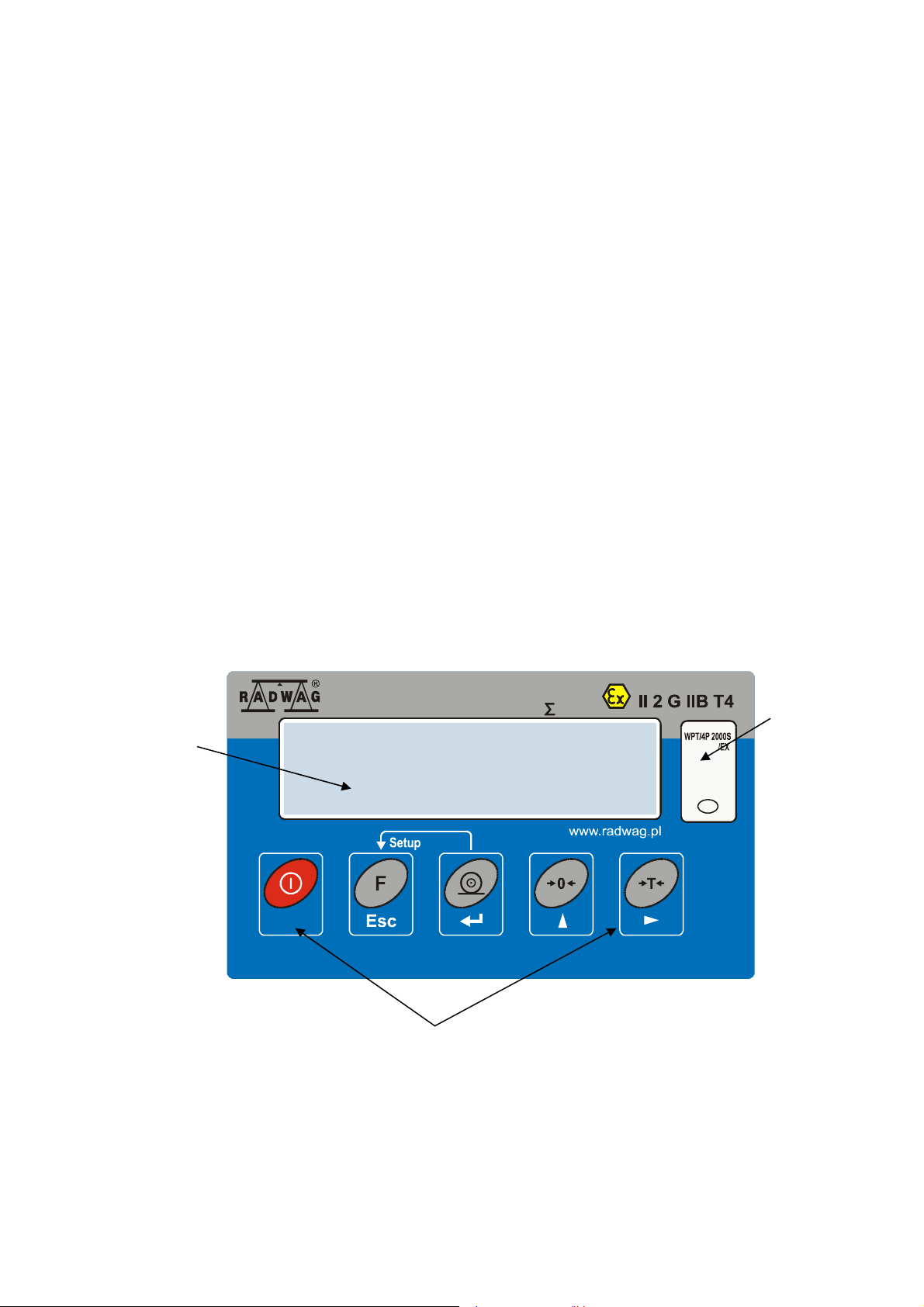
● Press ON/OFF to switch on the device – keep pressing it for about 1 sec.
Wait for the test completion, Then you will see zero indication and pictograms:
- zero indication
- stable result
kg - weight unit
- 11 -

6. CLEANING AND MAINTENANCE.
● Disconnect the ZRi02 power supplier from mains.
● Check the earthing connection quality.
Clean the scale and the housing with a slightly moistened cloth. You can use typical
domestic cleaning agents.
For clearing an overlay of the indicator do not use agents that can mechanically
scratch the surface. It includes an internal conductive layer that is important for save
operation.
Platform levelling feet and shock absorbers are made of rubber. Within the
hazardous area they need to be cleaned with a slightly moistened cloth. Moisture
protects against gathering electrostatic charges.
Cleaning should be performed when there are no explosive gases in the
atmosphere.
There is forbidden to us concentrated acids, bases, solvents or alcohol for
cleaning WPT/4P…H/EX scales.
There is also forbidden to use compressed air and high pressure washing
equipment.
7. TECHNICAL SURVEYS.
Technical surveys performed by the trained personnel at least once during every
three months.
● During every survey following things should be checked:
− earthing quality: the quality of fastening to the housing and the resistance of
connection - max. 100Ω,
− quality of the connection between the platform and the indicator (pliant steel pipe
connecting the two subassemblies).
The damage and loosing one of connection is inadmissible.
− electrical connection between the housing and the platform - max. resistance
between the weight pan (put on) and the housing should be lower than 100Ω.
− stability and levelling of the scale.
- 12 -
8. GETTING STARTED
8.1. Unpacking and placing
• The scale should be unpacked outside the hazardous area.
• Before moving the scale to the place of operation prepare a cable for earthing the
device against electrostatic charges.
Notice!!
In order to protect against gathering electrostatic charge it is necessary to
earth/zero the housing of the indicator.
Connect the earthing lead/wire to the place marked with „ ” .
See the manual for details about earthing.
• Situate the scale in a destination place and connect earthing/zeroing.
NOTICE!
Mounting the indicator, placing the weighing platform and earthing/zeroing
should be performed when the explosive atmosphere cannot appear.
Indicators with cable can be mounted on the rack, on the wall or on the table using
a special holder.
Weighings platform should be placed on even and stable ground far from sources of hit
and draughts. It should be also levelled out using the feet..
8.2. Connecting of supplier
1. Place the power supplier behind the hazardous area
2. Connect the plug that terminates the supply cable (up to 20m) to the socket marked
as DC IN
3. connect the supplier to mains (230V AC)
4. In case of not using the scale unplug it from the mains
NOTICE:
• Scales with PUE C/31H/EX indicators can be supplied only from ZRi02 power
suppliers II (2) G [EEx ib] IIC 06ATEX251 of RADWAG production, placed
outside the hazardous area or another with identical parameters of the supply
circuit (intrinsic safety).
- 13 -
Connation of supplier
1 – Power supply socket
2 – Power supply socket
3 – Earthing terminal
4 – Tensometer cable
5 – Power supply socket description
- 14 -
Power supply socket description
8.3. Switching on
• Press the ON/OFF key– keep pressing for about 1 sec
• After switching on wait for the test completion
• You will see the indication equal zero and following pictograms:
- zero indication
- equilibrium
kg or g - weighing mode
Ready to use.
9. CLEANING
Cleaning can be performed only after unplugging from mains
(230V AC). Use agents and materials that do not cause gathering
electrostatic charges on elements of the supplier. Do not use abrasive
agents and solvents because it can causa the damage of the casing.
..........Cleaning should be performed when the appearance of explosive gases is impossible.
10. SERVICE AND REPAIRING
In case of any problems with appropriate operation of the indicator contact with the
manufacturer’s service or any authorised service of RADWAG.
In case of any fault or dysfunction the device should be passed to the manufacturer’s
service or any authorised service of RADWAG or inform about it in order to settle the
conditions of repair.
Any intrusion (alteration, repair etc.) in the indicator or scale based on PUE
C/31H/EX indicator by unauthorised persons will cause a forfeiture of
validity of certificates, declarations and manufacturer’s warranty.
- 15 -
11. FUNCTIONS
• Filtering
• Autozero
• Minimal mass
• Counting pieces
• +/- control
• Deviation in per cents
• Top indication latch
• Automatic tare
• Tare memory
• Manual tare inscription
• User’s calibration
• Totalizing
Operation functions can be enabled/disabled for users in parameters. See the further part
of the manual.
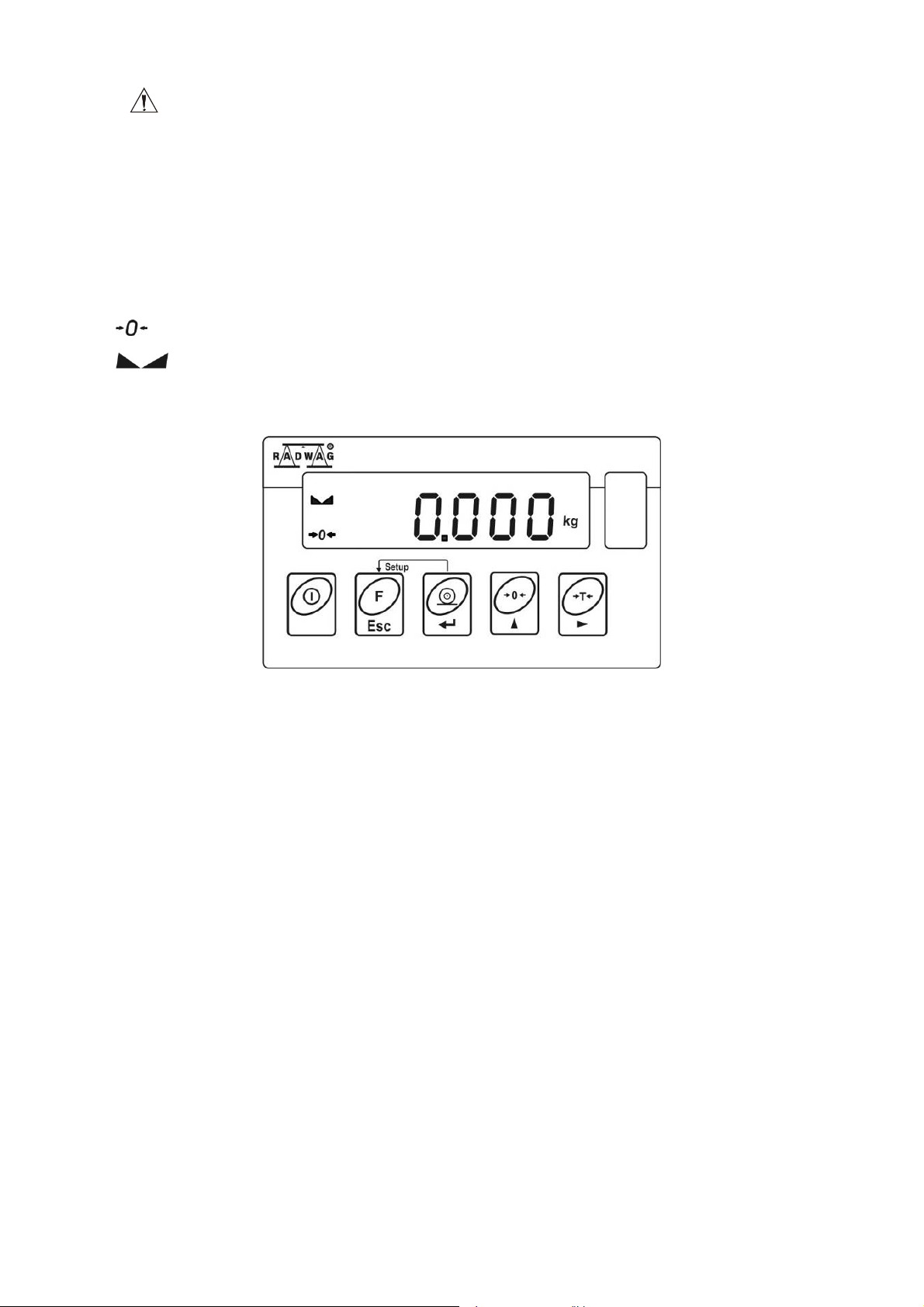
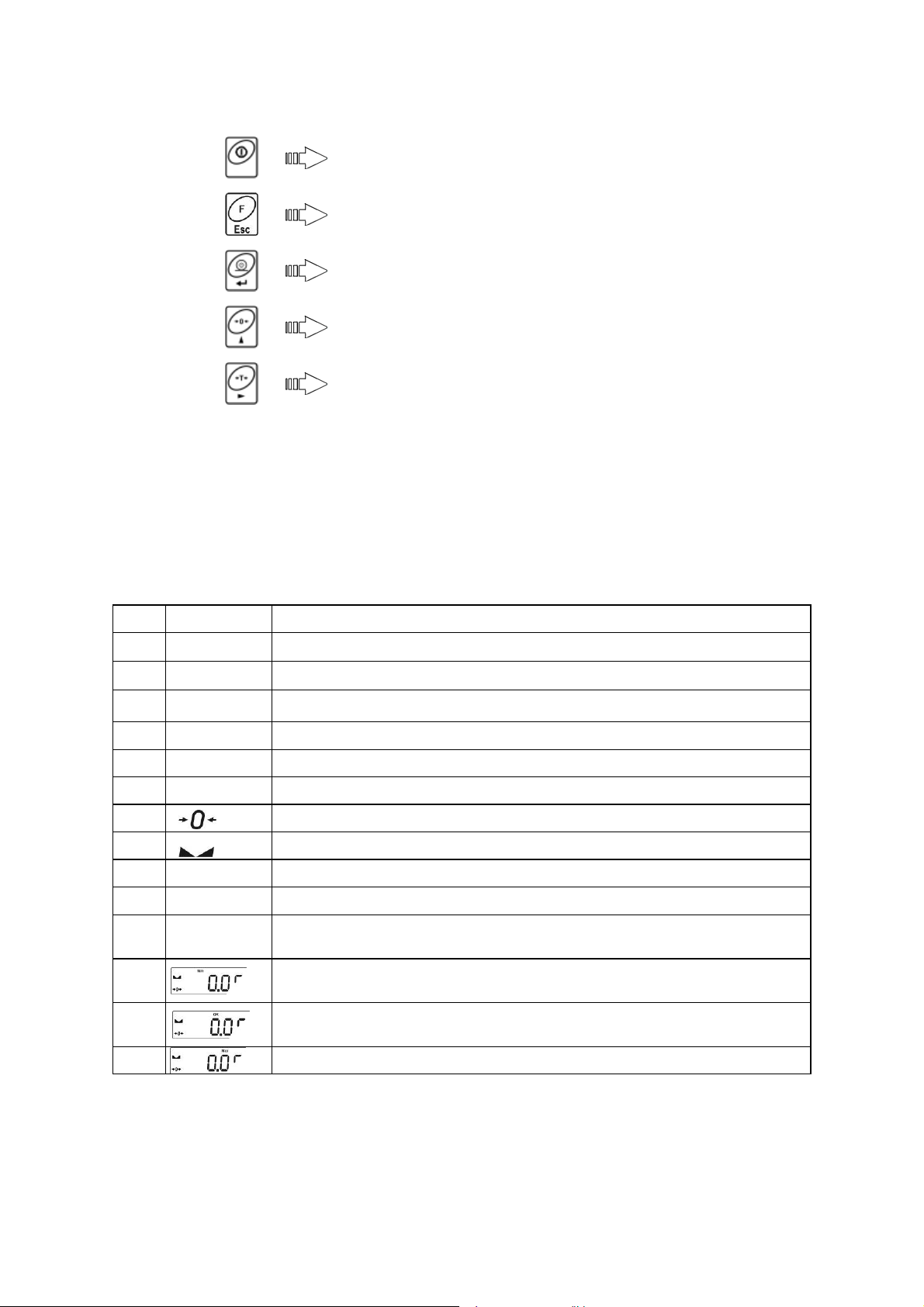
12. KEYBOARD
Display
window
Function keys – „keypad”
Max 2000kg
Min 20kg
d=0,1kg
e=1kg
T=-2000kg
II
Information
window
- 16 -
13. FUNCTIONS OF KEYS
Power on/off – keep it pressed for about
1 sec
- function key (selection of operation mode)
Confirmation of changes
- zeroing
- tarring
Notice:
After pressing F +PRINT functions of keys change during setting parameters. See the
further part of the manual for details.
14. INSCRIPTIONS AND PICTOGRAMS
O.n. inscription Description
1. FIL
2. PCS
3.
HiLo
4. Auto
5. toP
6. Add
7.
8.
9.
10.
11.
PCS
kg (g)
Net
12.
13.
14.
Filtering level
Counting pieces
Control and correction of zero indication of scale
Measurement of max. force influencing weighing pan
Totalizing
Scale in autozero range (indication = precise zero)
Result of measurement is stable (ready for readout)
Scale in operating mode counting pieces
Scale in operating mode weighing
Scale is tarred.
+/- control in relation to reference mass – setting lower
threshold or mass below first range
+/- control in relation to reference mass: mass of load
between set threshold
+/- control in relation to reference mass – setting upper
threshold or mass above upper threshold.
Control and correction of zero indication of scale
- 17 -

15. USER MENU
The menu is divided into 5 basic groups. Each group has its individual name starting with
the capital letter P.
Names of groups and their contents are shown below.
P1 rEAd
P1.1 FiL | 2
P1.2 Auto | YES
P1.3 tArA | no
P1.4 Fmd | no
P2 Prnt
P2.2 S_Lo |
P3 Unit
P3.1 StUn | kg
P4 Func
P4.1 FFun | ALL
P4.2 Funi | No
P4.3 PcS | No
P4.4 HiLo | No
P4.5 PrcA | No
P4.6 Prcb | No
P4.7 AtAr | No
P4.8 toP | No
P4.9 Add | No
P6 CAL
P6.1 St_u |
P6.2 uCAL |
- 18 -
 Loading...