

RADWAG WTC 600.1, WTC 200, WTC 2000, WTC 3000 User Manual

WTC
WTC 200 Precision Balance
WTC 600.1 Precision Balance
WTC 2000 Precision Balance
WTC 3000 Precision Balance
USER MANUAL
ITKU-95-03-11-16-EN
www.radwag.com

- 2 -
NOVEMBER 2016

- 3 -
CONTENTS
1. GENERAL INFORMATION .......................................................................................................................... 5
2. PRECAUTIONS ............................................................................................................................................ 5
2.1. Maintenance ......................................................................................................................................... 5
2.2. Battery .................................................................................................................................................. 5
3. WARRANTY CONDITIONS .......................................................................................................................... 6
4. BALANCE DESIGN ...................................................................................................................................... 6
4.1. Dimensions ........................................................................................................................................... 6
4.2. Connection Cables - Diagrams ............................................................................................................ 8
4.3. Connectors Description ........................................................................................................................ 8
5. UNPACKING AND INSTALLATION ............................................................................................................ 8
6. START-UP .................................................................................................................................................... 9
6.1. Levelling ............................................................................................................................................... 9
6.2. Powering the Device ............................................................................................................................ 9
6.3. Battery Status ....................................................................................................................................... 9
6.4. Battery Power ..................................................................................................................................... 10
7. MAINTENANCE ACTIVITIES ..................................................................................................................... 10
7.1. Cleaning ABS Components ............................................................................................................... 10
7.2. Cleaning Stainless Steel Components ............................................................................................... 10
8. TEMPERATURE STABILIZATION ............................................................................................................ 11
9. KEYPAD ..................................................................................................................................................... 11
10. KEYS ........................................................................................................................................................ 11
11. PROGRAM ............................................................................................................................................... 12
12. OPERATING BALANCE MENU .............................................................................................................. 16
12.1. Keypad .............................................................................................................................................. 16
12.2. Return to the Weighing Mode ........................................................................................................... 17
13. WEIGHING ............................................................................................................................................... 17
13.1. Taring ................................................................................................................................................ 18
13.2. Manual Tare Entering ....................................................................................................................... 18
13.3. Zeroing .............................................................................................................................................. 19
13.4. Weighing for Dual Range Balances .................................................................................................. 19
13.5. Units ................................................................................................................................................ 20
13.5.1. Start Unit .............................................................................................................................. 20
13.5.2. Temporary Unit ..................................................................................................................... 20
14. BALANCE PARAMETERS ...................................................................................................................... 21
14.1. Filter Level ........................................................................................................................................ 21
14.2. Value Release ................................................................................................................................... 21
14.3. Balance Ambient Conditions ............................................................................................................. 22
14.4. Autozero ............................................................................................................................................ 22
14.5. Tare ................................................................................................................................................ 23
14.6. Last Digit ........................................................................................................................................... 23
15. ADJUSTMENT ......................................................................................................................................... 23
15.1. External Adjustment .......................................................................................................................... 24
15.2. User Adjustment ............................................................................................................................... 24
15.3. Adjustment Report ............................................................................................................................ 25
16. INTERFACES ........................................................................................................................................... 25
16.1. RS232 Settings ................................................................................................................................. 25
16.1.1. Baud Rate ............................................................................................................................ 26
16.1.2. Parity .................................................................................................................................... 26
17. PERIPHERALS ........................................................................................................................................ 26
17.1. Computer .......................................................................................................................................... 26
17.1.1. Computer Port ...................................................................................................................... 26
17.1.2. Continuous Transmission ..................................................................................................... 27
17.1.3. Interval For Printouts During Continuous Transmission ....................................................... 27
17.2. Printer ............................................................................................................................................... 27
17.2.1. Printer Port ........................................................................................................................... 27
18. PRINTOUTS ............................................................................................................................................. 28
18.1. Adjustment Report Printout ............................................................................................................... 28
18.2. GLP Printout ..................................................................................................................................... 29

- 4 -
19. MISCELLANEOUS ................................................................................................................................... 29
19.1. Backlight ........................................................................................................................................... 30
19.2. 'Beep' Sound ..................................................................................................................................... 30
19.3. Automatic Shutdown ......................................................................................................................... 30
19.4. Date ................................................................................................................................................ 31
19.5. Time ................................................................................................................................................ 31
19.6. Date Format ...................................................................................................................................... 32
19.7. Time Format...................................................................................................................................... 32
19.8. User Menu Default Settings .............................................................................................................. 32
20. INFORMATION ......................................................................................................................................... 33
21. WORKING MODES .................................................................................................................................. 33
21.1. Running Working Mode .................................................................................................................... 33
21.2. Working Modes Settings ................................................................................................................... 33
21.3. Weighing ........................................................................................................................................... 34
21.3.1. Working Mode Accessibility ................................................................................................. 34
21.3.2. Save Mode ........................................................................................................................... 34
21.3.3. LO Threshold ........................................................................................................................ 35
21.4. Parts Counting .................................................................................................................................. 35
21.4.1. Working Mode Accessibility ................................................................................................. 35
21.4.2. Selecting Working Mode ...................................................................................................... 35
21.4.3. Save Mode ........................................................................................................................... 36
21.4.4. LO Threshold ........................................................................................................................ 36
21.4.5. Setting Reference Mass by Entering Mass of a Single Part ................................................. 36
21.4.6. Setting Reference Mass by Determining Mass of a Single Part ........................................... 36
21.5. +/- Control ......................................................................................................................................... 37
21.5.1. Working Mode Accessibility ................................................................................................. 38
21.5.2. Save Mode ........................................................................................................................... 38
21.5.3. LO Threshold ........................................................................................................................ 38
21.5.4. Declaring Checkweighing Thresholds .................................................................................. 38
21.6. Percent Weighing Against Reference Sample Mass ........................................................................ 39
21.6.1. Working Mode Accessibility ................................................................................................. 39
21.6.2. Selecting Working Mode ...................................................................................................... 39
21.6.3. Save Mode ........................................................................................................................... 40
21.6.4. LO Threshold ........................................................................................................................ 40
21.6.5. Reference Mass Determined by Weighing ........................................................................... 40
21.6.6. Reference Mass Determined by Entering............................................................................. 40
21.7. Peak Hold ......................................................................................................................................... 41
21.7.1. Working Mode Accessibility ................................................................................................. 41
21.7.2. LO Threshold ........................................................................................................................ 41
21.7.3. Means of Operation .............................................................................................................. 41
21.8. Totalizing ........................................................................................................................................... 42
21.8.1. Working Mode Accessibility ................................................................................................. 42
21.8.2. Save Mode ........................................................................................................................... 42
21.8.3. LO Threshold ........................................................................................................................ 42
21.8.4. Totalizing Procedure ............................................................................................................ 42
22. DIAGRAMS OF CONNECTION CABLES ............................................................................................... 44
23. COMMUNICATION PROTOCOL ............................................................................................................. 44
23.1. General Information .......................................................................................................................... 44
23.2. List of Commands ............................................................................................................................. 45
23.3. Response Format ............................................................................................................................. 45
23.4. Commands Overview........................................................................................................................ 46
23.5. Manual Printout / Automatic Printout ................................................................................................ 52
23.6. Continuous Transmission ................................................................................................................. 53
24. TECHNICAL SPECIFICATIONS .............................................................................................................. 54
25. TROUBLESHOOTING ............................................................................................................................. 54
26. ERROR MESSAGES ............................................................................................................................... 55
27. ADDITIONAL EQUIPMENT ..................................................................................................................... 55

- 5 -
1. GENERAL INFORMATION
W TC precision balance enables fast and accurate m ass measur ements under
laboratory conditions.
The weighing pan, made of stainless steel and equipped with anti-draft shield,
is an integral part of WTC balance. Backlit LCD display ensures clear
measurem ent result. W T C balance is equipped with an internal battery (comes
standard), so it does not have to be connected to the mains.
WTC balance is equipped with the following interfaces: RS 232, USB type A,
USB type B. The interfaces enable cooperation between the balance and
peripheral devices (e.g. printer, computer, flash drive).
2. PRECAUTIONS
2.1. Maintenance
A. Prior first use, carefully read this User Manual. Use the balance only as
intended.
B. Balance to be decommissioned, should be decommissioned in accordance
with valid legal regulations.
2.2. Battery
WTC balance is supplied by NiMH-type battery (nickel-metal-hydrogen) of
1800-2800mAh capacity.
In case of prolonged storage of the balance in low temperature,
the battery has to be charged.
A worn out battery can be replaced only by the manufacturer or
by the authorized service.
The equipment including accumulators does not belong to
regular household waste. The European legislation requires
electric and electronic equipment to be collected and disposed
separately from other communal waste with the aim of being
recycled.
- 6 -
Notice:
Symbols on accumulators identify harmful compounds: Pb = lead, Cd =
cadmium, Hg = mercury.
3. WARRANTY CONDITIONS
A. RADW AG f eels obliged to repair or ex change all elem ents that appear to
be faulty by production or by construction,
B. Defining defects of unclear origin defects and m eans of their elimination
can only be realized with assistance of manufacturer and user
representatives,
C. RADW AG does not bear any responsibility for defects or losses resulting
from unauthorized or inadequate performing of production or service
processes,
D. Warranty does not cover:
• mechanical defects caused by product exploitation other than
intended, defects of thermal and chemical origin, defects caused by
lightning, overvoltage in the power network or other random event,
• Inappropriate cleaning.
E. Loss of warranty takes place if:
• a repair is carried out outside RADWAG authorized service point,
• service claim s intrusion into mechanical or electronic construction by
unauthorized people,
• the balance does not bear company protective stickers.
F. Warranty conditions outline the warranty period for rechargeable
batteries attached to the balance for 12 months.
G. For detailed warranty conditions go to the warranty certificate.
H. Contact with the central authorized service: (0-48) 384 88 00 ext. 106
and 107.
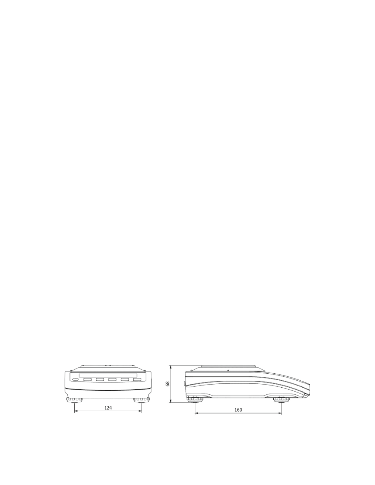
4. BALANCE DESIGN
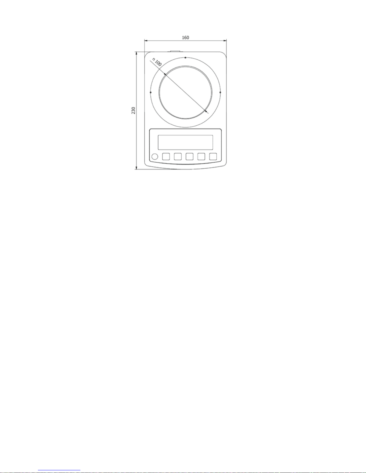
4.1. Dimensions
- 7 -
Fig.1. Dimensions of WTC 200 precision balance.
Fig.2. Dimensions of WTC 600.1, WTC 2000 and WTC 3000 precision balances.
- 8 -
4.2. Connection Cables - Diagrams
Fig. 3. Interfaces view
DC IN - power outlet
RS232 - RS 232 connector
USB 2 - USB 'device' connector
USB 1 - USB 'host' connector
4.3. Connectors Description
Pin2 – RxD
Pin3 – TxD
Pin5 – GND
RS 232 DB9/M
connector (male)
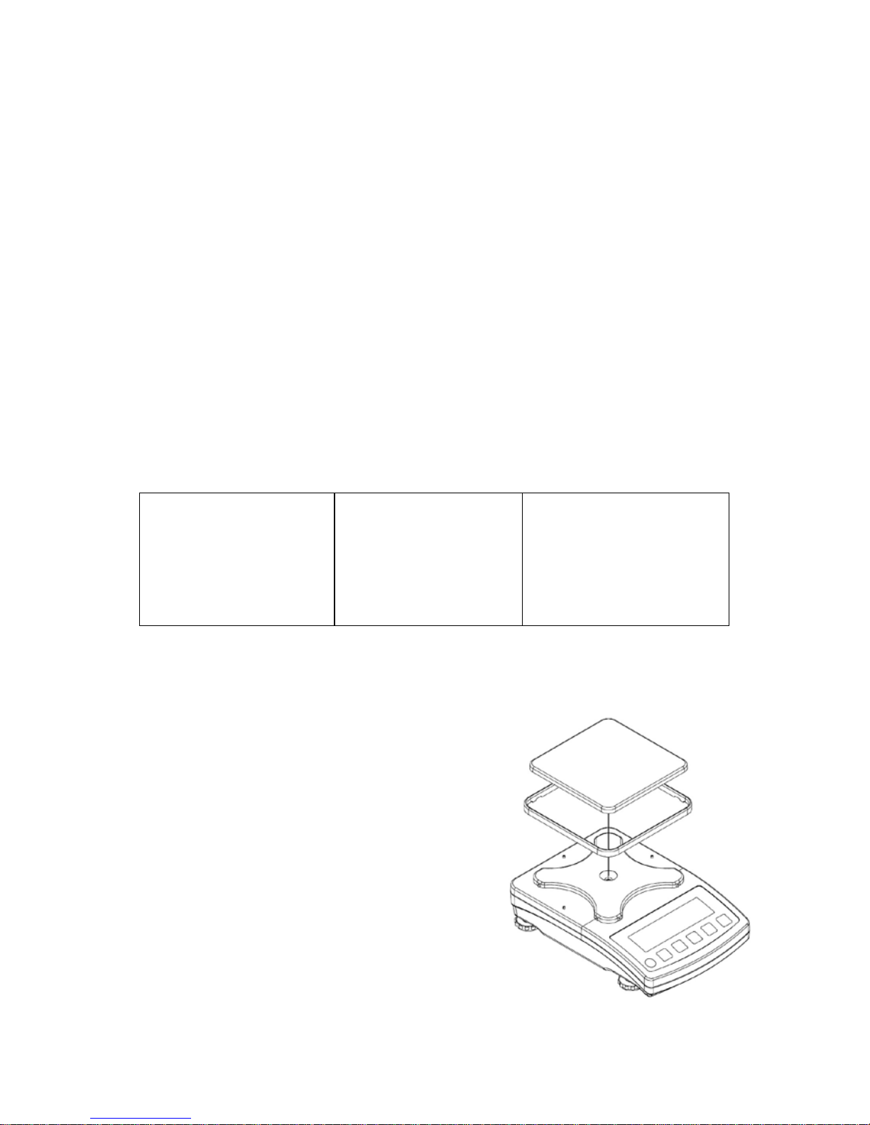
5. UNPACKING AND INSTALLATION
A. Take the device out of the packaging.
B. Place the balance on a flat and even
surface. Keep it far away from any
sources of heat.
C. Install the weighing pan and anti-draft
shields in accordance with fig.4.
Fig. 4. Balance installation
- 9 -
6. START-UP
6.1. Levelling
• Prior first use level the balance. To level a balance
turn its feet, keep turning the feet until the air
bubble takes central position.
6.2. Powering the Device
Caution:
Balance can be c onnected to the mains only with a power adapter that comes
standard with the particular model. Nominal power supply of the power adapter
(specified on the power adapter data plate) has to be compatible to the power
from the mains.
Plug the balance to the mains – connec t the power adapter to the socket, next
connect its connector to interface located at the back of the balance housing.
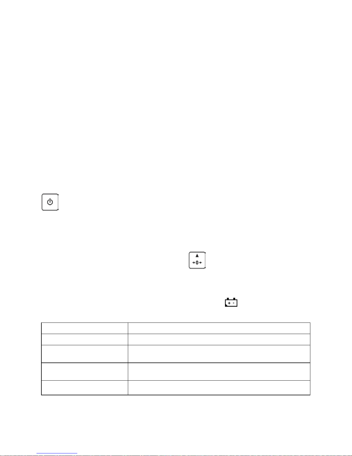
Turn the balance on or off using key.
Test of the display unit takes place right after connecting the balance to the
power, all the elements and pictograms are backlit for a short time. Next, the
name and the program number appear, the indication gets to ZERO (displayed
reading unit depends on the balance).
If the indication is different than zero, press
button.
6.3. Battery Status
An internal battery comes standard with the balance. pictogram , displayed
at the top of the display, signals battery status.
Pictogram operation Overview
No pictogram Battery full. S t andard bal ance operation.
Pictogram di s pl ayed
continuously
Battery status low. The balance will shut down. Immediately
charge the battery.
Pictogram bl i nk s every 1 s.
Battery charging. Balance connected to power supplier, the
battery is being charged.
Pictogram bl i nk s every 0.5
s.
Battery error. Battery damaged.

- 10 -
6.4. Battery Power
• Simultaneously press and keys.
• Battery power given in % is displayed for 2s.
• Wait for the home screen to be displayed.
7. MAINTENANCE ACTIVITIES
Disassembly a weighing pan and other detachable components (the
components differ depending on a balance type – see: UNPACKING AND
INSTALLATION section).
Caution:
Cleaning anti-draft chamber while still installed may cause damage of the
measuring system.
7.1. Cleaning ABS Components
To clean dry surfaces and avoid smutching use clean non-colouring cloths
made of cellulose or cotton. You can use a solution of water and detergent
(soap, dishwashing detergent, glass cleaner). Gently rub the cleaned surface
and let it dry. Repeat cleaning process if needed.
In the case when contam ination is hard to r em ove, e.g. adhesive, rubber, r esin,
polyurethane foam residues etc., you can use a special cleaning agents based
on a mixture of aliphatic hydrocarbons that do not dissolve plastics. Before
using the cleanser for all surfaces we recommend carrying out tests. Do not
use products containing abrasive substances.
7.2. Cleaning Stainless Steel Components
Avoid using cleansers containing any corrosive chemicals, e.g. bleach
(containing chlorine). Do not use products containing abrasive substances.
Always remove the dirt using microfiber cloth to avoid damage of protective
coating.
In case of a daily maintenance:
1. Remove the dirt using cloth dipped in warm water.
2. For best results, add a little dishwashing detergent.

- 11 -
8. TEMPERATURE STABILIZATION
• For correc t operation of the balanc e the tem perature has to range +15˚C ±
+30˚C;
• On switching on, the balance requires 30 minutes of temperature
stabilization time.
• During temperature stabilization displayed information may change.
• Adjustment has to be carried out after temperature stabilization.
• Any changes of temperature and humidity during operation can cause
indications errors. Errors can be corrected by carrying out user adjustment.
9. KEYPAD
Fig. 5. WTC series keypad
10. KEYS
Press to switch the balance on/off
Function button: press to select respective operation mode.
Press to send the weighing result to a printer or a computer.
Press to zero the balance.
Press to tare the balance.

- 12 -
Caution:
On pressing
and ) keys balance menu is displayed and keys'
functions change. F or detailed overview of k eys' functions go further down this
user manual.
11. PROGRAM
Main menu is divided into function groups. Function group is a group of
interrelated parameters.
Parameter No. Name Options Overview
P1. CAL Adjustment
1.1. CA-E - External adjus tment
1.2. CA-U - User adjustment with external weight
P2.
rEAd - Balance parameters
2.1. FIL 1, 2, 3 Filter
2.2. APPr FASt, PrEc, F_P Value release
2.3.
Enut
StAb, nStAb
Environment
2.4.
Aut
YES, no
Autozero
2.5. tare no, tArF, AtAr, EAcH Tare
2.6. ttr tArEH, tArnn Tare implementing method
2.7. LdiG ALAS, nEur, uuSt Last digit
P3.
Func
-
Working modes
3.1.
UUGG
-
Weighing
3.1.1
.
Acc YES, no Working mode On/Off
3.1.2
.
Snn StAb, nStAb, rEPL Save mode
3.1.3
.
Lo - LO Threshold
3.2. PCS - Parts counting
3.2.1
.
Acc YES, no Working mode On/Off
3.2.2
.
UUT S_s, Suu Working mode
3.2.3
.
Snn StAb, nStAb, rEPL Save mode
3.2.4
.
Lo - LO Threshold
3.3. HiLo - +/- control
3.3.1
.
Acc YES, no Working mode On/Off

- 13 -
3.3.2
.
Snn StAb, nStAb, rEPL Save mode
3.3.3
.
Lo - LO Threshold
3.4. dEu - P ercen t weighing

- 14 -
3.4.1
.
Acc YES, no Working mode On/Off
3.4.2
.
UUT S_s, Suu W ork i ng mode
3.4.3
.
Snn StAb, nStAb, rEPL Save mode
3.4.4
.
Lo - LO Threshold
3.5. toP - P eak h o l d
3.5.1
.
Acc YES, no Working mode On/Off
3.5.2
.
Lo - LO Threshold
3.6.
Add
-
Totalizing
3.6.1
.
Acc YES, no Working mode On/Off
3.6.2
.
Snn StAb, nStAb, rEPL Save mode
3.6.3
.
Lo - LO Threshold
P4.
Conn
-
Interfaces
4.1.
rS - RS232 parameters settings
4.1.1
.
bAd
2400, 4800, 9600,
19200, 38400, 57600,
115200
RS 232 baud rate
4.1.2
.
PAr nonE, Odd, EuEn Parity
P5.
ducE - Peripherals
5.1.
PC - Computer
5.1.1
.
Prt nonE, rS232, USbB Computer port
5.1.2
.
Cnt nonE , CntA, Cntb Continuous Transmis s i on
5.1.3
.
Int 0.1[s] - 1000[s] Continuous transm i ssion time i nterval
5.2.
Prtr
-
Printer
5.2.1
.
Prt nonE, rS232, USbb Printer port
P6.
Prnt
Printouts
6.1. CrEP - Adjustment report
6.1.1
.
CtP YES, no Adjustment type
6.1.2
.
dAt YES, no Date
6.1.3
.
tin YES, no Time
6.1.4
.
Idb YES, no Balance S/N
6.1.5
.
CdF YES, no Adjustment difference

- 15 -
6.1.6
.
dSh YES, no Dashes
6.1.7
.
SiG YES, no Signature
6.2. GLP - GLP Printout
6.2.1
.
dAt YES, no Date
6.2.2
.
tin YES, no Time
6.2.3
.
n YES, no Net
6.2.4
.
t YES, no Tare
- 16 -
6.2.5
.
b YES, no Gross
6.2.6
.
CrS YES, no Current result
6.2.7
.
CrP YES, no Adj ustment report
P7.
Misc
Miscellaneous
7.1. bLbt
no, 10, 20, 30, 40, 50,
60, 70, 80, 90, 100
Backlit level in [%]
7.2. bEEP YES, no Key sound
7.3. t1 nonE, 1, 2, 3, 5, 10 Time-defined finish mode
7.4.
SdAt
-
Date
7.5.
Stnn
-
Time
7.6. FdAt 1, 2, 3, 4 Date format
7.7. Ftin 12H, 24H Time form at
7.8. dFLu - User default set tings
P8.
InFo
Information on balance
8.1. Idb - Balance serial number
8.2. PurS - Program version
P9.
Unit - Units
9.1. UnSt g, kg, N, ct, lb Start unit
9.2. Unin g, kg, N, ct, lb
Temporary unit valid unti l t he bal ance
is turned off.
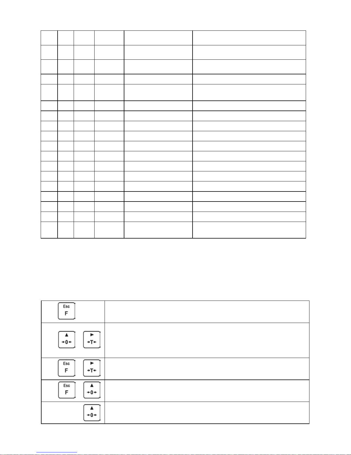
12. OPERATING BALANCE MENU
Use keypad to navigate in menu.
12.1. Keypad
+
Press to enter 'Main Menu'
+
Press to manually enter tare
Press to enter tare from tare values database
Press to edit parameter value and to change it by 1 digit up
Press to move the menu up
+
Press to check battery status
+
Press to preview date/time
Press to move the menu down
Press to change current parameter value
- 17 -
Press to enter particular submenu
Press to select parameter that is to be modified
Press to confirm introduced modifications
Press to leave, parameter remains unmodified
Press to move one menu level up
12.2. Return to the Weighing Mode
Any changes made in balance's memory are automatically saved on return to
the main window.
To return to the main window press key.
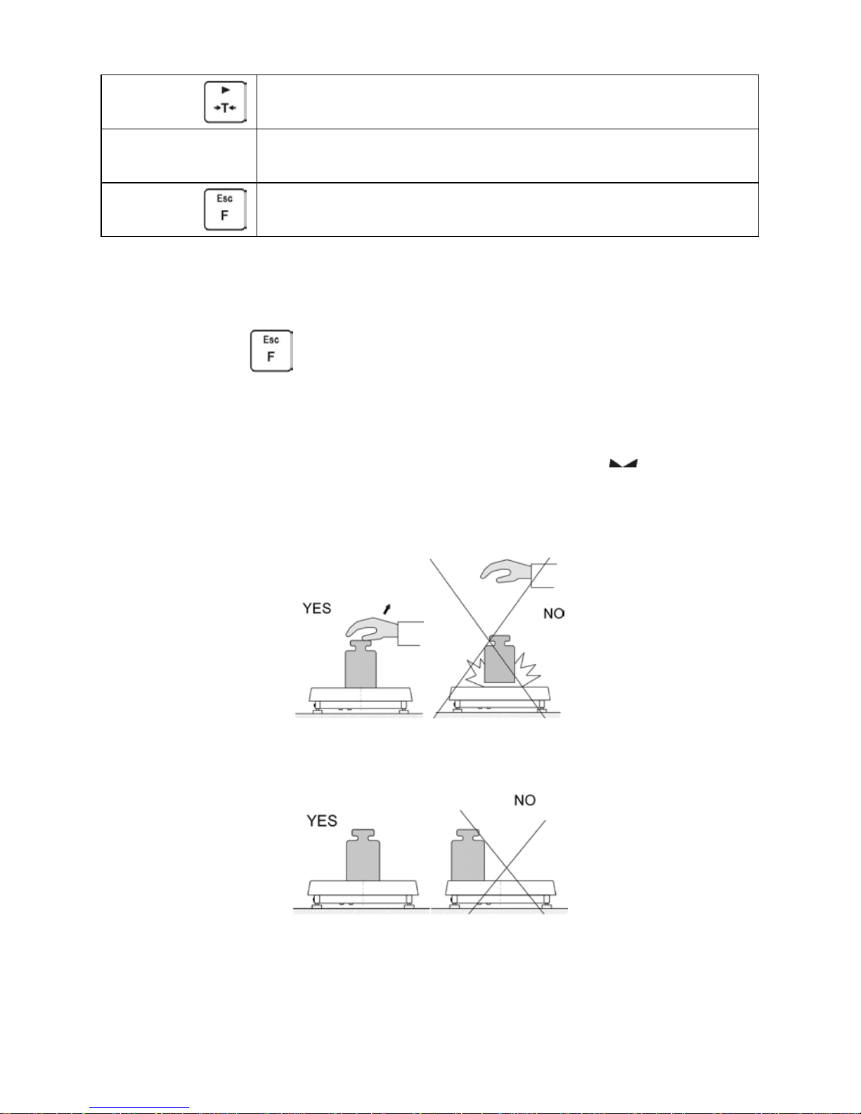
13. WEIGHING
Load the weighing pan. You can read weighing result when , pictogram is
displayed. To assure long-term operation and correct mass measurements
follow the rules presented below:
• Load the weighing pan steadily avoiding shocks:
• Place weighed loads centrally on the weighing pan (eccentricity errors are
specified by PN-EN 45501 standard, points 3.5 and 3.6.2.):
 Loading...