

RADWAG WPY/KO series, WPY 500/KO, WPY 1000/KO, WPY 2000/KO User Manual

User Manual
Scales of WPY/KO series
Manual number:
ITKU-47-06-03-10-A
Mass Comparator
MANUFACTURER OF ELECTRONIC
WEIGHING INSTRUMENTS
RADWAG Wagi Elektroniczne, 26–600 Radom Bracka 28 Street - POLAND
Phone +48 48 38 48 800, phone/fax. +48 48 385 00 10
Selling department +48 48 366 80 06
www.radwag.com

MARCH 2010
2

Table OF CONTENTS
1. INTENDED USE ..........................................................................................................................7
2. PRECAUTIONARY MEASURES ................................................................................................7
3. WARRANTY CONDITIONS........................................................................................................7
4. ACKING AND MOUNTING..................................................................................................8 UNP
5.
CONSTRUCTION........................................................................................................................9
5.1. Main dimensions ..................................................................................................................9
5.2. Description of connectors ...................................................................................................10
5.2.1. .............................................................................10 Connectors’ description in PUE 7
5.2.2.
...........................................................................10 Connectors’ description in PUE 7P
..................................................................................10 Description of glands PUE 7P
5.2.3.
5.2.4.
Connector with RS232 and I/O................................................................................. 11
6. GETTING STARTED .................................................................................................................11
7. KEYPAD OVERLAY..................................................................................................................12
8. .............................................................................................................12 FUNCTIONS OF KEYS
9.
PROGRAM STRUCTURE.........................................................................................................13
9.1. Main menu items ................................................................................................................13
9.1.1. ...............................................................................................................13 Parameters
.................................................................................................................14 Databases
9.1.2.
Scale Info..................................................................................................................14 9.1.3.
9.2.
Inventory of parameters .....................................................................................................15
9.2.1. s - weighing .................................................................................... 15 Scale parameter
9.2.2.
.........................................................................................................15 Working modes
9.2.3.
.........................................................................................................18 Communication
9.2.4.
.....................................................................................................................19 Devices
......................................................................................................................20 Display
9.2.5.
9.2.6.
uts ........................................................................................................21 Inputs / Outp
9.2.7.
...........................................................................................................22 Authorizations
.........................................................................................................................22 Other
9.2.8.
9.2.9.
User Calibration........................................................................................................23
10. ATING WINDOW ...........................................................................................................23 INDIC
11.
LOGGING ON..........................................................................................................................25
11.1. dure ........................................................................................................25 Logging in proce
11.2.
rocedure ......................................................................................................25 Logging out p
Authorization access levels............................................................................................... 26 1
1 .3.
NAVIGATING WITHIN THE MENU.........................................................................................27 U
12.
12.1. ..............................................................................................................................27 Buttons
12.2.
Return to weighing ............................................................................................................28
13. WEIGHING...............................................................................................................................29
13.1. erational use ...........................................................................................29 Conditions of op
13.2.
ng ..............................................................................................................................30 Zeroi
ng...............................................................................................................................30 Tarri
13.3.
13.4.
....................................................................................................................31 Inscribing tare
13.5.
l range scales.........................................................................................31 Weighing for dua
Toggling between weight units.......................................................................................... 31 3
1 .6.
SCALE PARAMETERS...........................................................................................................32
14.
14.1. .......................................................................................................................33 Median filter
14.2.
ilter..................................................................................................................................33 F
14.3.
............................................................................................................................33 Autozero
Minimum weight for different functions (LO) .....................................................................34
14.4.
3

15. COMMUNICATION..................................................................................................................34
15.1. .................................................................................................................35 RS 232 settings
15.2.
T setting ...........................................................................................................35 ETHERNE
TCP protocol setting .........................................................................................................36 5
1 .3.
DEVICES .................................................................................................................................36
16.
16.1. Computer ..........................................................................................................................36
16.1.1. .........................................................................................................36 Computer port
16.1.2.
16.2. Printe ................................................................................................................................37 r
16.3. Barcode scanner ...............................................................................................................39
16.4. Transponder card reader ..................................................................................................41
16.5. Additional display ..............................................................................................................42
17. DISPLAY..................................................................................................................................44
17.1. Text strings........................................................................................................................44
17.2. ys ....................................................................................................................47 Function ke
17.3.
17.4.
18. INPUTS / OUTPUTS................................................................................................................50
18.1. nputs ......................................................................................................50 Configuration of i
18.2.
19. AUTHORIZATION ...................................................................................................................52
19.1. ymous Operator ........................................................................................................52 Anon
19.2.
19.3.
19.4.
19.5.
20. OTHER PARAMETERS ..........................................................................................................54
20.1. ........................................................................................................................55 Languages
20.2.
20.3.
20.4.
21. CUSTOMER CALIBRATION...................................................................................................56
21.1. dure........................................................................................................57 Calibration proce
2 .2.
SPECIAL FUNCTIONS OF WORKING MODES.....................................................................60
22.
22.1. ................................................................................................................ 61 Recording mode
22.2.
Computer address ..................................................................................................37
16.2.1.
..............................................................................................................37 Printer port
16.2.2.
e ...................................................................................................38 Printer code pag
Patterns for printouts ..............................................................................................38
16.2.3.
16.3.1. arcode scanner ........................................................................................40 Port for b
......................................................................................................................40 Offset
16.3.2.
16.3.3.
Code length ............................................................................................................41
16.4.1. or transponder card readers ..................................................................41 Com port f
16.4.2.
Procedure of attributing the card number to an operator........................................42
16.5.1. y port.............................................................................................42 Additional displa
16.5.2.
Communication protocol frame...............................................................................43
17.1.1. patterns ......................................................................................................45 Display
17.1.2.
.............................................................................................................46 Screen font
ont size .................................................................................................................46 F
17.1.3.
17.1.4.
Bold fonts................................................................................................................46
ing platforms..........................................................................................................47 Display
Bargraph type ...................................................................................................................48
17.4.1. weighing” ........................................................................................49 Bargraf “Quick
Bargraph “Signalling checkweighing ranges” .........................................................49
17.4.2.
Configuration of outputs ....................................................................................................51
....................................................................................................................52 Date and time
............................................................................................................................53 Printouts
.........................................................................................................................53 Databases
Delete older data............................................................................................................... 54
time ........................................................................................................55 Setting date and
.....................................................................................................................56 Sound signal
Touch panel calibration .....................................................................................................56
Start mass adjustment ......................................................................................................59 1
Down-weighing .................................................................................................................61
4

22.3. eighing ..................................................................................................................62 Checkw
de.........................................................................................................................62 Tare mo
22.4.
22.5.
Labelling mode.................................................................................................................. 63
22.5.1. mber of labels to print ...................................................................63 Setting of the nu
mber of cumulative labels to print.................................................64 Setting of the nu
22.5.2.
22.5.3.
mber of CC labels to print.............................................................64 Setting of the nu
22.5.4.
ing of cumulative labels ...............................................................65 Automatic trigger
Automatic triggering cumulative labels of cumulative labels...................................66
22.5.5.
22.6. s............................................................................................................................ 68 Statistic
22.7.
ence mass ...........................................................................68 Automatic correction of refer
ype...................................................................................................70 Selecting the series t
22.8.
22.9.
Declaration of the number of measurement series ...........................................................70
23. WORK MODE - WEIGHING....................................................................................................70
2 .1. Starting the working mode ................................................................................................70 3
WORKING MODES – COUNTING PIECES............................................................................71
24.
24.1. working mode ................................................................................................71 Starting the
24.2.
ence unit by entering known piece mass ...................................................72 Setting a refer
ence unit by weighing a sample .................................................................72 Setting a refer
24.3.
24.4.
rence mass by entering single piece mass directly to the database ........73 Setting the refe
24.5.
Inscribing the unit mass to the database ..........................................................................73
25. WORKING MODES – DEVIATIONS.......................................................................................74
25.1. rating mode..............................................................................................74 Starting the ope
ass estimated by weighing ....................................................................74 Reference unit m
25.2.
2 .3.
Rederence unit mass inscribing into the memory .............................................................75 5
WORKING MODES – COMPARATOR...................................................................................75
26.
26.1. working mode ................................................................................................77 Starting the
26.2.
Procedure..........................................................................................................................77
27. DATABASES ...........................................................................................................................79
27.1. Searching databases ........................................................................................................80
27.1.1. ch .................................................................................................80 Quick name sear
..................................................................................................81 Quick code search
27.1.2.
27.1.3.
27.2. w items in databases ........................................................................................81 Adding ne
27.3.
27.4.
27.5.
27.6.
27.7.
28. COMMUNICATION PROTOCOL ............................................................................................90
28.1. ral information ..........................................................................................................90 Gene
28.2.
28.3.
28.4.
Weighing date search.............................................................................................81
..............................................................................................82 Deleting items in databases
ta............................................................................................................82 Deleting older da
..........................................................................................83 Printing items from databases
a database to a file ................................................................................................83 Export
Database edition ............................................................................................................... 84
27.7.1. ators’ database ...............................................................................................85 Oper
roducts..............................................................................................85 Database of p
27.7.2.
27.7.3.
ghings / Alibi .................................................................................86 Database of Wei
27.7.4.
ractors..........................................................................................87 Database of cont
kages ............................................................................................88 Database of pac
27.7.5.
27.7.6.
warehouses ........................................................................................89 Database of
27.7.7.
Database of labels..................................................................................................89
y of RS commands...............................................................................................90 Inventor
.................................................................................................91 Respond message format
Command’s description ....................................................................................................91
28.4.1. ng ....................................................................................................................91 Zeroi
28.4.2.
ng.....................................................................................................................92 Tarri
28.4.3.
Get tare value .........................................................................................................92
5

28.4.4. ..........................................................................................................92 Set tare value
esult in basic unit .........................................................................93 Send the stable r
28.4.5.
28.4.6.
mmediately in basic unit ...............................................................93 Send the result i
28.4.7.
esult in current unit ......................................................................94 Send the stable r
mmediately in current unit.............................................................94 Send the result i
28.4.8.
28.4.9.
Switch on continuous transmission in basic unit.....................................................95
28.4.10. Switch off continuous transmission in basic unit...................................................95
28.4.11. Switch on continuous transmission in current unit ................................................96
28.4.12. Switch off continuous transmission in current unit ................................................96
28.4.13. Set lower threshold ...............................................................................................96
28.4.14. Set upper threshold...............................................................................................97
28.4.15. Read lower threshold ............................................................................................97
28.4.16. Read upper threshold ...........................................................................................97
28.4.17. Send all implemented commands.........................................................................98
2 .5. Manual printouts / automatic printouts .............................................................................. 98 8
CONNECTING EXTERNAL DEVICES....................................................................................99
29.
30. DIAGRAMS OF CONNECTION CABLES...............................................................................99
31. TECHNICAL PARAMETERS................................................................................................101
32. R MESSAGES.............................................................................................................101 ERRO
33.
DITIONAL EQUIPMENT...................................................................................................102 AD
34.
APPENDIX A – Variables for printouts...............................................................................102
34.1. y of variables......................................................................................................102 Inventor
34.2.
Formatting variables .......................................................................................................106
35. PPENDIX B – Functions of programmable buttons .......................................................108 A
APPENDIX C – Label pattern...............................................................................................111
36.
36.1. rminal level ........................................................................111 Designing a label from the te
36.2.
....................................................................................112 Designing a label on a computer
...................................................................................115 Saving label patterns in the scale
36.3.
36.4.
l to a product ........................................................................................116 Attributing a labe
36.5.
l to a contractor ....................................................................................116 Attributing a labe
Printing labels..................................................................................................................116
36.6.
37. APPENDIX D - CITIZEN printer setting...............................................................................117
38. APPENDIX E - ZEBRA printer setting ................................................................................117
39. APPENDIX F - Communication with barcode scanners...................................................118
6

1. INTENDED USE
Mass comparators are devices designed for determining the differences
between masses of calibration weight (B) and reference weight (A).
Comparators are most often used in measuring laboratories for calibration
of weights and masses. Radwag offers comparators designed for calibration
of weights and masses class M1 according to OIML R111.
2. PRECAUTIONA RY ME ASUR ES
A. Please, read carefully this user manual before and use the device
according to its intended use;
B. Weighed loads should be placed in possibly central part of scale pan;
C. Do not clean the device with agents causing corrosion;
D. Weighing pan should be loaded with goods having gross mass lower
than maximal capacity of the scale;
E. Do not leave loads on the pan for longer period of time ;
F. In case of failure, immediately disconnect scale power supply;
G. Devices that are to be withdrawn from usage should be utilized
according to the law.
3. WARRANTY CONDITIONS
A. RADWAG is obliged to repair or change those elements that appears
to be faulty because of production and construction reason,
B. Defining defects of unclear origin and outlining methods of elimination
can be settled only in participation of a user and the manufacturer
representatives,
C. RADWAG does not take any responsibility connected with destructions
or losses derives from non-authorized or inappropriate (not adequate
to manuals) production or service procedures,
D. Warranty does not cover:
• Mechanical failures caused by inappropriate maintenance of
the device or failures of thermal or chemical origin or caused
by atmospheric discharge, overvoltage in mains or other
random event,
7
• Inappropriate cleaning.
E. Forfeiture of warranty appears after:
• Access by an unauthorized service,
• Intrusion into mechanical or electronic construction
of unauthorized people,
• Installing another operating system,
• Removing or destroying protection stickers.
F. The detailed warranty conditions one can find in warranty certificate.
G. Contact with the central authorized service:
+48 48 384 88 00 ext. 106 or 107.
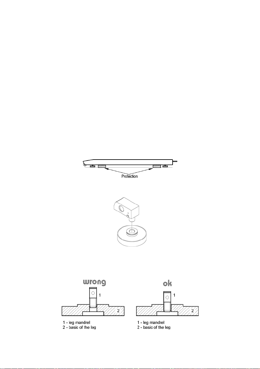
4. UNPACKING AND MOUNTING
Before using the scale remove the transport protections (if installed):
Then screw in levelling feets on the mandrels that protrude from load cells:
Place the scale on the spot of use on the flat, stable ground far away from
sources of heat. The platform should be levelled out by putting pads under
feet and the use of an external level device.
8

Every foot can be screwed in or out. This way only a smal range of level
regulation is achievable. Basic levelling should be performed by putting
steel pads under legs and observing the level on external level device.
5. CONSTRUCTION
5.1. Main dimensions
Dimensions of PUE 7 in plastic casing
Dimensions of PUE 7P with stainless housing
9
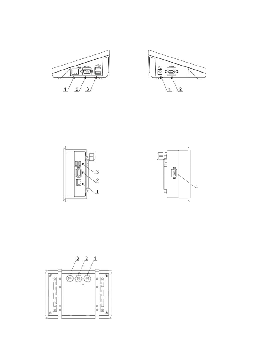
5.2. Description of connectors
5.2.1. Connectors’ description in PUE 7
1 – Ethernet RJ45
2 – RS232 (COM1)
1 – power supply socket
2 – I/O, RS232 (COM2)
3 – USB
5.2.2. Connectors’ description in PUE 7P
1 – Ethernet RJ45
2 – RS232 (COM1)
3 – USB
1 – I/O, RS232 (COM2)
5.2.3. Description of glands PUE 7P
1 – Supply cord gland
2 – Gland for platforms 1, 2
3 – Gland for platforms 3, 4
10
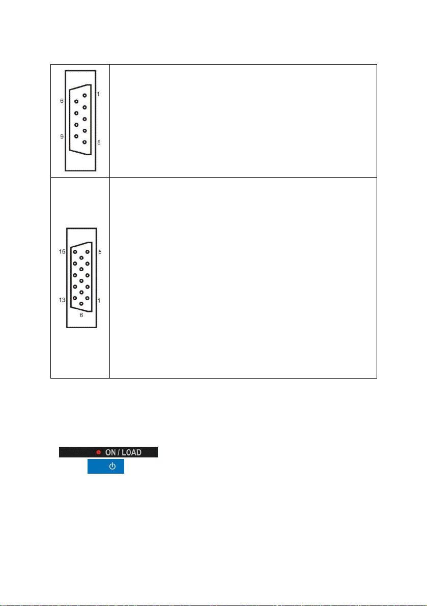
5.2.4. Connector with RS232 and I/O
RS232 - DB9/M (male),
top view:
Pin2 - RxD
Pin3 - TxD
Pin5 - GND
I/O, RS232 DSUB15/F (female),
top view:
Pin1 - GNDWE
Pin2 - OUT1
Pin3 - OUT2
Pin4 - COMM
Pin5 - 6÷9VDC
Pin6 - IN4
Pin7 - IN3
Pin8 - TxD2
Pin9 - 5VDC
Pin10 - GNDRS
Pin11 - IN2
Pin12 - IN1
Pin13 - RxD2
Pin14 - OUT4
Pin15 - OUT3
6. GETTING STARTED
• After the terminal is connected to power the ON/LOAD
diode starts to light.
• Press
Windows CE together with RADWAG software loading is signalled
by blinking the red diode ON/LOAD.
• When the loading procedure is completed the main software
window appears.
to start the operating system loading procedure.
11
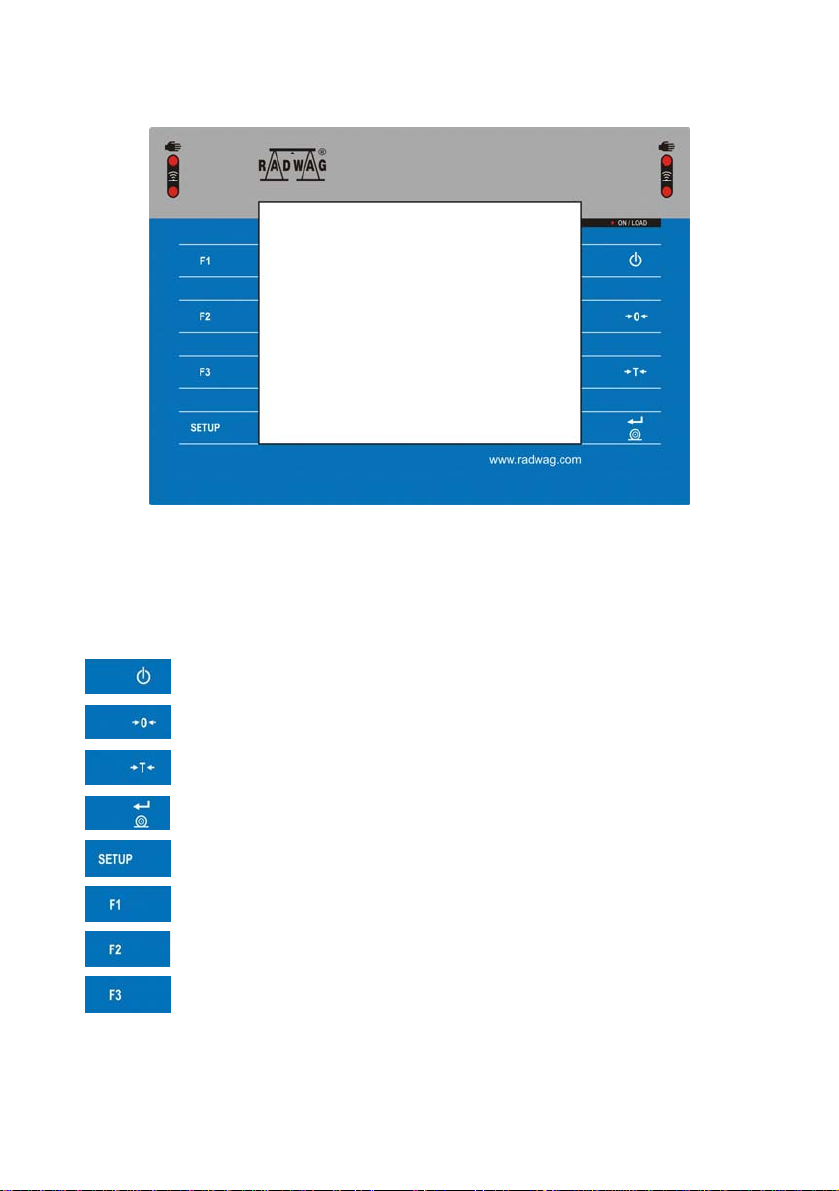
7. KEYPAD OVERLAY
8. FUNCTIONS OF KEYS
Key Description
Turning on/off the scale
Zeroing
Tarring
Printing out the result or confirming some entered data
Function key (entering the menu)
Selecting products
Selecting contractors
Inscribing a tare value
12
9. PROGRAM STRUCTUR E
The main menu has been divided into three functional groups.
In every group there are parameters of similar use.
9.1. Main menu items
The main menu comprises three functional groups:
Parameters
Databases
Info
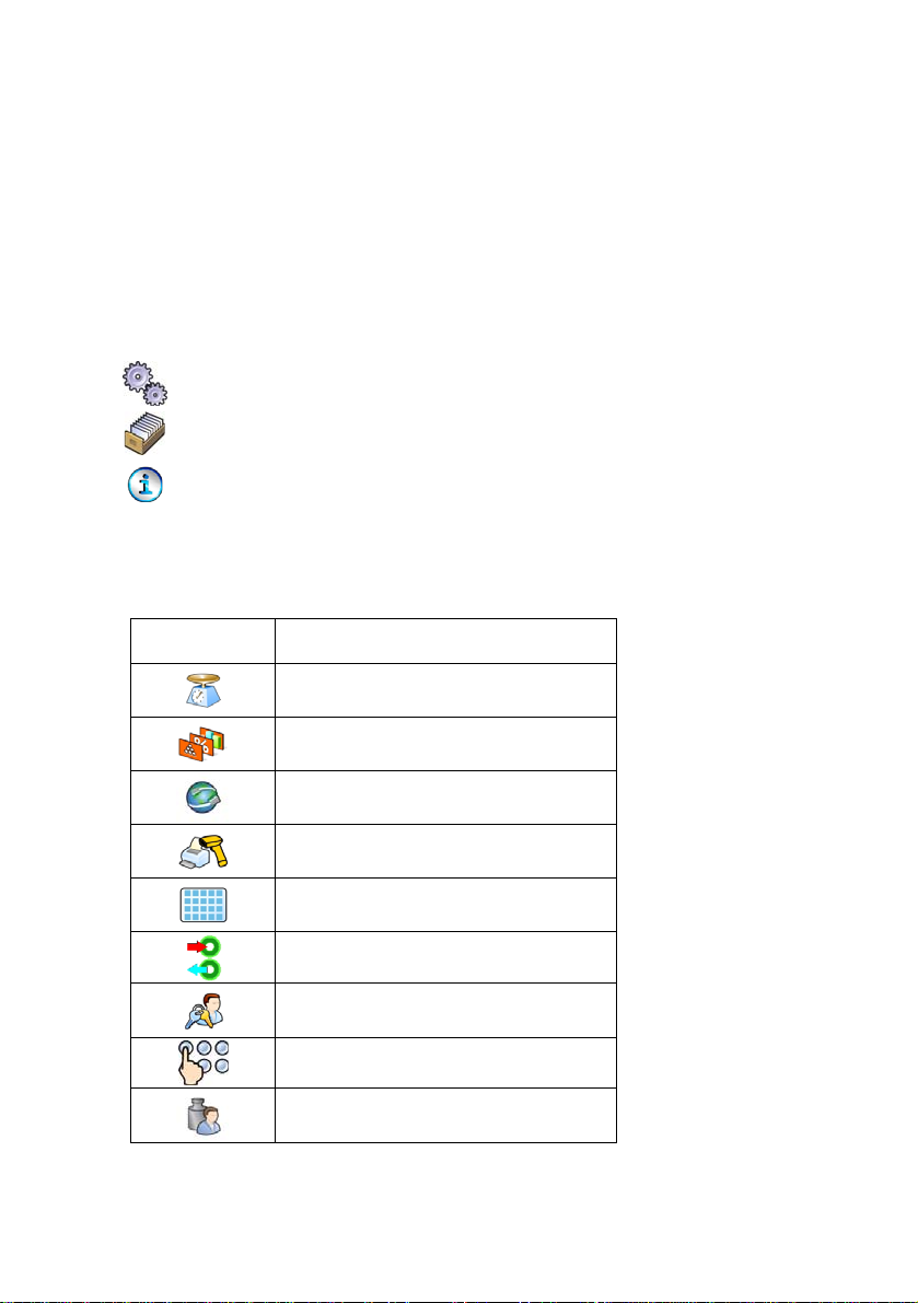
9.1.1. Parameters
Icon Description
Scale
Working Modes
Communication
Devices
Display
Inputs / Outputs
Authorization
Other
User Calibration
13
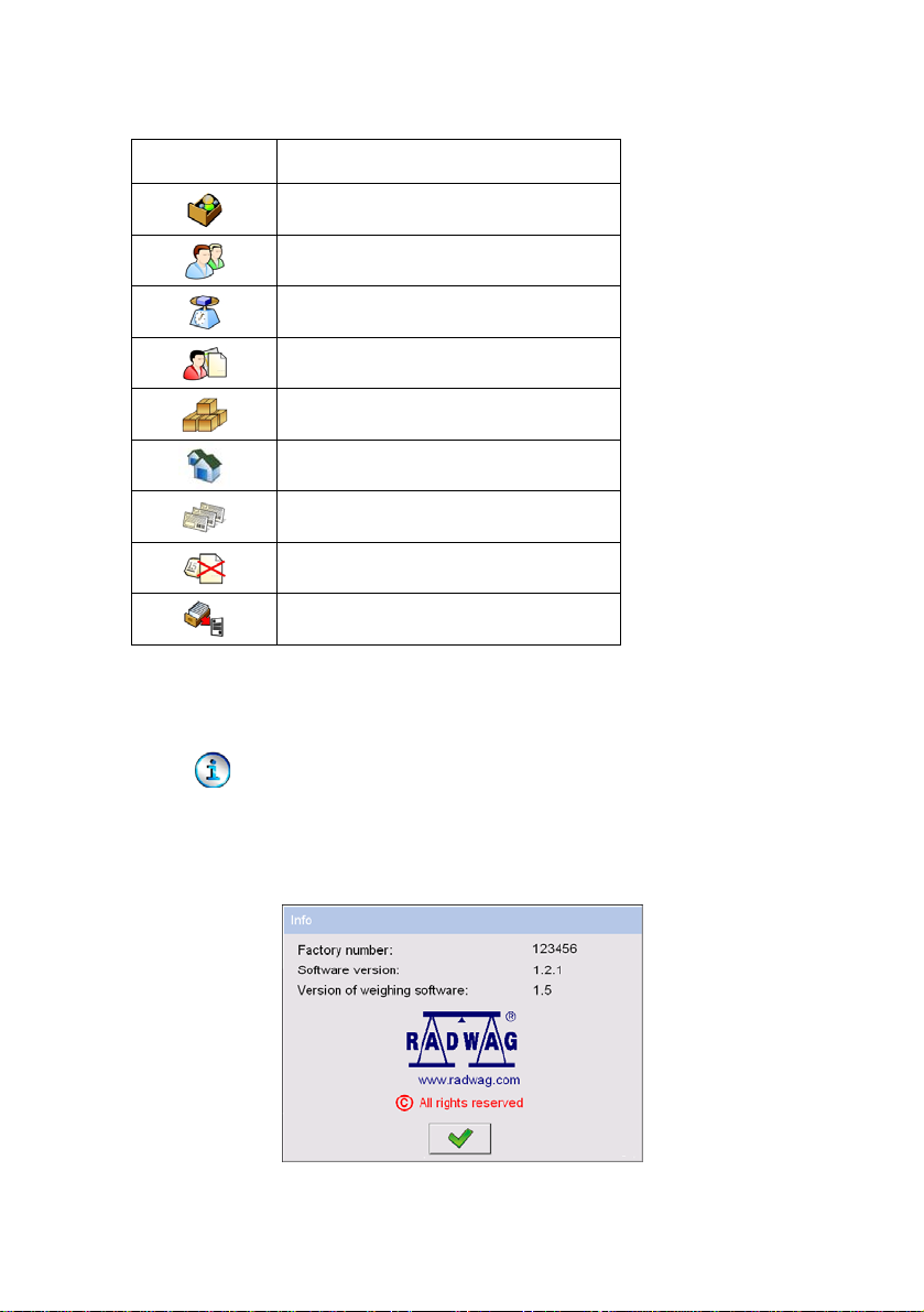
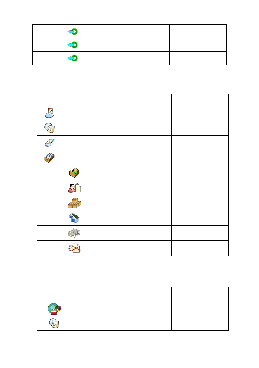
9.1.2. Databases
Icon Description
9.1.3. Scale Info
Products
Operators
Weighings / Alibi
Contractors
Packages
Warehouses
Labels
Delete older data
Export database weighings to a file
Submenu < Info> is for viewing information:
• Scale factory number,
• Program version,
• Scale program version.
14
9.2. Inventory of parameters
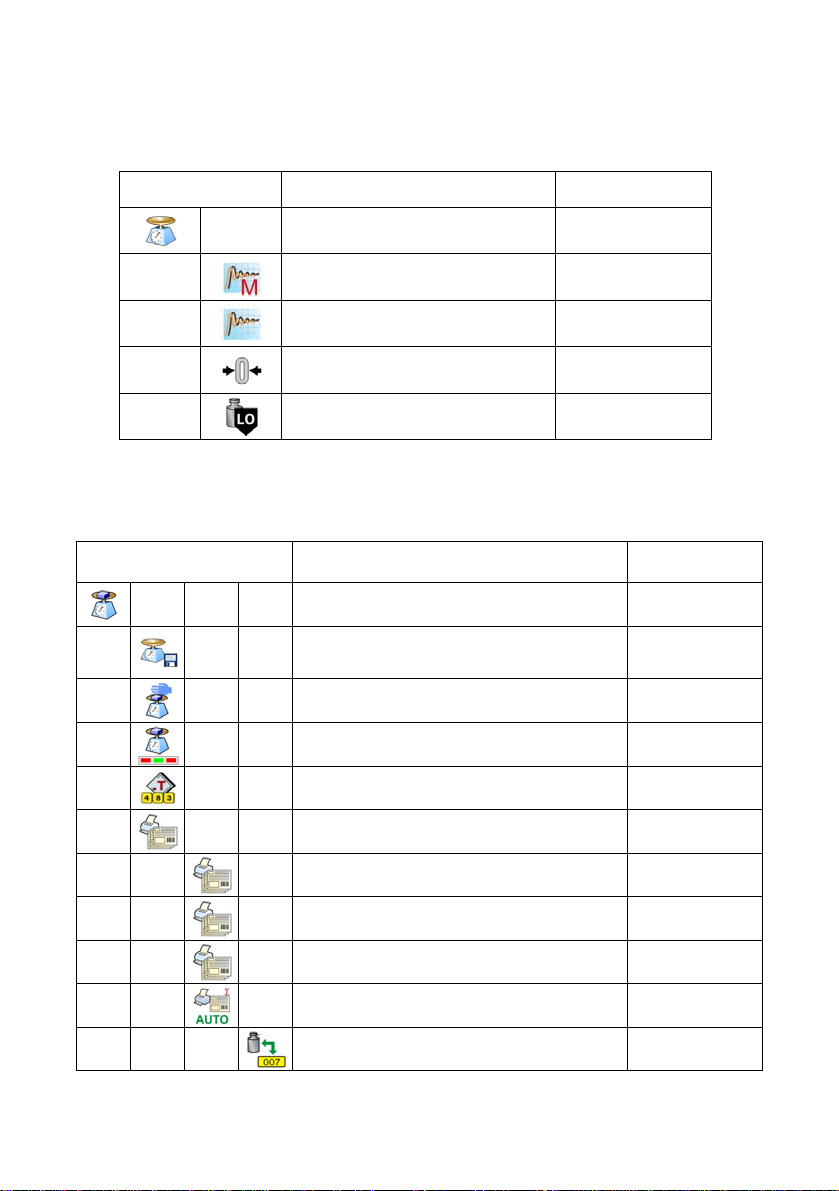
9.2.1. Scale parameters - weighing
Icon Description Value
Platform 1 -
Median Filter 0.5
Filter Fast
Autozero Yes
LO threshold 0
9.2.2. Working modes
Icon Description Value
Weighing -
Save Mode
Down-weighing No
Checkweighing No
Tare mode No
Labelling mode -
Number of labels 1
No. of cumulative labels 1
No. of CC labels 1
C label automatic triggering -
Mode None
Manual, each
stable
15
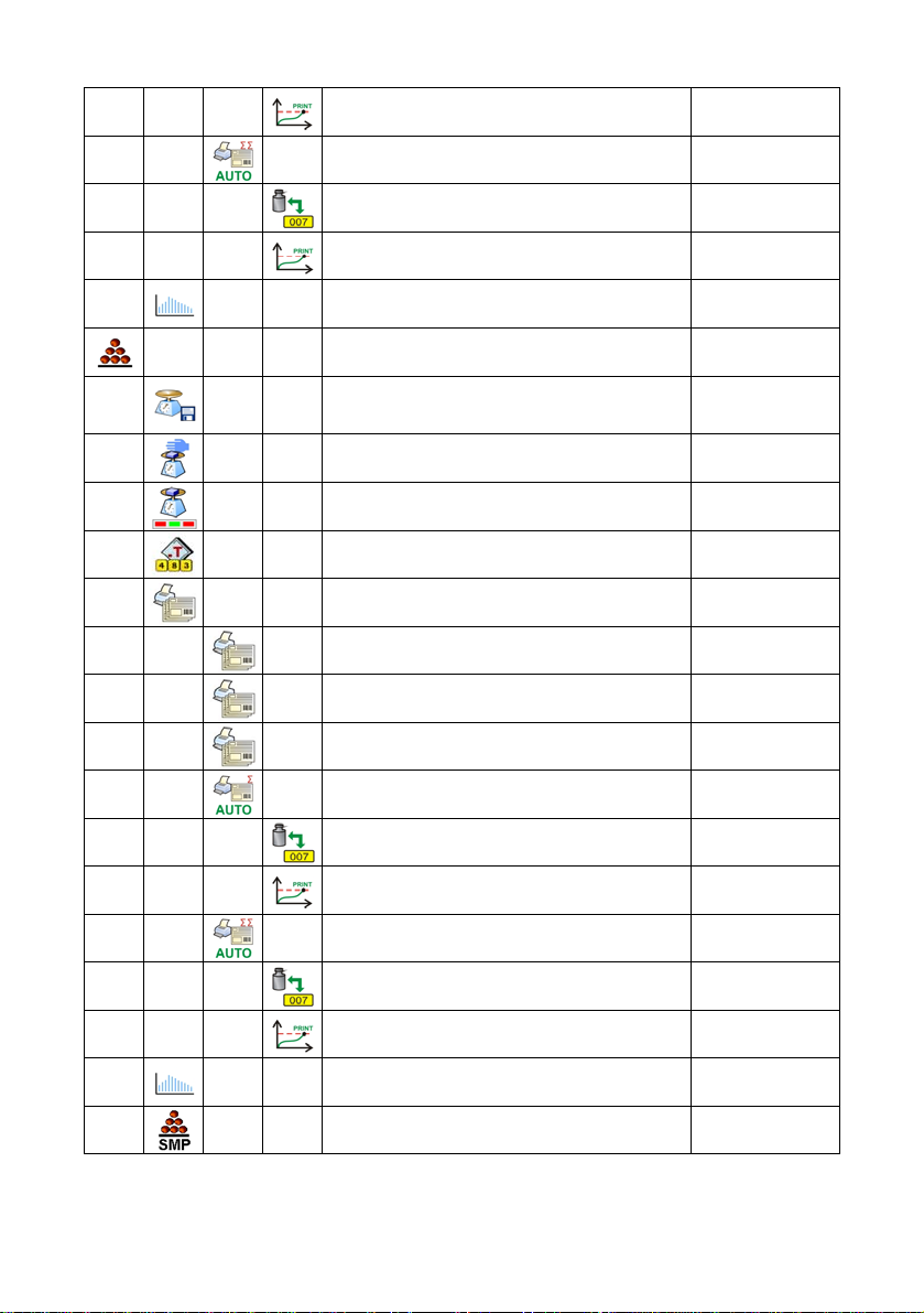
Threshold 100
CC label automatic triggering -
Mode None
Threshold 100
Statistics Global
Counting pieces -
Save Mode
Down-weighing No
Checkweighing No
Tare mode No
Labelling mode -
Number of labels 1
No. of cumulative labels 1
No. of CC labels 1
C label automatic triggering -
Manual, each
stable
Mode None
Threshold 100
CC label automatic triggering -
Mode None
Threshold 100
Statistics Global
Automatic correction of reference mass No
16
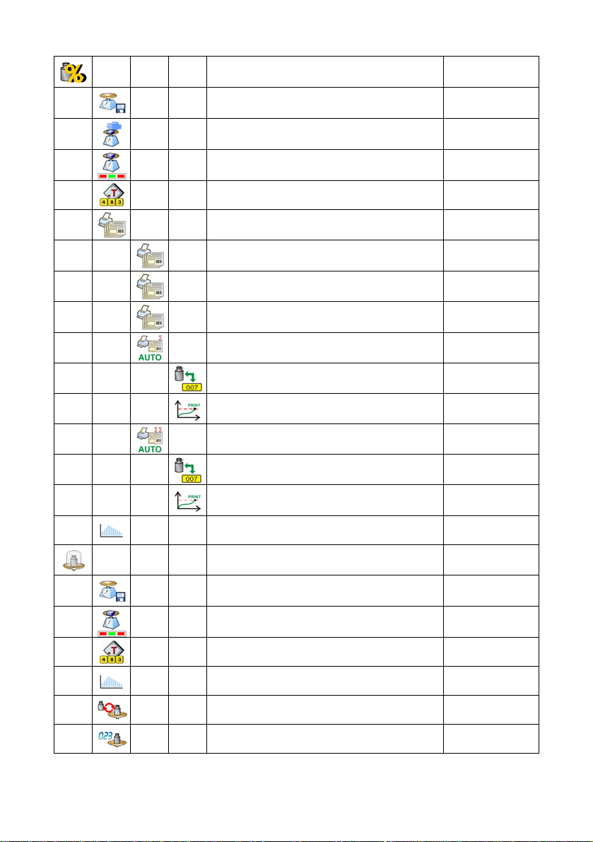
Deviations -
Save Mode
Down-weighing No
Checkweighing No
Tare mode No
Labelling mode -
Number of labels 1
No. of cumulative labels 1
No. of CC labels 1
C label automatic triggering -
Manual, each
stable
Mode None
Threshold 100
CC label automatic triggering -
Mode None
Threshold 100
Statistics Global
Comparator -
Save Mode
Checkweighing No
Tare mode No
Statistics Global
Method ABBA
Number of measurements 10
Manual, each
stable
17
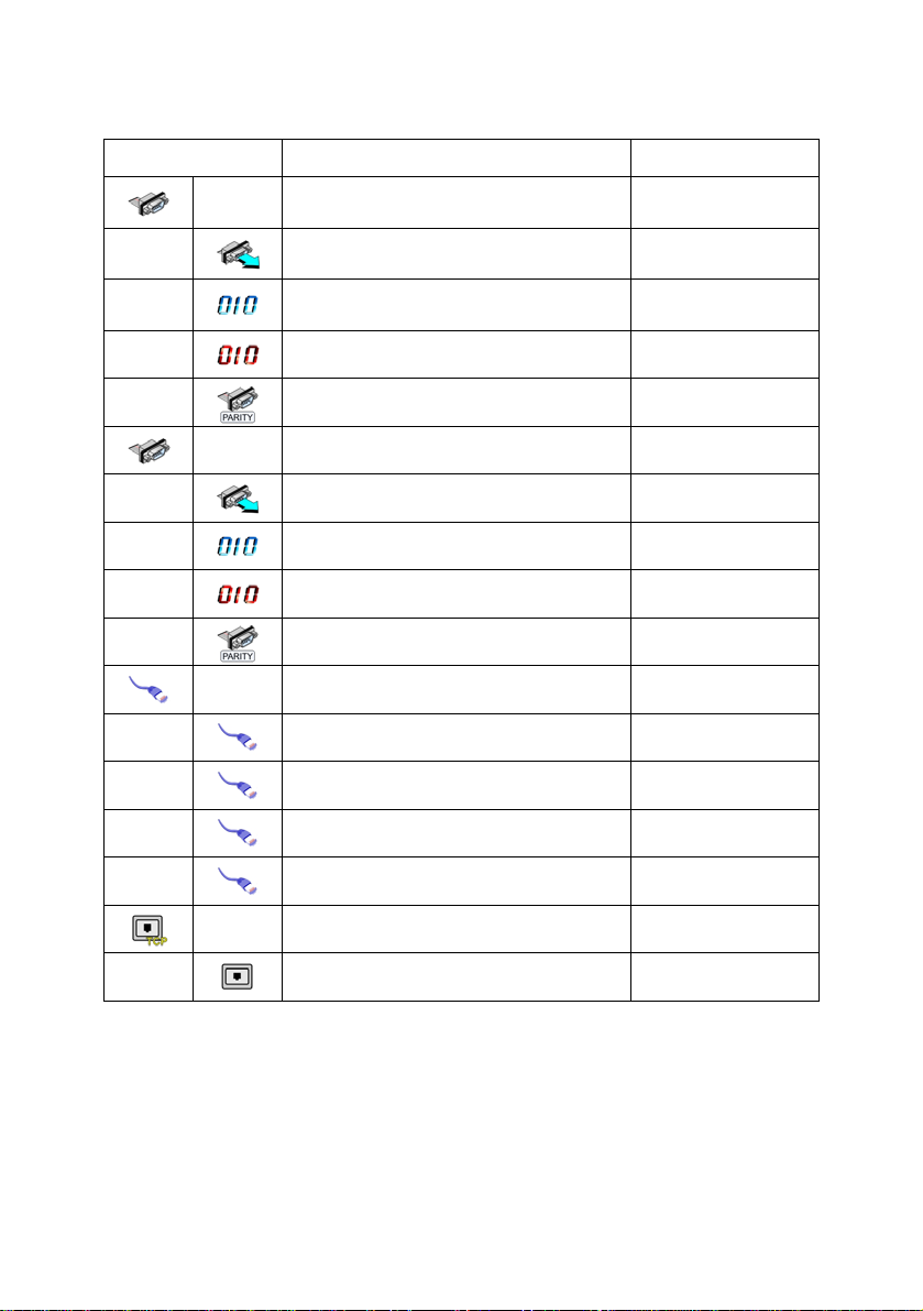
9.2.3. Communication
Icon Description Value
COM1 -
Baud Rate 9600
Data bits 8
Stop bits 1
Parity None
COM2 -
Baud Rate 9600
Data bits 8
Stop bits 1
Parity None
Ethernet -
DHCP No
IP Address 192.168.0.2
Subnet mask 255.255.255.0
Gateway 192.168.0.1
Tcp -
Port 4001
18
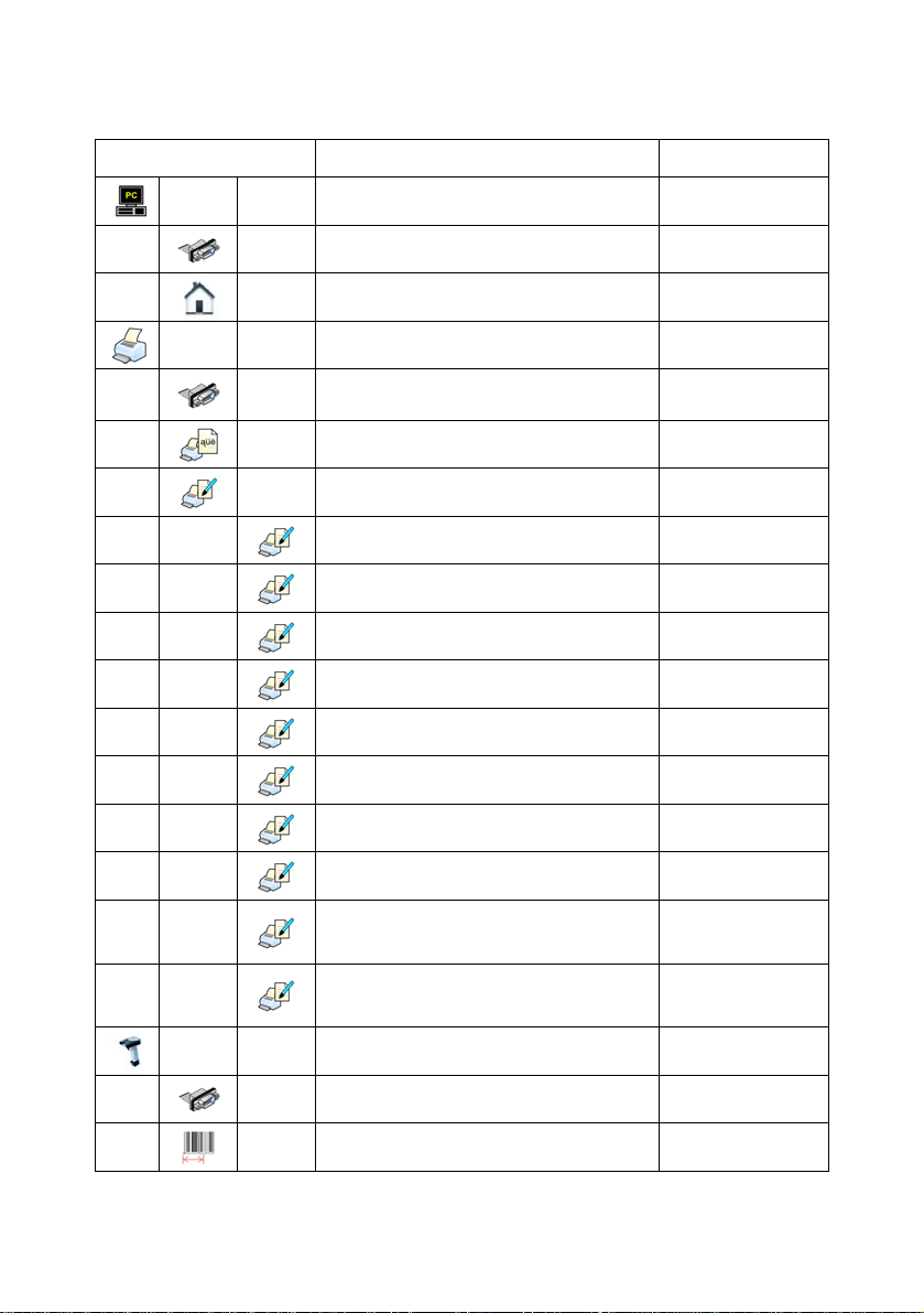
9.2.4. Devices
Icon Description Value
Computer
Port None
Address 1
Printer -
Port COM1
Code page 1250
Printouts -
Weighing printout pattern See ch. 16.2.3
Product printout pattern See ch. 16.2.3
Cumulative printout pattern See ch. 16.2.3
Cumulative printout pattern
for cumulative data
Operator printout pattern See ch. 16.2.3
Contractor printout pattern See ch. 16.2.3
Warehouse printout pattern See ch. 16.2.3
Package printout pattern See ch. 16.2.3
CPG report printout pattern
(Control of Packaed Goods)
Average tare report printout pattern
(Control of Packaed Goods)
See ch. 16.2.3
*
*
Barcode reader -
Port None
Offset 0
19
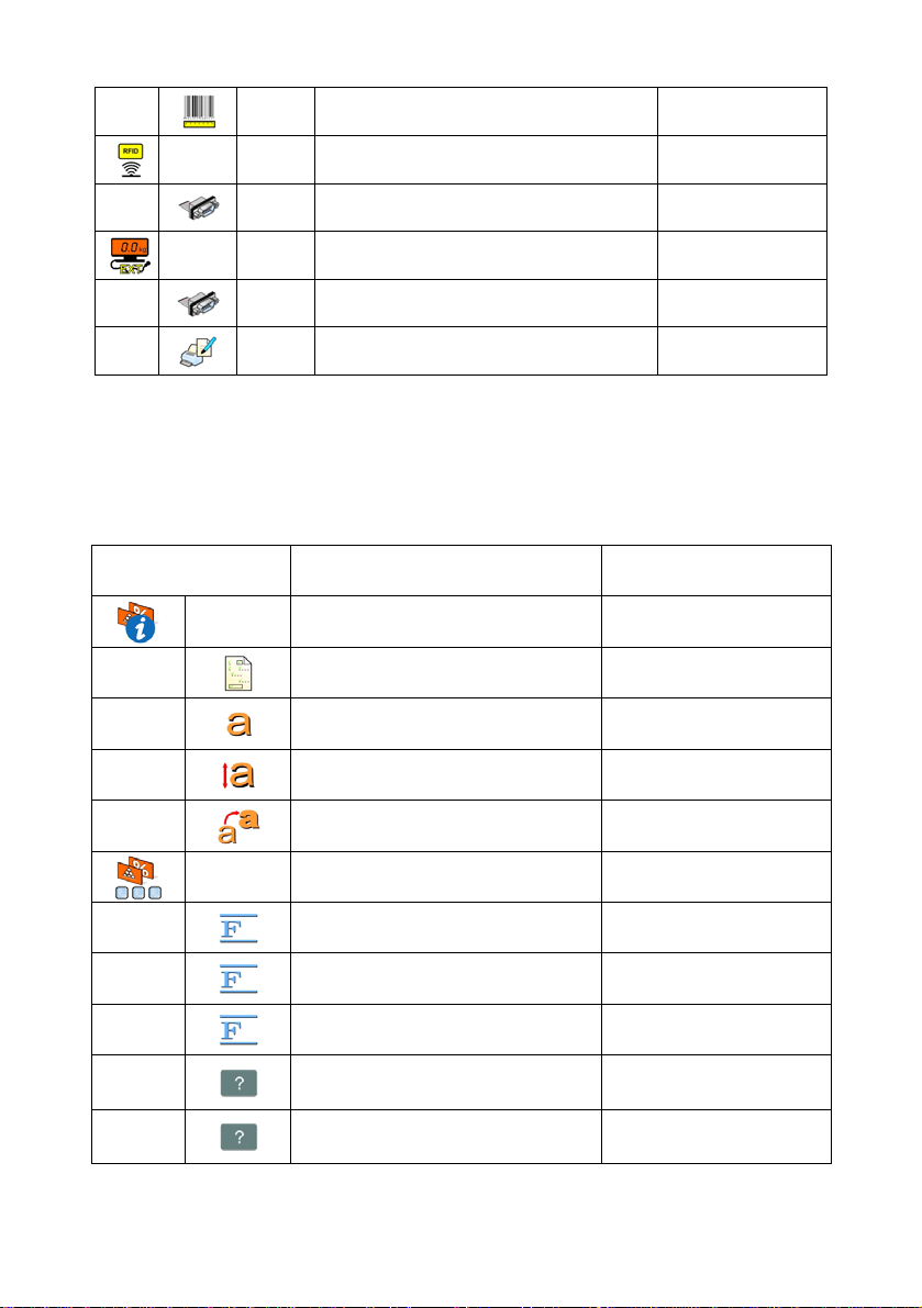
Code length 0
Transponder card reader -
Port None
Additional display -
Port None
Pattern See ch. 16.2.3
*) Not related to „Comparator”.
9.2.5. Display
Icon Description Value
Text information -
Displaying pattern See ch. 17.1.1
Font Arial
Font size Small
Bold No
Actions
F1 Button Choose product
F2 Button Choose contractor
F3 Button Set tare
Screen button 1 Local parameters
Screen button 2 Set MIN and MAX
20
9.2.6. Inputs / Outputs
Icon Description Value
Screen button 3 Statistics C: Print
Screen button 4 CCStatistics : Print
Screen button 5 C Statistics : Zero
Screen button 6 Choose package
Screen button 7 Edit batch number
Screen button 8 None
Screen button 9 None
Left proximity sensor None
Right proximity sensor None
Set Default -
Show all platforms No
Bargraph type None
Inputs -
Input 1 None
Input 2 None
Input 3 None
Input 4 None
Outputs -
Output 1 None
21
9.2.7. Authorizations
Icon Description Value
9.2.8. Other
Icon Description Value
Output 2 None
Output 3 None
Output 4 None
Anonymous operator Operator
Date & Time Administrator
Printouts Administrator
Databases
Products Administrator
Contractors Administrator
Packages Administrator
Warehouses Administrator
Labels Administrator
Delete older data Advanced Operator
Language Polish
Date & Time -
22
Beep Buttons
Touch screen calibration -
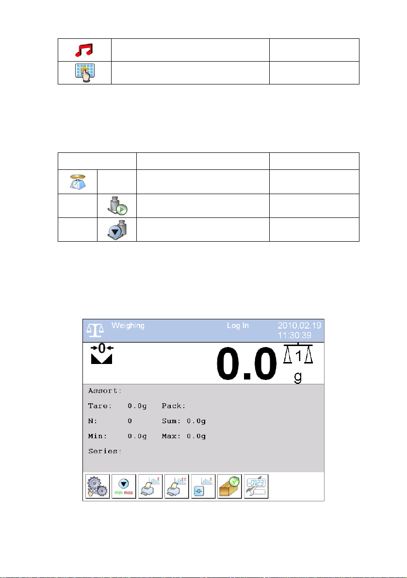
9.2.9. User Calibration
Icon Description Value
Platform 1 -
Setting of start mass -
Calibration -
10. INDICATIN G WINDOW
Main view:
An option only for non-verified scale
23
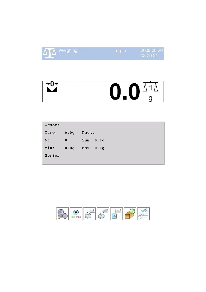
In the main application window one can see four separate parts:
• In the top part of the window there is a status bar where a work mode,
logged-in user and time&date are displayed.
• Below the status bar you can see weighing window(s).:
• There is a workspace below this window:
Notice:
The workspace is freely programmable. The default pattern is
described in ch. 17.1.1 of this manual.
• There are screen buttons below the workspace:
Notice:
1. Users can define screen function buttons. See the procedure
in ch. 17.2 of this manual;
2. The number of buttons to be defined depends on the selected
operating mode i.e.:
24

• In operating mode <Weighing> 9buttons are at ones disposal
displayed subsequently from 1 to 9 starting from the left side,
• In operating modes: <Counting pieces> or <Deviations> one
can define up to 7 screen buttons displayed subsequently from
1 to 7 starting from the left side. Two buttons on the right side
are attributed permanently to the modes mentioned above
because of the functions that are ascribed to them.
11. LOGGING ON
In order to have full access to user parameters and databases the user
should log on as an <Administrator>.
11.1. Logging in procedure
• While in the main window press <log in> on the top of the screen
and the window with operators attributed to <
• After entering <
Admin> a screen keyboard runs with editing
Admin> will appear,
window for inscribing a password,
• Type password „1111” and confirm by pressing
,
• The program returns to the main window and in the title bar you will
see <Admin> instead of <log in>.
11.2. Logging out procedure
• While in the main applilcation window press the name of a logged in
operator in the top bar on the screen to open the database of operators,
• Press logging out button situated in the top bar of the operators’
database window:
• The program returns to the main window and in the top bar the
operators name is substituted by <Log in>.
25

11.3. Authorization access levels
Weighing software uses four access levels: administrator, advanced
operator, operator, none. Every user with any attributed access level
can perform weighings and select data from in databases to be used
during weighing.
Access to user parameters, databases and working modes depending
on the authorization access level attributed:
Operator type Access level description
None
No access to user parameters. Cannot start procedure
„Comparison”. Cannot enter the reference mass unit and
estimate the reference mase unit by weiging in „Counting Pieces”
Operator
and „Deviations”. No access to <Export the weighing database
to a file> in menu <Databases>
Access to parameters in submenu: <Weighing>, <Display>
(excluding the group <Actions>), <Others>
2)
.
1)
. Can start and
perform all weighing procedures. Access to <Export the
weighing database to a file> in menu <Databases>
Advanced
Operator
Administrator
Access to parameters in submenus: <Weighing>, <Working
modes>, <Communication>, <Devices>
<Others>
Access to <Export the weighing database to a file> in menu
<Databases>
1)
. Can start and perform all weighing procedures.
2)
.
1)
, <Display>1),
Access to all user parameters, functions and databases
Can start and perform all weighing procedures.
1. Authorization level for editing functions:
• < Printouts> in submenu „ Devices / Printer”,
• <
Sample> in submenu „ Devices /
Additional display”,
1)
2)
.
2)
.
• <
• <
Displaying pattern> in submenu „ Display /
Text information”,
Date and Time> in submenu < Others>,
26
It can be declared in submenu < Authorizations>, which is
accessable only for users with the <Administrator> authorization
level (see ch. 19 of this manual).
2. A user logged in as <Administrator> in submenu
<
Authorizations> (see ch. 19 of this manual) can change
authorization levels for accessing different databases and functions
Delete older data>. The exception are database
<
<
Weighings / Alibi>, that have the status „Read only”.
12. NAVIGATING WITHIN THE MENU
Owing to the colour display with the touch panel navigating within the menu
is simple and intuitive.
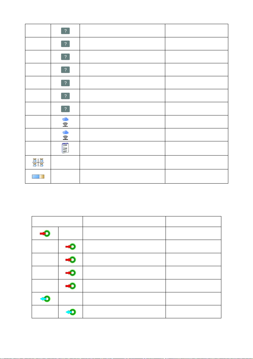
12.1. Buttons
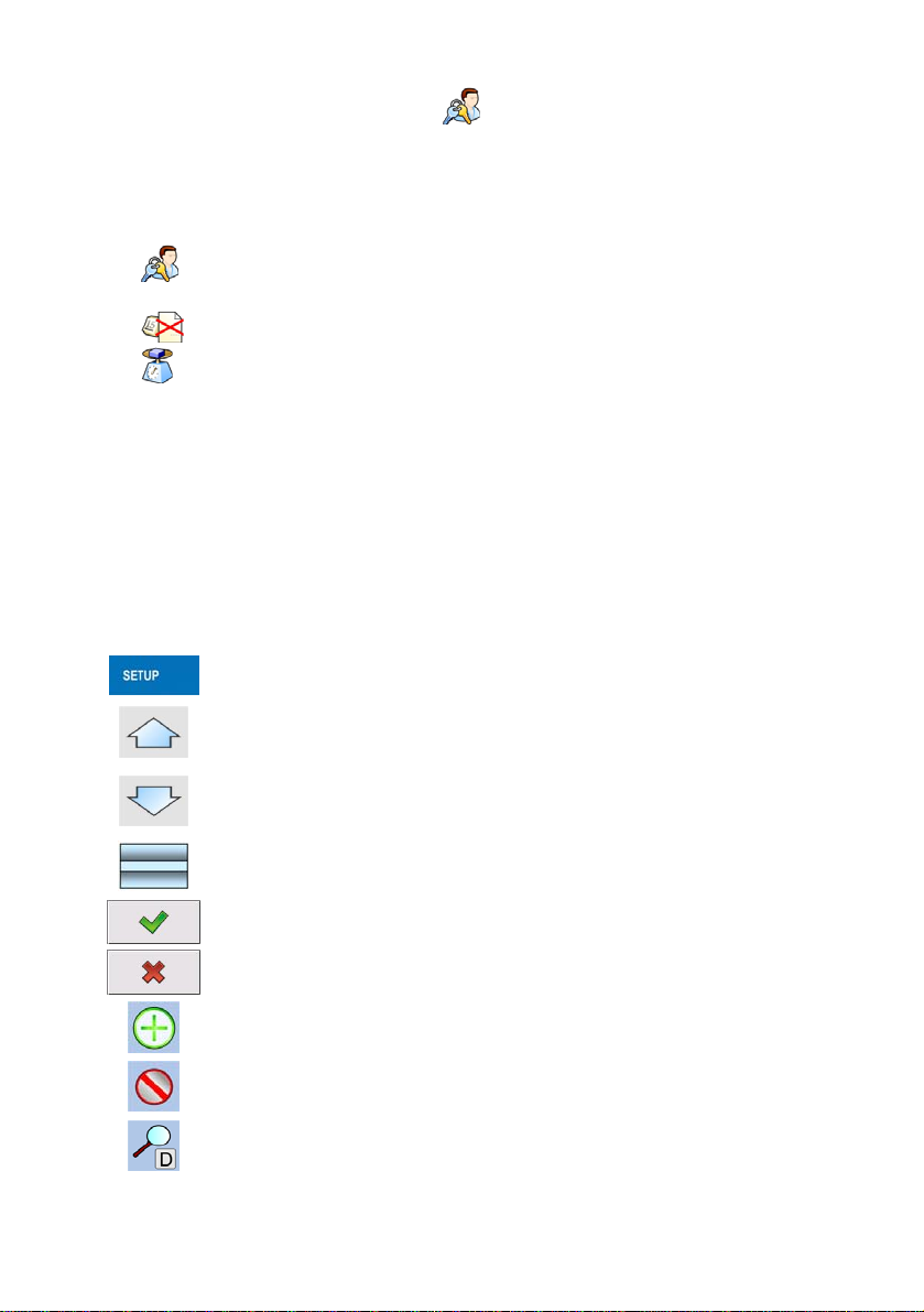
Entering the main menu
Menu list „up”
Menu list „down”,
Scrolling „up-down”
Enter (OK)
Abort
Add a new item in a database
Disabeling the formerly selected record e.g. logging out the operator
Searching a database according to a date
27
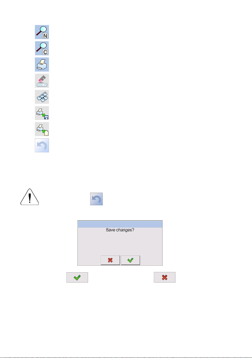
Searching a database according to a name
Searching a database according to a code
Printing on item from a database
Clearing an editing field
Screen keyboard on / off
Reading a printout pattern from a *.lb file
(active after connecting a pendrive)
Variables for a printout pattern
One level up
12.2. Return to weighing
The changes introduced are saved for good after they are
confirmed. Press
several times until the following
message box appears:
Press:
– to confirm changes or – to abort
changes. The program returns to weighing.
28
13. WEIGHING
Put a load on the weight pan. When pictogram
indication is ready to read.
Notice:
A weighing can be saved after stabilising a measurement over zero
(pictogram
).
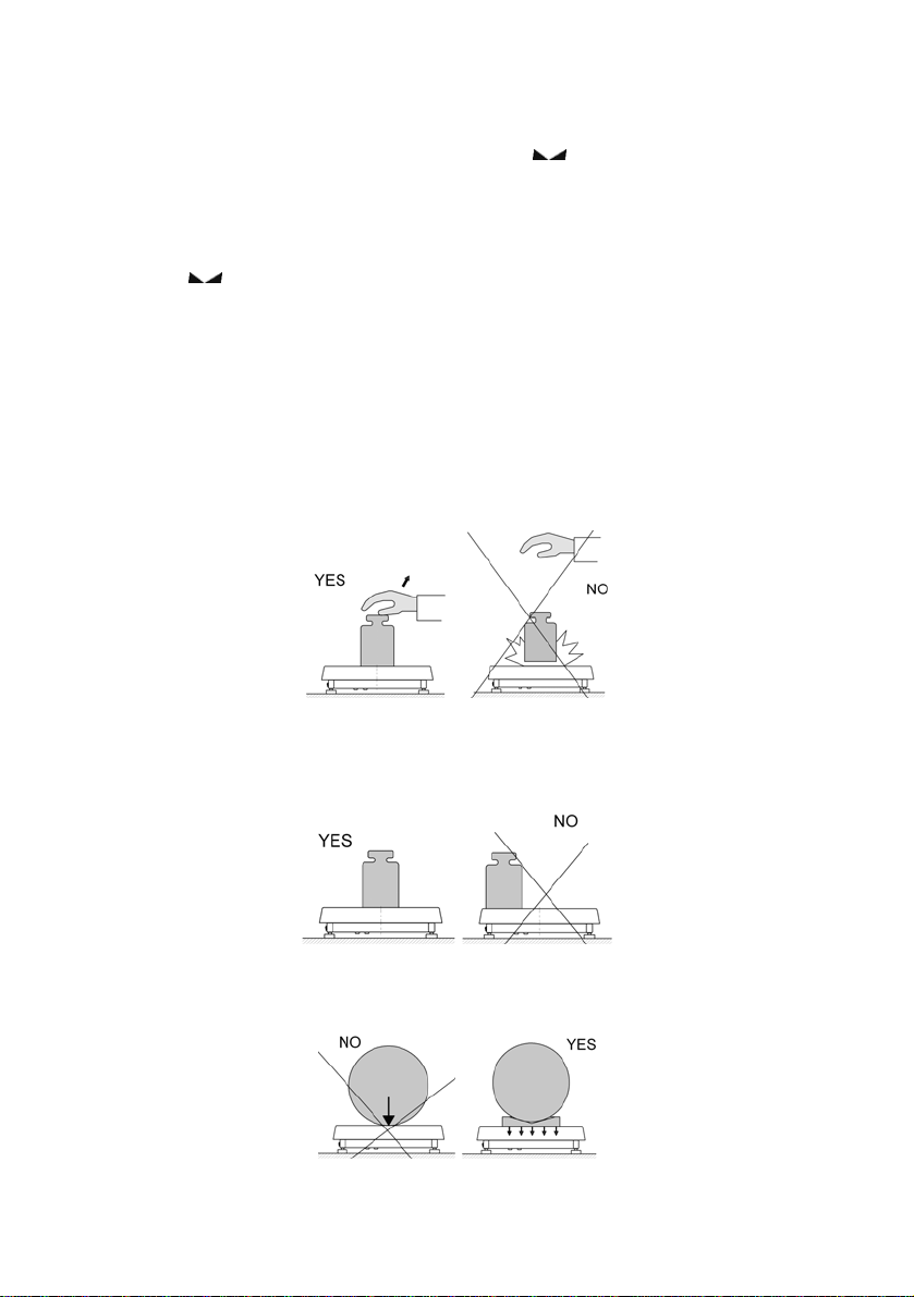
13.1. Conditions of operational use
In order to assure a long term operating period with appropriate
measurements following principles should be adhered to:
• Avoid applying mechanical shocks to the weight pan:
is displayed the
• Loads should be placed in the centre of the pan (eccentric errors
are outlined in PN-EN 45501 chapter 3.5 and 3.6.2):
• Do not apply concentrated forces (all load in one point):
29
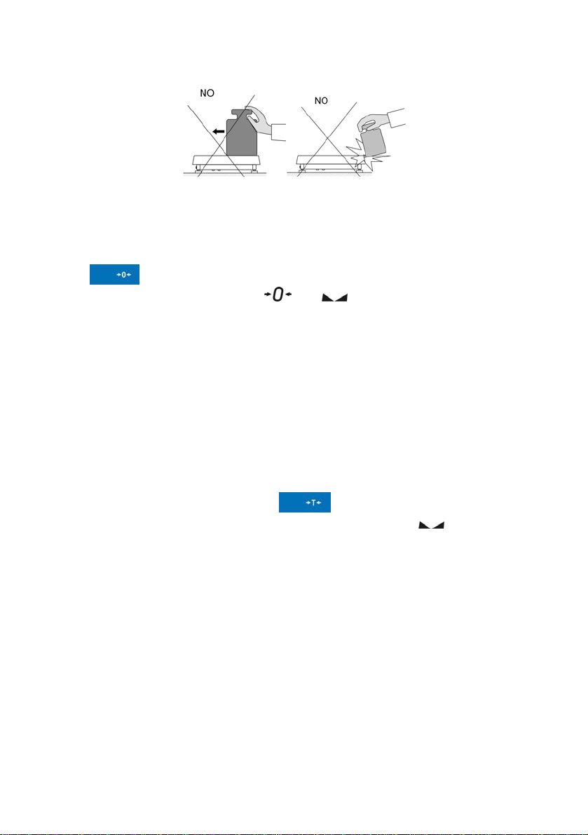
• Avoid side loads, particularly side strokes:
13.2. Zeroing
In order to zero the indication choose a platform on the touch panel and
press
following symbols usually appear:
Zeroing is possible only when the indication is stable.
Notice:
Zeroing is possible only within ±2% of full range around zero. If the
zeroed value is beyond the interval of ±2%, Err2 is displayed.
13.3. Tarring
In order to tare the scale choose a platform on the touch panel if necessary,
put a package on the pan and press
equal zero and following symbols usually appear:: Net and
After placing a load on the weight pan net mass will be shown. Tarring is
possible within the whole range of the scale. After unloading the pan the
display shows the tarred value with minus sign.
You can also inscribe tare values to the assortment database. Every product
has a field “Tare”. In that case tare is automatically set to this value after
selecting the product.
Notice:
Tarring cannot be performer when a negative or zero value is being
displayed. In such case Err3 appears on the display.
. After zeroing is performed the indication is equal zero and
and .
. You will see the indication
.
30
 Loading...