

Page 1

Manual number:
ITKU-10-03-11-11-A
WPW/T scales for fast loads control
WPW Multifunctional scales
WPW/D dosing scales
MANUFACTURER OF ELECTRONIC
WEIGHING INSTRUMENTS
RADWAG 26 – 600 Bracka 28 Street - POLAND
Radom, phone +48 48 384 88 00, phone/fax +48 48 385 00 10,
Sales Department +4848 366 80 06
www.radwag.com
Page 2

NOVEMBER 2011
- 2 -
Page 3

Table OF CONTENTS
1. NTENDED USE .......................................................................................................................................7 I
2. PRECAUTIONARY MEASURES..............................................................................................................8
2.1. recautions......................................................................................................................................8 P
ccumulator / battery pack ..............................................................................................................8 A
2.2.
O
2.3. peration in a strong electrostatic field............................................................................................9
2.4. Washing scales intended for meat processing industry ...................................................................9
3. WARRANTY CONDITIONS....................................................................................................................11
4. MAIN DIMENSIONS ...............................................................................................................................12
5. DESCRIPTON OF CONNECTORS.........................................................................................................12
6. UNPACKING AND MOUNTING..............................................................................................................13
7. GETTING STARTED ..............................................................................................................................13
8. KEYBOARD............................................................................................................................................14
9. PICTOGRAMS........................................................................................................................................14
9.1. Battery charge indication ...............................................................................................................15
10. UCTIONS OF KEYS............................................................................................................................15 F
11. MENU - PARAMETERS........................................................................................................................16
11.1. verview of parameters...............................................................................................................16 O
Navigating within the menu level..................................................................................................20
11.2.
11.2.1. eyboard...........................................................................................................................20 K
1 .2.2. Quick access.....................................................................................................................211
11.3. Return to weighing.......................................................................................................................21
12. WEIG ING............................................................................................................................................22H
12.1. perating conditions....................................................................................................................22 O
12.2. arring.........................................................................................................................................23 T
12.3. nscribing tare value.....................................................................................................................23 I
eroing........................................................................................................................................24 Z
12.4.
W
12.5. eighings in two ranges..............................................................................................................25
12.6. Toggling between weight units.....................................................................................................25
12.6.1. election of basic unit........................................................................................................25 S
1 .6.2. Toggling between weight units...........................................................................................262
12.7. Switching between platforms .......................................................................................................26
13. MAIN ARAMETERS............................................................................................................................27P
13.1. iltering level ...............................................................................................................................27 F
edian filter.................................................................................................................................28 M
13.2.
D
13.3. osing filter setting......................................................................................................................28
13.4. inimal mass parameter .............................................................................................................30 M
13.5. are function................................................................................................................................31 T
13.6. Autozero......................................................................................................................................32
14. PORTS PARAMETERS.........................................................................................................................33
14.1. RS 232, RS 485 setting ...............................................................................................................33
14.1.1. aud rate of RS 232..........................................................................................................33 B
aud rate of RS 485..........................................................................................................34 B
14.1.2.
R
14.1.3. S 232 parameters ...........................................................................................................35
1 .1.4. Setting of RS 485 parameters ...........................................................................................364
14.2. ETHERNET setting...................................................................................................................... 37
15. EXTERNAL DEVICES...........................................................................................................................38
15.1. Cooperation with a computer.......................................................................................................38
15.1.1. elect the communication port scale-computer .................................................................38 S
15.1.2. ype of printout scale – computer......................................................................................39 T
ddress setting..................................................................................................................40 A
15.1.3.
rder operating of communication protocol.......................................................................40 O
15.1.4.
Cooperation with „E2R System”......................................................................................... 41
15.1.5.
15.1.5.1. stem” ..............................................................................................41 Enabling „E2R Sy
15.1.5.2. eighings....................................................................................................42 Buffer for w
15.1.5.3. The lock of product change........................................................................................43
15.2. Cooperation with printers.............................................................................................................43
1 .2.1. Communication port scale - printer....................................................................................43 5
Cooperation with a barcode scanner ...........................................................................................44
15.3.
- 3 -
Page 4

15.3.1. elect a communication port for the scanner.....................................................................44 S
15.3.2. etting the START parameter............................................................................................45 S
1 .3.3. Setting the LENGTH parameter.........................................................................................465
15.4. Cooperation with a transponder card reader................................................................................46
15.4.1. electing of communication port........................................................................................47 S
1 .4.2. Procedure of ascribing card numbers to operators............................................................475
15.5. Cooperation with an additional display.........................................................................................48
15.5.1. electing a communication port.........................................................................................48 S
15.5.2. Selecting an additional display type ...................................................................................49
16. DATE TIME SETTING.........................................................................................................................50 /
16.1. ime view ....................................................................................................................................50 T
16.2. ime setting.................................................................................................................................50 T
16.3. Date format..................................................................................................................................51
17. PRINTOUTS..........................................................................................................................................52
17.1. rintout type ................................................................................................................................52 P
rintout of stable / unstable data .................................................................................................53 P
17.2.
C
17.3. heckweighing mode ..................................................................................................................54
17.4. on-standard printouts................................................................................................................55 N
17.5. esigning non-standard printouts................................................................................................55 D
17.6. Texts in non-standard printouts ...................................................................................................56
17.6.1. ode format.......................................................................................................................56 C
17.6.2. ariables appearing in all modes .......................................................................................57 V
17.6.3. ariables for printing out weighings from the database .....................................................58 V
17.6.4. ariables for printouts of reports from weighings...............................................................59 V
17.6.5. Special characters that can be used in non-standard printouts .........................................60
18. DATA ASES.........................................................................................................................................60B
18.1. ogging in....................................................................................................................................60 L
18.2. Access level................................................................................................................................. 62
18.2.1. ccess level to edition of databases..................................................................................62 A
1 .2.2. Access level for disabled logging.......................................................................................628
18.3. assword type.............................................................................................................................63 P
18.4. ype of codes..............................................................................................................................64 T
18.5. ccess to edition of databases....................................................................................................65 A
Quick searching in databases......................................................................................................65
18.6.
18.6.1. uick code search .............................................................................................................66 Q
18.6.2. uick name search............................................................................................................66 Q
1 .6.3. Quick number search ........................................................................................................678
18.7. ser database.............................................................................................................................68 U
18.8. ssortment database...................................................................................................................70 A
18.9. Weighings database ....................................................................................................................72
18.10. alues.............................................................................................................73 Database of tare v
18.11. General purpose variables.........................................................................................................74
18.11.1. diting general purpose variables ...................................................................................74 E
General purpose variables in printouts ............................................................................75
18.11.2.
19. REPORTS FROM WEIGHINGS............................................................................................................76
19.1. diting reports .............................................................................................................................76 E
19.2. Printouts of reports ......................................................................................................................77
20. CONF GURATION OF EXTERNAL INPUTS / OUTPUTS.....................................................................78I
20.1. onfiguration of external buttons.................................................................................................78 C
20.2. Configuration of outputs...............................................................................................................79
21. STATI TICS..........................................................................................................................................80S
21.1. pdating statistics .......................................................................................................................80 U
21.2. rintouts of statistics....................................................................................................................81 P
21.3. Zeroing statistics..........................................................................................................................82
22. OTHER PARAMETERS ........................................................................................................................83
22.1. anguage setting .........................................................................................................................83 L
ED power setting ....................................................................................................................... 84 L
22.2.
W
22.3. ork modes for LEDs .................................................................................................................84
22.4. utomatic power down ................................................................................................................86 A
22.5. Backlight......................................................................................................................................87
22.5.1. Backlight – power supply from mains ................................................................................87
- 4 -
Page 5

2 .5.2. Backlight - power supply from the accumulator ................................................................882
22.6. Beep” sound – key-press reaction..............................................................................................88 “
22.7. eypad modes.............................................................................................................................89 K
22.8. Software version view..................................................................................................................90
23. SCAL CALIBRATION .........................................................................................................................90E
23.1. alibration procedure ..................................................................................................................91 C
23.2. Start mass adjustment.................................................................................................................92
24. WORK MODES.....................................................................................................................................93
24.1. ccessibility of work modes.........................................................................................................93 A
24.2. rogrammable keys.....................................................................................................................94 P
24.3. /- control according to an inscribed standard mass....................................................................96 +
24.4. aximal force latch......................................................................................................................98 M
24.5. Counting pieces........................................................................................................................... 98
24.5.1. nabling work modes ........................................................................................................99 E
24.5.2. etting standard mass by inscribing the mass of a single piece........................................99 S
Setting the standard mass by declaring the quantity of a sample....................................100 4
2 .5.3.
Deviation in percents in relation to a standard mass..................................................................101
24.6.
24.6.1. tarting weighing in per cents..........................................................................................101 S
24.6.2. eighing a standard mass..............................................................................................101 W
2 .6.3. Inscribing a standard mass..............................................................................................1024
24.7. Weighing animals ......................................................................................................................103
24.7.1. eighing time setting......................................................................................................103 W
24.7.2. tarting the work mode....................................................................................................104 S
2 .7.3. Procedure of weighing animals........................................................................................1044
24.8. Dosin .......................................................................................................................................105 g
25. IAGRAMS OF CONNECTION CABLES...........................................................................................113 D
26. CONNECTORS ...................................................................................................................................115
26.1. IN/3OUT connector..................................................................................................................115 3
26.2. RS232, RS485 connector..........................................................................................................116
27. SPECIFICATION OF ADDITIONAL MODULES..................................................................................117
27.1. Ethernet module - ET.................................................................................................................118
27.2. Module of Analogue Outputs .....................................................................................................121
27.3. Relay odule - PK1...................................................................................................................125 m
27.4. WE 4 - 4 inputs / 4 outputs module............................................................................................127
27.5. WE 8 - 8 inputs / 8 outputs module............................................................................................129
osing mode setting........................................................................................................105 D
24.8.1.
T
24.8.2. ime interval between changing dosage thresholds........................................................106
24.8.3. ime interval completing process....................................................................................106 T
24.8.4. ode for OUTPUTS ........................................................................................................107 M
24.8.5. arring mode setting........................................................................................................108 T
24.8.6. Corrections......................................................................................................................108
24.8.6.1. .......................................................................................................109 Correction mode
24.8.6.2. alue...............................................................................................109 Initial correction v
24.8.6.3. imum correctional value.....................................................................................110 Max
24.8.6.4. Averaging from subsequent dosing cycles...............................................................111
24.8.7. Starting work modes........................................................................................................112
27.1.1. ounting way in PUE C41H ............................................................................................119 M
2 .1.2. Drawings of sockets and cables for Ethernet...................................................................1217
27.2.1. echnical specification ....................................................................................................122 T
27.2.2. he way of installing inside PUE C41H...........................................................................122 T
27.2.3. onfiguration of work modes of analogue modules .........................................................123 C
2 .2.4. Connections to AN module..............................................................................................1247
echnical specification ....................................................................................................125 T
27.3.1.
I
27.3.2. nstalling in PUE C41H indicators....................................................................................125
2 .3.3. Drawing of cables and outputs ........................................................................................1277
27.4.1. echnical specification ....................................................................................................127 T
27.4.2. olours of cables for I/O..................................................................................................128 C
2 .4.3. Installing method in PUE C41H indicators .......................................................................1287
27.5.1. echnical specification ....................................................................................................130 T
27.5.2. nstalling method in PUE C41H indicators.......................................................................130 I
I/O diagram......................................................................................................................131
27.5.3.
- 5 -
Page 6

2 .5.4. Description of input output wires......................................................................................1327
27.6. DP1 – module for an additional platform....................................................................................132
27.6.1. echnical specification ....................................................................................................133 T
27.6.2. olours of wires...............................................................................................................133 C
27.6.3. onnecting additional platforms.......................................................................................134 C
2 .6.4. Installing in PUE C41H housing .......................................................................................1367
27.7. RS485 led out via RS 1D gland .................................................................................................138
27.7.1. nstalling inside the PUE C41H housing ..........................................................................138 I
27.7.2. RS 485 - PT0012 cable drawing......................................................................................139
28. COMMUNICATION PROTOCOL ........................................................................................................140
28.1. eneral information ...................................................................................................................140 G
28.2. set of commands for RS interfaces ........................................................................................140 A
28.3. espond message format..........................................................................................................141 R
28.4. Command’s description .............................................................................................................141
28.4.1. eroing............................................................................................................................141 Z
28.4.2. arring.............................................................................................................................142 T
28.4.3. et tare value..................................................................................................................142 G
et tare value ..................................................................................................................143 S
28.4.4.
S
28.4.5. end the stable result in basic unit..................................................................................143
28.4.6. end the result immediately in basic unit.........................................................................144 S
28.4.7. et immediate results from both platforms in basic units.................................................144 G
28.4.8. end the stable result in current unit ...............................................................................145 S
28.4.9. Send the result immediately in current unit......................................................................146
28.4.10. witch on continuous transmission in basic unit............................................................146 S
28.4.11. witch off continuous transmission in basic unit............................................................ 147 S
28.4.12. witch on continuous transmission in current unit .........................................................147 S
28.4.13. witch off continuous transmission in current unit.........................................................147 S
ock the scale keyboard................................................................................................148 L
28.4.14.
U
28.4.15. nlock the scale keyboard ............................................................................................ 148
28.4.16. nitiating of dosing/filling................................................................................................148 I
28.4.17. top of dosing/filling ......................................................................................................148 S
28.4.18. et lower threshold........................................................................................................148 S
28.4.19. et upper threshold .......................................................................................................149 S
28.4.20. ead lower threshold.....................................................................................................149 R
28.4.21. ead upper threshold....................................................................................................149 R
2 .4.22. Send all implemented commands..................................................................................1508
28.5. anual printouts / automatic printouts.......................................................................................150 M
ontinuous transmission...........................................................................................................151 C
28.6.
Configuring printouts..................................................................................................................151
28.7.
29. RROR MESSAGES...........................................................................................................................152 E
30. ROUBLE SHOOTING .......................................................................................................................152 T
31.
TECHNICAL PARAMETERS ..............................................................................................................153
31.1. cales for +/- control..................................................................................................................153 S
M
31.2. ultifunctional scales of WPW series........................................................................................154
31.3. ultifunctional scales of WPW/H series ....................................................................................155 M
31.4. osing scales of WPW/D series................................................................................................156 D
31.5. Dosing scales of WPW/D/H series ............................................................................................157
32. APPENDIX ..........................................................................................................................................159
32.1. ommunication with barcode scanners.....................................................................................159 C
32.2. Cooperation with „EDYTOR WPW” – PC software tool .............................................................160
32.2.1. ain window ....................................................................................................................160 M
S
32.2.2. etting RS232 parameters ..............................................................................................161
3 .2.3. Setting Ethernet parameters............................................................................................1622
32.3. xample of dosing application ...................................................................................................163 E
32.4. xample of designing non-standard printouts............................................................................165 E
32.5. xample of creating a complex report........................................................................................165 E
32.6. Examples of surge protections...................................................................................................168
- 6 -
Page 7

1. INTENDED USE
Scales with PUE C41H terminal are industrial scales with a possibility
of working in high humidity and a wide temperature range -10 ÷ 40°C.
The terminal is equipped with fields of LEDs (light emitting diodes).
Tarring within the whole range of measurement allows to determine
the net mass of loads.
Functions:
• Tarring within the whole measuring range,
• Inscribing tare value,
• Automatic tare,
• Automatic print,
• Continuous transmission,
• Printout configuration (stable/immediate),
• Designing printouts,
• Minima mass,
• Force measurements in Newtons,
• Cooperation with computers,
• Cooperation with printers,
• Cooperation with external industrial buttons ZERO, TARA, PRINT,
• Cooperation with a barcode scanner,
• Cooperation with a transponder card reader,
• Totalizing,
• +/- control (checkweighing),
• Deviation in percents,
• Top mass latch,
• Dosing,
• Counting pieces,
• Weighings animals.
User functions may have attribute of accessibility. For this reason it is
possible to adjust scale to individual needs to provide access to only these
functions which are currently needed. Attribute determination accessible /
inaccessible is possible in user menu and described in further part of
manual.
- 7 -
Page 8

2. PRECAUTIONARY MEASURES
2.1. Precautions
A. Please, read carefully this user manual before and use the
device according to its intended use,
B. Devices that are to be withdrawn from usage should be sent back to
the producer or in case of own utilization do it according to the law.
2.2. Accumulator / battery pack WPW scales include gel cell accumulators SLA (Sealed Lead Acid type)
6V 3 to 4Ah of capacity. The device connected to mains inteligently
monitors the battery state and charges it if possible. After sudden lack of
power supply from the mains the device automatically switches to
accumulator without breaking operation.
In case of an prolonged storage period in low
temperatures, it is not allowed the full discharge
Notice:
Some symbols on accumulators identify harmful elements:
Pb = lead,
Cd = cadmium,
Hg = mercury.
of the accompanied batteries.
The worn out accumulator can be exchanged to a new one
by the authorized sernice of the manufacturer.
The equipment including accumulators does not belong to
your regular household waste. The European legislation
requires that electrical and electronic equipment be
collected and disposed separately from other communal
waste with the aim of being recycled.
- 8 -
Page 9
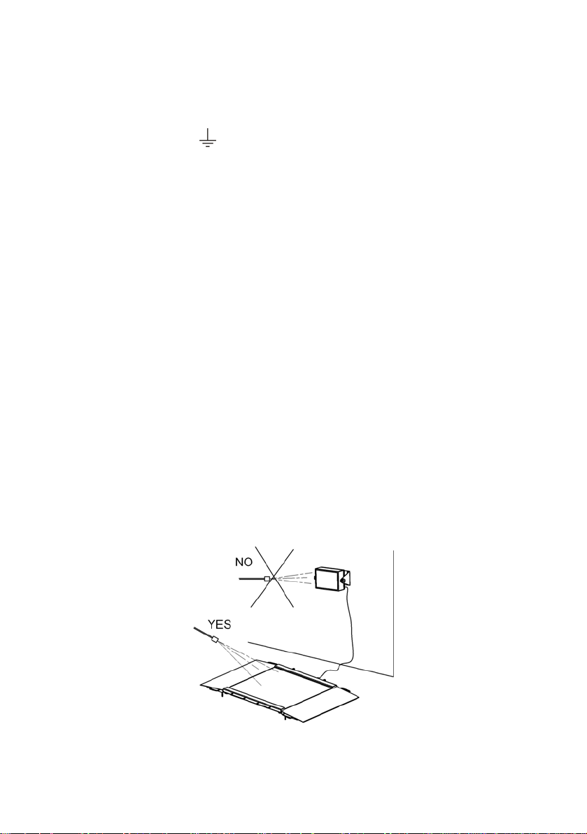
2.3. Operation in a strong electrostatic field
If the device is about to operate in a strong electrostatic field (e.g. printing
houses etc.) it should be connected to the earthing. Connect it to the
clamp terminal signed
.
2.4. Washing scales intended for meat processing industry
Weighing platforms are made of stainless steel (according to standards
PN–0H18N9, EN-1.4301, AISI–304) and silicon elements.
There is an exception, zinc coated overhead scales and painted livestock
scales made of mild constructional steel with aluminium cover plate on
the platform, polyester overlays and stainless steel or polyamide glands.
Caution:
Washing and disinfection agents should be matched to the scale.
Platforms of ramp and livestock scales as well as load-bearing structures
and weighing tracks of overhead scales can be washed with jet of water
(temp. up to +80°C) with an appropriate washing agent. Washing
measuring indicators/weighing terminals with the jet of hot water
is not allowed.
Caution:
It is advisable to cover measuring indicators/weighing terminals
while washing their surrounding with the jet of water.
- 9 -
Page 10
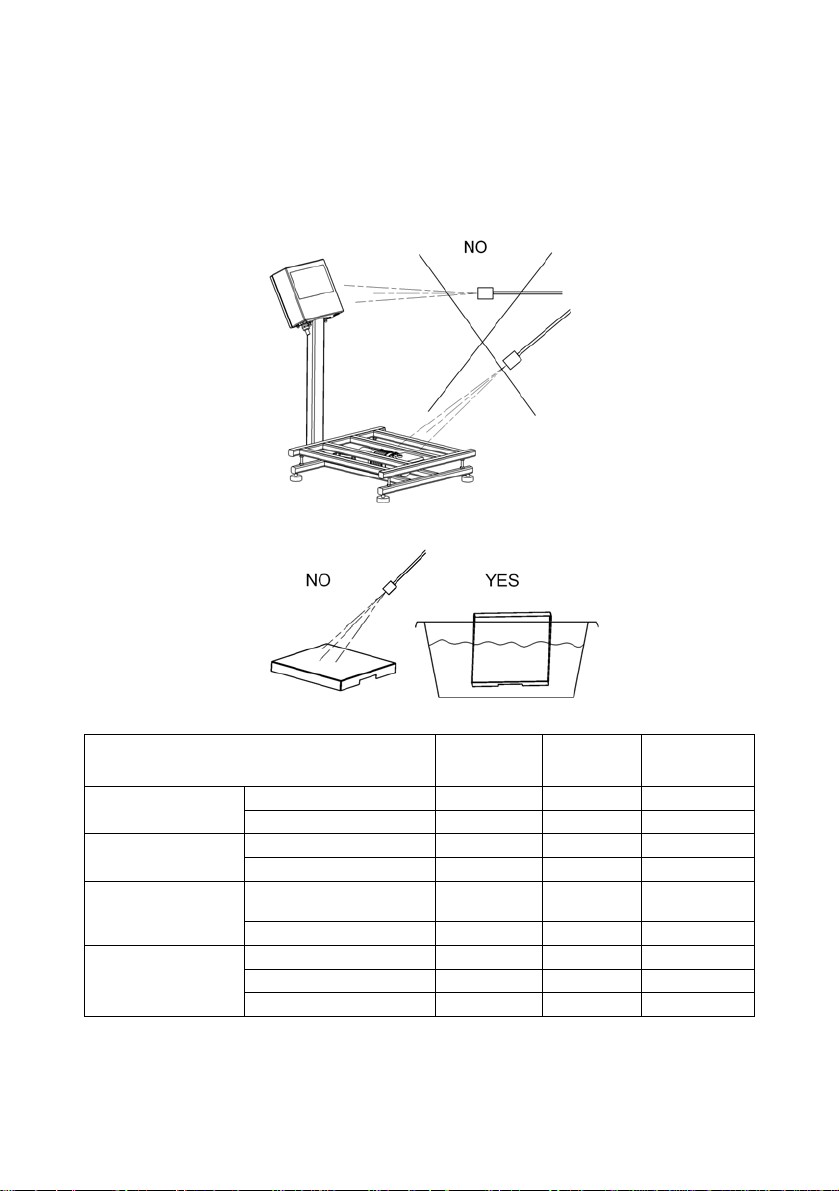
To wash waterproof platform scales and indicators/terminals neither jet
of water nor hot water shall be used, in order not to damage the silicon
gaiter that covers the load cell inside the platform and the overlay or
glands in the indicator/terminal. To wash pans of platform scales
they should be taken off first. Then they can be washed ether
with the jet of water or by immersion.
Ramp scales
Livestock scales
Overhead scales
Platform
waterproof scales
Type:
Platforms with tracks yes yes yes
Indicator/terminal yes no no
Platform with railing yes yes yes
Indicator/terminal yes no no
Load bearing structure
with he load cell
Indicator/terminal yes no no
Platform yes no no
Indicator/terminal yes no no
Taken off pan yes yes yes
Water with
detergent
yes yes yes
Jet of
water
Hot water –
max 80°C
- 10 -
Page 11

3. WARRANTY CONDITIONS
A. RADWAG is obliged to repair or change those elements that
appears to be faulty because of production and construction
reason,
B. Defining defects of unclear origin and outlining methods
of elimination can be settled only in participation of
a user and the manufacturer representatives,
C. RADWAG does not take any responsibility connected with
destructions or losses derives from non-authorized or inappropriate
(not adequate to manuals) production or service procedures,
D. Warranty does not cover:
• Mechanical failures caused by inappropriate maintenance of
the device or failures of thermal or chemical origin or caused
by atmospheric discharge, overvoltage in mains or other
random event,
• Inappropriate cleaning.
E. Loss of warranty appears after:
• Access by an unauthorized service,
• Intrusion into mechanical or electronic construction
of unauthorized people,
• Removing or destroying protection stickers.
F. The detailed warranty conditions one can find in warranty certificate.
G. Contact with the central authorized service:
+48 48 384 88 00 ext. 106 or 107.
- 11 -
Page 12
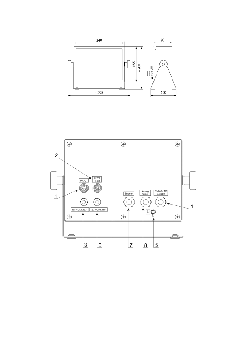
4. MAIN DIMENSIONS
Main dimensions of PUE C41H
5. DESCRIPTON OF CONNECTORS
Terminal connectors
1 – I/O connectors
2 – RS232, RS485 connector
3 – Tensometer gland
4 – Power supply gland
5 – Earthing terminal
6 – Additional platform gland (option)
7 –Ethernet gland (option)
8 – analogue output gland - voltage or current loop (option)
- 12 -
Page 13

Notice:
In accordance to the number of mounted modules the number and the
placement of glands and connectors can vary. Connectors and glands
mentioned in the standard solution appears in every option in the same
place regardless of the option.
6. UNPACKING AND MOUNTING
A. Take the device out of the package,
B. Put the scale on an even stiff ground,
C. Level the platform using an external or internal level condition
indicator. Use levelling feet to do it.
7. GETTING STARTED
• Switch off the scale using
• Wait for the test completion,
• Then you will see zero indication and following pictograms displayed:
- zero
- equilibrium
kg - weight unit
If the indication is not zero – press zero button.
– keep pressing it for about 0.5 sec,
- 13 -
Page 14
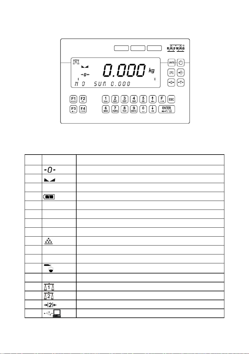
8. KEYBOARD
9. PICTOGRAMS
No Pictogram Description
1.
2.
3. kg (g)
4.
5. Net
6. Min
7. OK
8. Max Upper threshold or TOP mode
9.
10.
11.
12.
13.
14.
15.
16.
17.
% Weighings in percents
► Animals weighings
| ------ |
Zero indication (Autozero zone)
Equilibrium
Weighing mode
Battery/accumulator
Tare has been introduced
Lower threshold
Proper mass
Counting pieces
Dosing
Bargraph
First platform
Second platform
Second range of weightings’
Communication with a computer
- 14 -
Page 15
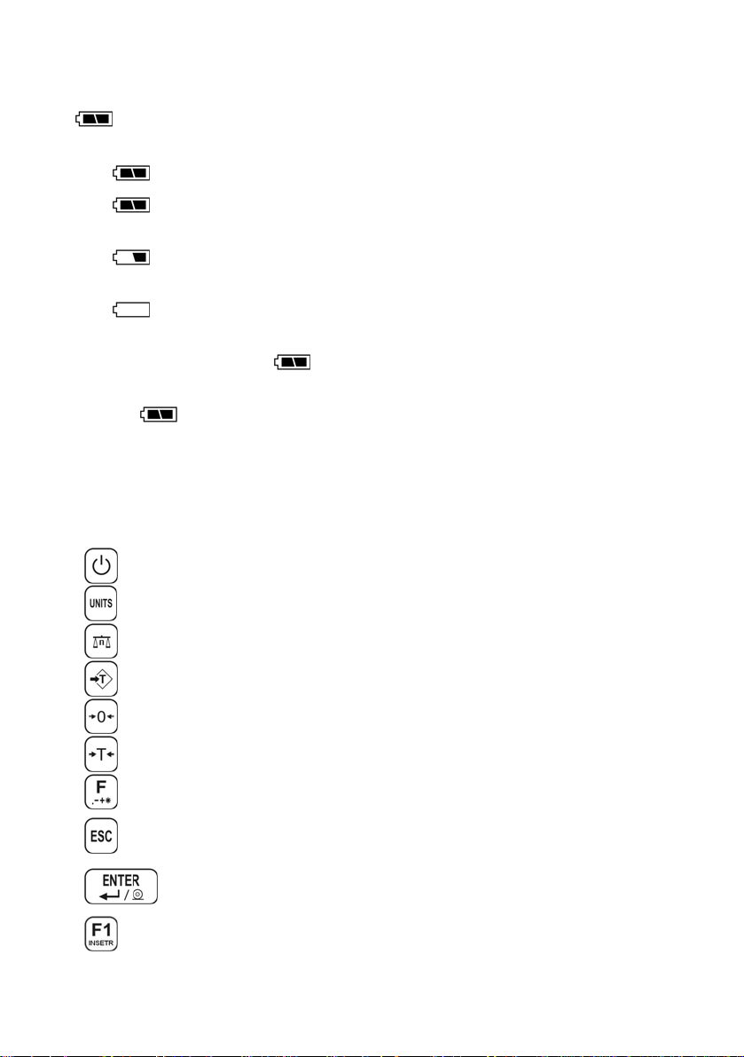
9.1. Battery charge indication
pictogram is situated in the upper right corner informed about the
discharge level or charging process:
• pictogram blinks: accumulator damaged or no accumulator,
• pictogram displayed continuously: it is charge between
70% and100%,
• pictogram displayed continuously: it is charge between
30% and70%,
• pictogram displayed continuously: it is discharge
(less than 30%), connect to the mains to charge,
• Internal elements of pictograms are displayed in sequence:
charging,
• No pictogram: power supply from mains, battery charges.
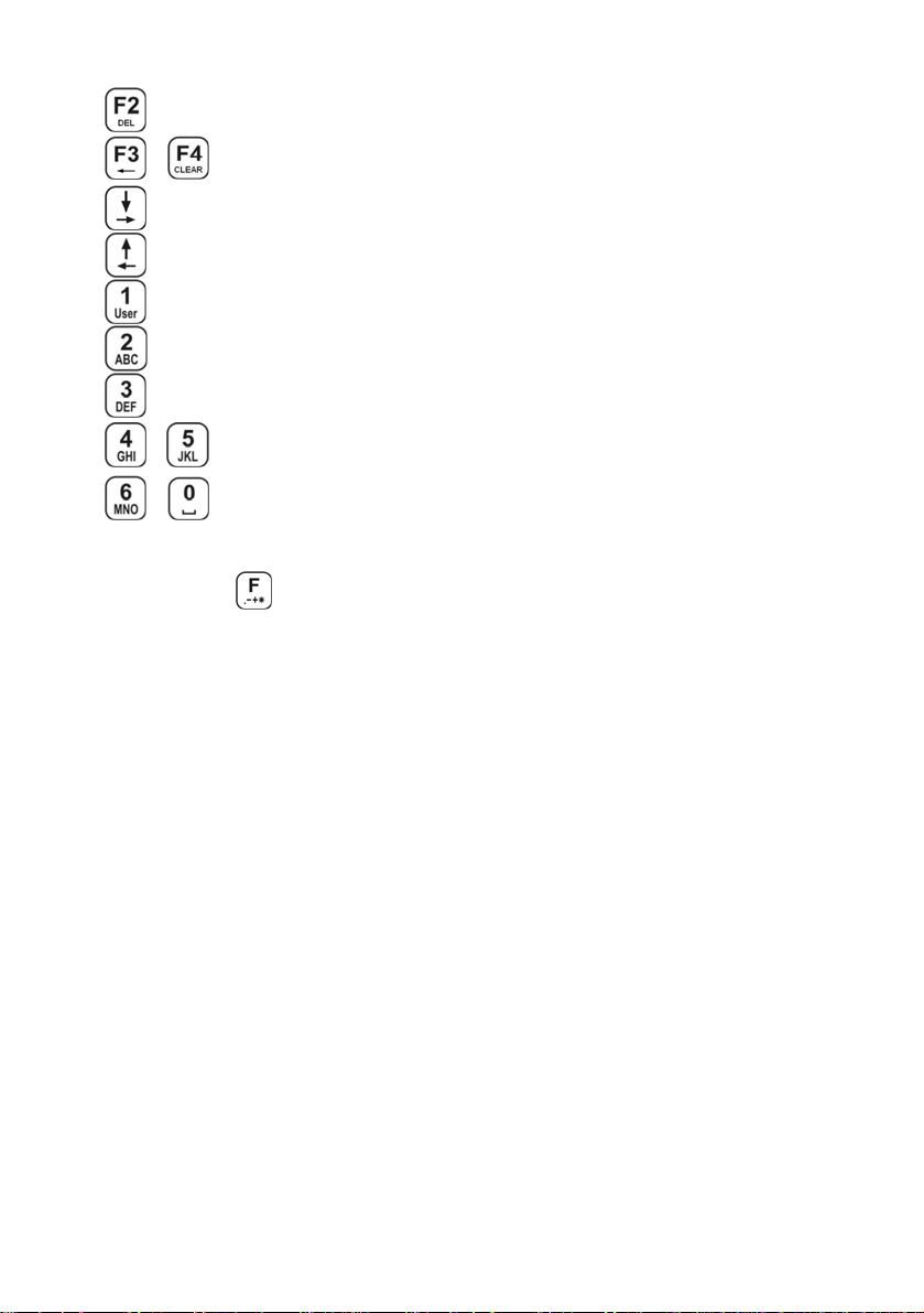
10. FUCTIONS OF KEYS
Keys Description
Turning on/off the scale
Toggling between weight units
Changing active platform
Inscribing tare value
Zeroing
Tarring
Function key (entering the menu)
Leaving a function without saving or reaching
a higher level of the menu
Printing out the result or confirming some entered data
Selection / viewing of articles from
the assortment database
- 15 -
Page 16
…
…
Selection purpose variables
N/A
Work mode selection
N/A
Log out
Inscribing MIN, MAX thresholds
View of statistics
N/A
…
Programmable keys
Caution:
After pressing
, functions of keys change while in the menu.
The way of using them is described farther.
11. MENU - PARAMETERS
11.1. Overview of parameters
The menu has been divided into 10 basic groups. Each group has its
individual name starting with the capital letter P. Names of groups
and their contents are shown below.
PARAMETERS
P 1 SCALE PARAMETERS
P 1.1 PLATFORM 1 PAR.
P 1.1.1 FITER | AVERAGE
P 1.1.2 MED. FILTER | YES
P 1.1.3 LO THRESH. | 20 d
P 1.1.4 TARE MODE | STDRD
P 1.1.5 START UNIT | kg
P 1.1.6 AUTOZERO | YES
P 1.1.7 DOS. FILTER | 1
P 1.2 PLATFORM 2 PAR.
- 16 -
Page 17

P 1.2.1 FITER | AVERAGE
P 1.2.2 MED. FILTER | YES
P 1.2.3 LO THRESH. | 20 d
P 1.2.4 TARE MODE | STDRD
P 1.2.5 BASIC UNIT | kg
P 1.2.6 AUTOZERO | YES
P 1.2.7 DOS. FILTER | 1
P 1.3 FACTORY NO | 0
P 2 COM PORTS PARAMETERS
P 2.1 RS 485
P 2.1.1 BAUD RATE | 9600
P 2.1.2 DATA BITS | 8
P 2.1.3 PARITY BIT | NO
P 2.1.4 STOP BITS | 1
P 2.2 RS 232 (1)
P 2.2.1 BAUD RATE | 9600
P 2.2.2 DATA BITS | 8
P 2.2.3 PARITY BIT | NO
P 2.2.4 STOP BITS | 1
P 2.3 RS 232 (2)
P 2.3.1 BAUD RATE | 9600
P 2.3.2 PARITY BIT | NO
P 2.4 ETHERNET
P 2.4.1 COMM MODE |
P 2.4.2 IP ADDRESS | 192.168.0.2
P 2.4.3 SUBNET MSK. | 255.255.255.0
P 2.4.4 GATEWAY | 192.168.0.1
P 2.4.5 LOCAL PORT | 4001
P 2.4.6 HOST IP | 192.168.0.3
P 2.4.7 HOST PORT | 2000
P 2.4.8 TIMEOUT | 60
P 3 DEVICES
P 3.1 COMPUTER
P 3.1.1 COMP. PORT | NO
P 3.1.2 ADDRESS | 1
P 3.1.3 COMP. PRINT | NONE
P 3.1.4 BASIC TRS. | YES
P 3.1.5 SYSTEM E2R | NO
P 3.1.5 E2R SYSTEM
P 3.1.5.1 ACTIVE SYS. | NO
P 3.1.5.1 WEIGH. BUFFER | 0
P 3.1.5.1 LOCK ASSOR. | NO
P 3.2.1 PRINT PORT | NO
P 3.3 BARCODE SCANNER
P 3.3.1 BARCOD. COM | NO
P 3.3.2 START
P 3.3.3 LENGTH | 0
P 3.4 TRANSP. CARD READER
P 3.4.1 READER COM | NO
SERVER
| 0
- 17 -
Page 18

P 3.5 ADDITIONAL DISPLAY
P 3.5.1 DISPL. PORT | NO
P 3.5.2 DISPL. TYPE | LCD
P 4 DATE / TIME
P 4.1 DISPL. TIME | * FUNCTION *
P 4.2 SET TIME | * FUNCTION *
P 4.3 DAT. FORMAT | YY-MM-DD
P 5 PRINTOUTS
P 5.1 AUTO. PRINT | WHEN STAB
P 5.2 STAB. PRINT | YES
P 5.3 CHECKWEIGHING | NO
P 5.4 PRINTOUT | STANDARD
P 5.5 PRINTOUT 1 |
P 5.6 PRINTOUT 2 |
P 5.7 PRINTOUT 3 |
P 5.8 PRINTOUT 4 |
P 6 DATABASES
P 6.1 LOGGING |
P 6.2 EDITION |
P 6.3 ANON. ACC. |
P 6.4 PASS. TYPE |
P 6.5 CODE TYPE |
P 6.6 STATISTICS |
P 7 WORK MODES
P 7.1 MODE ACCES.
P 7.1.1 WEIGHING |
P 7.1.2 TOP |
P 7.1.3 COUN. PCS |
P 7.1.4 CHECKWEIGH. |
P 7.1.5 ANIM. WEIGH. |
P 7.1.6 DOSAGE |
P 7.1.7 INTER. TERM. | YES
P 7.2 BUTTONS FUNCTIONS
P 7.2.1 B6 | NONE
P 7.2.3 B8 | NONE
P 7.2.4 B9 | NONE
P 7.2.5 B0 | NONE
P 7.3 ANIM. WEIGH.
P 7.3.1 WEIGH. TIME | 15
P 7.4 DOSAGE
P 7.4.1 DOSING NAM. | 1
P 7.4.2 DELAY | 5
P 7.4.3 CHUTE TIME | 5
P 7.4.4 OUTPUT MOD. | 1_2
P 7.4.5 TARRING | NO
P 7.4.6 DOSING CORRECTIONS
P 7.4.6.1 MODE | NONE
* FUNCTION *
* FUNCTION *
* FUNCTION *
* FUNCTION *
NO
ADMIN
ADMIN
NUM
NUM
GENERAL
YES
YES
YES
YES
YES
YES
P 7.2.2 B7 |
NONE
- 18 -
Page 19

P 7.4.6.2 START CORRECTIONS | 0.000
P 7.4.6.3 MAX CORRECTIONS | 0.000
P 7.4.6.4 AVERAGING VALUE | 3
P 8 I/O CONFIG
P 8.1 EXTERNAL BUTTONS
P 8.1.1 TARE BUTT. |
P 8.1.2 PRINT BUTT. |
P 8.1.3 ZERO BUTT. |
P 8.1.4 START BUTT. |
P 8.1.5 STOP BUTT. |
P 8.1.6 EXT. START |
P 8.1.7 TERM. BUTT. |
P 8.1.8 CHUTE PERM. |
P 8.2 OUTPUT CONF.
P 8.2.1 MIN |
P 8.2.2 OK |
P 8.2.3 MAX |
P 8.2.4 STABLE |
P 8.2.5 THRESH 1 |
P 8.2.6 THRESH 2 |
P 8.2.7 CHUTE |
P 9 OTHER
P 9.1 LANGUAGE |
P 9.2 DIODES
P 9.2.1 LED POWER |
P 9.2.2 RED DIODES |
P 9.2.3 GREEN DIOD. |
P 9.3 POWER SAVE |
P 9.4 BACKLIGHT
P 9.4.1 BL MAINS |
P 9.4.2 BL BATTER. |
P 9.5 BEEP |
P 9.6 KEYPAD TYPE | ABC2
P 9.7 SOFT. VER. | WTLS 1.7.5
P 10 USER CALIB.
P 10.1 PLATF. 1 CALIB
P 10.1.1 STRT M. ADJ. |
P 10.1.2 CALIBRATION |
P 10.2 PLATF. 2 CALIB
P 10.2.1 STRT M. ADJ |
P 10.2.2 CALIBRATION |
NO
NO
NO
NO
NO
NO
NO
NO
NO
NO
NO
NO
NO
NO
NO
ENGLISH
100%
NON-STAB.
STABLE
NO
YES
100%
YES
* FUNCTION *
* FUNCTION *
* FUNCTION *
* FUNCTION *
- 19 -
Page 20
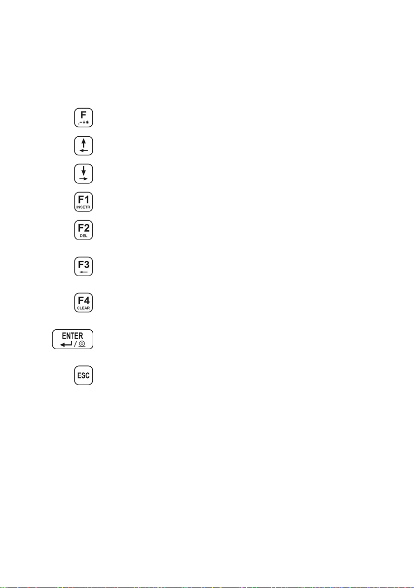
11.2. Navigating within the menu level
Use keyboard to browse the menu.
11.2.1. Keyboard
Entering the main menu, special characters in the editing field
Entering the search procedure of records in databases
Moving up (left)
Moving down (right)
Adding records in a database
Adding characters in an editing field
Clearing the editing field
Erasing a record in a database
Selecting and editing general purpose variables
START of dosing procedure
START of weighings animals
Deleting characters in editing field
Clearing editing field
Deleting database
Zeroing statistics
Entering submenus
Entering parameters
Confirming changes
Skipping changes
Leaving the menu level
- 20 -
Page 21
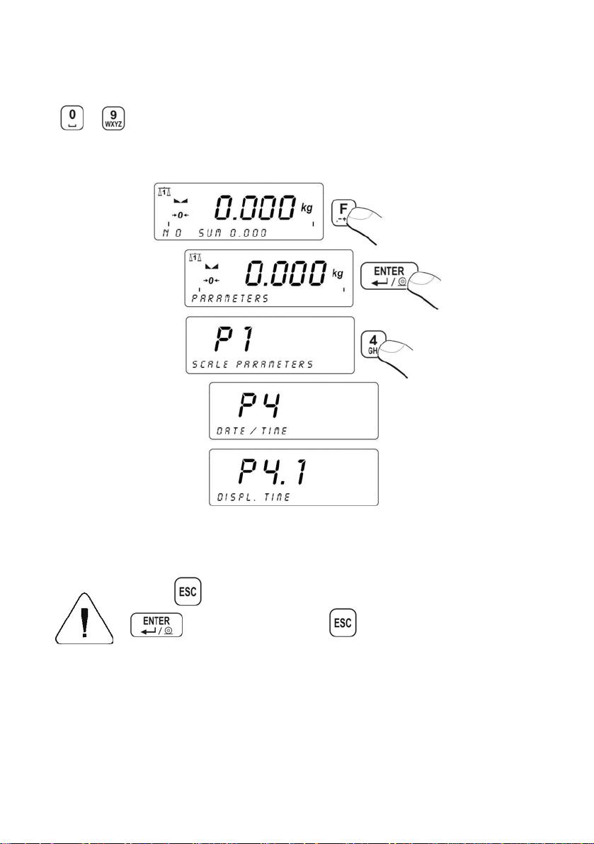
11.2.2. Quick access
It is possible to move quickly within the parameters’ menu using
to .
Procedure:
11.3. Return to weighing
Press
, until you see SAVE CHANGES ?. Then you press:
– confirms changes or – skips changes. Then the
scale returns to weighing.
- 21 -
Page 22
12. WEIGHING
Put a load you want to weigh on the weighing pan. When the
pictogram appears it means that the result is stable and ready to read.
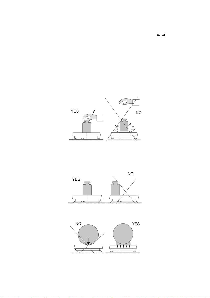
12.1. Operating conditions
In order to assure long-term operation and appropriate measurements of
weighted loads following precautions should be taken into consideration:
• Loads should be placed on the pan delicately and carefully
in order to avoid mechanical shocks:
• Loads should be placed centrally on the pan (errors caused
by eccentric weighing are outlined by standard PN-EN 45501
ch. 3.5 and 3.6.2):
• Do not load the pan with concentrated force:
- 22 -
Page 23
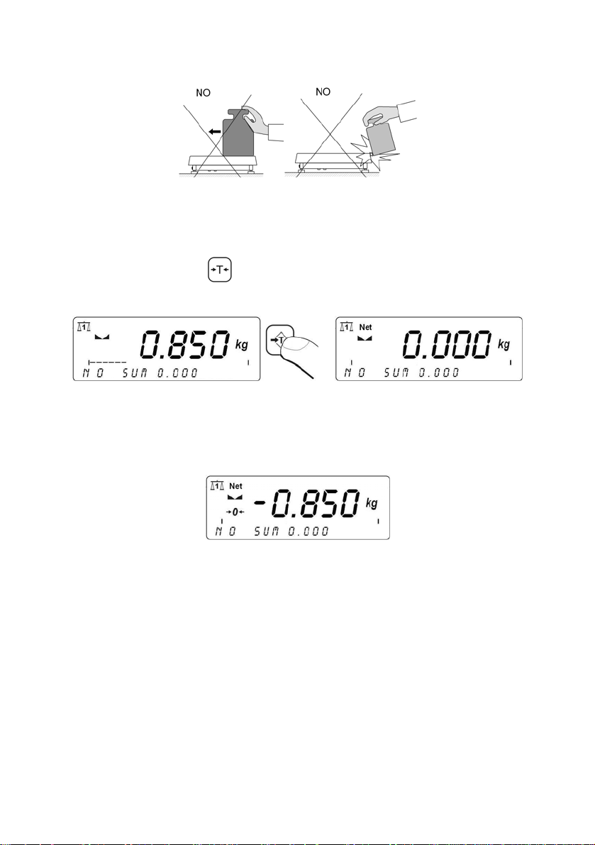
• Avoid side loads, particularly side shocks should be avoided:
12.2. Tarring
In order to determine the net mass put the packaging on the pan.
After stabilising press -
(Net pictogram will be displayed in the
left upper corner and zero will be indicated).
After placing a load on the weight pan net mass will be shown.
Tarring is possible within the whole range of the scale. After
unloading the pan the display shows the tarred value with
minus sign.
Caution:
Tarring cannot be performer when a negative or zero value
is being displayed. In such case Err3 appears on the display
and a short beep sound will be emitted.
12.3. Inscribing tare value
You can also inscribe a tare value:
Procedure:
While in weighings mode:
- 23 -
Page 24
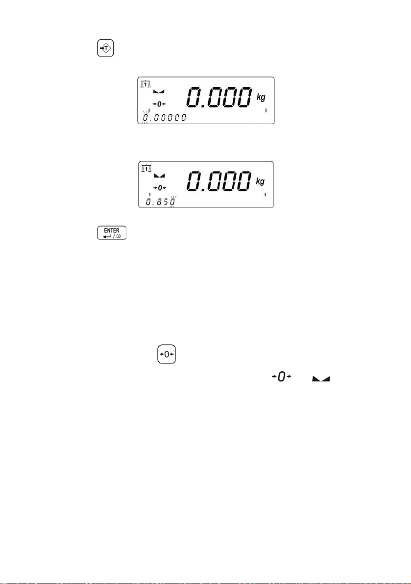
• Press ,
• In the lower line you will see an editing field:
• Inscribe the tare value:
• Press ,
• The scale return to weighings mode The inscribed tare value
can be seen on the display with „–” sign.
Tare can be inscribed anytime in weighings mode.
12.4. Zeroing
To ZERO the scale press: .
The scale will display zero and following pictograms:
and .
Zeroing is only possible within the scope of ±2% of full scale.
While zeroing outside the scope of ±2% you will see Err2.
Zeroing is possible only in stable state.
Caution:
Zeroing is possible only within ±2% of full range around zero. If the zeroed
value is beyond the interval of ±2%, Err2 is displayed and a short beep
sound will be emitted.
- 24 -
Page 25
12.5. Weighings in two ranges
Switching between the I range and the II range happens automatically
(exceeding Max of the I range).
Weighings in the second range is signalled by a pictogram in the top left
corner of the display.
Then weighings is done with the accuracy of the II range to the moment
of returning to zero (autozero range
) where the scale switches back
to the I range.
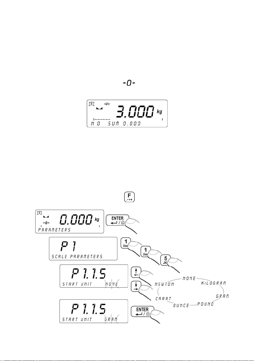
12.6. Toggling between weight units
12.6.1. Selection of basic unit
This function sets the unit that will be set after powering on.
Procedure:
• While In weighings mode press
and then:
- 25 -
Page 26
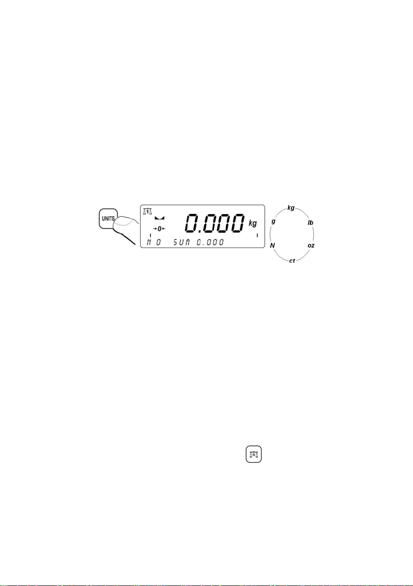
Selection:
• When the main unit is [kg], users can select among:
[kg, lb, oz, ct, N, g] , for verified scales [lb, oz, N]
are not accessible;
• When the main unit is [g], users can select among:
[g, kg, lb, oz, ct, N] , for verified scales [lb, oz, N]
are not accessible.
12.6.2. Toggling between weight units Press the Units key to toggle between weight units.
Accessible units:
• When [kg] is the basic unit, users can toggle between:
[kg, lb, oz, ct, N, g]. For verified scales [lb, oz, N]
are not accessible;
• When [g], is the basic unit, users can toggle between:
[g, kg, lb, oz, ct, N] For verified scales [lb, oz, N]
are not accessible.
Notice:
The terminal always starts working with the main (calibration) unit.
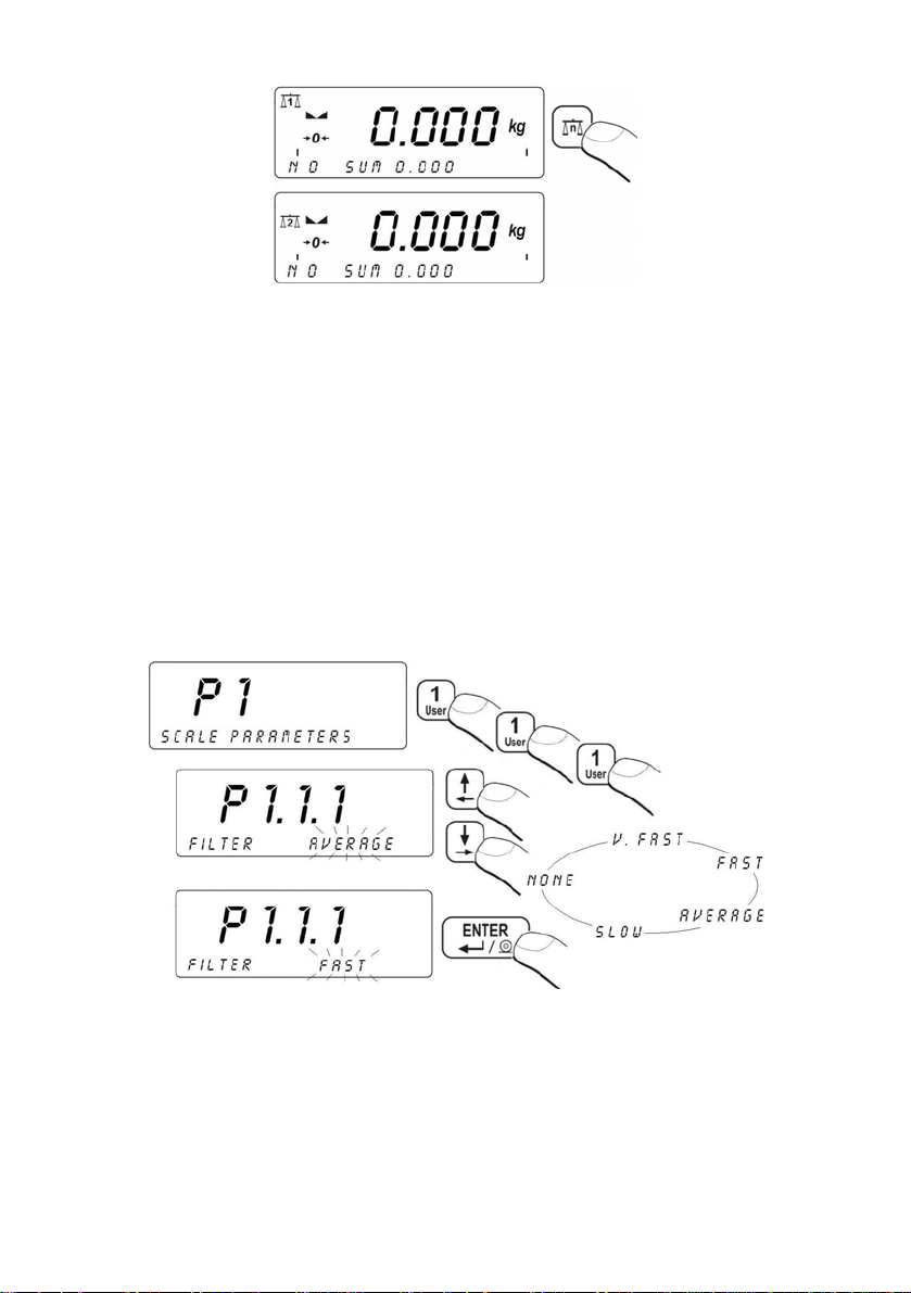
12.7. Switching between platforms
If a scale is equipped with two platforms press to change the
platform. The active platform is signalled by pictograms in the top
left corner of the display.
- 26 -
Page 27
13. MAIN PARAMETERS
Users can adjust the scale to external ambient conditions (filtering level)
or particular needs (autozero operation, tare memory). This parameters
are present in <P1 SCALE PARAMETERS>.
13.1. Filtering level Procedure:
• Enter <P1 SCALE PARAMETERS> and then:
Return to weighing:
See 11.3.
Notice:
The higher filtering level the longer stabilization time.
- 27 -
Page 28
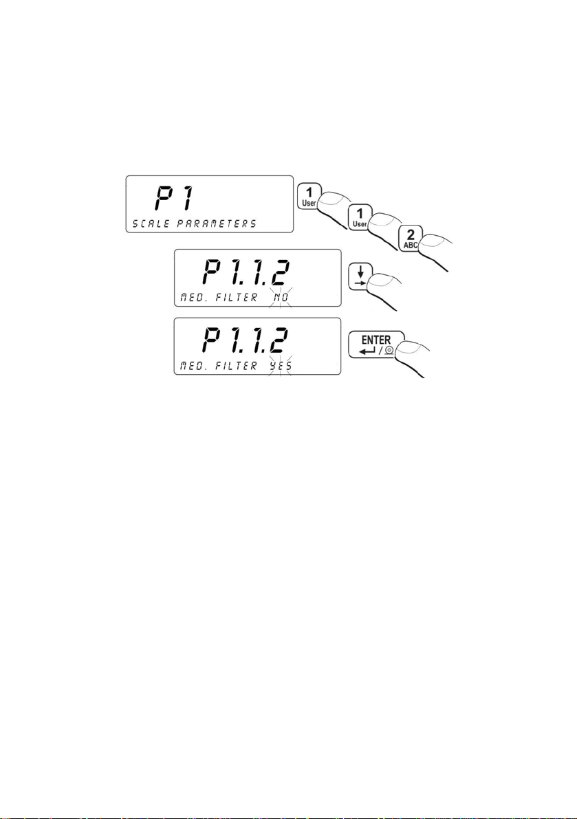
13.2. Median filter
This filter eliminates short mechanical shocks.
Procedure:
• Enter <P1 SCALE PARAMETERS> and then:
NO - filter disabled
YES - filter enabled
Return to weighing:
See 11.3.
13.3. Dosing filter setting
In PUE 41 terminals an special averaging filter for dosing process has
been implemented. The result of this filtration, instead of traditional filters
for static weighing, is compared with dosing setpoints. The filter parameter
is the number of samples from the A/D converter (1 to 10). When the filter
is set to 1 every reading from the A/D converter is compared with the
dosing setpoints, which does not introduce any delay. If the filter
parameter is set to n>1, the filtering result will be calculated as
an arithmetic average from the last n measurements.
n
=
XM
,where M is a filtering result from samples X1 to X
∑
i
=
1i
- 28 -
n .
Page 29

As dosing is a kind of dynamic state, which results in continuous changes
in measurements, the averaged number of samples in the filter have an
effect on the result. An example situation is illustrated below:
The upper blue line represents results for n=1 samples in the filter buffer
(averaging is off). The lower red line represents the same process when
the filter is set to n=10. The difference depends on the dynamics (dosing
rate) of changes either. The theory shows that the best filter parameter is
n=1 because the setpoints can be compared with the current dosed mass.
But in practice, there is a noise from different vibration sources registered
and sometimes external forces connected with kinetic and potential
energy of the poured material. It causes that the filter setting should
be matched experimentally.
Caution:
1. The subsequent readouts of the measured value from
the A/D converter is performed every 100 ms.
2. This filter operates only in dosing procedures.
- 29 -
Page 30
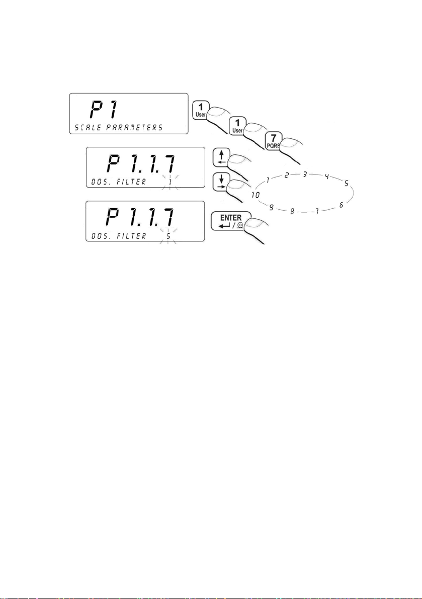
Procedure:
• Enter <P1 SCALE PARAMETERS > according
to 11.2. of the manual:
Return to weighing:
See 11.3.
13.4. Minimal mass parameter
Parameter PROG LO is related to following functions:
- automatic tare,
- automatic operation,
- weighing animals.
The next automatic tarring can be performed after the indication reaches
the gross value below LO THRESH.
For automatic weighing the next weighings can be performed after the
indication reaches the net value below LO THRESH.
The procedure of weighing animals will start after the gross animal mass
is greater than LO THRESH.
Procedure:
• Enter <P1 SCALE PARAMETERS> according to 11.2. and then:
- 30 -
Page 31

Return to weighing:
See 11.3.
13.5. Tare function
This parameter allows to set appropriate parameters for tarring.
Procedure:
• Enter <P1 SCALE PARAMETERS> according to 11.2. and then:
- 31 -
Page 32

AUTO
- disable automatic tare (the mode is remembered after
restart);
NORMAL
MEMORY
- tarring by pressing ;
- tare memory mode - the last tare value is being kept in
a non-volatile memory, Net pictogram is displayed.
SUM
- sum of tares – summing up a product tare value with
a tare from the database of tare values or with an
inscribed one.
Return to weighing:
See 11.3.
13.6. Autozero
The autozero function has been implemented in order to assure precise
indications. This function controls and corrects „0” indication. While the
function is active it compares the results continuously with constant
frequency. If two sequentional results differ less than the declared
value of autozero range, so the scale will be automatically zeroed
and the pictograms
and will be displayed.
When AUTOZERO is disabled zero is not corrected automatically.
However, in particular cases, this function can disrupt the measurement
process e.g. slow pouring of liquid or powder on the weighing pan.
In this case, it is advisable to disable the autozero function.
Procedure:
• Enter <P1 SCALE PARAMETERS> according to 11.2. and then:
- 32 -
Page 33

NO - Autozero disabled
YES - Autozero enabled
Return to weighing:
See 11.3.
14. PORTS PARAMETERS
It is possible to connect external devices (printer, computer) to the ports:
• RS 232 (1)
• RS 232 (2)
• RS 485
• Ethernet
Configuration can be done in: <P2 COM PORTS PARAMETERS>.
14.1. RS 232, RS 485 setting
For setting: RS 232, RS 485 use following parameters:
• Baud rate - 2400 - 115200 bit / s
• Data bits - 7, 8
• Stop bit - 1, 1.5, 2
• Parity - NONE, ODD, EVEN
Caution:
There is impossible to set data bits and stop bits for RS 232(2).
They are internally set to 8 bits and 1 stop bit.
14.1.1. Baud rate of RS 232 Procedure:
• Enter <P2 COM PORTS PARAMETERS> according
to 11.2. and then:
- 33 -
Page 34

Return to weighing:
See 11.3.
14.1.2. Baud rate of RS 485 Procedure:
• Enter < P2 COM PORTS PARAMETERS > according
to 11.2. and then:
Return to weighing:
See 11.3.
- 34 -
Page 35

14.1.3. RS 232 parameters Procedure:
• Enter <P2.2 RS232 (1)> and press ,
• Using
scroll to <P2.2.2 DATA BITS> and press :
• The selected value confirm with
• Using
go to <P2.2.3 PARITY BIT> and press :
• The selected value confirm with
• Using
go to <P2.2.4 STOP BITS> and press :
,
,
• The selected value confirm with
,
Return to weighing:
See 11.3.
Caution:
Search chapter 32.2.2 of this manual to find details on connecting
the scale with EDYTOR WPW via RS232.
- 35 -
Page 36

14.1.4. Setting of RS 485 parameters Procedure:
• Enter <P2.1 RS485> and press
,
• Using
go to <P2.1.2 DATA BITS> and press :
• The selected value confirm with
• Using
go to <P2.1.3 PARITY BITS> and press :
• The selected value confirm with
• Using
go to <P2.1.4 STOP BITS> and press :
,
,
• The selected value confirm with
Return to weighing:
See 11.3.
,
- 36 -
Page 37

14.2. ETHERNET setting ETHERNET can be configured in <P2.4 ETHERNET>.
Inventory of default parameters:
No NAME VALUE DESCRIPTION
Ethernet connection as Server or Client.
P2.4.1
WORK MODE SERVER, CLIENT
SERVER – scale waits for connection
CLIENT – scale initiates the connection
to a HOST.
P2.4.2
P2.4.3
P2.4.4
P2.4.5
P2.4.6
P2.4.7
P2.4.8
IP ADDRESS 192.168.0.2 Setting an IP address.
SUBNET MASK 255.255.255.0
GATEWAY 192.168.0.1
LOCAL PORT 4001
HOST IP 192.168.0.3
HOST PORT 2000
TIMEOUT 60
Setting a subnet mask for Ethernet
connection.
Setting a gateway for Ethernet
connection.
Setting a local port for Ethernet
connection. Only for devices that
work as SERVER. Servers waits
for connection on the specified port.
Setting a host IP address (IP of a device
to connect with). Applicable only for
devices configured as CLIENTs.
Setting a Host port (a port for connection
with a computer). Applicable only for
devices configured as CLIENTs.
Time (in seconds) after which noneactive Ethernet connection is being
broken. Set to 0 to stop breaking the
connection.
Caution:
1. For appropriate setting of: <P2.4.2 IP ADDRESS>,
<P2.4.3 SUBNET MSK>, <P2.4.4 GATEWAY> contact
the supervisor of the net to connect with;
2. The way of connection via ETHERNET to the program
EDYTOR WPW is described in chapter 32.2.3.
3. The scale does not allow the automatic fetch of net
configuration from DHCP servers.
- 37 -
Page 38

Return to weighing:
See 11.3.
15. EXTERNAL DEVICES
15.1. Cooperation with a computer
WPW scales can cooperate with computers of IBM PC class.
In submenu <P3.1 COMPUTER> you can configure interfaces.
WPW scales can cooperate with the EDYTOR WPW program. The
indicator window reflects the view of a typical indicator display with all
necessary pictograms. The program allows to configure a scale easily,
design printout patterns, supervise databases, set parameters, collect
and save printouts etc.
Caution:
1. Installation version of EDYTOR WPW is accessible on the Internet:
www.radwag.com. Look up: Products / Measuring indicators / PUE
C41H.
2. Check chapter 32.2 for details on cooperation with EDYTOR WPW.
15.1.1. Select the communication port scale-computer
The computer can be connected to:
• RS 232 (1)
• RS 232 (2)
• RS 485
• Ethernet
Procedure:
• Enter <P3 DEVICES> according to 11.2. and then:
- 38 -
Page 39

Caution:
Standard scales can communicate with computers only via RS232(1)
or RS485.
Return to weighing:
See 11.3.
15.1.2. Type of printout scale – computer Procedure:
• Enter <P3 DEVICES> according to 11.2. and then:
- 39 -
Page 40

Caution:
The procedure of designing non-standard printouts is described
in chapter 17.6 of this manual.
Return to weighing:
See 11.3.
15.1.3. Address setting Procedure:
• Enter < P3.1 COMPUTER > according to 11.2. and then:
• Inscribe a value (0 to 254) and press
.
Return to weighing:
See 11.3.
15.1.4. Order operating of communication protocol
User in parameter <P3.1.4 BASIC TRS.> has possibility to set
communication protocol designed to communicate between
RADWAG scale and external device.
- 40 -
Page 41

Procedure:
• Enter < P3.1 COMPUTER > according to 11.2. and then:
Return to weighing:
See 11.3.
15.1.5. Cooperation with „E2R System”
Scales can cooperate with computer software „E2R System” that is
a modular system for complex production supervising by monitoring
of weighings processes.
Caution:
Enabling cooperation of the device with program „E2R System” can
be done only by the manufacturer or authorized Service.
15.1.5.1. Enabling „E2R System” In order to allow the cooperation with „E2R System” enable parameter
<P3.1.5.1 ACTIVE SYS.>.
Procedure:
• Enter < P3.1 COMPUTER > according to 11.2. and then:
- 41 -
Page 42

Return to weighing:
See 11.3.
15.1.5.2. Buffer for weighings
Users can declare the quantity of performed measurements to be saved
in the internal buffer in the scale in case of operating OFF-LINE (no
transmission to „E2R SYSTEM”). After reconnecting with „E2R SYSTEM”
all measurements from the internal buffer will be sent to the database
of the computer program.
Procedure:
• Enter < P3.1 COMPUTER > according to 11.2. and then:
• Type on the scale keyboard the required buffer length and confirm
by pressing button
.
Caution:
The buffer equal to 0 results in saving all weighings in the database
in case of operating OFF-LINE.
- 42 -
Page 43

Return to weighing:
See 11.3.
15.1.5.3. The lock of product change
Users can lock changing products by scale operators cooperating with
„E2R SYSTEM”.
Procedure:
• Enter < P3.1 COMPUTER > according to 11.2. and then:
Return to weighing:
See 11.3.
15.2. Cooperation with printers
Press to send the current measurement together with the
weighing unit to a printer.
15.2.1. Communication port scale - printer
Following ports can be used:
• RS 232 (1),
• RS 232 (2),
• RS 485,
• Ethernet.
- 43 -
Page 44

Procedure:
• Enter <P3.2 PRINTER> and then:
Return to weighing:
See 11.3.
15.3. Cooperation with a barcode scanner
The scale gives possibility to cooperate with barcode scanners.
It is used for quick search of database of assortment.
Caution:
In <P2 COM PORTS PARAMETERS> set the baud rate for the same
as your barcode scanner requires (default 9600b/s). See details for
cooperation with barcode scanners in chapter 32.1 of this manual.
15.3.1. Select a communication port for the scanner Procedure:
• Enter <P3.3 BARCODE SCANNER> and then select
a communication port with the barcode scanner:
- 44 -
Page 45

Return to weighing:
See 11.3.
15.3.2. Setting the START parameter Procedure:
• Enter <P3.3 BARCODE SCANNER> and then set the START
parameter – a character number in barcodes that is to be
analysed during the assortment database search:
- 45 -
Page 46

Return to weighing:
See 11.3.
15.3.3. Setting the LENGTH parameter Procedure:
• Enter <P3.3 BARCODE SCANNER> and then set the LENGTH
parameter – the number if character in barcodes (counting from
START) that is to be analysed during the assortment database
search:
Return to weighing:
See 11.3.
15.4. Cooperation with a transponder card reader
Operators can be logged in after powering up the device or previous
logging out by:
• Inscribing a password using the scale keyboard,
• Using transponder cards to log in.
- 46 -
Page 47

Caution:
In parameters <P2 COM PORTS PARAMETERS> set the baud rate
for the one that requires the barcode scanner (default 9600b/s).
15.4.1. Selecting of communication port
In parameters <P3.4 TRANSP. CARD READER.> and then
select a communication port with the transponder card reader:
Return to weighing
See 11.3.
15.4.2. Procedure of ascribing card numbers to operators
In order to log in using a transponder card you need to have it previously
ascribed to a specific operator.
Procedure:
• Connect a transponder card reader to RS232/RS485 on the back
wall of the terminal,
• Select a communication port (see 15.4.1),
- 47 -
Page 48

• In parameters <P2 COM PORTS PARAMETERS> set the baud
rate (default 9600b/s).
• Enter the database of operators and then find and edit the
required operator. Find <CARD CODE> field:
• Approaching a card to the reader results in displaying the card
number in the <CARD CODE> field,
• Press
to confirm,
• Return to weighing – chapter 11.3.
15.5. Cooperation with an additional display
15.5.1. Selecting a communication port
Additional displays can be connected to:
• RS 232 (1)
• RS 232 (2)
• RS 485
Procedure:
• Enter < P3.5 ADDITIONAL DISPLAY > according to 11.2. and then:
- 48 -
Page 49

Return to weighing:
See 11.3.
15.5.2. Selecting an additional display type Procedure:
• Enter < P3.5 ADDITIONAL DISPLAY > according to 11.2. and then:
Return to weighing:
See 11.3.
- 49 -
Page 50

16. DATE / TIME SETTING
Enter <P4 DATE / TIME> to set these parameters.
16.1. Time view Procedure:
Return to weighing:
See 11.3.
16.2. Time setting Procedure
• Enter the DATE / TIME> and then:
- 50 -
Page 51

• After pressing you will see:
• Enter an appropriate value and confirm it with ,
• You will have to enter the following variables in sequence:
- MONTH
- DAY
- HOUR
- MINUTE
• After confirming the last value with you will see the current
date and time:
Return to weighing:
See 11.3.
16.3. Date format
Date can be displayed in different format.
Procedure:
• Enter <P4 DATA / TIME> and proceed as follows:
- 51 -
Page 52

YY - MM - DD
YY - DD - MM
DD - MM - YY
- year - month – day
- year - day - month
- day - month - year
Return to weighing:
See 11.3.
17. PRINTOUTS
17.1. Printout type Setting the <P5.1 AUTO. PRINT> parameter can set a type of printout: Procedure:
• Enter <P5 PRINTOUTS> according to 11.2. and then:
- 52 -
Page 53

NO
WHEN STB
CONTIN.
LAST STB
- manual printout
- automatic printout after stabilising
- continuous printouts
- printing the last stable result after taking
of a load, before reaching the LO-. value
ONE PRINT
EACH STABILE
-
Single print over -LO-
- Automatic printout of each stable measurement
over the -LO-
Return to weighing:
See 11.3.
17.2. Printout of stable / unstable data Enter <P5.2 STAB. PRINT>, to set the printout as:
• Stable data,
• Immediate data.
- 53 -
Page 54

Procedure:
• Enter <P5 PRINTOUTS> according to 11.2. and then:
Return to weighing:
See 11.3.
Notice:
In case of verified scales <P5.2 STAB. PRINT> is not accessible for users.
17.3. Checkweighing mode
In this mode printout is possible only when the result is between
Min, Max thresholds.
Procedure:
• Enter <P5 PRINTOUTS> according to 11.2. and then:
- 54 -
Page 55

Return to weighing:
See 11.3.
17.4. Non-standard printouts
Users have possibility to design non-standard printouts
in <P5.4 PRINTOUT>.
Procedure:
• Enter <P5 PRINTOUTS> according to 11.2. and then:
Return to weighing:
See 11.3.
17.5. Designing non-standard printouts
To create a non-standard printout:
• Enter <P5 PRINTOUTS> according to 11.2. and then:
- 55 -
Page 56

• After pressing , you will see a cursor. Software is ready
to accept your data.
Non-standard printout can comprise:
• Constant texts,
• Variables from different work modes (mass, date, thresholds etc.),
• Non-standard printout design can include max. 320 characters,
• Non-standard printout sent to a printer can include max. 640
characters,
• Up to 4 non-standard printouts can be designed.
Caution:
1. During designing non-standard printouts all special characters
like CRLF, tabulators etc. have to be added.
2. Examples of designing non-standard printouts can be found
in chapter 32.4.
17.6. Texts in non-standard printouts
17.6.1. Code format
% XXX - sending to a printer a variable XXX value
XXX YY - sending to a printer YY (declared) characters
of XXX variable value justified to the left.
Caution:
Every non-standard printout should be terminated with \0 character
- 56 -
Page 57

17.6.2. Variables appearing in all modes
CODE DESCRIPTION
%000 Mass in a basic unit of the active platform
%001 Mass in a current unit of the active platform
%002 Date
%003 Time
%004 Date and time
%005 Calibration unit
%006 Current unit
%007 Min threshold (for checkweighing)
%008 Max threshold (for checkweighing)
%009 Min threshold (for checkweighing) 7 digits
%010 Max threshold (for checkweighing) 7 digits
%011 Net mass in the calibration unit
%012 Gross mass in the calibration unit
%013 Display result in a present unit
%014 Tare in calibration unit
%015 Statistics – ordinal number
%016 Statistics – sum in the calibration unit
%017 Statistics – average value in the calibration unit
%018 Statistics – minimal value in the calibration unit
%019 Statistics – maximal value in the calibration unit
%020 Statistics – unit
%021 Single pcs mass
%022 Standard (nominal) mass in Checkweighing
%023 Platform number
%024 Operator name
%025 Operator code
%038 Article name (assortment)
%039 Article code (assortment)
%040 Article EAN code (assortment)
%042 Minimal mass of article (assortment)
%043 Maximal mass of article (assortment)
%044 Article tare value (assortment)
%056 Net mass (lb)
%058 Number of digits after the point (calibration unit)
%059 Number of digits after the point (current unit)
%060 Net mass in EAN 13 (6-character code)
%061 Net mass in EAN 13 (7-character code)
%064 Net mass in EAN 128
- 57 -
Page 58

%067 Net mass (lb) in EAN 128
%068 Gross mass EAN 128
%070 Date in EAN 128
%126 Reference quantity for counting pieces
%127
%128 Batch number (6 characters)
%131 Dosing net mass in calibration unit
%132 Present number of records in the weighing database
%134 Batch number (10 characters)
%136 Present correction for dosing in calibration unit
%137 Present corrected MAX threshold for dosing
%138 Loss in weight in per cents
%139 Net mass in calibration unit decreased by loss in weight
%140 Net mass in present unit decreased by loss in weight
Difference of tare values
(a product tare value subtracted from present tare value)
17.6.3. Variables for printing out weighings from the database
%073 Weighing net mass
%075 Weight unit
%076 Weighing date
%077 Weighing time
%078 Operator code
%079 Assortment code
%080 Contractor code
%083 Number of series
%084 Platform number
%135 Batch number
This program includes a standard pattern of printouts from the
database (pattern name:
WG01 ), with following variables:
- Net mass of weighing,
- Date,
- Time.
Caution:
Remember that the name of a new printout design should have the
following pattern:
WGXX , where: XX – subsequent number of printout.
- 58 -
Page 59

17.6.4. Variables for printouts of reports from weighings
%086 Weighing status (threshold for weighing - MIN, OK or MAX)
%087 Sum of weighings
%088 Weight unit
%089 Number of weighings
%090 Start date
%091 End date
%092 Operator code
%093 Assortment code
%096 Batch number printout
%097 Series number
%098 Type of weighings (%, pcs, kg etc.)
%099 Platform number
%129* Present record name for generating a complex report
%130*
Marking of the space for weighings in a complex report (the variable needs to
be situated at the beginning and in the end of the requested printing space)
*) – Variables for complex report pattern (i.e. with heading and footer).
An example of complex report is described in ch.32.5 of this manual.
The program includes 4 patterns of reports from weighings.
is the English equivalent of
equivalent of
Caution:
RP03 :
Name Comprised variables
RP01 Sum of weighings
RP03 Operator code
RP01 and RP04 is an English
Number of weighings
Start date
End date
Assortment code
Contractor code
Sum of weighings
Number of weighings
Start date
End date
RP02
1. Remember that the name of a new printout design should have the
following pattern:
RPXX , where: XX – subsequent number of
printout.
- 59 -
Page 60

2. Standard software do not include a database of contractors. That is
why the printout
RP03 substitutes „Contractor code” with dashes
< - - - - >.
17.6.5. Special characters that can be used in non-standard printouts
\\ Single character - „\”
\c CRLF
\r CR
\n LF
\t Tabulator
\0 End of printout
Every text in a non-standard printout may include up to 320 characters
(letters, digits, special characters, spaces).
Example:
„ R A D W A G ”
D a t e :
T i m e :
M a s s :
S i g n a t u r e : . . . . . . . . .
The inscribed data for:
“ R A D W A G ” \ C \ T D A T E : % 0 0 2 \ C \ T T I M E : % 0 0 3 \ C \ T
M A S S : % 0 0 0 \ C \ C \ T \ T S I G N A T U R E : . . . . . . . . . . \ C \ 0
18. DATABASES
18.1. Logging in
In case of activating of logging procedure (submenu <P6.1 LOG IN>),
an operator after switching on has to perform a jogging procedure which
consists in inscribing a password.
Operators can also use a transponder cards for this procedure provided
the terminal is equipped in a transponder card reader (see 15.4).
- 60 -
Page 61

Procedure:
• Enter <P6 DATABASES> according to 11.2. and then:
Return to weighing:
See 11.3.
Users can log in even if this procedure is disabled at the start:
• Turn on the device ,
• Press
during a display test,
• Program will show the following window:
Notice:
In case there are no data in the operators’ database press
to skip
the logging procedure and add at least one operator with the highest
level access. If no ADMINISTRATORS are defined there will be no
access to some functions designated only for administrators.
- 61 -
Page 62

18.2. Access level
18.2.1. Access level to edition of databases
Any administrator is able to set one of three levels of edition
of databases: administrator, advanced operator or operator.
Procedure:
• Enter <P6 DATABASES> according to 11.2. and then:
Return to weighing:
See 11.3.
Notice:
This setting is valid although the standard logging is disabled.
18.2.2. Access level for disabled logging
The scale program gives possibility to set an access level in case
of disabling logging procedure.
Procedure:
• Enter <P6 DATABASES> according to 11.2. and then:
- 62 -
Page 63

OPERATOR -
Can perform weighings, edit P1, P4, P9
parameters; cannot edit databases and erase
statistics; cannot change weighing thresholds
Min, Max, cannot adjust the standard mass
in modes “counting pieces” and “deviations”.
ADVANCED OP. -
Can perform weighings and edit parameters
except P8, P10 and P6.1, P6.2, P6.3; can
edit databases except operators;
ADMIN -
Have a full access to parameters and
databases, can perform user calibration
(in non-verified scales).
Return to weighing:
See 11.3.
18.3. Password type
It is possible to set the password type to inscribe.
Procedure:
• Enter <P6 DATABASE> according to 11.2. and then:
- 63 -
Page 64

NUM
ALPHANUM
-
only digits 0 to 9
- alphanumeric password
Return to weighing:
See 11.3.
18.4. Type of codes
There is possible to select a type of codes. You can set this in database
settings.
Procedure:
• Enter <P6 DATABASES> according to 11.2. and then:
- 64 -
Page 65

NUM
ALPHANUM
-
only digits 0 to 9
- alphanumeric password
Return to weighing:
See 11.3.
18.5. Access to edition of databases Procedure:
Return to weighing:
See 11.3.
Caution:
Users can access different things in the menu according to their
Access levels. It also concerns an access to databases.
18.6. Quick searching in databases
Users can search databases using different criteria:
• Code,
• Name,
• Record number.
This procedure is applicable for operators and assortment.
- 65 -
Page 66

18.6.1. Quick code search Procedure:
• While in any work mode press
(select / view products
in the assortment database) and then:
• Inscribe the product code you search and then press
.
• The program displays the product you search in the bottom line.
Caution:
If the search result is not successful the <NO RECORD> message
in the bottom line is displayed for 1 second and then software
returns to displaying the current record.
Return to weighing:
See 11.3.
18.6.2. Quick name search Procedure:
• While in any work mode press
in the assortment database) and then:
(select / view products
- 66 -
Page 67

• Inscribe the product name you search and then press
• The program displays the record you search in the bottom line.
Caution:
You can inscribe a part of the product name to start searching.
The program will display the first string it encounters with the same
beginning as the inscribed one. If the search result is not successful
the <NO RECORD> message in the bottom line is displayed for 1
second and then software returns to displaying the current record.
18.6.3. Quick number search Procedure:
• While in any work mode press
(select / view products in the assortment database),
• Scale program displays the record number one in the bottom line:
.
• Using numeric keys
to enter a required record number,
• Scale program displays the record in the bottom line:
- 67 -
Page 68

Return to weighing:
See 11.3.
18.7. User database
The database of operators can hold up to 100 records in standard setting
of databases.
Procedure:
• Enter databases according to 18.5. and then:
• When the database is empty you will see:
• Press
• In the bottom line you will see the first line for inscribing data.
• You can enter the edition end confirm any data by pressing
You can select fields using
to add an operator,
.
- 68 -
.
Page 69

Fields in an operator record:
NAME
Operator name (max. 40 characters)
CODE
PASSWORD
CARD CODE
AUTHORIS.
• After defining all fields in a record of operator press ,
Operator code (max. 6 characters)
Password for logging (max. 8 characters)
Transponder card code (max. 15 digits)
Access level
• Then you will see:
• Press
if you want to save,
• You will see an operator name and a position in the database:
• To delete an operator press
• To edit a defined operator press
• To delete all records press
Return to weighing:
See 11.3.
,
,
.
- 69 -
Page 70

18.8. Assortment database
The assortment database can comprise up to 3000 records.
Procedure:
• Enter databases according to 18.5 of this manual:
• In case the database is empty you will see:
• Press to add a record,
• You will see the first empty record in editing mode.
• Entering edition and confirming changes can be made by pressing
. Select fields to be changed using keys.
- 70 -
Page 71

Fields in the assortment database:
NAME
CODE
EAN
MIN
MAX
TARE
STR
CORRECTION
DOSE.
OUTPUT NO.
FAST DOSE.
OUTPUT NO.
Product name (max. 40 characters)
Product code (max. 7 characters)
Constant code that can be used as a barcode (max. 15 digits)
Minimal mass for checkweighing
Maximal mass for checkweighing
Tare value (it is preset automatically after selecting a product)
The mass value that is added to or substracted from the nominal
mass in dosing
Declaration of output number for precise dosing of a product
Declaration of output number for fast dosing of a product
• After defining all fields press
,
• You will see the following inscription:
• Press to save changes,
• You will see the products name you have edited:
• To erase the selected record press ,
• To edit the selected record press
• To clear the database press
,
.
Return to weighing:
See 11.3.
- 71 -
Page 72

18.9. Weighings database
Every result sent from the scale to a printer is also saved in the database
of weighings. There is possible to save up to 30 000 records in database
in standard setting.
Procedure:
• Enter the database according to 18.5 and then:
• When the database is empty you will see:
• In case when the database is not empty, you will see the first
record (date, mass, unit):
• To delete the selected record press ,
- 72 -
Page 73

• To delete all records press .
• To print the selected record press
Notice:
.
1. Single record can be deleted only when first in the database
(the oldest record).
2. The printout pattern and variables for designing non-standard
printouts are described in ch. 17.6 of his manual.
Return to weighing:
See 11.3.
18.10. Database of tare values
It is possible to hold up to 100 tare values (for every platform).
Procedure:
• Press twice in any work mode,
• In case when there is no record you will see the following window:
• To enter a tare value
• Using numerical keys
with
• Press
,
one more time to return to the weighing mode.
,
to inscribe a value and confirm
You will see the entered value with „–”.
• To delete a selected tare press
• To edit a selected tare press
• To delete all tare press
,
,
,
- 73 -
Page 74

• You can browse the database using or by inscribing
a position number using
to .
Caution:
If users confirm a tare value greater than the maximal value (full scale)
you will see the following inscription: <TOO HIGH VALUE>.
Return to weighing:
See 11.3.
18.11. General purpose variables
You can inscribe any text to be memorized for printouts.
You can view or edit them from the level of databases in the menu
or using a quick access method by pressing
mode (apart from dosing)
.
from any work
18.11.1. Editing general purpose variables Procedure:
• Enter databases according to 18.5 and then:
- 74 -
Page 75

• To add or modify a record (inscribing characters like in mobile
phones) press
• To add or modify a record (inscribing only digits 0 to 9) press
• To clear a field press
,
,
when you are in,
• Using appropriate keys inscribe a variable and confirm
it by pressing
• You can browse the variables using
a variable position number
,
or by inscribing
to to get a quick access.
Return to weighing:
See 11.3.
18.11.2. General purpose variables in printouts
The database of general purpose variables can comprise up to 100
records. Each record can hold up to 320 characters. Each variable
has prescribed a code number formatted as% XXX or
% XXX -
inserting to the printer buffer a dedicated variable, where:
XXX YY:
XXX – is between 801 to 900, which is equivalent to
subsequent records in the database (e.g. code 802 is
equivalent to the 2nd position in the database).
XXX YY - inserting to the printer buffer a dedicated variable, where YY
is a declared quantity of characters from a variable XXX.
Example:
„RADWAG”
Date:
Time:
Mass:
signature:.........
- 75 -
Page 76

Where: < „RADWAG”> is a universal variable No 3. After entering nonstandard printouts (see 17.5) we design a printout:
% 8 0 3 \ C \ T D A T E : % 0 0 2 \ C \ T T I M E : % 0 0 3 \ C \ T M
A S S : % 0 0 0 \ C \ C \ T \ T S I G N A T U R E: . . . . . . . . . \ C \ 0
19. REPORTS FROM WEIGHINGS
Users can print reports from weighings.
Reports can be filtered according to:
- start date,
- end date,
- operator code,
- assortment code,
- type of weighing,
- weighing platform number,
- number of series,
- batch number.
19.1. Editing reports
While in any work mode press
Return to weighing:
See 11.3.
and then:
- 76 -
Page 77

19.2. Printouts of reports
After entering (see ch. 19.1) you will see the following display:
• To edit variables press ,
• Confirm changes by pressing
• To filter according to the selected variable press
,
,
and you will see the following window:
• Press to go to the next variable,
Caution:
Code filter of assortment or operator can have folowing values:
• ALL (key
) – complex report comprising weighings for each
product or operator separately,
• NON-ZERO (key
) - complex report comprising weighings
for each product or operator separately.
An example of complex report pattern is described in ch. 32.5 of this
manual.
- 77 -
Page 78

• After editing all variables go to the next item <PRINT REPORT>
by pressing
• Press
.
, you will see the window:
• Using
• Press
select one of four patterns (details in ch.17.6),
to print out the report.
Return to weighing:
See 11.3.
Caution:
If a user disables filtering according all the variables, the program
will print out a report from all the weighings.
20. CONFIGURATION OF EXTERNAL INPUTS / OUTPUTS
20.1. Configuration of external buttons
Following external buttons can be connected:
TARE BUTT
PRINT BUTT
ZERO BUTT
START BUTT
STOP BUTT
EXT. START
TERM. BUTT.
CHUTE PERM.
Tare button
Print button
Zero button
Start button,
Start weighing animals button
Button for breaking dosing process,
Button for breaking weighing animals
Input signal allowing to START dosing
Terminating of dosing process
Perdition input signal for chute
- 78 -
Page 79

Procedure:
• To declare a number of input ascribed to the button enter
<P8.1 EXTERNAL BUTTONS> and then,
• Press
• Press
, you will see <P8.1.1 TARE B.>,
:
• Confirm your selection with
• Using
go to the next parameter.
,
Caution:
You can ascribe all your buttons accordingly. Remember that the
standard solution has only 3 inputs.
Return to weighing:
See 11.3.
20.2. Configuration of outputs
Users can configure outputs according to their needs.
You can declare outputs:
MIN
OK
MAX
STABLE
THRESH 1
Mass below the Min threshold
Mass between Min and Max threshold
Mass over the Max threshold
Stable result over the LO threshold
Threshold of passing from dosing to precise
dosing in dosing mode
THRESH 2
CHUTE
Completing dosing process
Chute control
- 79 -
Page 80

Procedure:
• To declare an output number connected with the function,
enter <P8.2 OUTPUT CONF.> and then:
• Press
• Press
, you will see <P8.2.1 MIN>,
:
• Confirm the selected value with ,
• Using
go to the next function.
Notice:
You can ascribe all functions to outputs accordingly. Remember
that the standard solution has only 3 reed relay outputs.
Return to weighing:
See 11.3.
21. STATISTICS
21.1. Updating statistics
All statistics are updated in real time after every subsequent measurement
after putting a load on the pan, reaching equilibrium, and pressing
Number of weighings and sum are show in the lower line of the display.
.
Statistics can be calculated globally (does not depend on the selected
product) or separately for every product from the assortment database.
It can be set in parameters <P6.6 STATISTICS>.
- 80 -
Page 81

Procedure:
• Enter < P6 DATABASES > according to 11.2. and then:
GENERAL
ASSORT
- global statistics,
- statistics for every product.
Return to weighing:
See 11.3.
21.2. Printouts of statistics
Users can print out statistics in any work mode.
Procedure:
- 81 -
Page 82

Using users can view the current statistics: SUM – total mass of
all details, AVG – every mass of all details, MIN – minimal mass, MAX maximal mass.
Printout example:
number of weighing
N = 7
S U M = 3 . 8 0 0 k g
A V G = 0 . 5 4 3 k g
M I N = 0 . 2 0 0 k g
M A X = 1 . 0 0 0 kg
total mass
average mass of all loads
minimal mass
maximal mass
-
21.3. Zeroing statistics
Users can delete statistics to start a new series of measurements.
Procedure:
Return to weighing:
See 11.3.
- 82 -
Page 83

Caution:
1. When a user changes a work mode all statistics are automatically
deleted.
2. Statistic data are common from all platforms connected
(no separate calculations).
22. OTHER PARAMETERS
Users can set parameters that influence the weighings procedure. There
are included in <P9 OTHER> e.g. language, backlight, BEEP sound.
22.1. Language setting Procedure:
• Enter <P9 OTHER> according to 11.2. and then:
Return to weighing:
See 11.3.
- 83 -
Page 84

22.2. LED power setting
According to the requirements (e.g. intensity of external light) it is possible
to change the light flux from LEDs in the scale of 0% to 100%.
Procedure:
• Enter <P9.2 DIODES> according to 11.2. and then:
Return to weighing:
See 11.3.
22.3. Work modes for LEDs In <P9.2 DIODES> users can chose a work mode for LEDs. Procedure:
• Enter <P9.2 DIODES> according to 11.2. and then:
- 84 -
Page 85

RED LEDS NONSTAB.
RED LEDS STABLE
RED LEDS OFF
GREEN LEDS NONSTAB.
GREEN LEDS STABLE
GREEN LEDS OFF
Return to weighing:
See 11.3
diodes start to lit after exceeding
the LO threshold (see 13.3),
diodes start to lit after exceeding
the LO and reaching equilibrium,
diodes not work,
diodes start to lit after exceeding the LO,
diodes start to lit after exceeding the LO
and reaching equilibrium,
diodes not work.
- 85 -
Page 86

22.4. Automatic power down Changes can be made in <P9.3 POWER SAVE>. When the
POWER SAVE function is enabled the device switches off
after 5 min. Provided no changes on the pan appeared
(no changes on the display).
Function setting
POWER SAVE = NO Disabled Disabled
POWER SAVE = YES Enabled Enabled
POWER SAVE = AUTO * Disabled Enabled
Operation
Mains Accumulator
* power save mode for the internal power supply.
Procedure:
• Enter <P9 OTHER> according to 11.2. and then:
Return to weighing:
See 11.3.
- 86 -
Page 87

22.5. Backlight
According to the requirements (e.g. intensity of external light)
it is possible to:
• Switch on/off or set the backlight operation to AUTO – when supplied
from mains,
• Change the backlight intensity in the scale of 0% to 100% - when
supplied from an accumulator (lower backlight intensity increases
the operation time when supplied from the accumulator).
22.5.1. Backlight – power supply from mains Procedure:
• Enter <P9 OTHER> according to 11.2. and then:
NO
YES
AUTO
Return to weighing:
See 11.3.
- backlight switched off
- backlight switched on
- backlight switched off automatically
- 87 -
Page 88

22.5.2. Backlight - power supply from the accumulator Procedure:
• Enter <P9 OTHER> according to 11.2. and then:
Return to weighing:
See 11.3.
Notice:
Backlight operation shortens time between subsequent recharges
of the accumulator.
22.6. “Beep” sound – key-press reaction Procedure:
• Enter the <P9 OTHER> according to 11.2. and then:
- 88 -
Page 89

NO - no “beep” after pressing keys
YES - “beep” after pressing keys
Return to weighing:
See 11.3.
22.7. Keypad modes
The program allows to chose between alphanumeric keypad modes for
inscribing texts.
Procedure:
• Enter <P9 OTHERS> according to 11.2. and then:
- 89 -
Page 90

2ABC ABC2 -
Digits come first after pressing a key
Letters come first after pressing a key
Return to weighing:
See 11.3.
22.8. Software version view Users <P9.7 SOFT. VER.> can view a software version number. Procedure:
• Enter <P9 OTHER> according to 11.2. and then:
Return to weighing:
See 11.3.
23. SCALE CALIBRATION
An option only for non-verified scale
Scales require to recalculate internal divisions to more suitable ones (e.g.
g, kg etc.). In order to do this they require a calibration factor. It is adjusted
during the calibration procedure using a mass standard. Calibration should
be made when weighing a standard mass shows a different mass value.
- 90 -
Page 91

23.1. Calibration procedure
• Enter <P10 USER CALIB.> according to 11.2. and then:
• Unload the pan,
• Press
ADJ. START MASS, in the bottom line,
. During adjusting a start mass you will see:
• After completing this procedure you will see the following window:
• Place the required mass on the platform 1 then press
,
• During the calibration process you will see: ADJ. CALIB. FACTOR,
in the bottom line.,
• After the procedure is completed you will see in: UNLOAD THE PAN
in the bottom line,
• After taking off the calibration weight :
• Return to weighing, saving parameters.
Return to weighing:
See 11.3.
- 91 -
Page 92

23.2. Start mass adjustment
It is possible to adjust only a start mass, it helps to correct the start zero
when the span does not change.
Procedure:
• Enter <P10 USER CALIB.> according to 11.2. and then:
• Unload the scale,
• Press
ADJ. START MASS, in the bottom line,
. During adjusting a start mass you will see:
• After completing this procedure the scale will return to the
following window:
• Return to weighing, saving parameters.
Return to weighing:
See 11.3.
- 92 -
Page 93

24. WORK MODES
24.1. Accessibility of work modes
In <P7.1 ACCESSIBILITY> users can declare work modes that are
accessible after pressing
.
Procedure:
• Enter <P7 WORK MODES> according to 11.2. and then:
NO - mode denied
YES - mode accessible
Return to weighing:
See 11.3.
Caution:
This way you can disable/enable all accessible work modes.
- 93 -
Page 94

24.2. Programmable keys
In parameter group <P7.2 KEY FUNCTIONS> users can ascribe different
functions to keys:
, , , or to get an easiest access to
different functionalities.
Procedure:
• Enter <P7 WORK MODES> and then:
• Using and select a key to ascribe ( , , , or ).
• Enter the parameter pressing
• Using
and select the required function and press .
,
Return to weighing:
See 11.3.
The inventory of functions accessible for ascribing to keys:
Name Description
DIGIT. SERIES NO
ALPHA. SERIES NO
PRINTOUT 1
PRINTOUT 2
PRINTOUT 3
PRINTOUT 4
EDIT. PRINTOUT 1
EDIT. PRINTOUT 2
Inscribing 6-digit batch number
Inscribing 6-character batch number
Printing non-standard printout No 1
Printing non-standard printout No 2
Printing non-standard printout No 3
Printing non-standard printout No 4
Edit non-standard printout No 1
Edit non-standard printout No 2
- 94 -
Page 95

EDIT. PRINTOUT 3
EDIT. PRINTOUT 4
ASSORTMENT CODE
EAN ASSORT. CODE
STAT. PRINTOUT
STAT. PRN. DELETE
STAT. DELETE
TIME VIEW
WEIGH. REPORT
WEIGH. DATABASE
VAR. 1 ALPHA
VAR. 2 ALPHA
VAR. 3 ALPHA
VAR. . 4 ALPHA
VAR. 5 ALPHA
VAR. 1 DIGIT.
VAR. 2 DIGIT.
VAR. 3 DIGIT.
VAR. 4 DIGIT.
VAR. 5 DIGIT.
KEYPAD MODE
LO THRESHOLD
STRT M. ADJ.
CALIBRATION
AVER. TIME
N1 *
M1 *
N2 *
M2 *
C LABELS NO *
Edit non-standard printout No 3
Edit non-standard printout No 4
Quick search of the assortment database using
a product code
Quick search of the assortment database using
a product EAN code
Printing statistics
Printing statistics with deleting counters
Deleting statistics from the last measurement series
Time and date view
Edit a report from weighings
Direct access to the database of weighings
Inscribing universal variable No 1 (40 characters)
Inscribing universal variable No 2 (40 characters)
Inscribing universal variable No 3 (40 characters)
Inscribing universal variable No 4 (40 characters)
Inscribing universal variable No 5 (40 characters)
Inscribing universal variable No 1 (40 digits)
Inscribing universal variable No 2 (40 digits)
Inscribing universal variable No 3 (40 digits)
Inscribing universal variable No 4 (40 digits)
Inscribing universal variable No 5 (40 digits)
Selecting a keypad mode
Setting minimal mass as a condition of operation
some functions
Start mass adjustment procedure (user calibration)
Span adjustment procedure (user calibration)
Averaging time for weighing animals
Setting counter N1 (number of weighings which triggers
off automatic printing of c label)
Setting mass M1 (mass of weighings which triggers
off automatic printing of c label)
Setting counter N2 (number of weighings which triggers
off automatic printing of cc label)
Setting mass M2 (mass of weighings which triggers
off automatic printing of cc label)
Setting the number of C labels to be printed
- 95 -
Page 96

CC LABELS NO *
MULTIPLIER *
RECIPE CODE *
RECIPE REPORT *
CONTRACTOR CODE *
MATERIAL CODE *
PRINT C *
PRINT CC *
NEW ASSORT.
NEW CONTRACT. *
NEW MATERIAL. *
NEW RECIPE. *
DIGIT. BATCH NO
ALPHA. BATCH NO
LOSS OF MASS
Setting the number of CC labels to be printed
Setting the recipe multiplier
Inscribing a recipe code for a quick search of recipes
Access to the database of reports from recipes
(e.g. for printing them)
Inscribing a contractor code for a quick search of contractors
Inscribing a material code for a quick search of materials
Printing a C label
Printing a CC label
Adding a new product to the assortment database
Adding a new contractor to the database of contractors
Adding a new material to the database of materials
Adding a new recipe to the database of recipes
Inscribing 10-digit batch number
Inscribing 10-character batch number
Loss of mass in per cents
* - This function is not attached to the STANDARD software.
24.3. +/- control according to an inscribed standard mass While in weighing mode users can define (MIN, MAX).
Procedure:
• Using to numerical keys inscribe a MIN threshold
and confirm with
,
- 96 -
Page 97

• You will see the following display:
• Using to numerical keys inscribe a MAX threshold
and confirm with
,
• Software returns to WEIGHING.
While setting these thresholds following features are important:
• Symbols: Min, OK, Max in the upper line of the display:
• Designation of the proper interval (OK) on the bargraph:
• Three fields of signalling LEDs over the display:
Left – red – when this field shines the mass is lower than
the Min threshold;
Middle – green – Designation of the proper interval OK
between MIN and MAX thresholds;
Right – red – when this field shines the mass is higher
than the Max threshold.
- 97 -
Page 98

Notice:
Users can use this function in other work modes like counting pieces,
weighing in percents etc. Only values and units can change.
24.4. Maximal force latch Procedure:
• Enter the TOP work mode:
• TOP selection is signalled by the Max pictogram in the upper
line of the display:
• When a force acting on the pan changes on the display only
the maximal value can be seen,
• Remove the acting force,
• Press before the next measurement.
Return to weighing:
See 11.3.
24.5. Counting pieces
The standard software is equipped in a counting pieces procedure.
If counting pieces is to be proceeded in a package/container, tare
the package/container first.
- 98 -
Page 99

24.5.1. Enabling work modes
• COUNTING PCS procedure is active when
pictogram
is displayed.
24.5.2. Setting standard mass by inscribing the mass of a single piece
Procedure:
• Enter COUNTING PCS and then:
Press
to initialise COUNTING PCS. with automatic setting
of standard mass.
Notice:
The mass of a single piece cannot be lower than 0.1d and greater than
the full scale.
- 99 -
Page 100

24.5.3. Setting the standard mass by declaring the quantity of a sample
Procedure:
• Enter COUNTING PCS. and then:
While inscribing a sample quantity it should be remembered that the
mass of a single piece should not be lower than 0.1 d and the total
mass of a sample (all pcs) should not be lower than 1 d. An error
appears when this two conditions are not performed.
• After inscribing a required sample quantity press and you
will see:
If pieces are to be weight in a container put the container first and tare it.
Then put a load of pieces, wait for the equilibrium (
pressing
.
) confirm it by
Software automatically calculates a single piece mass and goes to
Counting pieces:
- 100 -
 Loading...