

RADWAG WLY12/KTPS/D2, WLY3/KTPS/D2, WLY6/KTPS/D2, WLY6/KTPS/C1/R, WLY12/KTPS/C1/R User Manual
...
User Manual
Scales of Y/KTPS series
Manual number:
ITKU-51-03-01-11-A
Control of Packaged Goods
Network version
• WLY/KTPS Scales
• WPY/KTPS Scales
MANUFACTURER OF ELECTRONIC
WEIGHING INSTRUMENTS
RADWAG Wagi Elektroniczne, 26–600 Radom Bracka 28 Street - POLAND
Phone +48 48 38 48 800, phone/fax. +48 48 385 00 10
Selling department +48 48 366 80 06
www.radwag.com

2
JANUARY 2011

3
Table OF CONTENTS
1. INTENDED USE..........................................................................................................................5
2. PRECAUTIONARY MEASURES................................................................................................5
3. WARRANTY CONDITIONS........................................................................................................6
4. UN ACKING AND MOUNTING.................................................................................................6 P
4.1.
PY/KTPS/C1 scales...........................................................................................................6 W
4.2.
WPY/KTPS/D2 scales...........................................................................................................7
5. SCALE CONSTRUCTION ..........................................................................................................8
5.1. Main dimensions....................................................................................................................8
5.1.1. Y/KTPS/C1 scales ................................................................................................8 WP
WPY/KTPS/D2 scales................................................................................................8 5.1.2.
5.2.
Description of connectors......................................................................................................9
5.2.1. ...............................................................................9 Connectors’ description in PUE 7
5.2.2.
.............................................................................9 Connectors’ description in PUE 7P
5.2.3.
..................................................................................10 Description of glands PUE 7P
5.2.4.
Connector with RS232 and I/O.................................................................................10
6. GETTING STARTED ................................................................................................................11
7. KEYPAD OVERLAY.................................................................................................................11
8. FUNCTIONS OF KEYS.............................................................................................................12
8.1. eys on the overlay.............................................................................................................12 K
8.2.
Screen function buttons.......................................................................................................12
9. INDICATING WINDOW.............................................................................................................13
10. PROGRAM STRUCTURE ......................................................................................................14
10.1. Inventory of parameters....................................................................................................15
10.1.1. Scale parameters - weighing..................................................................................15
10.1.2. Communication ...................................................................................................... 15
10.1.3. Devices ..................................................................................................................16
10.1.4. Display ...................................................................................................................17
10.1.5. Others ....................................................................................................................17
10.1.6. User Calibration .....................................................................................................18
10.2. Navigating within the menu...............................................................................................18
10.2.1. Buttons...................................................................................................................18
10.2.2. Return to weighing .................................................................................................19
11. WEIGHING..............................................................................................................................20
11.1. erational use ...........................................................................................20 Conditions of op
11.2.
ng..............................................................................................................................21 Zeroi
11.3.
ng...............................................................................................................................21 Tarri
11.4.
Weighing for dual range scales.........................................................................................22
12. SCALE PARAMETERS..........................................................................................................22
12.1. .......................................................................................................................23 Median filter
12.2.
ilter..................................................................................................................................23 F
12.3.
............................................................................................................................24 Autozero
12.4.
Minimum weight for different functions (LO) .....................................................................24
13. COMMUNICATION .................................................................................................................25
13.1. .................................................................................................................25 RS 232 settings
13.2.
T setting...........................................................................................................25 ETHERNE
13.3.
TCP protocol setting .........................................................................................................26
14. DEVICES.................................................................................................................................26
14.1. Computer ..........................................................................................................................26
14.1.1. Computer port ........................................................................................................27

4
14.1.2. Computer address..................................................................................................27
14.2. Printe ................................................................................................................................27 r
14.2.1.
Printer port .............................................................................................................28
14.2.2. Printer code page...................................................................................................28
14.3. Barcode scanner...............................................................................................................28
14.3.1. Port for barcode scanner........................................................................................29
14.3.2. Offset......................................................................................................................29
14.3.3. Code length............................................................................................................29
14.4. Transponder card reader ..................................................................................................30
14.4.1. Com port for transponder card readers..................................................................30
15. DISPLAY.................................................................................................................................31
15.1. ys....................................................................................................................31 Function ke
15.2.
Displaying platforms..........................................................................................................32
16. OTHER PARAMETERS..........................................................................................................33
16.1. ........................................................................................................................33 Languages
16.2.
time........................................................................................................33 Setting date and
16.3.
.....................................................................................................................34 Sound signal
16.4.
.....................................................................................................34 Touch panel calibration
16.5.
...............................................................................................................35 Software version
16.6.
Factory number.................................................................................................................35
17. CUSTOMER CALIBRATION..................................................................................................35
17.1. dure........................................................................................................35 Calibration proce
17.2.
Start mass adjustment......................................................................................................37
18. COOPERATION WITH PROGRAM KTP NET .......................................................................38
18.1. ith computers...............................................................................................38 Connection w
18.2.
Choosing product..............................................................................................................39
18.2.1. Choosing products by entering identifier................................................................40
18.2.2. Product name related searching ............................................................................40
18.2.3. Product code related searching .............................................................................41
18.3. Choosing operators...........................................................................................................41
18.3.1. Choosing operators by entering identifier ..............................................................42
18.3.2. Wybór z listy po nazwie operatora .........................................................................42
18.3.3. Wybór z listy po kodzie operatora..........................................................................42
18.3.4. Choosing operators using RFID readers................................................................43
18.4. uantity .....................................................................................................43 Entering batch q
18.5.
number...................................................................................................43 Entering a batch
18.6.
...........................................................................................................44 Starting test control
18.7.
control with average tare...........................................................................................44 Test
18.8.
y – full control ...........................................................................................................45 Empt
18.9.
Full – empty control...........................................................................................................46
18.10. Estimating average tare..................................................................................................47
19. TECHNICAL PARAMETERS .................................................................................................49
19.1. /KTPS series .............................................................................................49 Scales of WLY
19.2.
Scales of WPY/KTPS series.............................................................................................50
20. ERROR MESSAGES..............................................................................................................51
21. APPENDIX F - Communication with barcode scanners .................................................... 52

5
1. INTENDED USE
Scales of WPY/KTPS series together with KTP NET software constitute
a multi-stand system (network). Each scale is an independent scale and
information about the status of testing are sent in real time. The computer
program allows to collect data in real time from every connected scale.
The system allows to start test controls from scales or the computer level.
Cooperation scale-computer:
• Inventory of subsequent weighings in the database,
• Automatic printout of reports directly after a control has been completed,
• Sending identity codes from a scale to the computers to identify goods
and operators (product code, operator code, batch quantity, batch
number, Start/Stop test control),
• Defining product codes with description s (names) on the computer level.
Users can add individual names that are specific for the working place.
2. PRECAUTIONARY MEASURES
A. Please, read carefully this user manual before and use the device
according to its intended use;
B. Weighed loads should be placed in possibly central part of scale pan;
C. Do not clean the device with agents causing corrosio n;
D. Weighing pan should be loaded with goods having gross mass lower
than maximal capacity of the scale;
E. Do not leave loads on the pan for longer period of time ;
F. In case of failure, immediately disconnect scale power supply;
G. Devices that are to be withdrawn from usage should be utilized
according to the law.

6
3. WARRANTY CONDITIONS
A. RADWAG is obliged to repair or change those elements that appears
to be faulty because of production and construction reason,
B. Defining defects of unclear origin and outlining methods of elimination
can be settled only in participation of a user and the manufacturer
representatives,
C. RADWAG does not take any responsibility connected with destructions
or losses derives from non-authorized or inappropriate (not adequate
to manuals) production or service procedures,
D. Warranty does not cover:
• Mechanical failures caused by inappropriate maintenance of
the device or failures of thermal or chemical origin or caused
by atmospheric discharge, overvoltage in mains or other
random event,
• Inappropriate cleaning.
E. Loss of warranty appears after:
• Access by an unauthorized service,
• Intrusion into mechanical or electronic construction
of unauthorized people,
• Installing another operating system,
• Removing or destroying protection stickers.
F. The detailed warranty conditions one can find in warranty certificate.
G. Contact with the central authorized service:
+48 48 384 88 00 ext. 106 or 107.
4. UNPACKING AND MOUNTING
4.1. WPY/KTPS/C1 scales
A. Take the device out of the package,
B. Put the scale on an even stiff ground,
C. Remove transport protection:
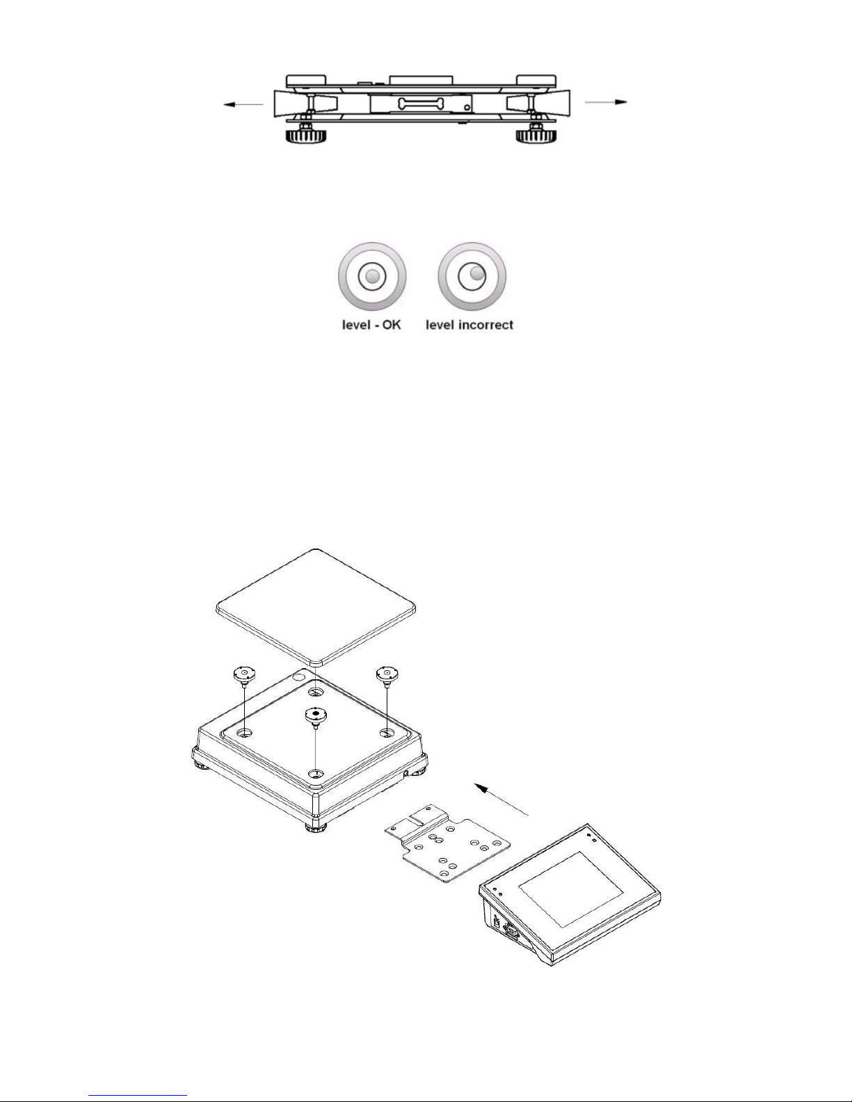
D. Scale should be levelled by turning regulation feet. Levelling is correct
if air bubble is situated in the central position:
4.2. WPY/KTPS/D2 scales
A. Take the device out of the package,
B. Put the scale on an even stiff ground,
C. Fit the pan and the bracket under the device according to the drawing:
7

E. Scale should be levelled by turning regulation feet. Levelling
is correct if air bubble is situated in the central position:
5. SCALE CONSTRUCTION
5.1. Main dimensions
5.1.1. WPY/KTPS/C1 scales
5.1.2. WPY/KTPS/D2 scales
8
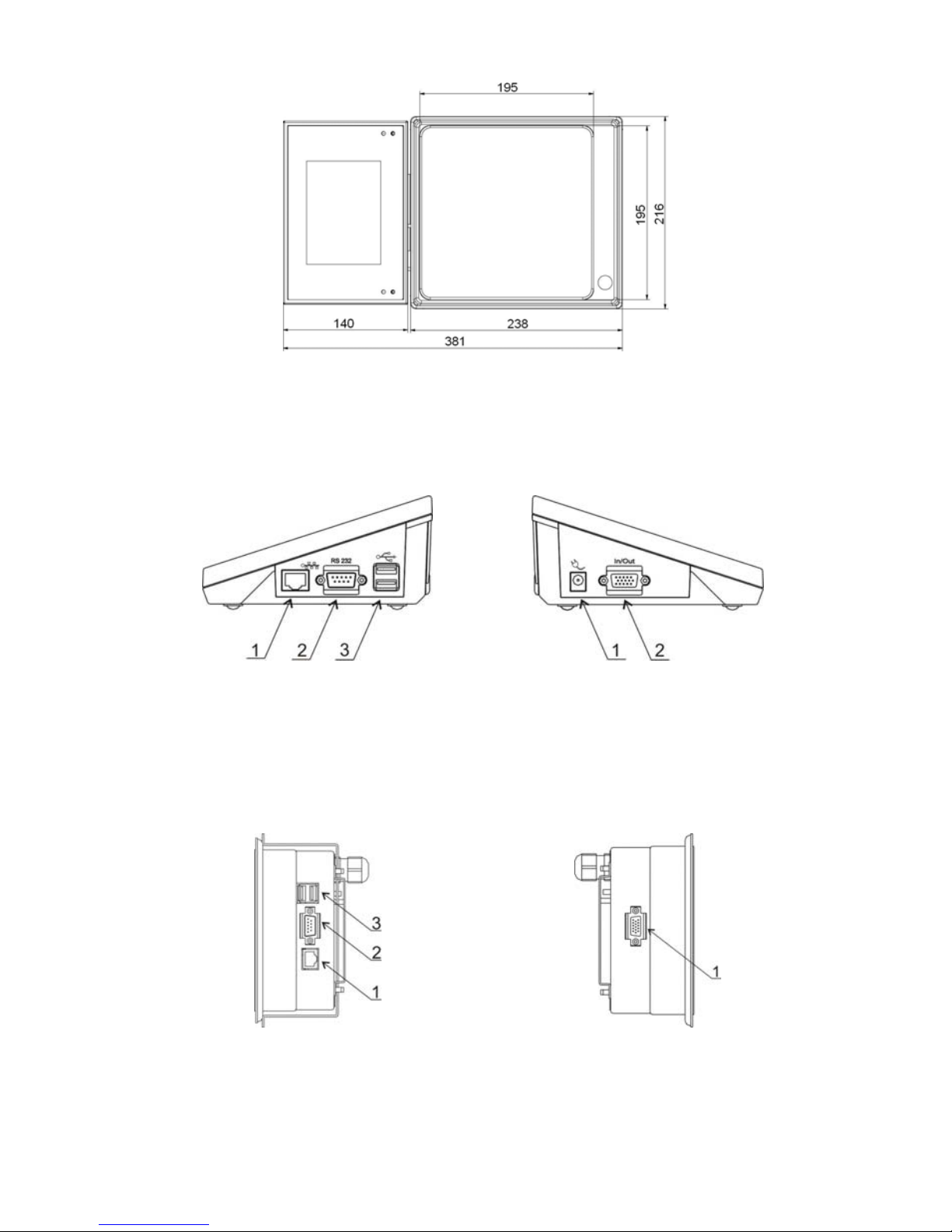
5.2. Description of connectors
5.2.1. Connectors’ description in PUE 7
1 – Ethernet RJ45
2 – RS232 (COM1)
3 – USB
1 – power supply socket
2 – I/O, RS232 (COM2)
5.2.2. Connectors’ description in PUE 7P
1 – Ethernet RJ45
2 – RS232 (COM1)
3 – USB
1 – I/O, RS232 (COM2)
9
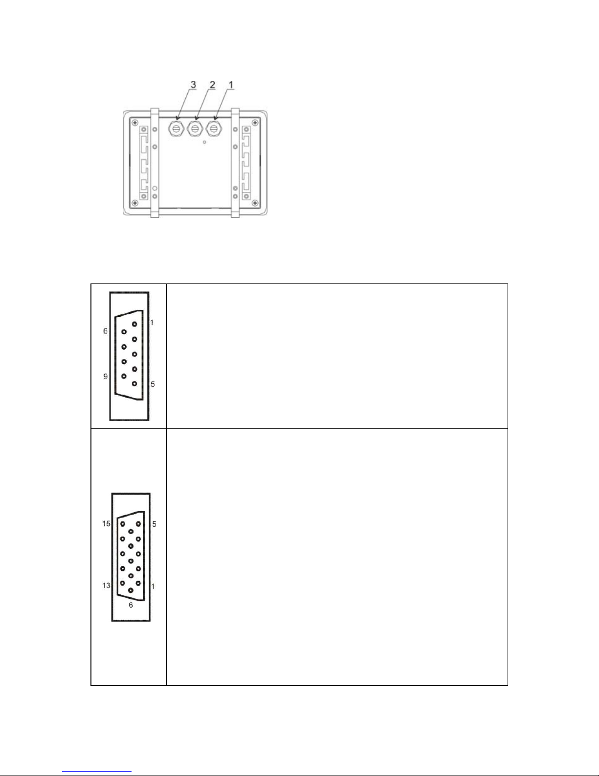
5.2.3. Description of glands PUE 7P
1 – Supply cord gland
2 – Gland for platforms 1, 2
3 – Gland for platforms 3, 4
5.2.4. Connector with RS232 and I/O
RS232 - DB9/M (male),
top view:
Pin2 - RxD
Pin3 - TxD
Pin5 - GND
I/O, RS232 DSUB15/F (female),
top view:
Pin1 - GNDWE
Pin2 - OUT1
Pin3 - OUT2
Pin4 - COMM
Pin5 - 6÷9VDC
Pin6 - IN4
Pin7 - IN3
Pin8 - TxD2
Pin9 - 5VDC
Pin10 - GNDRS
Pin11 - IN2
Pin12 - IN1
Pin13 - RxD2
Pin14 - OUT4
Pin15 - OUT3
10

6. GETTING STARTED
• After the terminal is connected to power the ON/LOAD
diode starts to light.
• Press
to start the operating system loading procedure.
Windows CE together with RADWAG software loading is signalled
by blinking the red diode ON/LOAD.
• When the loading procedure is completed the main software
window appears.
7. KEYPAD OVERLAY
11
8. FUNCTIONS OF KEYS
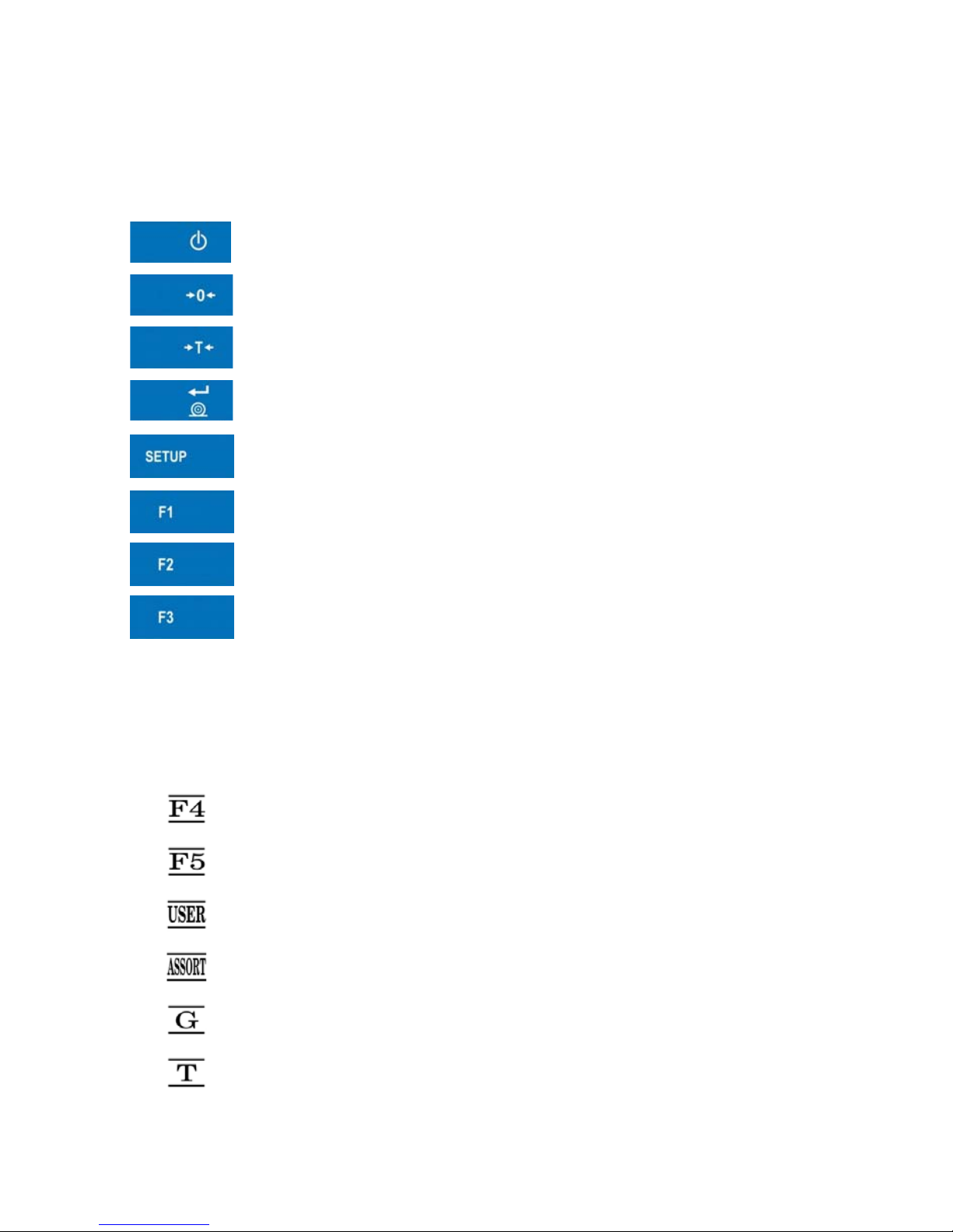
8.1. Keys on the overlay
Key Description
Turning on/off the scale
Zeroing
Tarring
Confirmation of weighing
Entering the scale menu (not active after establishing
a connection with the computer)
Selecting products
Selecting operators
Batch quantity declaration
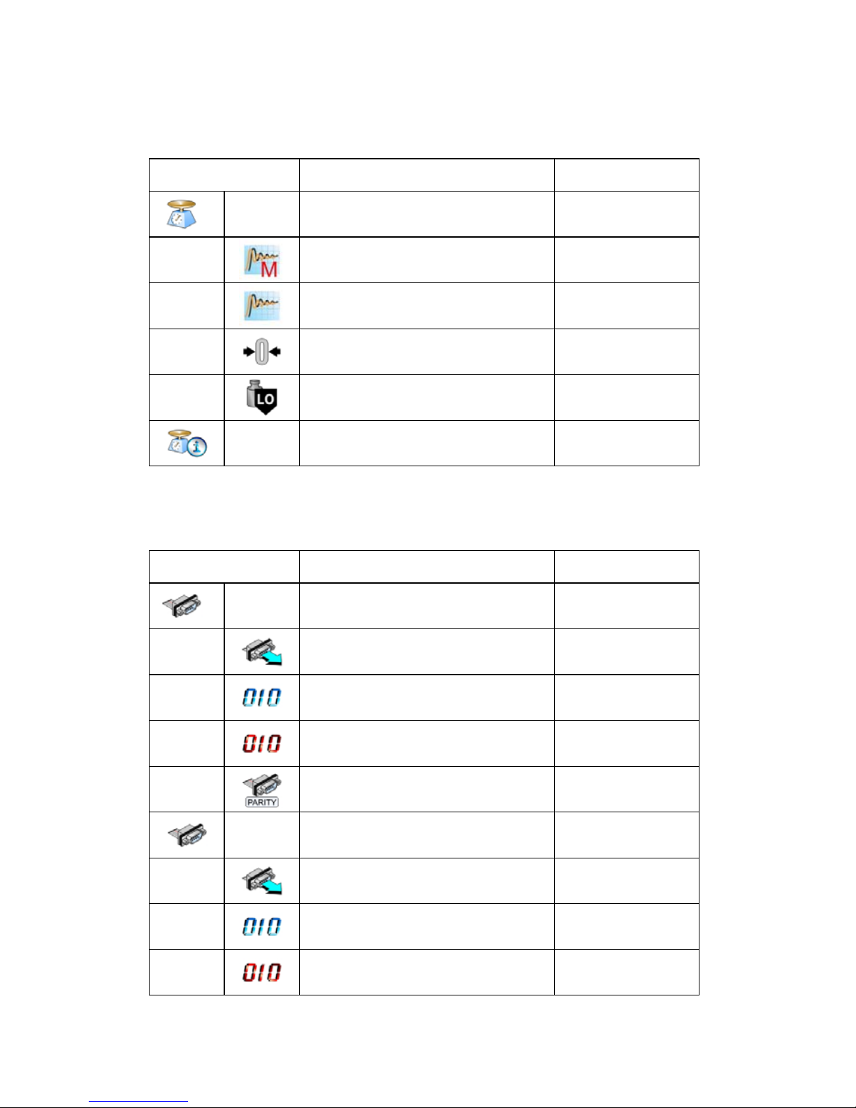
8.2. Screen function buttons
Key Description
Batch number declaration
Starting / completing test controls
Open the list of operators
Open the list of products
Entering density
Starting the procedure of estimating the average tare
12

Moving left the description line for button functions.
Scrolling up the list of operators or products
Moving right the description line for button functions.
Scrolling down the list of operators or products
Leaving the screen displaying the list of operators or
products
9. INDICATING WINDOW
In the main application window one can see four separate parts:
1. The working mode information is displayed in the top part of the display.
It is accompanied by date and time. Additionally following functions are
accessible:
• operator „Logout”,
• show / hide the screen keyboard (button
)
2. Below the status bar you can see weighing windo w(s).:
3. There is a workspace below this window:
• In case of lack of communication with the computer the screen
looks like below:
13
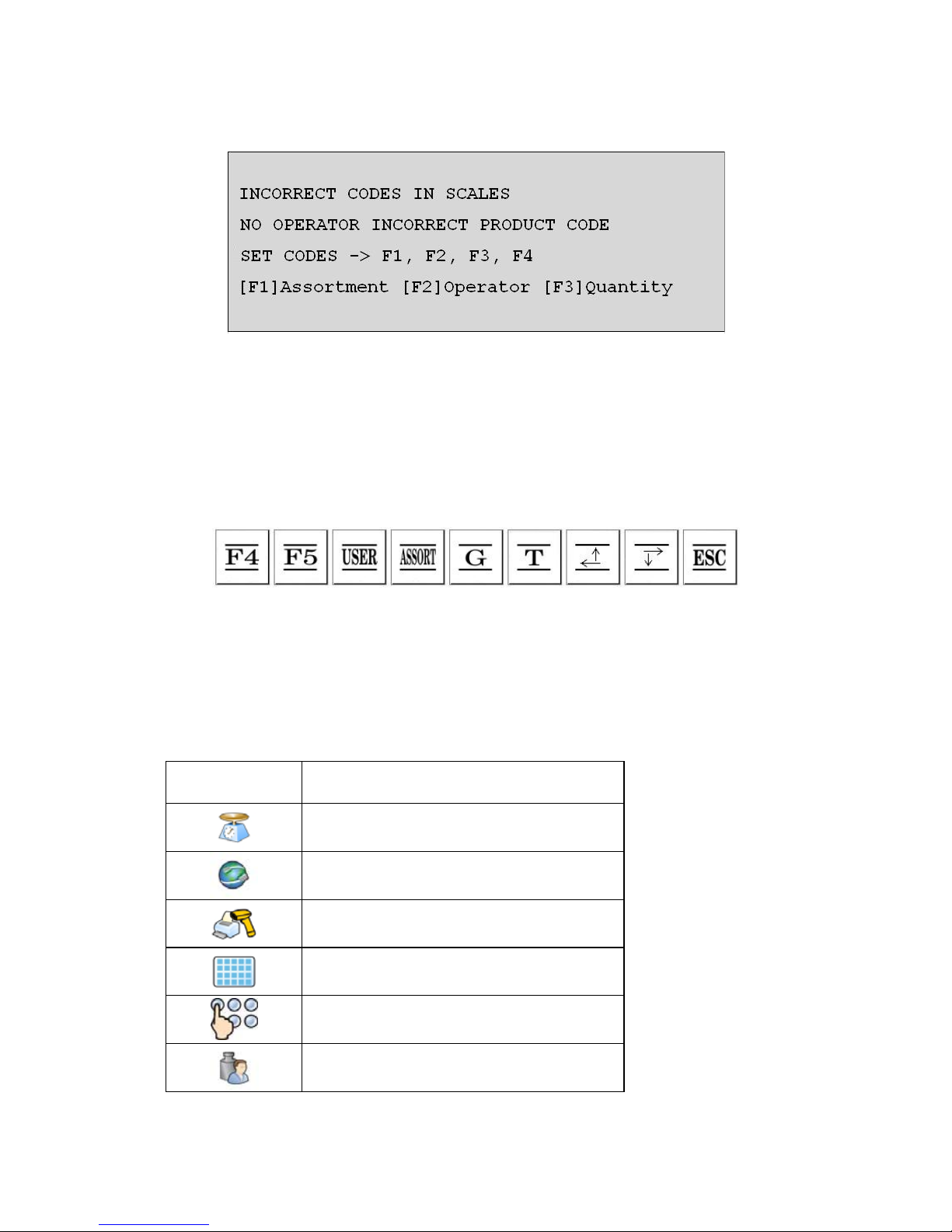
• If a scale establishes connection with the database following
messages are displayed in the workspace:
Notice:
Description of setting codes and cooperation with PC software
KTP NET 2003 can be found in ch. 18 of this manual.
4. There are screen buttons below the workspace (description of button
functions – see ch. 8.2 of this manual)::
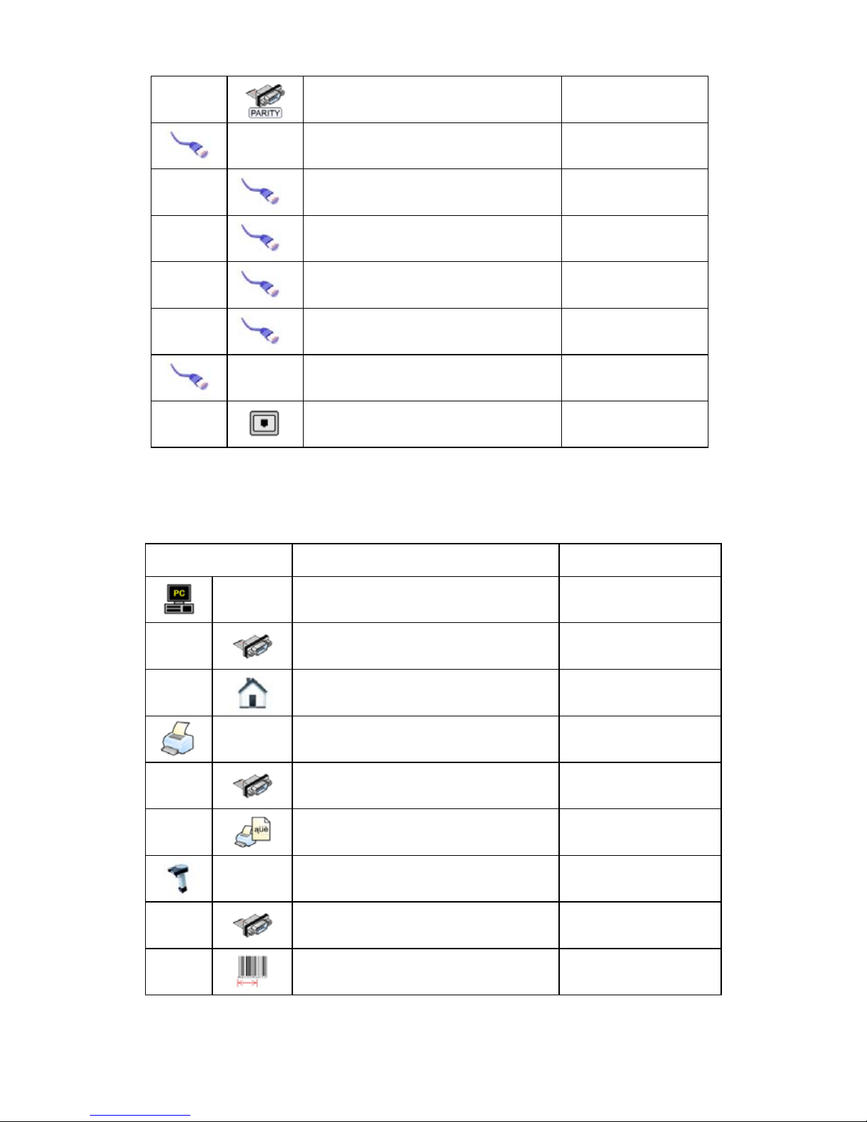
10. PROGRAM STRUCTURE
The main menu has been divided into six functional groups.
In every group there are parameters of similar use.
Icon Description
Scale
Communication
Devices
Display
Other
User Calibration
14
10.1. Inventory of parameters
10.1.1. Scale parameters - weighing
Icon Description Value
Platform 1 -
Median Filter 0.5
Filter Fast
Autozero Yes
LO threshold 0
Weighing software version 2.0
10.1.2. Communication
Icon Description Value
COM1 -
Baud Rate 9600
Data bits 8
Stop bits 1
Parity None
COM2 -
Baud Rate 9600
Data bits 8
Stop bits 1
15
Parity None
Ethernet -
DHCP No
IP Address 192.168.0.2
Subnet mask 255.255.255.0
Gateway 192.168.0.1
Tcp -
Port 4001
10.1.3. Devices
Icon Description Value
Computer
Port None
Address 1
Printer -
Port COM1
Code page 1250
Barcode reader -
Port None
Offset 0
16
 Loading...