

Page 1

R Series Balances
AS R2 Analytical Balances
PS R1 Precision Balances
PS R2 Precision Balances
PS R2.H Precision Balances
APP R Precision Balances
USER MANUAL
IMMU-03-24-06-16-EN
www.radwag.com
Page 2

- 2 -
If you are reading this, it means that you are bound to achieve success. You have purchased
a device that was designed and manufactured to give you years of service.
Congratulations and thank you for selecting RADWAG product.
JUNE 2016
Page 3

- 3 -
TABLE O F CONTENTS
1. General Information .................................................................................... 6
1.1. Dimensions ........................................................................................... 6
1.2. Connectors ............................................................................................ 7
1.3. Connection Cables - Diagrams ................................................................. 7
1.4. PS R2.H Series ....................................................................................... 8
1.5. Intended Use ......................................................................................... 9
1.6. Inappropriate Use .................................................................................. 9
1.7. Warranty ............................................................................................... 9
1.8. Metrological Parameters Monitoring .......................................................... 9
1.9. User Manual Significance ....................................................................... 10
1.10. Balance User Training ........................................................................... 10
2. TRANSPORT and Storage ........................................................................... 10
2.1. Delivery Checklist ................................................................................. 10
2.2. Package .............................................................................................. 10
3. Unpacking and Installation ....................................................................... 10
3.1. Place of Use and Assembling .................................................................. 10
3.2. Unpacking ........................................................................................... 10
3.3. Standard Delivery Components List ........................................................ 11
3.4. Settings .............................................................................................. 13
3.5. Maintenance Activities .......................................................................... 13
3.6. Powering the Device ............................................................................. 16
3.7. Connecting Additional Hardware ............................................................. 16
3.8. Information on the Balance ................................................................... 16
4. Keyboard – Buttons Function .................................................................... 16
5. Start-Up .................................................................................................... 17
5.1. Temperature Stabilization Period ............................................................ 17
5.2. Ambient Conditions State Indication ....................................................... 17
5
.3. User Menu ........................................................................................... 18
5.4. Logging ............................................................................................... 19
5.5. Units................................................................................................... 20
5.6. Temporary Measuring Unit..................................................................... 20
5.7. Units Accessibility ................................................................................. 20
5.8. Start Unit Selection .............................................................................. 21
5.9. Custom Unit ........................................................................................ 21
6. Miscellaneous Parameters ......................................................................... 21
7. Adjustment ............................................................................................... 24
7.1. Internal Adjustment ............................................................................. 24
7.2. Adjustment Menu Settings ..................................................................... 25
7.3. Manual Adjustment ............................................................................... 26
7.3.1. Internal Adjustment .............................................................................. 26
7.3.2. External Adjustment ............................................................................. 26
7.3.3. User Adjustment .................................................................................. 26
7.4. Adjustment Report Printout ................................................................... 27
8. Determini ng Printout Content ................................................................... 27
Page 4

- 4 -
8.1. Adjustment Report ............................................................................... 27
8.2. Header, Footer, GLP Printouts ................................................................ 27
8.3. Non-standard Printouts ......................................................................... 30
8.3.1. Inserting Text ...................................................................................... 30
8.4. Variables ............................................................................................. 32
9. Databases ................................................................................................. 32
9.1. Users .................................................................................................. 33
9.2. Products .............................................................................................. 34
9.3. Tares .................................................................................................. 34
9.4. Weighings ........................................................................................... 34
9.5. ALIBI Memory ...................................................................................... 37
10. Export and Import of Databases................................................................ 38
10.1. Database Esport ................................................................................... 38
10.2. Database Import .................................................................................. 39
10.3. Measurement Data Printout ................................................................... 39
11. Working Modes ......................................................................................... 40
11.1. Working Modes Accessibility .................................................................. 41
11.2. Weighing Operation .............................................................................. 41
11.2.1. Good Weighing Practice ......................................................................... 41
11.2.2. Balance Zeroing ................................................................................... 42
11.2.3. Balance Taring ..................................................................................... 42
11.2.4. WEIGHING Mode Settings ...................................................................... 43
11.2.5. AUTOTARE ........................................................................................... 45
11.2.6. Print Mode ........................................................................................... 45
11.2.7. Information ......................................................................................... 47
11.2.8. Non-Standard Information ..................................................................... 47
11.2.9. F Shortcut Keys .................................................................................... 48
11.2.10. Dual Range Balance (PS 200/2000.R2) ................................................... 49
11.2.11. Under-Pan Weighing ............................................................................ 49
11.3. Counting Parts of the Same Mass ........................................................... 50
11.3.1. PARTS COUNTING Mode Settings ........................................................... 50
11.3.2. Setting t he Reference Mass: Mass D etermination from th e Sample of Known
Quantity 50
11.3.3. Setting the Reference Mass: Entering Mass Value ..................................... 51
11.4. Checkweighing ..................................................................................... 52
11.4.1. Declaring Threshold Values .................................................................... 52
11.5. Dosing ................................................................................................ 53
11.5.1. Setting Target Mass: Entering Mass Value ............................................... 53
11.6. Percent Weighing Control with Relation to Reference Mass ........................ 54
11.6.1. Setting the Reference Mass: Weighing Reference Sample .......................... 54
11.6.2. Setting the Reference Mass: Entering Mass Value ..................................... 55
11.7. Animal Weighing .................................................................................. 55
11.7.1. Additional Settings ............................................................................... 55
11.7.2. Running the Process Manually – Means of Operation ................................. 56
11.7.3. Running the Process Automatically – Means of Operation .......................... 57
11.8. Density of Solids .................................................................................. 57
11.8.1. Density Determination .......................................................................... 59
11.9. Density of Liquids ................................................................................. 60
11.9.1. Density Determination .......................................................................... 61
11.10. Statistics ......................................................................................... 62
11.10.1. Means of Operation .............................................................................. 62
11.10.2. Deleting Statistics ................................................................................ 63
Page 5

- 5 -
11.11. Totalising ........................................................................................ 64
11.11.1. Additional settings ............................................................................... 64
11.11.2. Means of operation .............................................................................. 64
11.12. Peak Hold ........................................................................................ 66
11.12.1. Means of Operation .............................................................................. 66
11.13. Pipettes Calibration .......................................................................... 67
11.13.1. Additional settings of pipettes calibration mode ....................................... 67
11.13.2. Means of Operation .............................................................................. 68
12. Communication ......................................................................................... 71
12.1. RS 232 Ports Settings (COM) ................................................................. 71
12.2. WIFI Port Settings ................................................................................ 71
12.3. Port USB ............................................................................................. 72
13. PERIP H ERAL DEVICES ............................................................................... 75
13.1. Computer ............................................................................................ 75
13.1.1. Computer Connection Port ..................................................................... 75
13.1.2. Continuous Transmission ....................................................................... 76
13.1.3. Printouts Interval for Continuous Transmission ......................................... 76
13.1.4. Cooperation with E2R ............................................................................ 77
13.1.5. Printout ............................................................................................... 77
13.2. Printer ................................................................................................ 77
13.3. Barcode Reader.................................................................................... 79
13.4. Additional Display ................................................................................. 79
13.5. External Buttons .................................................................................. 80
14. Cooperation with Peripherals .................................................................... 80
14.1. Transferred Data Format ....................................................................... 81
14.2. Format of Data Sent on Pressing Print Button .......................................... 81
14.2.1. Response Format ................................................................................. 81
15. Communication Protocol ........................................................................... 82
15.1. List of Commands................................................................................. 82
1
5.2. Responce Format ................................................................................. 83
16. Erro r M e s sages .......................................................................................... 94
17. Additional Ecquipment .............................................................................. 94
Page 6
- 6 -
1. GENERAL INFORMATION
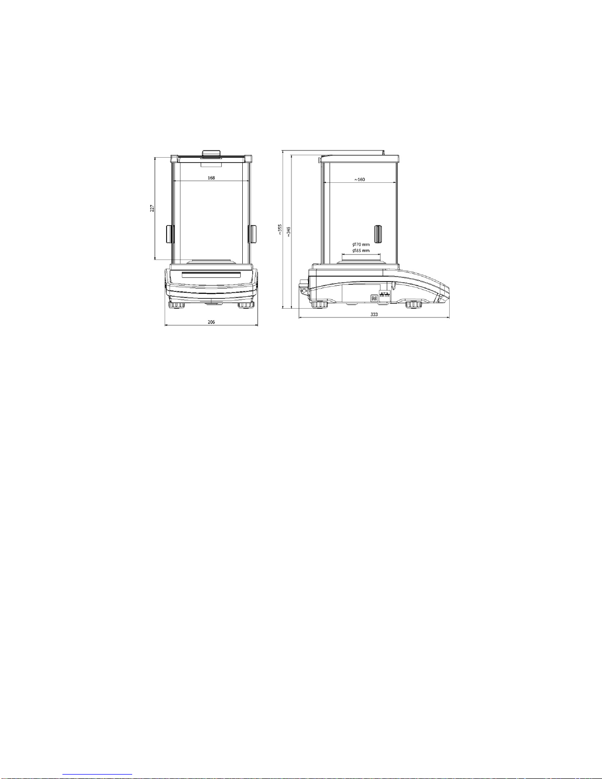
1.1. DIMENSIONS
AS series:
PS series with pan 128 x 128 mm:
PS series with pan 195 x 195 mm:
APP series:
Page 7
- 7 -
1.2. CONNECTORS
1
Power supply socket
2
COM 2 connector (additional display or external buttons)
3
COM 1 connector (printer)
4
USB 2, type B (computer)
5
USB 1, type A (keyboard)
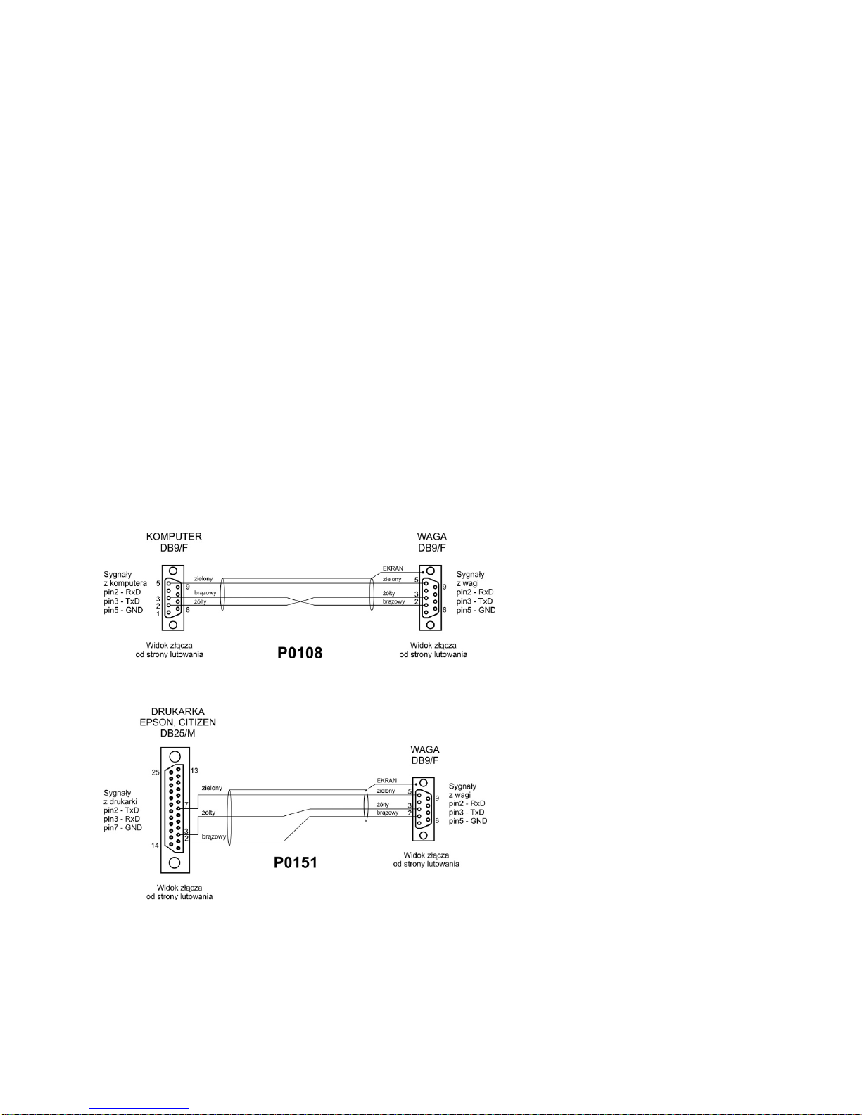
1.3. CONNECTION CABLES - DIAGRAMS
Scale – computer cable (RS232)
Scale – printer cable (CITIZEN, EPSON)
Page 8
- 8 -
1.4. PS R2.H SERIES
PS R2.H series redefine the level of standard for precision balances. Not only do they share all the
features of R series balances, but can also work in adverse operating conditions (condensed dust,
drops of water falling down at different angles) typical for IP 54.
PS.R2.H balances are offered with round pans of two possible sizes: ø115mm and ø170mm.
Balances with pans of a smaller size feature draft shield as well.
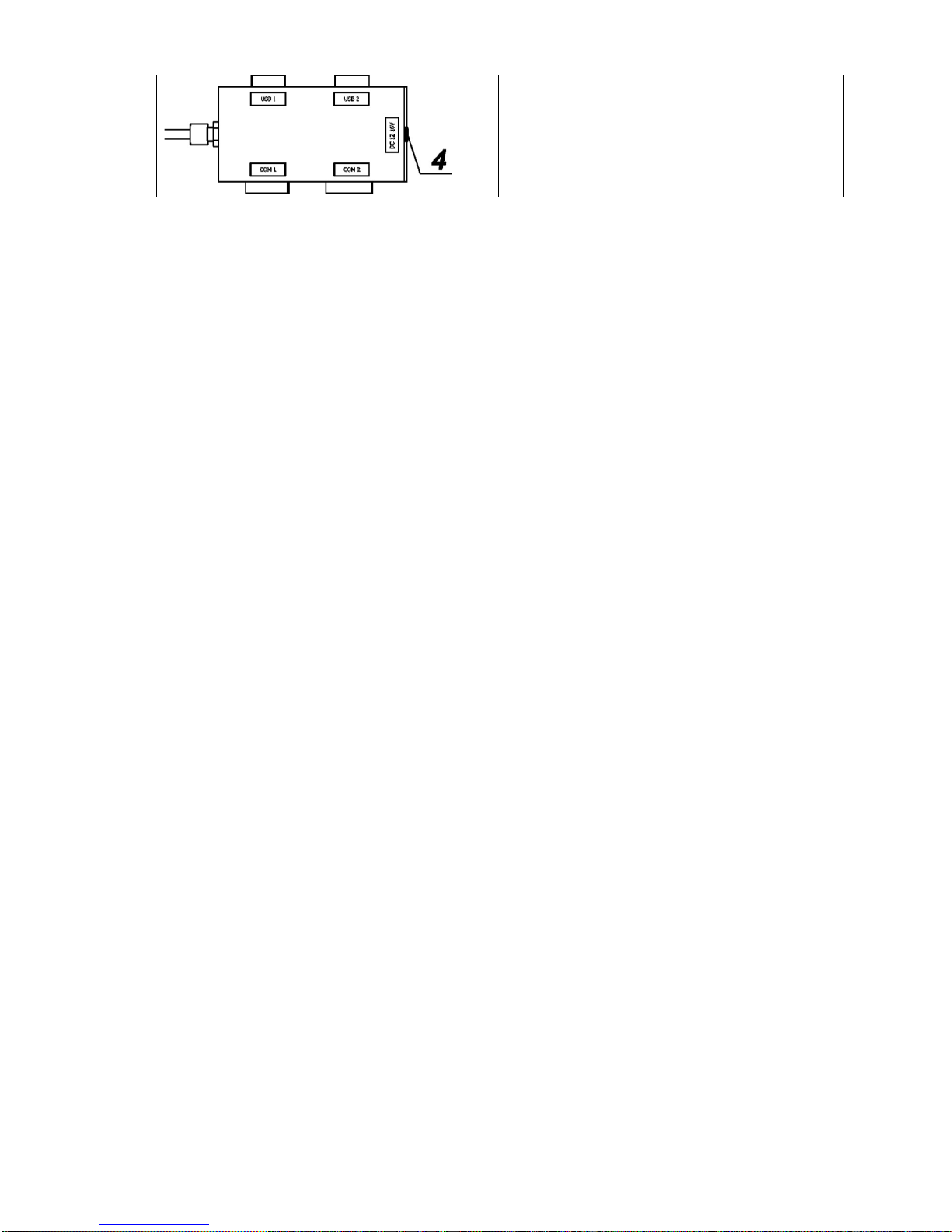
Additional asset of PS R2.H balances are their interfaces build-in a hermetic closed housing which is
separated from the balance. The interfaces include 2×RS 232, USB type A, USB type B, and Wi-Fi
optionally.
Balance housing is made of plastic, whereas its pan of stainless steel.
PS R2.H series metrological parameters are identical like those of standard design balances.
Balance with pan Φ 115 mm
Balance with pan Φ 170 mm
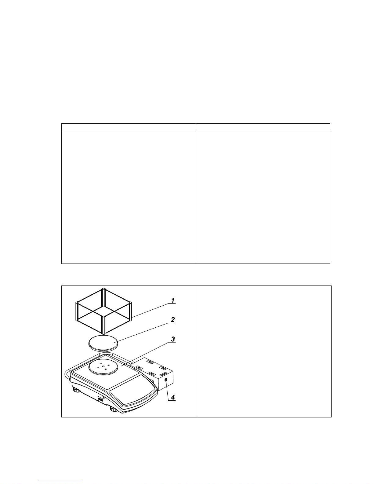
Balance assembly
Upon unpacking the balance remove any
protective elements and assembly the
balance:
Install:
• metal weighing pan (2)
• draft shield (1), for balances with pan Φ
115 mm
• plug a power supplier connector into the
port of interfaces housing
• plug the power supplier into the mains
Page 9
- 9 -
CAUTION!
While cleaning it is a dv is ab le t o fo llow be low prec aut io ns . Ad dit io nally i t is a m us t to d is c onnect the device from
mains and unplug a ll the peripherals (print ers , c omp ut er et c.) remembering at the s ame ti me t o pr otec t por ts by
means of stoppers. Only t hus prepared device can be c leaned. Upon completion of th e cleaning process the
device may be connected to mains for further operation.
1.5. INTENDED USE
X2 series balances are designed to provide accurate measurement of weighed loads, performed
under laboratory conditions. It is intended for application as a non-automatic weighing instrument
only, i.e. the material to be weighed is manually and carefully placed in the centre of the weighing
pan. Weighing result should be read only after stable reading has been obtained.
1.6. INAPPROPRIATE USE
Do not use the balance for a dynamic weighing. Even if small quantities of weighed material are
added or removed from the weighing pan of the instrument, the reading should be taken only after
stabilisation of the measurement results. Do not place any magnetic materials on the weighing pan,
as this can cause damage to the measuring system of the instrument.
Be sure to avoid impact shock and overloading the balance in excess of the prescribed maximum
measuring range (max capacity), minus any possible tare weight that has been applied.
Never use the balance in an environment where explosion is possible. This balance has not been
adjusted for operation in explosive areas.
There must not be any modification made to the balance.
1.7. WARRANTY
Warranty is invalid for the following:
•
non-observation of the guidelines of this user manual,
• use of the balance other than specified in this manual,
• alteration to or opening of the device,
• mechanical damage and damage caused by media, water, wear and tear,
• inappropriate assembling or defects of electric installation,
• overloading of the measuring instrument.
1.8. METRO LOG ICAL PARAMETERS MONITORING
Metrological characteristics of the balance require periodical inspection to be carried out by its user.
Inspection frequency is dependent on ambient conditions in which the balance is used, types of
performed processes and accepted quality management system in organization.
Page 10

- 10 -
1.9. USER MANUAL SIGNIFIC ANCE
It is very important to read the user manual carefully before switching on and starting up balance
operation, even if the user is experienced and has worked with this type of balance before.
1.10. BALANCE USER TRAINING
The balance should be utilized and supervised only by users who are trained and experienced in
using such type of weighing instruments.
2. TRANSPORT AND STORAGE
2.1. DELIVERY CHECKLIST
Upon delivery it is necessary to check the package and the device, make sure that your package
bears no signs of damage.
2.2. PACKAGE
Keep all package elements should your device be transported in a future. Remember that only
original packaging can be used for shipping purposes. Prior packing uncouple any cables, remove
any separable components (weighing pan, shields, inserts). The device components shall be packed
into an original packaging, thus being protected against potential damage during transportation
3. UNP A CKING AND INST A LLATION
3.1. PLACE OF USE AND ASSEMBLING
• The balance should be stored and used in locations free of vibrations and shakes, free of air
movement and dust,
• ambient air temperature should not exceed the range of: +10 °C ÷ +40 °C,
• ambient relative humidity should not exceed 80%,
• during balance operation, ambient temperature in the weighing room should not change rapidly,
• the balance should be located on a stable wall console desk or a stable working table which is
not affected by vibrations and distant from heat sources,
• take special precaution when weighing magnetic objects, as part of the balance is a strong
magnet. Should such loads be weighed, use under-pan weighing option, which removes the
weighed load from area influenced by the balance’s magnet. The hook for under-pan weighing
is installed in balance’s base,
• in order to avoid the influence of static electricity on the measurement process, ground the
balance’s housing. The grounding bolt is located at the back of the balance’s housing.
3.2. UNPACKING
Cut the adhesive tape. Take the device out of the packaging. Open the accessory box, take the
device components out of it.
Page 11

- 11 -
3.3. STANDARD DELIVERY COMPO NENTS LIST
• balance
• bottom insert (AS balance exclusively)
• centring ring (AS balance exclusively)
• weighing pan, open-work pan for AS with d=0,01/0,1mg exclusively
• draft shield (AS and PS balances, d=0.001g, exclusively).
• power supplier
• user Manual – CD version
AS balance, d=0.01/0.1 mg
AS balance, d=0.1 mg
•
remove a transport lock (1) – gently press the transport lock and turn it accordingly to
<OPEN> instruction, ke
ep the transport lock should your balance be transported in the
future.
• Install components following the above diagram:
• bottom insert (2),
• centring ring [embossment side up] (3),
• weighing pan (4),
• draft shield (5).
Page 12

- 12 -
PS balance, d=0.001g PS balance, d=0.01g
•
remove tape protecting the grounding spring, located on one of the rubber mandrels (1)
• install components following the above diagram:
• weighing pan (2),
• glass draft shield (3).
APP balance
APP 10.R1 and APP 10.R2 balances are equipped with 2 weighing pans which can be used in t urns.
It must be remembered that balance activation is only possible with one weighing pan assembled at
a time. Attempt of activating the balance with two weighing pans assembled simultaneously will result
in display of „– LH –„ error. In such case one of the pans needs to be removed.
Remove the weighing pan, next remove a transport lock (if
installed).
For APP.R2 series undo bolt (1) installed to block adjustment
mechanism.
Install a weighing pan (for APP 10.R install one of the pans).
Make sure the weighing pan is placed properly on shock
absorbers: the weighing pan cannot touch the housing and
should be stable
Connect an indicator using port located at the back, next
connect supplementary equipment.
Now, connect the device to the mains (power supply socket is
located at the back).
Page 13

- 13 -
3.4. SETTINGS
It is necessary to level the balance prior connecting it to the mains. To level the
balance turn its feet until an air bubble takes the central position.
After adjusting the balance level, use a wrench (3) in order to screw a bolt (2) of foot (1), the bolt shall
touch balance housing, keep screwing until the bolt resists. Repeat this set of actions for the
remaining balance feet.
The balance shall rest on a surface firmly, each of the feet must be supported.
3.5. MAINTE N ANCE ACTIV ITI ES
1. Disassembly a weighing pan and other detachable components (the components differ
depending on a balance type – see Unpacking section). Be careful while detaching the
components so as not to cause any damages to the balance mechanism.
2. Using a dry flannel cloth clean glass parts (mild cleanser may be applied if it does not contain
any abrasive substances) – draft shield disassembly instruction is to be found further down this
section.
3. Using a dry flannel cloth clean disassembled components (mild cleanser may be applied if it
does not contain any abrasive substances).
CAUTION!
Cleaning draft shield while still installed may cause damage of the measuring system.
Cleaning ABS components:
To clean dry surfaces and avoid smutching use clean non-colouring cloths made of cellulose or
cotton. You can use a solution of water and detergent ( soap, dishwashing detergent, glass cleaner).
Gently rub the cleaned surface and let it dry. Repeat cleaning process if needed.
In the case when contamination is hard to remove, e.g. adhesive, rubber, resin, polyurethane foam
residues etc., you can use a special cleaning agents based on a mixture of aliphatic hydrocarbons
that do not dissolve plastics. Before using the cleanser for all surfaces we recommend carrying out
tests. Do not use products containing abrasive substances.
Cleaning glass components:
Select dissolvent depending on a dirt. Never soak the glass panes in alkaline solutions since they
interact with glass and may cause damage. Do not use abrasive substances.
For organic dirt use acetone first, next use water or detergent. For other than organic dirt use diluted
acid solutions (soluble salts of hydrochloric or nitric acid) or base solutions (ammonium or sodium
base).
To remove ACIDS use protofilic solvent (sodium carbonate), to remove BASE use protogenic solvent
(mineral acid of various concentration).
Page 14

- 14 -
In case of heavy contamination use brush or detergent nevertheless avoid detergents containing
large and hard molecules which could potentially scratch glass panes.
Use soft brush with wooden or plastic handle exclusively to avaoid risk of scr atches. Do not use wire
brush.
At the end of the cleaning process rinse the pane using running water first, distilled next.
Rinsing is a necessary cleaning process stage allowing to remove remaining soap, detergents and
other cleansers from the panes prior their reinstallation.
Avoid drying the panes either using paper towel or for ced air circulation since some fibr es, grains or
contamination of other type could permeate into the panes thus causing weighing errors.
One shall not use driers when drying measuring glass tools.
It is a frequent treatment to leave glass components on a rack to dry.
Cleaning stainless steel components:
Avoid using cleansers containing any corrosive chemicals, e.g. bleach (containing chlorine). Do not
use abrasive substances. Always remove the dirt using microfiber cloth to avoid damage of protective
coating.
In case of a daily maintenance:
1. Remove the dirt using cloth dipped in warm water.
2. For best results, add a little dishwashing detergent.
Cleaning powder-coated components:
For preliminary cleaning stage you need running water or wet sponge featuring large wholes, this w ill
help you to remove loose, heavy dirt.
Do not use cleansers containning abrasive substances.
Next using cloth and cleanser-water solution (soap, dishwashing liquid) gently rub the cleaned
surface.
Avoid using cleanser without water since it may result with damage of the cleaned surface, please
mind that large amount of water mixed with cleanser is a must.
Cleaning aluminium components:
While cleaning aluminium components use products acid by nature, e.g. spirit vinegar, lemon. Do not
use abrasive substances. Avoid using hard brush, this may caus e scratches. It is recommended to
use microfibre cloth.
While polishing the surface use circular movements. Use clean, dry cloth.
In order to ease cleaning of glass draft shield panes, it is permissible to remove them following the
below instruction.
AS series – sequence of actions:
Page 15

- 15 -
Undo and remove top pane
protection, next slide the pane out of
a guide bar.
Remove the back pane.
Remove side panes.
Side panes shall not be swapped
therefore it is necessary to remember
which one is right, and which one is
left in order to install them back
properly.
CAUTION! Do not remove the front pane!
Remove a weighing pan, a draft
shield, a bottom insert. Clean the
components when detached. With this
your balance mechanism is protected
against accidental damage.
Thus prepared draft shield and panes can be properly cleaned. All the operations should be done
carefully. Pay special CAUTION to the spot where the weighing pan was installed: dirt and other
small elements might enter the balance construction through this opening, which might negatively
influence the balance parameters.
Page 16

- 16 -
3.6. POWERING THE DEVICE
Balance can be connected to the mains only with a power adapter that comes standard with
the particular model. Nominal power supply of the power adapter (specified on the power
adapter data plate) should be compatible to the power from the mains.
Plug the balance to the mains – connect the power adapter to the socket, next connect its connector
to port located at the back of the balance housing.
Test of the display unit takes place right after c onnecting the balance to the power, all the elements
and pictograms are backlit for a short time. Next, the name and the program number appears, the
indication gets to ZERO (displayed reading unit depends on the balance). During t he balance start,
the test of an internal mass adjustment mechanism occurs (single location and elevation of the
internal mass adjustment).
If the indication is different than zero, please press
button.
CAUTION!
If the balance is “verified”, automatic adjustment occurs right after switching the balance on.
3.7. CONNECTING ADDITIONAL HAR DWARE
Use only accessories and peripheral equipment recommended by the manufacturer. The balance
must be disconnected from the mains before connecting or disconnecting any peripherals (printer,
PC computer, computer keyboard). On connecting the peripherals, plug the balance to the mains.
3.8. INFORMATION ON THE B ALANCE
<INFO> menu provides information on the balance: balance type, software version, internal
temperature of the balance. The parameters are strictly informative.
<SETUP PRNT.> parameter has been designed to enable sending balance settings to printer (all
parameters).
4. KEYBOARD – BUTTONS FUNCTION
Press to switch the balance ON/OFF. If switched off, balance
components other than the display are powered, and balance is in
stand-by mode.
F9 button of the computer keyboard.
Press to access data stored in a database: user, product, tare.
F10 button of the computer keyboard.
Press to enter directly the active working mode settings.
F11 button of the computer keyboard.
Page 17

- 17 -
Press to select working mode.
F5 button of the computer keyboard.
Press to change measuring units.
PRINT/ENTER button
Press to send measurement to a printer or a computer (PRINT).
Press to confirm selected parameter value or function (ENTER).
Press to Zero the balance
Press to Tare t he balance
Press to start adjustment / calibration process immediately.
F6 button of the computer keyboard.
Press to enter the main menu of a balance.
F7 button of the computer keyboard.
Press to operate balance menu or change parameter value.
5. START-UP
When plugged to mains, the balance displays program name and number, next it proceeds to the
weighing mode.
5.1. TEMPERATURE STABILIZATION PERIOD
Before start of measuring processes, it is necessary to wait until the balance reaches thermal
stabilisation.
For balances that were stored in much lower temperatures before plugging to mains (e.g. during
winter period), thermal stabilisation period shall take at least 4 hours for PS balances, and 8 hours for
AS and APP balances. During the thermal stabilization, the indications on the display panel can
change.
It is recommended that ambient temperature changes at place of use were insignificant (slow to
change).
5.2. AMBIENT CONDITIONS ST ATE INDICATION
The function is intended to inform on unstable ambient conditions for a balance, it is enabled only for
AS R series balances.
The function controls dynamic temperature changes occurring in the balance during its operation. If
the variation is greater than set limit values (temperature changes speed), then a blinking
thermometer pictogram is displayed on the screen.
Page 18

- 18 -
The blinking thermometer pictogram means that temperature inside the balance is not stable, this
may result in inaccurate mass measurement. For such a case it is recommended to wait until the
temperature stabilizes or to perform balance adjustment (blanking of the blinking thermometer
pictogram).
5.3. USER MENU
Menu is divided into 9 basic function groups. Each group has an individual name starting with
a capital letter, P.
P1 ADJUSTMENT
P1.1
INT. CALIB.
|
[internal adjustment]
P1.2
EXT. CALIB.
|
[external adjustment]
P1.3
USER CALIBRATION
|
[user adjustment]
P1.4
CALIBRATION TEST
|
[adjustment test]
P1.5
AUTO. CALIB.
|
[automatic adjustment]
P1.6
AUTO. CALIB. C.
|
[time of automatic adjustment]
P2 WORKING MODES
P2.1
ACCESSIBILITY
|
[settings for the accessibility of
individual modes
while working with the balance]
P2.2
WEIGHING
|
[setting for the function weighing]
P2.3
COUNTING PCS
|
[settings for the function counting pieces]
P2.4
CHECKWEIGHING
|
[settings for the function checkw eighing]
P2.5
DOSING
|
[settings for the function dosing]
P2.6
DEVIATIONS
|
[settings for the function deviations % against
the mass of the standard]
P2.7
DENS. OF SOLIDS
|
[settings for determining density of solids]
P2.8
DENS OF LIQUIDS
|
[settings for determining density of liquids]
P2.9
ANIMAL WEIGHING
|
[settings for the function animal weighing]
P2.10
STATISTICS
|
[settings for the function statistics]
P2.11
TOTALISING
|
[settings for the function totalising]
P2.12
PEAK HOLD
|
[settings for the function peak hold]
P2.13
PIPETTES CALIB.
|
[settings for the function pipettes calibration]
P3 COMMUNICATION
P3.1
COM1
|
[transmission parameters port COM 1]
P3.2
COM2
|
[transmission parameters port COM 2]
P3.3
WIFI
|
[transmission parameters port WIFI ]
P4 DEVICES
P4.1
COMPUTER
|
[PC connection port]
P4.2
PRINTER
|
[printer connection port]
P4.3
BARCODE READER
|
[barcode connection port]
P4.4
ADD.DISPLAY
|
[additional display port]
P4.5
EXT.BUTTONS
|
P5 PRINTOUT
P5.1
CAL. REPORT
|
[contents of the adjustment report]
P5.2
HEADER
|
[contents of the header printout]
P5.3
GLP PRNT.
|
[contents of the weighing result prnt.]
P5.4
FOOTER
|
[contents of the footer printout]
P5.5
NSD.PRN.1
|
[project of non-standard printout 1]
P5.6
NSD.PRN.2
|
[project of non-standard printout 2]
P5.7
NSD.PRN.3
|
[project of non-standard printout 3]
Page 19

- 19 -
P5.8
NSD.PRN.4
|
[project of non-standard printout 4]
P5.9
VARIABLE1
|
[project of variable 1]
P5.10
VARIABLE2
|
[project of variable 2]
P6 OTHER
P6.1
LANGUAGE
|
[menu language]
P6.2
ACCESS LEV.
|
[access levels for editing menu]
P6.3
KEY SOUND
|
[key sound]
P6.4
BACKLIGHT
|
[display backlight level]
P6.5
STAND-BY MODE
|
[backlight turn-off time interval]
P6.6
AUTO OFF
|
[display turn-off time interval]
P6.7
DATE
|
[date settings]
P6.8
TIME
|
[time settings]
P6.9
DATE FORM.
|
[date format]
P6.10
TIME FORM.
|
[time format]
P6.11
GLP AUTOTEST
|
[carrying out autotest for the balance]
P7 INFO
P7.1
BALANCE ID
|
P7.2
SCALE TYPE
|
P7.3
PROG.VER.
| P7.4
TEMP.
|
P7.5
SETUP PRNT.
|
P8 UNITS
P8.1
ACCESSIBILITY
|
[declaration of units to be available for balance
operation]
P8.2
START UNIT
|
[selection of a start unit, unit active on balance startup]
P8.3
USER UNIT U1
|
[parameter defining user’s unit 1]
P8.4
USER UNIT U2
|
[parameter defining user’s unit 2]
P9 IMPORT/EXPORT (parameter displayed upon inserting t he USB flash drive to the balance)
IE1
EKSPORT
|
[data export]
IE2
IMPORT
|
[data import]
CAUTION!
Balance memory modifications will be saved upon abandoning the menu (on return to weighing).
Press ESC button several times.
5.4. LOGGING
In order to have full access to user parameters and be enabled to edit databases, the balance
operator should log in as <ADMINISTRATOR> each time running the balance. The software enables
the entry of 100 users with various access rights.
First Log In operation - procedure:
• Run home screen and press butt on, next select <LOG IN> option, operators database
window opens with list of available users, or press function button with <LOG IN> function
assigned, or press
button, enter users database and select <ADMIN> user.
• Press button for confirmation, wait to be asked for a password.
• Enter the password: „1111”, next press for confirmation.
Page 20
- 20 -
• Home screen of the software is displayed again automatically.
• When logged, add users and set the permissions levels (for the procedure of assigning
permissions levels read section 9.1).
On future Logging In, select a user from the list and enter the password, the software initiates
operation with permissions level set for the selected user.
If any user is logged in, a pictogram
is displayed.
Log out operation – procedure:
•
Select <NONE> position out of the list of available users
• Home screen of the software is displayed again, and the display shows no log ged-in user (no
logged-in user, no pictogram
on the display).
5.5. UNITS
UNITS parameter group enables the user to change availability of mass units (the change can be
performed in-course of balance operation), and to define two custom units, thus positively effecting
comfort and speed of operation. It is possible to change unit to other than unit [g] during weighing
process or during operation of other modes. Working modes Parts Counting and Percent Weighing
are exceptions.
5.6. TEMPORARY MEASURING UNIT
Function enables selecting a measuring unit which is to be indicated next to mass reading during the
operation. The set measuring unit will be in use from the moment of its activation until its change or
switching the balance off and on.
Each pressing of the
button results with change of the measuring unit.
Options:
• For verified balances, you can select from the following: [g], [mg] or [kg], [ct]
• For non-verified balances, you can select from the following: [g], [mg], [kg], [ct], [lb], [oz], [ozt],
[dwt], [tlh], [tls], [tlt], [tlc] , [mom], [gr], [ti], [N]
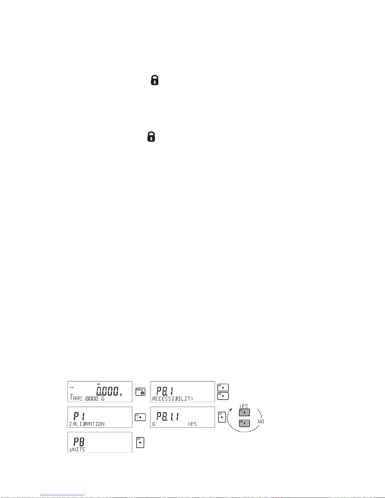
5.7. UNITS ACCESSIBILITY
By pressing button
, the user may declare units to be available for selection of temporary unit.
Units with parameter value set to <YES> are available for selection in specified operating modes.
Procedure:
Page 21

- 21 -
5.8. START UNIT SELECTION
Upon selection of start unit, the balance activates with the specified unit for these modes where
change of the unit is possible.
Ability of selecting a given unit depends on the balance status, i.e. if the balance is verified or not.
Procedure:
5.9. CUSTOM UNIT
You can declare two custom units. The custom unit is a result of indication multiplied by a specified
coefficient.
The units are displayed as [u1] – user unit 1, and [u2] – user unit 2.
Procedure for declaration of coefficient for the custom unit:
Custom units are valid for verified balances exclusively.
6. MISCELLANEOUS PARAMETERS
You can set up par ameters which influence balance operation. These parameters are to be found in
parameters group P6 OTHER.
Settings modification for particular parameters of this parameter group proceeds likewise as
described in the previous section.
Menu language
Language parameter enables selecting the language of the balance menu descriptions.
Available languages: POLISH, ENGLISH, GERMAN, SPANISH, FRENCH, TURKISH, CZECH,
ITALIAN, HUNGARIAN.
Permissions
Permissions parameter enables choosing access level for a particular user, one that is not logged in.
Page 22

- 22 -
Available access levels: ADMIN. / USER. / ADV.
Depending on selected permissions level, you can enter balance parameters and modify the settings,
as far as possible for a particular level (for permissions overview read point 9.1).
„Beep” sound – reaction to operation of pressing a key
Sound parameter enables switching on/off a ‘beep’ sound responsible for informing a user about
pressing any key of balance overlay.
NO - ‘beep’ sound off
YES - ‘beep’ sound on.
Backlight, and display brightness adjustment
The parameter enables setting the brightness of the backlight or switching off the display brightness
completely.
100 - maximum brightness of the backlight
10 - minimum brightness of the backlight
NONE - display brightness switched off
Backlight turn-off time
Parameter <P6.5 STAND-BY MODE> enables use of function responsible for activation of the
display stand-by mode when weighing process is not being performed (stable indication is a
necessary condition for activation of the stand-by mode).
NONE – backlit turn-off time not activated
0.5; 1; 2; 3; 5 – time given in minutes
If the software registers stable indication for a specified time interval, set in parameter <P6.5 STANDBY MODE>, than the display goes out immediately.
The backlight activates upon change of indication (no stability pictogram on the display) or pressing
any key on the balance keypad. Blanking works also when balance menu is entered.
Auto switch-off
Parameter <P6.6 AUTO OFF> enables use of function responsible for automatic display deactivation
(functions as
button). Upon display deactivation the other subassemblies are powered and the
balance turns to stand-by mode.
NONE – auto switch-off not activated
0.5; 1; 2; 3; 5 – time given in minutes
If the software registers stable indication for a specified time interval, set in parameter <P6.6 AUTO
OFF> settings, than the display is turned-off immediately (inactive backlight function, no indication on
the display, clock displayed).
To start-up the balance it is necessary to press
button located on the balance keypad. The
balance will automatically return to weighing.
The balance cannot be turned off if any process is started or if balance menu is entered.
Date
Date parameter enables setting the current date.
Procedure:
Time
Date parameter enables setting the current time.
Procedure:
Page 23

- 23 -
Date format
Date form. parameter enables altering the date format on the printout [YYYY.MM.DD / YYYY.DD.MM
/ DD.MM.YYYY / MM.DD.YYYY], where: YYYY – year; MM – month; DD – day.
Time format
Time form. parameter enables specifying time format for a printout [12h / 24h].
For [12h] option selected, <A> or <P> letter is displayed next to presented time value, where: A
stands for hours before noon; P stands for hours after noon. On the printout AM and PM symbols are
placed right next to the time.
GLP autotest
AUTOTEST function is designed to aid a user in assessing balance’s operation and diagnosing the
reasons for occurrence of errors in weighing which exceed the maximum permissible values for a
given balance model.
By means of a simple, repeatable and fully documented way, the function enables optimizing
balance’s settings to maintain the best possible repeatability and weighing time at workstation. The
main purpose of the function is the possibility of monitoring the above-mentioned parameters at
optional moment and saving records from the carried out tests in the form of printed reports of the
tests that are automatically generated at the end of examination.
The test controls repeatability of placing the interval weight and det ermining error of indication wit h
reference to balance’s maximum capacity.
Testing procedure:
• deposit internal weight twice,
• deposit internal weight ten times,
• calculate the value of standard deviation,
• perform balance adjustment,
• pr int a report.
Test results provide balance data, calculated error for Max capacity and value of repeatability of
indication expressed as standard deviation.
An exemplary report:
.....................................................
--------- Autotest GLP: Report ---------
Balance type PS 3000.R2
Balance ID 400010
User Admin
Software ver. v.0.4.9
Date 2013.07.16
Time 09:17:16
----------------------------------------
Number of measurements 10
Reading unit 0.001/0.01 g
Internal weight mass 1402.094 g
Filter Average
Value release Fast &Reliable
----------------------------------------
Deviation for Max. -0.118 g
Repeatability 0.0088 g
Signature
........................................
Page 24

- 24 -
Procedure:
To initiate parameter <P6.11 GLP AUTOTEST > press
button. The balance software launches
the GLP autotest procedure and it is carried out automatically from now on to the end.
You can stop the procedure at any time by pressing
button of the GLP process window.
Once the procedure is finished, the value of standard deviation of all measurements is shown in the
main display, and message <RESULT> in the bottom line, the final report is printed out automatically
(as shown above). It is possible to print out the report again by pressing
button.
Report is not saved, therefore when abandoning this level, it is deleted from the balance volatile
memory.
To abandon the window press
button and the program returns to the main menu. To r eturn to
weighing, press
button repeatedly.
7. ADJUSTMENT
In order to ensure the highest weighing accuracy, it is recommended to periodically introduce a
corrective factor of indications to balance memory, the said factor must be referred to a mass
standard. In other words, balance adjustment shall be performed from time to time.
Adjustment should be carried out:
• Before the beginning of weighing procedure,
• If long breaks between following measuring series occur,
• If temperature inside the balance changes more than: 1°C or 2°C for AS series balances or 2°C
for PS and APP series balances.
Types of adjustment:
• Internal automatic adjustment
• Manual internal adjustment
• Adjustment with an external weight of declared mass which cannot be modified or of any mass,
but not lower than 30% of maximum range.
CAUTION!
In case of verified balances (with an internal automatic adjustment system) only automatic internal
adjustment and manual internal adjustment are available. Remember to carry out the adjustment
process when there is no load on the pan! When the weighing pan is loaded, command <RANGE
EXCEEDED> is display ed. In such a case remove the load and restart the adjustment pr ocess. Adjustment
process can be aborted if necessary by pressing Esc button at any time during the process.
7.1. INTERNAL ADJUSTMENT
Adjustment process can be initiated automatically and manually.
Manual means of activating adjustment procedure is achieved by pressing
button. System of
automatic adjustment will carry out the process fully automatically and will inform the user on
successive process stages.
Cycle of automatic adjustment process:
• Balance soft ware detects the necessity of carrying out adjustment and signals it by displaying a
thermometer or clock pictogram and <Cal> sign at the top of the display, about 2-minute long
time interval within which weighing procedure can be completed takes place,
• As the 2-minute long time elapses, balance display indicates message CAL_30
and starts counting down from 30..29..28 to 0 (indicated value is the counter),
Page 25

- 25 -
• Balance user has 30 seconds to make a decision
• I n order to start adjustment, do not take any actions
• In order to complete weighing procedure, press Esc. When pressed, balance returns to
weighing procedure and displays last weighing result. In about 5 minutes balance indicates
CAL_30 message again.
• The adjustment process can be postponed for multiple times, but it needs to be pointed out that
postponing of adjustment for a long time may lead to larger errors of weighing process. The
errors are the effect of temperature changes and as a consequence changes of balance
sensitivity.
Automatic adjustment process has been designed for three different cases:
• Adjustment on plugging the balance to the mains – verified balances.
• Adjustment triggered by temperature change inside the balance. The balance is equipped with
a very precise system for monitoring temperature. At each adjustment process, the temperature
is recorded. The next adjustment is automatically initiated if temperature changes more than
1°C or 2°C (AS, PS and APP series balances) from the last saved temperature.
• Adjustment triggered by elapsing time. You can declare time intervals which are criteria for
balance adjustment (this option is only available for non-verified balances).
7.2. ADJUSTMENT MENU SETTINGS
• P1.1 INT. CALIB. – Internal adjustment
Start of an internal adjustment process. Adjustment is conducted automatically, and no user
assistance is required. If a weighing pan of the balance is loaded, balance will display
a command ordering to unload the weighing pan. If weighing pan is loaded with a relatively
small mass (up to 10% of balance max capacity) then adjustment process will be carried out
automatically, the load may stay on the pan.
or
• P1.2 EXT. CALIB. – External adjustment (with an external weight)
Adjustment with an external weight, value of which is saved in factory settings (function
unavailable for verified balances).
• P1.3 USER CALIB. – User adjustment (with an external weight)
Adjustment with an external weight of any mass within balance range, however not lower than
30% of Max range (function unavailable for verified balances).
• P1.4 CALIB. TEST – Adjustment test
This fuction enables comparing the result of an inter nal automatic adjustment with the value of
an internal weight, saved in balance factory parameters. The process is carried out
automatically and its result is shown on the display (if the balance is connected via
communication port with a computer or a printer, the adjustement result will be printed out).
Press ESC to go back to the previous menu.
• P1.5 AUTO. CALIB. T. – Automatic adjustment
Determination of factor which signals start of automatic internal adjustment (function
unavailable for verified balances).
NONE neither time nor temperature is to trigger adjustment (adjustment
automatically turned off)
TEMP adjustment triggered by change of temperature
TIME adjustment triggered by time interval set in P1.6 AUTO CALIB. C.
BOTH adjustment triggered by time or temperature.
Page 26

- 26 -
• P1.6 AUTO CALIB. C. - Time of automatic adjustment
Determination of time interval for innitiation of automatic adjustment process (function
unavailable for verified balances).
7.3. MAN UAL AD J USTM ENT
7.3.1. Internal Adjustment
The balance performs internal adjustment automatically. During adjustment process do not load the
weighing pan with any load. The message <DO NOT TURN OFF CALIBRATION> is displayed in the
bottom line. Once adjustment process is completed, balance saves its result in memory and returns
to weighing mode.
CAUTION!
- Press Esc button to abort adjustment process.
- If a weighing pan is loaded, message i nforming abou t an error turns out on the display. Adjustm ent
process is aborted, balanc e returns to t he weighing m ode. Adjus tment proces s may be r epeated upon re moval
of the excess load.
7.3.2. External Adjustment
The external adjustment for PS series balances should be carried out with an external mass standard
of class F
1
(function unavailable for verified balances).
Procedure:
• Run an e xternal adjustment process, the balance displays a command ordering to unload the
weighing pan, <REMOVE MASS> (the weighing pan must be empty). When the weighing pan
is unloaded, press
button.
• T he balance determines mass of an empty pan, message <CALIBRATION> is displayed in the
bottom line. Next, message <PLACE MASS> and mass value to be placed on the weighing
pan are displayed, e.g. 200.000g (depending on the type of balance).
• Place an external adjustment weight of displayed mass value and press
button. The
balance determines the mass, message <CALIBRATION> is displayed in the bottom line. On
completing adjustment process the balance returns to submenu P1.2 EXT.CALIB.
7.3.3. User Adjustment
The external adjustment for PS series balances should be carried out with an external mass standard
of class F
1
(function unavailable for verified balances).
Procedure:
• Run an exter nal adjustment process, the first step of the process is to declare the mass of a
weight that is to be used for adjustment. The mass must be ≥ 30% Max capacity.
• Once the mass of the weight is entered and confirmed, the message prompting the user to
remove the weight from the pan is displayed: <REMOVE MASS> (the weighing pan must be
empty). Unload the pan and press
button.
• The balance determines the weight of an unloaded pan, message <CALIBRATION> is shown
in the bottom line. Next, message <PLACE MASS> and mass value to be placed on the
weighing pan are displayed, e.g. 200.000g (depending on the type of balance).
• Place an external adjustment weight of displayed mass value and press
button. The
balance determines the mass, message <CALIBRATION> is displayed in the bottom line. On
completing adjustment process the balance returns to submenu P1.2 EXT.CALIB.
Page 27

- 27 -
7.4. ADJUSTMENT REPORT PRINTOUT
At the end of each adjustment process or adjustment test, an adjustment report is generated
automatically and sent to a communication port COM 1. The content of the report is declared in menu
P5.1 CAL REPORT.
The instruction on how to declare settings for this option is described in section about printouts.
The report can be printed out via a printer connected to the balance or it can be sent to t he computer
and saved as a file for archiving purposes.
8. DETERMINING PRINTOUT CONTENT
8.1. ADJUSTMENT REPORT
P5.1 CAL. REPORT, is a group of parameters enabling user t o declare data that is to be printed on
an adjustment printout.
Variable
Overview
PROJECT
Option enables naming the project (name associated with a particular t ype of
weighing). The name may consist of 16 characters maximum.
CALIB TYPE
Option enables printing out the type of the adjustment being carried out.
USER
Option enables printing out the name of a logged-in user.
PROJECT
Option enables printing out the name of the project (see parameter Project).
DATE
Option enables printing out the date of the carried out adjustment.
TIME
Option enables printing out the time of the carried out adjustment.
BALANCE ID
Option enables printing out the balance ID number.
CAL. DIFFER
Option enables printing out the difference between mass of an adjustment
weight measured during the last adjustment and the current measured mass
of this weight.
DASHES
Option enables printing out dashes that separate the date of a printout from
a signature.
SIGNATURE
Option enables providing an area for the signature of a user performing t he
adjustment.
For the parameters described above, one of these values must
be selected:
NO - do not print
YES - print
An exemplary report:
8.2. HEADER, FOOTER, GLP PRINTOUTS
HEADER
group of parameters enabling to declare data that is to be printed on
a header printout.
GLP PRINTOUT
group of parameters enabling to declare data that is to be printed on
a measurement result printout
Page 28

- 28 -
FOOTER
group of parameters enabling to declare data that is to be printed on
a footer printout
Page 29

- 29 -
Printout variables list:
Variable
Overview
Active for
WORKING MODE
Option enables printing out the name of a working mode.
Header
Footer
BALANCE TYPE
Option enables printing out the balance type.
Header
Footer
BALANCE ID
Option enables printing out the balance ID number.
Header
Footer
USER
Option enables printing out the name of a logged-in user.
Header
GLP printout
Footer
PRODUCT
Option enables printing out the name of a currently selected
product.
Header
GLP printout
Footer
DATE
Option enables printing out the date of the carried out
adjustment.
Header
GLP printout
Footer
TIME
Option enables printing out the time of the carried out
adjustment.
Header
GLP printout
Footer
VARIABLE 1
Option enables printing out the value of VARIABLE 1.
Header
GLP printout
Footer
VARIABLE 2
Option enables printing out the value of VARIABLE 2.
Header
GLP printout
Footer
NET
Option enables printing out net weight value in a basic unit
(calibration unit).
GLP printout
TARE
Option enables printing out the tare value in the current unit.
GLP printout
GROSS
Option enables printing out the gross mass value in the
current unit.
GLP printout
CURR.RES
Option enables printing out the current measurement result
(NET weight) in a current unit.
GLP printout
CAL.REPORT
Option enables printing out a report from the last adjustment,
according to the settings d
eclared for the adjustment report
printout (see sec. 14.1 of this user manual).
Header
GLP printout
Footer
DASHES
Option enables printing out separating dashes.
Header
Footer
EMPTY LINE
Option enables printing out an empty separating line.
Header
Footer
SIGNATURE
Option enables providing an area for the signature of a user
performing the adjustment.
Footer
NSTD. PRNT.
Option enables printing out one of 100 non-standard printouts
on the footer printout. The way of entering non-standard
printouts is described further down this user manual.
Header
GLP printout
Footer
For the parameters described above, one of these values must be selected:
NO - do not print
YES - print
Exemplary reports:
Page 30

- 30 -
Header
GLP printout
Footer
8.3. NON-STANDARD PRINTOUTS
The balance software enables entering 4 non-standard printouts. Each of them can consist of
approximately 160 characters.
Non-standard printout may include:
• variables dependent on the working mode and other needs (mass, date etc.)
• permanent text from the user menu, remember to use capital letters exclusively, no Polish
signs allowed
• Non-standard printout can consist of 160-character long string.
8.3.1. Inserting Text
List of variables mutual for all working modes, having the same values:
%%
Printout of a “%” character
%V
Current net mass in the current unit
%N
Current net mass in the basic unit
%G
Current gross mass in the basic unit
%T
Current tare mass in the basic unit
%D
Current date
%M
Current time
%I
Balance number
%R
Program number
%P
Project number
%U
User number
%F
Name of a current function – working mode
%C
Date and time of the last adjustment
%K
Type of the last adjustment
%S
Currently weighed product
%Y
Deviation for the last adjustment
%1
Variable 1
%2
Variable 2
Page 31

- 31 -
Variables depending on the currently used working mode
Variable
Description
Mode for which the variable is active
%W
Standard mass 1 pcs PARTS COUNTING
%H
High threshold
CHECKWEIGHING
%L
Low threshold
%A
Target mass DOSING
%B
Reference mass PERCENT WEIGHING
Non-standard characters used in designing non-standard printouts
\\
a single „\” character
\C
CRLF
\R
CR
\N
LF
\T
Tabulator
\F
Form feed (for PCL printers)
%E
Crop the paper for EPSON printers
Every single printout can contain max 160 characters (letters, numerals, non-standard characters,
spaces). You can apply non-standard characters depending on type of data that is to be printed out.
Example 1:
“RADWAG”
DATE: <current measurement date>
TIME: <current measurement time>
PRODUCT MASS: <current mass indication>
*****SIGNATURE:.........
<current working mode>
Enter printout content settings and design the printout using respective data variables and characters
for text forma t.
Example 2:
To crop the paper after the printout had been carried out by EPSON printer (if the printer is equipped
with an autocutter blade) the user must select (for a given printout: HEADER, GLP PRINTOUT or
FOOTER) an option of non-standard printout 1,2,3 or 4 with <%E> value available and select this
printout for a given printout settings.
In such case <SUFFIX> command should stay empty.
Paper must be cropped underneath the FOOTER.
Example settings:
Page 32

- 32 -
P5.4.14 STANDARD PRINTOUT | NSD. PRN. 1
P5.5 NSD. PRN. 1 | %E
The way of inserting texts:
• B y means of balance keyboard
Selecting a character to be replaced. Moving a cursor or an active (blinking) character to the right.
Selecting a character to be replaced. Moving a cursor or an active (blinking) character to the left.
Change of the character by one value down
Change of the character by one value up
Deleting a character
Inserting a character
• B y the means of computer keyboard of the USB type
A computer keyboard of USB type can be connected to a balance, this enables easier and
quicker editing of the printouts.
Willing to insert any text, it is necessary to select a respective menu option and, using the
keyboard, type the text. Next the text must be confirmed by means of Enter button.
CAUTION:
It is important to type variables, used for non-standard printouts, in capital letters.
8.4. VARIABLES
Variable is defined as alphanumeric data which can be linked to printouts, products or other
information related to weighing. Every variable is characterized by its content, the content must be
given. Variables are used for entering various data during the weighing process, e.g. serial number or
batch number. The program allows to enter two variables. Each can consist of max 32 characters.
In order to input a variable content, the user needs to enter variable settings (parameter P5.9 –
VARIABLE 1 or P5.10 – VARIABLE 2) and ent er the respective values using direction keys (arrows)
on the balance keypad or a computer keyboard. Procedure for entering texts is the same as for nonstandard printouts.
9. DATABASES
The balance software has 3 databases that can be edited (USERS, PRODUCTS, TARES) as well as
2 databases (WEIGHINGS AND ALIBI), to which all the measurements, carried out by means of the
balance, are saved.
Data saved within particular databases:
USERS – 100 different users.
PRODUCTS – 1000 different products.
TARES – 100 different masses of the packaging.
WEIGHINGS – 5 000 consecutive measurements
ALIBI – 100 000 consecutive measurements
Page 33

- 33 -
9.1. USERS
Each user is characterized by the following data:
NAME (30 characters), CODE (6 characters),
PASSWORD (8 characters, digits only),
ACCESS (USER, ADVANCED, ADMIN),
LANGUAGE (any of the available).
Access levels
The balance software has three access levels: USER, ADVANCED, ADMINISTRATOR.
Once the balance is switched on, the display stays active all the time, this enables carrying out mass
measurements even when no user is logged-in.
User parameters, databases and software functions may be edited depending on the access
level granted to a particular user. Access levels are presented in the table below.
Access
levels
Permissions
USER
Access to parameters of the submenu <Reading>, permission to change settings for
param
eter group <Other> except for <Date and Time>. Permission to start and carry
out all the weighing processes. You
can preview information in <Databases> and
define universal variables.
ADV
Access to editing parameters of the submenu: <Reading>; <Working modes>;
<Communication>; <Devices>; <Other> except for <Date and Time>. Permission to
start and carry out all the weighing processes.
ADMIN
Access to all user parameters and functions, permission to edit databases.
In order to add a user, follow the scheme shown below, add a user and assign a name to him/her.
Once the user name is added, enter the following:
User code – Max 6 characters,
User password – Max 8 numbers.
Next select:
• Access level (USER, ADV, ADMIN)
• Language
In order to remove a user you should follow this procedure:
• Enter the user database
• Select the user that is to be removed from the list
• Press button
Page 34

- 34 -
• The software shows <DELETE?> message in the bottom line
• Confirm by pressing button
• When confirmed, the software removes the selected user from the list
9.2. PRODUCTS
PRODUCTS – 1000 different products.
The following data can be inserted for each product:
• NAME (30 characters),
• CODE (6 c haracters),
• EAN (16 c haracters),
• MASS (with the accuracy of a reading unit),
• T ARE (mass of the packaging relating to a particular product with the accuracy of a reading
unit),
• MIN (lo w limit f or the < CHECKWEIGHING> mode, to be inserted with the accuracy of a reading
unit),
• MAX (high limit for the <CHECKWEIGHING> mode, to be inserted with the accuracy of a
reading unit),
• TOLERANCE (tolerance limits to [±] for <DOSING> mode, entered as a % of the target mass).
In order to add a product, enter products database and add name of the product along with
respective data (follow the procedure as in the section above).
9.3. TARES
TARES – 100 different weights of the packaging.
The following data can be inserted for each packaging:
• NAME (30 characters),
• TARE (packaging weight, enter a value with the accuracy of a reading unit).
In order to add tare – packaging weight, enter tare database and add name of the tare along with
respective data (follow the procedure as in Users section).
9.4. WEIGHINGS
Weighings database is non-editable i.e. the data relating to the weighings is saved automatically. A
user has a possibility of viewing this data and printing it out or exporting it to a PENDRIVE (if such a
need occurs go to later sections for more information on export).
The balance software allows you to save and store up to 5 000 measurements carried out on the
balance. This occurs automatically, after pressing the <PRINT> button, no additional actions or
settings change is needed.
Additional data is saved along with the measurement.
• Date of the measurement
• Time of the measu rement
• Measurement result (mass)
• Tare value
• Name of the product that has been weighed
• Pers on carrying out the measurement (logged-in user)
• Working mode for which the measurement has been carried out
• Value of variable 1 and 2
The software saves the measurements in a so called loop, i.e. when the measurement 5 001 is
saved, the measurement 1 is automatically deleted from the balance’s memory.
Page 35

- 35 -
Page 36

- 36 -
The measurements saved in the balance’s memory cannot be deleted.
It is possible for a user to view and print out the data saved in the memory.
Procedure:
Each measurement is saved with its individual number. The format is: b4.4.n, where <n> is the
consecutive number of the saved measurement. In the bottom line the date and time are displayed
for every single measurement.
To swap between measurements recorded in database, use the arrow buttons,
or .
Pressing one of these buttons lets the user move to the next measurement either up or down the list.
To view the remaining data relating to a respective measurement, first select the measurement in
question, next press
button:
The software automatically shows the data relating to the measurement, data is presented in the
bottom line of the balance display.
To swap between data relating to the measurement, press
or . The data relating to the
measurement can be printed out by selecting the option <PRINT> and pressing
button.
An exemplary printout:
Date 21.06.2013
Time 13:05:02
User
Product
Tare 0.000 g
Gross 0.000 g
0.000 g
-----------------Cal. report.---------------
Cal. Type Internal
User
Project 1234567890123459
Date 16.07.2013
Time 13:27:09
Balance ID 10353870
Cal. diff. -0.004 g
Page 37

- 37 -
-----------------------------------------------
Signature
…………..........................................
The data that is to be printed out, depends on the settings of parameter P5.3 GLP PRINTOUT.
Parameters selected for the printout (<YES> option), are printed out also on measurement result
printout for WEIGHINGS database (see sec. 8.2.)
9.5. ALIBI MEMORY
The balance is equipped with “ALIBI”, a type of memory that allows you to save and store up to
100 000 measurements carried out on the balance.
If the “ALIBI” memory is installed in the balance, the saving of the measurements occurs
automatically, by pressing <PRINT> button, without a need of additional actions or settings change.
The additional data is saved along with the measurement.
• Date of the measurement
• Time of the measu rement
• Measurement result (mass)
• Tare value
• Pers on carrying out the measurement (logged-in user)
• The name of the product that has been weighed
The software saves the measurements in a so called loop, i.e. when the measurement 100 001 is
saved, the measurement 1 is automatically deleted from the balance’s memory.
The measurements saved in the balance’s memory cannot be deleted.
It is possible for a user to view and print out the data saved in the “ALIBI” memory.
Procedure:
Each measurement is saved with its individual number. The format is: b4.5.n, where <n> is the
consecutive number of the saved measurement. In the bottom line the date and time are displayed
for every single measurement.
Operations for ALIBI database and WEIGHINGS database are likewise, for detailed information read
the previous section.
An exemplary printout:
Date 19.06.2013
Time 6:48:41
Result 199.90 g
Tare 0.000 g
User SMITH
Product PILL
To return to the weighing mode press
button repeatedly.
Page 38

- 38 -
10. EXPORT AND IMPORT OF DATABASES
This option allows the user to:
• Archive data relating to the carried out weighings – WEIGHINGS database and ALIBI
database.
• Copy the products, tares and users databases between balances of this series.
This can be performed by using external USB flash drive, which shall feature <FAT files system>
Plug the flash drive into USB 1 Type A port.
The balance automatically detects the flash drive, the message enabling operations relating to the
export or import of the database is displayed.
The following options are available when entering this parameter:
• Databas e EXPORT
• Database IMPORT
10.1. DATABASE ESPORT
To export the database, select an option EXPORT.
The following functions are available:
• Export of all the databases
• Export of users databases
• Export of product databases
• Export of tares databases
• Export of weighings
• Export of weighings saved in ALIBI memory
• Export of user parameters
After selecting <ALL DATABASES> option, the balance software creates files on the flash drive. The
files are of relevant names, data from individual databases is recorded in them. The files are
characterized by special extensions, saved data is encoded in a way that the files cannot be read or
viewed by standard computer programs.
Special computer software manufactured by RADWAG company is used to read data from database
files: ALIBI and WEIGHINGS. The data f rom files storing information from PRODUCTS, USERS, and
TARES databases is read automatically by the balance software when option <IMPORT> is enabled.
Page 39

- 39 -
10.2. DATAB ASE IMPORT
<IMPORT> function allows transfer of data, recorded in balance databases, from one balance to
another. This is a quick and reliable way for entering the data without any mistakes.
To import the database, plug a flash drive to USB port, next select IMPORT option and choose one
of the following:
The following options are available:
• I m port of all databases
• I m port of users databases
• I m port of products databases
• I m port of tares databases
• I m port of user parameters
The data from ALIBI and WEIGHINGS databases cannot be imported.
10.3. MEASUREMENT DATA PRINTOUT
Balance software allows the user to save data, relating to a measurement, on an external USB flash
drive.
The operation can be performed as follows:
• P lug a flash drive into USB port.
• Press button to abandon automatically started <IMPORT/EXPORT> option.
• Set parameter P4.2.1 <DEVICES/PRINTER/PORT> to <PENDRIVE> option.
• Return to the weighing mode.
• From this moment on, every single pressing of the button results with record of
measurement data (compatible with the settings for GLP0 PRINTOUT) in a text file, the text file
is automatically created by the balance software. The file name is: printout.txt.
• Press button to switch the balance off, next remove the pendrive fr om the port and read
the data on a computer. Keeping to this sequence of actions you are guaranteed that t he data
is saved.
Page 40

- 40 -
More data can be recorded in the same file. The balance software will add the data to the file that has
already been created on a f lash drive. Consequently, you can continue saving measurements in the
same file once created.
CAUTION:
USB flash drive shall feature <FAT file system>.
11. WORKING MODES
− Weighings
− Parts Counting
− Checkweighing
− Dosing
− Deviations % in reference to mass of the standard
− Animal Weighing
− Density Determination of Solids
− Density Determination of Liquids
− Statistics
− Totalising
− Peak Hold
− Pipettes Calibration
In order to run a particular mode press
button, and select the mode from the list.
Once the button
has been pressed, the name of the first available function is shown.
or - press to select working mode
Page 41

- 41 -
- press to enter the selected working mode
CAUTION!
Upon restart, the balance is launched with the most recently operated working mode!!! For settings of this
function read later sections of this user manual.
11.1. WORKING MODES ACCESSIBILITY
Group of parameters enabling the user to declare which functions are to be accessible. You can
deactivate functions that are not used in course of balance operation, to do it, value <NO> has to be
selected for a particular parameter.
11.2. WEIGHING OPERATION
11.2.1. Good Weighing Practice
In order to ensure long lasting use of a balance plus correct and reliable measurement of weighed
loads, follow below procedures:
• Start the balance with no load on the weighing pan (permissible value of load on the weighing
pan on balance start is ±10% of its maximum capacity).
• Load the weighing pan steadily avoiding shocks:
YES
NO
• Place weighed loads centrally on the weighing pan:
Page 42

- 42 -
YES
NO
• Avoid side loading, in particular side shocks:
NO
NO
The balance requires adjusting before weighing process start or in case of drastic change of ambient
conditions at a workstation.
•
Before the start of weighing procedure, it is recommended to load the weighing pan a few times
with mass close to balance max capacity,
• Check if unloaded balance indicates “precise zero” and whether measurement is stable
, if not, press /Delete button,
• Press UNITS button, to set a measuring unit:
• Place weighed object on the weighing pan and read result only on measurement result
stabilization,
• Mass indication of a load placed on the weighing pan can be tared multiple number of times by
pressing →T
←
/Insert (pay CAUTION not to exceed maximal capacity of a balance by applying
multiple tare function).
The balance shall stay plugged to the mains in between measurement series. It is recommended to
switch off the balance display by pressing ON/OFF button. On repeated ON/OFF button pressing, the
balance is ready for operation and carrying out the following measurements.
11.2.2. Balance Zeroing
Zeroing is a function allowing to zero mass indication. In order to zero mass indication, press
button. Mass indication of zero value shall be displayed toget her with precise zero
and stability
markers.
Zeroing process is an equivalent for determining new zero point, recognized by the balance as
precise zero. Zeroing is possible only for stable status of display indication.
CAUTION!
Zeroing the display indication is possible only within ±2% range of instrument’s maximum capacity. If the
zeroed value is above ±2% of the maximum capacity, then the software indicates an error message, Err2.
11.2.3. Balance Taring
Taring is a function allowing to determine net weight of a measured object. In order to determine net
weight of the object, place object’s container (packaging) on the weighing pan, and on stabilization of
measurement result press
key. The display indicates mass equal zero and symbols: Net and
. On taking off the weighed load and its packaging from the weighing pan, t he display indicates
sum of total tared mass with minus sign.
The software enables assigning tare value to a database-stored product. Using this option, the
software automatically uploads data on tare value for a particular product upon its selection from the
database.
Page 43

- 43 -
CAUTION!
Taring negative values is impossible. On tar ing negative values th e balance responds w ith an error message,
Err3. In such case, zero balance indication and repeat taring procedure.
Manual tare determination
Procedure:
• While in optional mode press quick access key F, to which <ENTER TARE> option has been
assigned (setup instruction to be found further down this user manual, point <F shortcut key>).
• Wait for a respective window to open.
• Use t he arrow buttons to enter the tare value and press button,
• T he balance returns to the weighing mode, and the display indicates entered tare value with
minus „–" sign.
Selecting tare out of TARE DATABAS E
Procedure:
• W hile in optional mode, press quick access key F, t o which <SELECT TARE> option has been
assigned (setup instruction to be found further down this user manual, point <F short cut key>),
or click <SELECT TARE> option available upon pressing
button.
• Wait for the first packaging weight, recorded in tare database, to be displayed.
• Use the arrow buttons to select the tare which is to be recalled and press button,
• The balance returns to the weighing mode, and the display indicates entered tar e value with
a minus „–" sign .
or
• While in any working mode, press button.
• Enter b3 <TARE> option.
• Wait for the first packaging weight, recorded in tare database, to be displayed.
• Use the arrow buttons to select the tare which is to be recalled and press button.
• The balance returns to the weighing mode, and the display indicates entered tare value with
a minus „–" sign .
Deleting tare
Entered tare value can be deleted by pressing
button on the overlay or by entering tare value of
0.000g (see description above).
11.2.4. WEIGHING Mode Settings
The software allows setup of operating parameters (filters, value release and autozero function,
deleting the last digit and other settings) separately for each working mode.
It enables customizing the instrument and utilizing its properties depending on the user’s needs and
expectations, or on specific requirements for selected working mode (e.g. DOSING); as a r esult the
device operation is quick and easy.
Filter level setting
Filter settings adjustment depends on the working environment. For the best possible conditions the
filter can work in a very fast mode (V.FAST value for Filter parameter); however, if the conditions are
poor (shakes, drafts), the filter should be set to slow or very slow option (SLOW or V. SLOW value for
Filter parameter). The effectiveness of the filter is different throughout the weighing range. The filter
works slower when “approaching” the weighed mass, it works more intensively for weighed mass
within the set range of the filter (the parameter for setting filter range is accessible only from the
service menu – the user does not have any access to it).
Page 44

- 44 -
Depending on the filter, the weighing time is shorter (V.FAST and FAST) or longer (SLOW and V.
SLOW).
Value release
Since ambient conditions at a workplace vary, it is necessary to determine the value release
parameter in the most preferable way enabling balance adaptation, parameter options are:
FAST.+REL., FAST or RELIABLE. Depending on the selected option, weighing time is either shor ter
or longer.
Autozero function
The software features an autozero function (Auto) ensuring precise mass indication. This function
automatically controls and corrects zero indication. When Autozero is enabled, it compares balance
indications at declared time intervals e.g. 1s, provided that weighing pan is unloaded and display
indication is close to zero. If results vary less than the declared AUTOZERO range e.g. one division,
balance zeroes automatically, marker of stable measurement result –
, and precise zero marker –
are displayed.
If AUTOZERO function is enabled, then each weighing process starts from precise zero point. There
are, however, some cases when this function can be a disturbing factor for the measuring process;
e.g. very slow placing of a load on the weighing pan (load adding). Here, zero indication correction
can also correct actual indication of loaded mass.
Last digit display
Function enables/disables displaying the last digit of decimal place for a weighing result.
Page 45

- 45 -
Balance ambient conditions
Parameter relating to ambient and environmental conditions in which the balance operates. There
are two options: STABLE and UNSTABLE. Selecting STABLE mode makes the balance work much
faster, i.e. weighing takes much less time than for UNSBABLE mode. If the ambient conditions are
unstable it is recommended to use UNSTABLE mode. By default, the parameter is set to STABLE
option.
11.2.5. AUTOTARE
Autotare is used for quick determination of net weight for loads with different tare values, wherein
they are measured one after another.
When the function is active (<AUTOTARE> parameter set to <YES> option), the operating process
takes the following steps:
• Make sure that the weighing pan is empty and press button responsible for zeroing.
• Put product packaging on a weighing pan.
• After measurement stabilization, automatic taring of the packaging mass proceeds (Net
marker appears in the upper part of the display).
• Put product that is to be packed into the packaging.
• The display shows net weight of the product.
• Take off th e product together with the packaging.
• The balance cancels tare value (packaging weight recorded in balance storage during the first
step of the operating process) after the gross weight value (set in <AUTO THR ES> parameter)
has been exceeded.
• Put packag ing of the next product on a weighing pan, automatic taring of the packaging weight
proceeds after measurement stabilization (Net marker appears in the top section of the
display);
• Put a next product that is to be packed.
For correct operation of the balance with AUTOTARE function, it is necessary to adjust the t hreshold
value.
<AUTO THR ES> parameter is connected with the following functions:
• automatic tare,
• automatic operation,
No automatic taring takes place as long as the gross weight value stays within the range set in
<AUTO THR ES> parameter.
11.2.6. Print Mode
Function designed to enable print mode setting, it activates
key.
Print mode options:
• <WHEN STAB>, for this option stable measurement result, along with the settings for
parameter <GLP PRINTOUT>, is sent to the printer port. On pressing
key, when the
result is not stable (no
marker on a display), the balance soft ware sends the measurement
result to the port after reaching stability for the measurement.
Page 46

- 46 -
• <EACH>, for this option every single pressing of button results with sending the
measurement indication to the printer port along with the settings for <GLP PRINTOUT>
parameter. Every single indication is sent (stable and unstable). For unstable indication <?>
character appears at the beginning of the printing frame. This function applies to non-
verified balances exclusively.
• <AUTO> - select this option to enable automatic printing of measurements. If this option has
been selected, remember to set <AUTO THRES> parameter to suit your needs.
• <AUTO+INT.> select this option to start automatic printout and record of indications in
Weighings database and Alibi database, carried out in a cyclic manner in a specified time
interval. The interval is set in minutes, in parameter P2.2.3.3 <AUTO I NT.> . Interval range is 1-
9999 min.
For automatic operation with interval it is necessary to specify interval value in [min].
The picture presents interval setting, value set to 2 min.
CAUTION!
Each result is printed and recorded (stable and unstable for a non-verified balance, stable for a verified
balance).
Automatic operation with interval starts at the moment of switching the function on and it lasts until it is switched
off.
On switching the functio n of auto print with i nterval , PRINT butt on becom es in operativ e (no in dica tion is pr inted
when pressed).
Automatic operation procedure:
• Press button to zero the balance (marker of stable measurement and zero marker
are shown on a display).
• Deposit load, the balance sends the first stable measurement to the printer port.
• Remove the load from the pan.
• The next measurement is possible when the indication is lo wer than the set value of <AUTO
THRES.> parameter (next measurement does not require zero value).
Procedure:
For automatic operation adjust the threshold value.
Page 47

- 47 -
11.2.7. Information
Function enables displaying additional information in the bottom line. Depending on the needs, you
can choose the following options, which are shown while working in <WEIGHING> mode:
<BARGRAF> option presents amount of used weighing capacity in a graphic form, it covers 0 – MAX
range.
Example of a PS 1000.R2 balance display with bargraph option on: 500 g heavy load placed on a
weighing pan means that 50% of max capacity has been used (half-filled bargraph bottom line).
It is possible to enable <BARGRAF> option for the following modes: PARTS COUNTING, DOSING,
PERCENT WEIGHING, WEIGHING, ANIMAL WEIGHING, STATISTICS, TOTALIZING, PEAK
HOLD.
11.2.8. Non-Standard Information
Function enables declaring non-standard information, which is to be displ ayed in the bottom line of
the display. You can insert any text consisting of 19 characters maximum.
Page 48

- 48 -
If you want the declared non-standard information is to be visible, set parameter P2.1.2 to < NSTD.
INF. > option.
11.2.9. F Shortcut Keys
Function enables assigning quick access for weighing functions which are to be accessible by
pressing F1, F2, F3 or F4 keys. You can choose between the following options for <WEIGHING>
mode: <NONE / ENTER TARE / PRI NT HEA DER / PRI NT FOOTE R / VARIABLE 1 / VARIABLE 2>.
These options can be freely assigned to any of the F keys. For other modes there are more available
options (see further sections of this manual).
Functions for particular working modes:
Function
Modes featuring the function
SELECT PRODUCT All modes
LOG IN All modes
ENTER TARE All modes
SELECT TARE All modes
PRINT HEADER All modes
PRINT FOOTER All modes
VARIABLE 1 All modes
VARIABLE 2 All modes
ON/OFF LAST DIGIT All modes
Page 49

- 49 -
ENTER SAMPLE
Parts Counting, Dosing, Percent Weighing
DETERMINE SAMPLE Parts Counting, Percent Weighing
SET HI_LO Checkweighing exclusively
START
Animal Weighing, Solids Density, Liquids Density, Pipettes
Calibration
RESULT Statistic s exclus ive ly
END Statistics, Totalizing
DELETE LAST Totalizing exclusively
11.2.10. Dual Range Balance (PS 200/2000.R2)
The PS 200/2000.R2 series balance is a dual range weighing instrument. The accuracy of the
I weighing range is d
1
=0.001g, and of the II weighing range it is d2=0.01g.
Switching from weighing with the accuracy of the I weighing range to weig hing with the accuracy of
the II weighing range takes place automatically on exceeding Max
1
200g (no user activity needed).
On switching to weighing with the accuracy of the II weighing range,
symbol is displayed on the
left, an additional marker of last but one digit of the weighing result is displayed too.
From now on the balance weighs mass with the accuracy of the II weighing range.
To return to weighing in the accuracy of the I weighing range:
• take the weighed load off the weighing pan,
• as t he indication returns to zero and pictograms →0← and are lit, press button,
The balance returns to weighing with the accuracy of the I weighing range, and II weighing r ange
pictogram and marker of the last but one digit are blanked.
11.2.11. Under-Pan Weighing
In standard analytical and precision balances, loads can be weighed under a weighing pan. Such
means of operation requires placing a balance in an uplifted position. RADWAG offers a rack for
under-pan weighing. The rack is an optional equipment offered for PS series balances.
For under-pan weighing follow below procedure:
• Remove plastic hole plug located in the balance base,
• Under t he plug you can find a special holder with an opening dedicated for suspending the load
(fixed permanently)
• The opening is used for fixing a hook intended for either load or a dedicated weighing pan,
once depositing a load one can start weighing
Page 50

- 50 -
• Upon complet ing under-pan weighing, put the plastic plug back onto its place.
CAUTION!
The suspension for hook must not be turned, twisted or manipulated in any direction. Such
actions may cause damage to balance mechanism.
Mass of all additional elements of under pan weighing kit, like the hook , weighing pan, string, etc. should be
zeroed by pressing
or .
11.3. COUNTING PARTS OF THE SAME MASS
The standard version of a balance is equipped with an option of counting small objects of the same
mass.
When the function is initiated for the first time, mass standard weight equals 0. 0000g. If the mass
standard weight is determined and has been used in <PARTS COUNTING> mode, then the software
accepts the most recently used mass value as the mass standard weight.
11.3.1. PARTS COUNTING Mode Settings
The software allows entering settings of each working mode. Some settings are identical for all
working modes. They are described in section relating to <WEIGHING> mode.
This section covers only settings for <PARTS COUNTING> mode.
F Shortcut Keys
You can declare which particular weighing function is to b e launched using F1, F2, F3 or F4 keys.
For procedure informing you how to declare the particular function, read F Shortcut Keys section.
11.3.2. Setting the Reference Mass: Mass Determination from the Sample of Known Quantity
While determining the mass of a single piece, ACAI f unction (Automatic Accuracy Correction) is in
use.
Means of operation of ACAI function:
• Number of pieces (on adding) on balance’s weighing pan has to be greater than before
• Number of pieces (on adding) on balance’s weighing pan must be less than twice the amount
displayed before adding parts
• Curr ent quant ity of parts must be within the ± 0,3 tolerance of the total value,
• Measurement result has to be stabilised.
Procedure:
• Place the container on the pan and tare its mass,
• Press F button to which the function <DETERMINE SAMPLE> is assigned, wait to see the
editing window <SAMPLE QUANTITY>
Page 51

- 51 -
• Use arrow buttons or to select the correct sample quantity.
• For optional quantity variable (displayed value <0000>) enter any number using arrow buttons
• Confirm selected sample quantity, confirmation message - <PLACExx PCS> - shall be seen.
• Place the declar ed number of pieces in the cont ainer and when the result is st able (the symbol
is displayed) confirm the mass by pressing button,
• The balance software automatically counts a single piece mass and enters the mode <PARTS
COUNTING> displaying the number of pieces which are on the pan (pcs). In the bottom line, a
single piece mass value is shown (if the option has been selected for <INFORMATION>
function).
CAUTION!
Remember that:
• The t otal mass of al l the pieces put on the weighi ng pan must not b e greater tha n the balance max imum
weighing range.
• The mas s of a single p iece cannot be low er than 0.1 reading unit of the balance. If this condition is not
met, the balance displays message: <Single part mass too low>.
• While determining the number of pieces, wait for the stability pictogram , next confirm the quantity.
• You can confirm the declared quantity by pressing button only after the stability pictogram is
displayed. Otherwise, the balance will not accept the measurement.
11.3.3. Setting the Reference Mass: Entering Mass Value
Procedure:
• Pres s F button to which the function <ENTER SAMPLE> is assigned, wait to see the editing
window <ENTER SAMPLE>
• Use arrow buttons to enter the known weight value of a single piece.
Page 52

- 52 -
• T he balance software automatically enters <PARTS COUNTING> mode displaying the number
of pieces which are on the pan (pcs). In the bottom line, a single piece mass value is shown (if
the option has been selected for <INFORMATION> function)
11.4. CHECKWEIGHING
Checkweighing is a working mode that uses two thresholds (LOW and HIGH) in order to check mass
of the samples. It is generally assumed that the mass is correct if it is contained within the threshold
values.
F Shortcut Keys
You can declare which particular weighing function is to be launched using F1, F2, F3 or F4 keys.
For procedure informing you how to declare the particular function, read F Shortcut Keys section.
11.4.1. Declaring Threshold Values
Procedure:
• Press F button to which the function <ASSIGN THRESHOLDS> is assigned, the editing
window is displayed and the value of MIN low threshold can be ascribed. The ascribed value
must be given in a current unit.
• Use arrow buttons to enter low threshold value, press button to confirm.
• T he software automatically proceeds to the editing window of MAX high threshold value, which
is to be given in the current unit. Use arrow buttons to enter high threshold value, press
button to confirm.
• T he balance software proceeds to <CHECKWEIGHING> mode, values of declared thresholds
are displayed in the bottom line (if such an option has been selected for <INFORMATION>
function).
• At t he top of the display the message <Min> is shown, it indicates weight value placed on the
weighing pan in relation to low limit weight value. Bottom line of t he display, if <BARGRAPH>
option is enabled, shall demonstrate weight indication, in a graphic form, in relation to set
thresholds.
<Min>: mass lower than the value of the low threshold
Page 53

- 53 -
<Ok>: mass contained within thresholds
<Max>: mass higher than the value of the high threshold
Since LCD display capacity is limited, the threshold markers do not reflect threshold setups and
target weight value precisely. They provide rough information and serve as user aid in course of the
balance operation.
11.5. DOSING
Dosing mode comprises process of sample weighing, wherein the said sample weighing is performed
until target mass is reached. The target mass is defined along with dosing tolerance value. The
tolerance value is set as a percentage of the target mass.
An example:
Target weight = 100.000g
Tolerance = 2,5% (2,5% of 100g, which amounts to 2,5g)
i.e.: the software accepts correctly dosed value within the following thresholds: from 97,500g to
102,500g.
F Shortcut Keys
You can declare which particular weighing function is to be launched using F1, F2, F3 or F4 keys.
For procedure informing you how to declare the particular function, read F Shortcut Keys section.
11.5.1. Setting Target Mass: Entering Mass Value
Procedure:
• Press F button to which function <ENTER SAMPLE> is assigned, the editing window is
displayed. The target weight value must be given in a current unit.
• Use arrow buttons to enter the target weight, press button to confirm.
• T he software automatically sets tolerance of target mass dosing. Use arrow buttons to set the
tolerance value, press
button to confirm.
• The balance software automatically enters <DOSING> mode and displays the target mass
value with a minus sign, and in the bottom line, reference mass value – tar get mass ( if such
option has been selected for <INFORMATION> function).
Page 54

- 54 -
• The sign <Min> is shown at the top of the display. It indicates the status of the mas s on t he pan
with relations to the target mass. Bottom line of the display, if <BARGRAPH> option is enabled,
shall demonstrate weight indication, in a graphic form, in relation to target weight and set
tolerance value
<Min>: mass lower than the Target Value - Tolerance
<Ok>: mass contained within tolerance Target Value +/- Tolerance
<Max>: mass greater than the Target Value + Tolerance
Since LCD display capacity is limited, the threshold markers do not reflect threshold setups and
target weight value precisely. They provide rough informat ion and serve as user aid in course of the
balance operation.
11.6. PERCENT WEIGHING CONTROL WITH RELATION TO REFERENCE MASS
The balance software has an option of control of deviation (in percentage) between weighed loads
mass and specified reference mass. The reference mass can be determined by means of a weighing
process or it can be entered into memory by the user.
F Shortcut Keys
You can declare which particular weighing function is to be launched using F1, F2, F3 or F4 keys.
For procedure informing you how to declare the particular function, read F Shortcut Keys section.
11.6.1. Setting the Reference Mass: Weighing Reference Sample
Procedure:
• Pres s F button to which function <DETERMINE SAMPLE> is assigned, <PUT 100%> editing
window is displayed.
• Place the r eference sample (to represent 100%) on the pan, and when the result is stable (
symbol is displayed) press
button to confirm.
• T he software automatically enters the measured load value as a reference sample and enters
<PERCENT WEIGHING> mode displaying the value of 100.000%, the bottom line displays
reference mass value (if such an option has been selected for <INFORMATION> function).
Page 55

- 55 -
•
11.6.2. Setting the Reference Mass: Entering Mass Value
Procedure:
• Pres s F button to which function <ENTER SAMPLE> is assigned, <ENTER SAMPLE> editing
window is displayed.
• Use arrow buttons to enter the known reference mass value, press button to confirm.
• The software automatically enters <PERCENT WEIGHING> mode displaying the value of
0.000%, the bottom line displays entered reference mass value (if such an option has been
selected for <INFORMATION> function).
•
11.7. ANIMAL WEIGHING
Animal Weighing mode enables reliable determining of mass of objects that is in motion. In pr inciple,
objects in motion generate unstable measurement, thus Animal Weighing mode requires using a
different filtering method of measurement signal.
11.7.1. Additional Settings
Apart from standard settings for this mode (i.e. weighing mode settings) some additional parameters
have been designed to describe operation of the mode.
Additional settings lis t:
• AVERAGING TIME – Amount of time during which recorded measurement results are
analysed. Obtained data is used to determine average measurement result.
• THRESHOLD - It is a value expressed in mass measur ing units. In order to start measurement,
the indication value has to exceed the set threshold value.
• AUTOSTART - Determines start criterion for measurements: whether they are to be initiated
manually, on pressing a button or selecting START, or automatically.
When the parameter is set to <YES> option, the measurement starts automatically if an
indication on a balance display exceeds the set threshold value. The following measurement
can start on removing the weighed object from a balance pan (the indication has to return
below the value set in the threshold), and on loading the pan with a new object at a moment
when the set threshold value indication is exceeded.
Prior to tests it is necessary to adjust settings of the above options so that correct values were
provided. The selected options shall be respective to needs and expectations resulting from working
environment.
Page 56

- 56 -
F Shortcut Keys
You can declare which particular weighing function is to be launched using F1, F2, F3 or F4 keys.
For procedure informing you how to declare the particular function, read F Shortcut Keys section.
11.7.2. Running the Process Manually – Means of Operation
To start the process of weighing manually, enter the mode settings, select an <AUTOSTART>
parameter and set <NO> value.
Procedure:
After altering the settings, return to the main window by pressing
button repeatedly.
Next, set the averaging time in seconds. It is the time, during which the balance software acquires
measurements and based on these measurements the average result is determined.
The <THRESHOLD> parameter is not required for this measurement mode.
Select <ANIMA L WEIGHING> mode.
Place the container in which the measurement is to be carried out on the weighing pan and when the
indication is stable carry out taring.
Next, enter the mode options and start the measurement procedure following the instruction below.
After weighing process completion, the measurement result is locked and automatically printed.
In order to finish the measurement, press button.
The program automatically returns to the main window of Animal weighing mode.
Page 57

- 57 -
11.7.3. Running the Process Automatically – Means of Operation
To start the process of weighing automatically, enter the mode settings, select an <AUTOSTART>
parameter and set <YES> value, follow description form the previous paragraph. Additionally set
parameters <AVERAGING TIME> and <THRESHOLD>.
In order to carry out the measurement in a container (TARE) for this mode, select the option <ENTER
TARE>, for the option overview to be found in weighing mode options description.
To start the process (after setting the options), enter the weight of the container, then put the
container on the pan and place the object that is being weighed in the container. The balance
automatically begins the process of measurement after exceeding the set mass threshold.
After weighing process completion, the measurement result is locked and automatically printed.
In order to finish the measurement, press button.
The program automatically returns to the main window of Animal Weighing mode.
11.8. DENSITY OF SOLIDS
Solids Density is a working mode enabling determination of density of a representative sample
material.
In order to operate this mode, an optional density kit (supplementary equipment), appropriate to
a model of used balance, is required. Prior to installing the kit it is necessary to remove the weighing
pan and a draft shield. In the place of the weighing pan assemble the weighing pan stand (1) and
place beaker’s basis (10) on it.
Kit intended for PS balances featuring 128x128 mm weighing pan:
1
Weigh i ng pan with stand
7
Thermometer
2
Bottom weighing pan for solids
density determination
8
Thermometer holder
3
Flexible connector
9
Sinker
4
Top weighing pan for solids
10
Beaker basis
Page 58

- 58 -
density determination
5
Beaker
11
Additional stand for a set of pans or a sinker
6
Hanger
12
Additional set of weighing pans for density
determination of solids with density lower that density
of water
Kit intended for AS and XA balances.
1
Beaker base
8
Hanger
2
Stand
9
Top weighing pan for solids density determination
3
Sinker
10
Flexible connector for weighing pans
4
Beaker
11
Bottom weighing pan for solids density determination
5
Thermometer holder
12
Additional sinker
6
Thermometer
13
Additional stand for a set of pans or a sinker
7
Flexible connector for
sinker
14
Additional set of weighing pans for density determination of
solids with density lower that density of water
Installation procedure:
AS balances
PS balances
CAUTION!
• Components of density determination kit shall be stored in a respective box.
• Weighing pans and sinker shall not be put directly on a table, this might cause their damage.
• Weighing pans and sinker, if not operated, shall be put on an additional stand.
• If the kit has been installed and -nuLL- message is displayed than the balance shall be loaded with
weights set (12). Thus prepared balance can be used for density determination.
Page 59

- 59 -
F Shortcut Keys
You can declare which particular weighing function is to be launched using F1, F2, F3 or F4 keys.
For procedure informing you how to declare the particular function, read F Shortcut Keys section.
11.8.1. Density Determination
Density determination of solids can be carried out by means of two pre-defined types of liquids or
user-defined liquid of specified density:
• WATER (distilled water),
• ETHANOL (spirit 100% +/- 0.1% in temp. 20
0
C),
• OTHER (another liquid of specified density).
When determining density in water or alcohol it is necessary to specify their temperature. For liquid of
specified density, its value (density) is inserted from balance keyboard. Density determination is
carried out by weighing a sample first in the air (top weighing pan (4) of the density kit), and then
weighing the same sample in liquid (on the bottom weighing pan (2) of the density kit). As t he same
sample is weighed in liquid, the result of density determination is automatically indicated on
a balance display.
In order to determine the density you need to:
3. Install the density determination kit.
4. Enter <SOLIDS DENSITY> function.
5. Prepare a sample.
6. Initiate the process.
7. Set the process following the displayed messages.
8. Select liquid in which the determination is to be carried out.
9. Aft er selecting and entering a liquid type by pressing <ENTER> button, the software proceeds
to setting the liquid temperature.
10. If <OTHER> liquid of determined density has been chosen, enter its density.
11. With this data entered, the program proceeds to weighing.
12. First, place a mass sample on the top weighing pan of the kit (weighing in the air), and confirm
the indication when stable.
Page 60

- 60 -
13. Next, place a mass sample on the bottom pan of the kit (mass determination in the liquid), and
confirm the indication when stable.
14. On the second confirmation of the indication, the program automatically calculates and displays
the tested solid object density. At the same time, a report on the measurement is sent to a
selected port of a printer.
An exemplary report:
The report may be reprinted upon pressing button. In order to finish, press button. The
software returns to the main window of the mode and a next measurement can be performed. T he
balance operates with previously set parameter values (liquid, temperature) thus shortening time
needed for the exact measurement.
11.9. DENSITY OF LIQUIDS
Liquids Density is a working mode enabling determination of density of any liquid.
In order to operate this mode, an optional density kit (supplementary equipment), appropriate to
a model of used balance, is required. Density determination kit is the same f or solids and for liquids
(for the kit description read the previous section).
Page 61

- 61 -
Settings for button shortcuts are the same as for <SOLIDS DENSITY> function (see the previous
point).
11.9.1. Density Determination
The basic element for measuring liquids density is the sinker (9). Its volume is precisely determined
and given on a sinker’s hanger. Before starting liquid density determination, enter sinker’s volume
value to the balance memory. In order to measure the density of liquid, first determine mass of the
sinker in the air. Then, measure mass of the same sinker in the tested liquid. The result of liquid
density determination is automatically indicated on balance display.
In order to determine the liquid density you need to:
1. Install the density determination kit.
2. Enter <LIQUIDS DENSITY> function.
3. Prepare a sample.
4. Initiate the process.
5. Set t he process following the displayed messages.
6. Set volume of the sinker used for measuring.
7. On entering the data, the software proceeds to weighing.
8. First , place the sinker on the hook (a sample mass determination in the air), and confirm the
indication when stable.
9.
Next, take the sinker out of the hook, put the beaker with liquid on the beaker’s basis (the
beaker cannot touch the hook), gently hang the sinker on the hook providing that it is totally
immersed in the tested liquid (sample mass determination in liquid) – and confirm the indication
when stable
.
10. On the second confirmation of the indication, the program automatically calculates and displays
the tested solid object density. At the same time, a report on the measurement is sent to a
selected port of a printer.
Page 62

- 62 -
An exemplary report:
The report may be reprinted upon pressing button. In order to finish, press button. The
software returns to the main window of the mode and a next measurement can be perform ed. The
balance operates with previously set parameter values (liquid, temperature) thus shortening time
needed for the exact measurement.
11.10. STATISTICS
Statistics is a working mode allowing to acquire data from series of measurements and to produce
statistics using the acquired data. Settings of this function determine which data is displayed.
F Shortcut Keys
You can declare which particular weighing function is to be launched using F1, F2, F3 or F4 keys.
For procedure informing you how to declare the particular function, read F Shortcut Keys section.
Info field provides the following information:
• N (number of samples),
• Sum (total weight of samples within a series)
• AVG (average value of the series)
• Min (minimum value in a series)
• Max (maximum values in a series)
• DIF (difference between MAX and MIN within the series)
• SDV (standard deviation)
• RDV (variance coefficient)
11.10.1. Means of Operation
• Enter <STATISTICS> mode.
• Place the f irst load on the weighing pan.
• When the indication is stable, confirm the measurement by pressing button, the
measurement is saved in the balance memory, next it is automatically printed out with the
measurement number.
• Remove the load from the weighing pan
• Carr y out measurements for other loads within this series
Page 63

- 63 -
• When all the measurements are saved, it is possible to check the results of statistics by
pressing
button:
• Select an option <RESULT> by pressing button.
• T he information on number of saved measurements is displayed in a bottom line. On pressing
or , the type of displayed information changes.
• Selecting an option <PRINT> and pressing button initiates printing out the statistics data
in a form of a report.
An exemplary report:
-------------- Statistics --------------
N 9 Sum
455.600 g
Avg
50.6222 g
Min
49.939 g
Max
51.380 g
Dif
1.441 g
Sdv
0.39605 g
Rdv
0.78 %
----------------------------------------
11.10.2. Deleting Statistics
To delete statistics data carried out for a series of measurements, follow this procedure:
Page 64

- 64 -
Activating <FINISH> option results in printing out the statistics data and moving to a <RESULT>
window, using this window it is possible to check the data and print it out again, if necessary.
To exit, press
button. This leads to returning to the main window of <STATISTICS> mode and
zeroing the data related to carried out measurements.
You can begin another series of measurements or return to the weighing mode.
11.11. TOTALISING
Totalising fun ction allows you to weigh individual ingredients of a mixture and totalise its tot al mass.
The software enables adding up approximately 30 ingredients for one mixture.
F Shortcut Keys
You can declare which particular weighing function is to be launched using F1, F2, F3 or F4 keys.
For procedure informing you how to declare the particular function, read F Shortcut Keys section.
11.11.1. Additional settings
Apart from standard settings for this mode (i.e. weighing mode settings) additional parameter has
been designed to describe operation of the mode:
• REP. PRNT. T. – allows to turn off printing the tare value on a report.
11.11.2. Means of operation
• Enter <TOTALISING> mode
The bottom line shows total sum and data relating to the number of ingredients which are
added to the total sum (if such information is selected in the settings for totalising mode).
• On the weighing pan place a container in which the ingredients are to be weighed, tare its
mass. Next, place the first ingredient in the container and confirm its mass when stable by
pressing
button
Page 65

- 65 -
The software adds mass of the ingredient to the total mass, next automatic taring of the
indication proceeds (zero indication is shown on the main display). In the bott om line modified
data relating to the number of ingredients and total sum is presented.
• Next, place other ingredients in the container and when the indication is stable confirm their
mass by pressing
button.
• If a mistake has occurred concerning the mass of the last added ingredient, you can return to
the previous step of the procedure. After changing the mass value, it is possible for the user to
add this mass to the total sum. In such a case, follow this procedure:
• When all the ingredients have been weighed finish the procedure of totalising.
Procedure:
• T he message <RESULT> is displayed in a bottom line, this means that the total res ult of all the
ingredients that have been weighed is shown on the main display. Additionally, the final report,
containing information on mass of individual ingredients, total sum and mass of the applied
tare, is printed out.
An exemplary report:
RAP. PRNT. T - YES
RAP. PRNT.T. - NO
-------------- Totalising --------
-------------- Totalising--------
1.
38.000 g
1.
38.000 g
2.
100.000 g
2.
100.000 g
3.
50.000 g
3.
50.000 g
4.
10.000 g
4.
10.000 g
5.
125.000 g
5.
125.000 g
----------------------------------------
----------------------------------------
Total
323.000 g
Total
323.000 g
Tare
100.000 g
----------------------------------------
----------------------------------------
Page 66

- 66 -
It is possible to print out the report again by pressing
button.
To exit this window, press
button. The main window for <TOTALISING> mode is displayed,
data related to carried out measurements is automatically zeroed.
11.12. PE AK HOLD
This function enables snapping peak hold applied to the weighing pan during a single checkweighing
process. Apart from standard settings for this mode (described in the weighing mode), additional
setting for threshold values activating function has been introduced.
The option is available in the settings for mode <PEAK HOLD> and it is:
• THRESHOLD – this function specifies starting point for control of maximum pressure applied
onto the weighing pan, wherein the said control is performed by the balance software. The
threshold must be set in accordance with the needs prior to the measuring process.
F Shortcut Keys
You can declare which particular weighing function is to be launched using F1, F2, F3 or F4 keys.
For procedure informing you how to declare the particular function, read F Shortcut Keys section.
11.12.1. Means of Operation
• Enter <PEAK HOLD> mode
Once you select the mode, the function is active and information about the net mass is
displayed in a bottom line (only if a different information has not been selected by a user).
In order to provide proper operation, set the threshold in grams determining point beyond which
the function starts to register maximum force apllied.
• From now on the balance registers and holds every single weighing which is above the
threshold, and which is higher than the result of the previous peak hold. If the software detects
mass above the threshold, the highest detected indication is held on the main display and the
pictogram <Max> is shown at the top of the display.
You can print the result out by pressing
button.
The start of the next process of peak hold measurement is possible only after removing the
load from the weighing pan and pressing
button. This causes returning to the main
window of <PEAK HOLD> mode, pictogram <Max> is automatically deleted.
CAUTION!
Current unit may be selected only if th e weighing result is not snapped. In order to s elect the unit, Units/Esc
button is used. If any result has already been snapped than Esc button deletes the last snapped Max result.
Page 67

- 67 -
11.13. PI PETTES CALIBRATION
Caution! Function valid for AS R series balances exclusively.
Pipettes calibration function applies to fixed volume pipettes and adjustable volume pipettes. During
volume testing procedure, the software determines accuracy and repeatability errors. In case of
pipettes with adjustable volume, errors for Max, Min and ½ Max volume are estimated.
All pipettes are tested for adherence to requirements of PN-EN ISO 8655:2003. During the tests
dosing repeatability and accuracy are monitored.
In order to ensure the highest accuracy of pipettes calibration process, maintain the following
ambient conditions at a workstation:
• Ambient temperature of a pipette, tips and liquid should be kept between 20°C - 25°C with
change rate during testing within ± 0.5°C,
• Relative humidity 50 - 75%;
and
• Use d is tilled water for pipettes calibration processes,
• Make sure t hat a pipette, tips and distilled water are thermally s tabilized in the room intended
for weighing operation performance. The reference standard advises that minimum
acclimatization time for above mentioned is 2 hours.
Prior pipettes calibration start, it is necessary to inst all a dedicated set inside t he draft shield. T he set
is not a standard balance equipment. The picture below presents set in stallation. Evaporation ring
minimizes measurement errors being a result of evaporation of liquid occurring in course of the
weighing process.
Prior to pipettes calibration pour 2/3 of the evaporation ring with distilled water. The set is ready to be
used after about 1 hour – it takes this lo ng for humidity to stabilize. Excess water can be removed
using automatic pump or an external pipette.
To minimize any humidity changes inside the chamber and to avoid air draft influence while opening
the door, dose the liquid from a pipette to an evaporation ring via an opening of a weighing chamber
lid.
With thus prepared balance you can start pipettes calibration procedure.
11.13.1. Additional settings of pipettes calibration mode
Apart from standard settings for this mode (i.e. weighing mode settings) some additional parameters
have been designed to describe operation of the mode.
Additional settings lis t:
• VO LUME DETERMINATION – allows to predefine number of tested volumes for a particular
pipette. For pipettes with fixed volume please set parameter <1>, for pipettes with adjustable
volume set parameter <2> and <3>.
• M EASUR. NO – allows to predefine number of measurements for each tested volume. Number
of measurements ranges from 6 to 20.
• AUTOMATIC TARING - allows to turn on function of automatic taring of dosed port ion of water
after confirmation of measurement (value set to <YES>)
Remember to select correct values of the above options before pipettes calibration procedure is
performed. The settings should reflect expectations and needs being a result of working environment.
Page 68

- 68 -
F Shortcut Keys
You can declare which particular weighing function is to be launched using F1, F2, F3 or F4 keys.
For procedure informing you how to declare the particular function, read F Shortcut Keys section.
11.13.2. Means of Operation
• Enter <PIPETTES CALIBRATION.> mode.
• Start the process.
• Follow the prompts to set the correct options.
• Enter the ambient temperature, next press ENTER for confirmation. The computer software
proceeds to the next step, i.e. ambient humidity settings.
• Set the ambient humidity, next press ENTER for confirmation. The computer software proceeds
to the next step, i.e. air pressure settings.
• Set t he air pressure, next press ENTER for confirmation. The computer software proceeds to
the next step, i.e. entering the first control volume (V1) for a tested pipette.
•
• Enter (V1) control volume. For fixed volume pipettes (P2.13.5 VOLUME DETERMINATION
parameter set to value <1>) this is the one and only value to be entered. The computer
software proceeds to the next step, i.e. entering the second contr ol volume (V2) for a tested
pipette.
•
Enter (V2) control volume. The computer software proceeds to the next step, i.e. enter ing the
third control volume (V3) for a tested pipette.
• Enter (V3) control volume.
Page 69

- 69 -
• Upon enter ing the data the computer software proceeds to pipettes calibration.
• Follow the displayed description and complete the procedure.
• By means of a pipette, dose the f irst portion of water, wait until the m easurement is stable and
press ENTER to confirm.
• The computer software records the measurement. If P2.3.7 AUTOMATING TARING parameter
is set to value <YES> then the indication is automatically tared. If P2.3.7 AUTOMATIC
TARING parameter is set to value <NO> than the user must press TARE button in order to tare
the indication before dosing another portion of water.
• Upon complet ion of series of measurements, summary is displayed.
• Pres s ENTER to continue measuring process, press Esc. t o stop it. Upon pressing Esc. button
the computer software returns to the main window.
• Upon pressing ENTER, while displaying the summary result for the last adjustable pipette
volume, a report is generated. The report is printed on a printer connected to the balance
(ambient conditions visible on a report are those that user entered at the beginning of the
calibration procedure). For fixed volume pipette the situation is similar if the user presses
ENTER while displaying summary for volume V1.
• The computer software returns to the main window.
• Now the user may either start new procedure for the same pipette or enter new data for a
different pipette.
Page 70

- 70 -
An exemplary report: adjustable volume pipette, 3 volumes tested:
Page 71

- 71 -
12. COMMUNICATION
Communication menu enables configuration of port settings. The settings are accessed upon
pressing
button.
Communication with peripheral devices is established via the following ports:
• COM 1 (RS232),
• COM 2 (RS232),
• USB t ype A
• USB t ype B
• WIFI,
Parameters of USB ports are not configurable. The port type B is designed to connect a printer or
a computer, and the port type A is designed to connect a computer keyboard, a bar code reader or
the flash drive.
12.1. RS 232 PORTS SETTINGS (COM)
Procedure:
• Select c ommunication port <COM 1> or <COM 2>,
• Set respective values
The RS 232 ports enable the following setting of transmission parameters:
• Baud rate – 2400, 4800, 9600, 19200, 38400, 57600, 115200 bit/s
• Parity – NONE, ODD, EVEN
12.2. WIFI PORT SETTINGS
CAUTION!
• The transmission parameters must be matched to the customer’s local network.
• To ens ure proper communication with a computer via W i-Fi port, set the computer port parameter on
your balance to <WIFI>: P4.1.1 <DEVICES/COMPUTER/PORT/WIFI>.
Parameters for Wi-Fi connection:
P3.3.1 – STATUS
P3.3.2 – WIFI
P3.3.3 – CHOOSE NETWORK
P3.3.4 – NETWORK SETTING
P3.3.3.1 – DHCP
P3.3.3.2 – NAME (the name of the network that has been selected)
Page 72

- 72 -
P3.3.3.3 – PASSWORD (password – ‘stars ’ are displayed)
P3.3.3.4 – IP (balance ID number, make sure that the number is not engaged by a different device
using this network)
P3.3.3.5 – MASK (def ault 255.255.000.000)
P3.3.3.6 – GATE (default 10.10.8.244)
P3.3.3.7 – MAC ADRES (00 08 DC… )
After entering the parameter, message <STATUS> and value describing the connection status for
Wi-Fi network appear in the bottom line.
• CONNECT – the balance is connected to one of the available Wi-Fi networks, additionally, at
the top
pictogram turns up and stays visible as long as network connection is active.
• CONNECTIVITY – the balance is trying to re-establish connection with the previously
connected network, suitable for previously entered settings (network, IP, etc.)
• NONE – Wi-Fi module is not installed in the balance.
Procedure:
- Switch <WIFI> module on – parameter P3.3.2 <COMM UNICATION/WIFI – YES>.
- Set respective value for DHCP parameter P3.3.4.1 <COMMUNICATION/WIFI/NETWORK
SETTINGS/DHCP>:
NO - manual entering of data such as: <IP; MASK, DEFAULT GATE>,
YES - the balance software automatically reads and displays data assigned by Wi -Fi Router,
the one to which the balance is to be connected.
- Now enter parameter <P3.3. 3 – SELECT NETWORK> and start the procedure of searching for
available networks by pressing
button. Search procedure starts and after its completion the
first network detected by the balance appears in the bottom line.
- Use or buttons to select the demanded network and press button.
- Message <PASSWORD********> appears in the bottom line. Use a computer keyboard
connected to USB port to easily enter the case-sensitive password (using balance keyboard
you can enter only upper-case letters and digits). Enter the network password and confirm it by
pressing
button.
- Upon entering a respective password the balance automatically connects to the selected
network.
- Go to the parameter <P3.3.1 – STATUS>, message <CONNECTIVITY> is displayed meaning
that the balance is trying to connect to the network using the settings.
- When the balance connects to Wi-Fi network, the status changes to <CONNECT>,
pictogram is displayed.
- If the balance cannot connect to the network for a long time (<CONNECTIVITY> status
displayed), it is likely that network parameters have been incorrectly entered.
- Ensure that the settings are correctly entered, and repeat the connecting process.
- If this fails, contact your RADWAG service representative.
Selected network and parameters settings are stored by the balance memory, each time when the
balance is launched the software connects to the network referring to the set parameters.
To disconnect the network, switch the communication off:
COMMUNICATION/WIFI/WIFI – NO
12.3. PORT USB
USB1 port of type A is intended for:
• Connect ing a flash driv e storing <FAT files system>,
• Connect ing balance to PCL printer,
• Connecting EPSON TM-T20 printer to USB port
Page 73

- 73 -
Flash drive may be used for export/import of data stored in balances, or for carrying out
measurement data printout (set parameter P4.2.1 <DEVICES/PRINTER/PORT> to <PENDRIVE>
value). Measurement data printout operation is described in section 10.3 of this manual.
Please remember that for PCL printer the drivers print completely filled page, i.e. t he page will be
printed only upon pressing PRINT button, located on a balance, for several times (it depends on a
printout size how many times the PRINT button shall be pressed prior printout).
It is possible to obtain printout upon pressing PRINT button once only, supposing that control code
<0C> has been set as SUFIX (for description of this function go to section 13.2 Printer).
USB port of type B is intended for:
• Connect ing balance to a PC computer
In order to make connection of balance and computer possible, it is necessary to install virtual COM
port in a computer.
To carry out this procedure, the user needs a respective driver installer which may be either
downloaded from www.radwag.com
website or taken from a CD with manuals: R X2 SERIES
RADWAG USB DRIVER x.x.x.exe.
Steps:
1.
Run driver installer
Startup dialog window:
Select language version.
In order to continue, press „Next” button.
Window for target folder selection:
Select a respective folder and click „Next”
key to
proceed.
Page 74

- 74 -
“Ready to Install” window:
In order to run installation process, press „Install” key
and clicking respective keys, follow the install wizard.
2.
Having completed driver installation, connect balance
to a computer, use 1,8-
meter long USB A/B cable
maximally (in case of already connected balance, it is
necessary to disconnect it and using USB cable
connect the balance again).
3.
The system detects the new USB device and automatically starts searching a respective driver
Page 75

- 75 -
4.
Go to Device Manager and check number assigned to
virtual COM port.
For this very case it is
STMicroelectronics Virtual
COM Port (COM8).
5.
Set balance parameters: select USB value for parameter COMPUTER/PORT.
6.
Run software for measurement readout.
7.
Use the program to set parameters f or communication – select respective COM port (for the
very case it is COM8), i.e. the one which has been formed while installing drivers.
8.
Start cooperation.
13. PERIPHERAL DEVICES
PERIPHERAL DEVICES menu is comprised within Parameters menu. It is accessed by pressing
key. The menu features list of devices that can cooperate with the balance.
13.1. COMPUTER
<COMPUTER> submenu allows the user to select a port for connection of a computer running
software which enables:
• com m unication with a balance,
• switching t he continuous transmission on and off, and
• cooper at ion of a balance with E2R software of Radwag production.
13.1.1. C omputer Connection Port
Procedure:
- press button
Page 76

- 76 -
- enter <P4 DEVICES> menu
- enter menu group: <P4.1 COMPUTER>
- select port to which a computer is to be connected,
COM 1 or CO M 2 – RS 232 port, to which the computer is connected
USB 2 type B – USB port, to which the computer is connected
USB FREE LINK – USB type B port, to which the comput er is connect ed. The tool, acting
like a keyboard, is used for entering data for peripherals. On proper modification of nonstandard printout and sending proper command from the computer or on pressing
ENTER on balance’s keyboard, the data fr om non-s tandard printout is directly entered to
computer prog rams, e.g. Excel, Word, Notepad et c.
Press <USB FREE LINK> and configure port settings to enable balance correct
cooperation with computer programs:
SPREAD SHEET – value YES - cooperation with Excel type program,
- value NO – cooperation with other programs,
DELAY – if any ‘looses’ of t ransferred informat ion occur (caused by data auto-entering or
auto-formatting by computer program) during cooperation with Excel type program,
parameter value should be set to <2>. If the ‘looses’ still occur, parameter value should
be higher. The user can change parameter’s value ranging from 0 (quick data transfer) to
9 (slow data transfer – around 10 characters per second).
WIFI – WIFI port
13.1.2. Continuous Transmission
Continuous transmission parameter enables turning on/off continuous transmission of
a measurement result.
Available options:
• Continuous transmission in a calibration unit <CAL. UNIT>, independently from currently
chosen weight unit, measurements are transmitted in unit set on a main measuring device
(calibration unit)
• Continuous t ransmission in a current unit <CURRENT UNIT> measurements are transmitted in
a current unit; the unit changes dynamically whenever the user presses Units button in order to
modify the unit on a display.
• Continuous transmission off <NONE>
Procedure:
CAUTION!
Continuous transmission may be turned on/off by means of a command sent from a computer (go to
COMMUNICATION PROTOCOL section)
13.1.3. Printouts Interval for Continuous Transmission
Parameter <P4.1.3. INTERVAL> enables setting frequency of printouts for continuous transmission.
Frequency of printouts is set in seconds, wherein the accuracy is 0.1s.
The user may set any time value ranging from 1000 to 0.1 s.
Page 77

- 77 -
The setting is valid for continuous transmission in calibration unit and in current unit activated by
means of the balance (see parameter P4.2.1.2), it is also valid for continuous transmission activated
by command sent from a computer (see point 15 COMMUNICATION PROTOCOL).
13.1.4. C ooperation with E2R
E2R is a control system, it controls all weighing processes performed on a balance. Upon activation
of this option, operations on some Databases are possible only with the use of a computer (options
are not accessible on a balance). In order to start cooperation with E2R system set <YES> value of
<E2R SYSTEM> parameter.
CAUTION!
<E2R System> parameter activation may be carried out by the device manufacturer or authorized persons,
exclusively. Rememeber to switch continuous transmission on to provide correct coperation with the E2R
system.
13.1.5. Printout
Type of the printout sent to the port chosen for the computer.
Procedure:
− press
button
− enter <P4 DEVICES> menu
− enter menu group <P4.1 COMPUTER>
− enter <P4.1.7 PRINTOUT> parameter
− select printout:
• NONE – no printout selected
• NSD. PRN. 1÷4 – one of non-standard printouts (see: non-standard printouts
description)
• MO B. APP – special printout (frame with data sent from the balance) recognized by
application used for previewing measurement result on mobile devices.
13.2. PRINTER
Submenu <PRINTER> allows the user to choose a port and a device, to which the data is to be sent
upon pressing
button on a balance. Content of data being transferred is set in parameter
<PRINTOUTS/PRINTOUT GLP>.
Procedure:
- press button
- enter <P4 DEVICES> menu
- enter menu group: <P4.2 PRINTER>
- select port to which the printer is to be connected:
COM 1 or CO M 2 – RS 232 port, to which the printer is connected
USB 1 type A – USB port, to which PCL printer or EPSON printer is connected
WIFI – W IFI port, which can send data to special software manufactured by RADWAG
e.g. WIN measurement, run by means of the computer connected to the balance via
WIFI.
PENDRIVE – USB port type A, to which external memory flash drive is connected
USB PC –USB port type B, to which the computer with the special software by RADWAG
is connected e.g. WIN measurement.
USB FREE LINK – USB type B port, to which the computer is connect ed. The t ool, acting
like a keyboard, is used for entering data for peripherals. On proper modification of the
printout and pressing declared balance button (e.g. F1 header, F3 footer, ENTER
printout), the data is directly enter ed to computer programs, e.g. Excel, Word, Notepad
etc.
Page 78

- 78 -
Press <USB FREE LINK> and configure port settings to enable balance correct
cooperation with computer programs:
SPREAD SHEET– value YES - cooperation with Excel type program,
- value NO – cooperation with other programs,
DELAY – if any ‘looses’ of transferred informat ion occur (caused by data aut o-entering or
auto-formatting by computer program) during cooperation with Excel type program,
parameter value should be set to <2>. If the ‘looses’ still occur, parameter value should
be higher. The user can change parameter’s value ranging from 0 (quick data transfer) to
9 (slow data transfer – around 10 characters per second).
CAUTION:
Example of the measurement printout is described in the PRINTOUTS section.
Additionally you can enter a controlling code (of a hexadecimal form) to a printer either at the
beginning of the printout - <P4.2.2 PREFIX> or at the end of it - <P4.2.3 SUFFIX>. Sending these
codes allows to control globally both, information and actions carried out at the beginning and/or at
the end of each printout sent from a balance to a printer.
This function is most frequently used to send an information about the code page of a printout sent
by a balance, at the beginning, and to send a command enabling the crop of a paper in EPSON
printers (if the printer is equipped with an autocutter blade), at the end.
<PREFIX> and <SUFFIX> parameters settings are available for all the printouts sent from balance,
e.g. calibration reports, density, statistics etc., and for the header, footer and GLP printouts.
CAUTION:
It must be remembered t hat inserting paper crop co mmand to <SUFFIX> parameter ( control code) results in
sending the code after each pr intout. If the user wishes for one whole printout to cons ist of: HEADER, GLP
PRINTOUT and FOOTER and to be cropped underneath t he FOOTER, then t he paper crop com mand should
be inserted only for FOOTER settings as a non-standard printout with <%E> value (paper crop for EPSON
printer). In such a case <SUFFIX> command must remain empty.
To ensure correct cooperation of the balance with the printer (correct printout of diacr itical signs of
a given language), respective baud rate obligatory for a given printer must be chosen (see the printer
settings). Additionally code page of a sent printout must be accordant with a code page of a printer.
Accordance of a code page may be obtained in two ways:
• set ting the right code page in the settings of a printer (see a user manual of the printer) – it
must be accordant with the printout code page of a balance (1250 code page for POLISH,
CZECH, HUNGARIAN; 1252 for ENGLISH, GERMAN, SPANISH, FREN CH, I T ALIAN; 1254 for
TURKISH),
• sending the control code from the balance, which automatically sets the right code page of the
printer (code page accordant with the one of a balance) prior t o printout of data taken fr om the
balance (this possibility is available only for printers with such option – see a user manual of the
printer).
CAUTION! CODES MUST BE ENTERED IN A HEXADECIMAL FORM!
Example balance settings for correct cooperation with TM-U220B EPSON matrix printer connected to
RS232 port (since this printer features only 852 code page, there won’t be any Polish signs on
a printout):
Communication parameters for port to which the printer is connected:
• BAUD RAT E - 9600 bit-s
• PARITY – none
Printer parameters for a PERIPHERALS group:
• PORT – COM1 or COM2 (the one to which the printer is connected)
• PREFIX - 1B742D (1250 code page)
• SUFFIX - 1D564108 (paper crop for EPSON printers equipped with an autocutter blade)
Page 79

- 79 -
Example balance settings for correct cooperation (printout of Polish signs) with TM-T20 EPSON
thermal printer connected to RS232 port; if the printer is connected to USB port than the baud rate
settings and parity do not matter.
Communication parameters of port to which the printer is connected:
• BAUD RATE - 38400 bit-s
• PARITY – none
Printer parameters for a PERIPHERALS group:
• PORT – COM1 or COM2 (the one to which the printer is connected)
• PREFIX - 1B742D (1250 code page)
• SUFFIX - 1D564108 (paper crop for EPSON printers equipped with an autocutter blade)
If on the printout in the place of the last digit there are any unexpected signs (for verified balances),
than <P4.2.2 PREFIX> parameter should incorporate, apart from code page, enter code of the UK
signs chart: 1B5203. In such a case the <P4.2.2 PREFIX> parameter setting should be as follows:
• PREFIX - 1B742D1B5203 (1250 code page and UK signs chart)
Control codes for exemplary code pages:
Control code
Page or other command
1B742D code page 1250
1B7410 code page 1252
1B7430 code page 1254
1B5203 UK signs chart
1B5202 DE signs chart
1D564108 Paper crop
0C Form feed (for PCL printers)
13.3. BARCODE READER
Submenu <BARCODE READER> comprises settings for cooperation with a barcode reader.
Procedure:
• press button
• ent er <P4 DEVICES> menu
• ent er menu gr oup <P4.3 BAR CODE READER>
• select port to which the barcode reader is to be connected: NONE, COM 1, COM 2
13.4. ADD ITIONAL DISPLAY
Submenu <ADDITIONAL DISP.> comprises settings for cooperation with WD-6 external additional
display.
Procedure:
• press button
• ent er <P4 DEVICES> menu
• enter menu group<P4.4 ADDITIONAL DISP.>
• select port to which the additional display is to be connected: NONE, COM 1, COM 2
CAUTION:
The balance cooperates with an additional display manufactured by RADWAG.
Ensuring correct cooperation between the balance and the additional display requires baud rate parameter
value to be set to 115200 bit/s for the port to which the additional display is plugged.
Page 80

- 80 -
13.5. EXTERNAL BUTTONS
Submenu <EXTERNAL BUTTONS> comprises settings that enable the balance to cooperate with
external buttons: TARE and PRINT.
Procedure:
• press
• enter <P4 DEVICES> menu
• ent er menu group <P4.5 EXTERNAL BUTTONS>
• run the buttons
<P4.5.1. TARE> set to <YES> value
<P4.5. 2. PRINT> set to <YES> value
• exit the balance menu
CAUTION:
The balance program enables cooperation with one or both buttons. If you need to connect both external
buttons, first connect a several electrical out let to COM 2 port, next c onnect buttons TARE and PRINT to the
electrical outlet. Conn ect the printer or termina l to COM 1 or to the electr ical outlet (determine the PRINTERBALANCE transfer perame ters). Every time the user presses TARE and PRINT external button, the balance
reacts as if TARE and PRINT buttons of the balance keyboard were pressed.
If you need to use only one button, connect it directly to COM 2 port or use the electrical outlet.
In order to ensure the proper cooperation, you need to remember:
• to connect additional buttons to COM 2 port,
• to connect the buttons to appropriate sockets of the electrical outlet if in use (see descriptions above),
• to activate the buttons in the balance parameters (see description above),
• to disconnect other external devices (additional display or barcode reader) on COM2 port (for these devices it should
be <NONE>),
• to set the port for <PRINTER> to <COM 2> value if the printer is connected to the electrical outlet (CPU socket).
Set of external buttons TARE and PRINT.
Standard balance equipment does not include the set of external buttons.
14. COOPER ATION WITH PERIPHERALS
CAUTION!
A peripheral device that is connected to RS 232 or USB port of a balance, has to be
powered from the common low voltage grid equipped with common anti-shock protection in
order to provide that possible occurrence of different potentials in zero cables of the peripheral device
and the balance is precluded.
Page 81

- 81 -
Balance transmission parameters must correspond to the parameters of a device that is
connected to the balance.
• Baud rate - 4800 ÷ 115200 bit / s
• Parit y contr ol - NONE, ODD, EVEN
Value indicated on a display can be sent via RS232 or USB port to a peripheral device in one of four
accessible ways:
• manually - on pressing button
• automatically - on stabilisation of a weighing result
• continuously - on activation of a function or sending a command
• on command sent from a peripheral device (see additional functions).
Value indicated on a display can be sent via COM port or USB port in the following form:
• stable – data is sent immediately on stabilisation of weighing result (button )
• unstable – on pressing button, display status is sent immediately to a peripheral device (on
a printout such status is marked with <?> symbol located in front of the weighing result). This
option is only available for non-verified balances.
14.1. TRANSFERRED DATA FORMAT
The measurement result can be transferred from a balance to an external device by pressing
button, located on the balance, or by sending a control command from a computer.
14.2. FORMAT OF DATA SENT ON PRESSING PRINT BUTTON
CAUTION!
Unstable measurement printout is disabled for a verified balance.
Printout format:
1 2 3
4 - 12
13
14 - 16
17
18
stability
marker
space
character
mass
space
unit
CR
LF
Stability marker
[space] if stable
[?] if unstable
[^] if high limit is out of range
[v] if low limit is out of range
Character
[space] for positive values
[-] for negative values
Mass
9 characters with right justification
Unit
3 characters with left justification
14.2.1. Response Format
On receipt of a command, the balance responds as follows.
• first:
XX_A CR LF
command understood and in progress
Page 82

- 82 -
XX_I CR LF
command understood but not accessible at this moment
XX _ ^ CR LF
command understood but max threshold is exceeded
XX _ v CR LF
command understood but min threshold is exceeded
XX _ E CR LF
time limit exceeded while waiting for stable measurement result
(time limit is balance characteristic parameter)
Where XX s t ands for command name.
• next:
1 – 3 4 5 6 7
8 – 16
17
18 - 20
21
22
command
space
stability
marker
space
character
mass
space
unit
CR
LF
Command
1÷3 characters
Stability marker
[space] if stable
[?] if unstable
[^] if high limit is out of range
[v] if low limit is out of range
Character
[space] for positive values
[-] for negative values
Mass
9 characters with right justification
Unit
3 characters with left justification
15. COMMUNICATION PROTOCOL
General information
A. A character based communication protocol balance-terminal is designed for establishing
communication between a RADWAG balance and a peripheral device via RS-232C serial
interface.
B. It consists of commands sent from a peripheral device to the balance and responses from
the balance.
C. Responses are sent from the balance on each receipt of a command as a reaction to a
specific command.
D. Commands, forming the communication protocol, enable both, obtaining data on balance
status and influencing balance operation, e.g.: acquiring measurement results from the
balance, zeroing, etc.
15.1. LIST OF COMMANDS
Command
Command overview
Z
Zero balance
T
Tare balance
OT
Give tare value
UT
Set tare
S
Send stable measurement result in basic measuring unit
SI
Immediately send measurement result in basic measuring unit
SU
Send stable measurement result in current measuring unit
SUI
Immediately send measurement result in current measuring unit
C1
Switch on continuous transmission in basic measuring unit
C0
Switch off continuous transmission in basic measuring unit
Page 83

- 83 -
CU1
Switch on continuous transmission in current measuring unit
CU0
Switch off continuous transmission in current measuring unit
DH
Set min checkweighing threshold
UH
Set max checkweighing threshold
ODH
Give value of min checkweighing threshold
OUH
Give value of max checkweighing threshold
SM
Set mass value of a single item
TV
Set target mass value
RM
Set reference mass value
NB
Give balance serial number
SS
Value release
IC
Internal adjustment performance
IC1
Disable automatic internal adjustment of the balance
IC0
Enable automatic internal adjustment of the balance
K1
Lock balance keypad
K0
Unlock balance keypad
OMI
Give available working modes
OMS
Set working mode
OMG
Give current working mode
UI
Give accessible units
US
Set unit
UG
Give current unit
BP
Activate sound signal
PC
Send all implemented commands
BN
Give balance type
FS
Give Max capacity
RV
Give program version
A
Set autozero function
EV
Set ambient conditions state
FIS
Set filter
ARS
Set value release
LDS
Set last digit
NT
Cooperation with PUE 7.1, PUE 10 terminal
CAUTION!
Each command must end with CR LF characters;
15.2. RESPONCE FORMAT
On receipt of a command, the terminal responds as follows:
XX_A CR LF
command understood and in progress
XX_D CR LF
command carried out (appears only after the command XX_A)
XX_I CR LF
command understood but not accessible at this moment
XX _ ^ CR LF
command understood but max threshold is exceeded
XX _ v CR LF
command understood but min threshold is exceeded
XX _ OK CR LF
command carried out
ES_CR LF
command not recognised
XX _ E CR LF
time limit exceeded while waiting for stable measurement result
(time limit is balance characteristic parameter)
Where:
XX - name of a sent c om mand
_ - spaces
Page 84

- 84 -
Commands Overview
Zero balance
Format: Z CR LF
Response options:
Z_A CR LF
- command understood and in progress
Z_D CR LF
- command carried out
Z_A CR LF
- command understood and in progress
Z_^ CR LF
- command understood but zeroing range is exceeded
Z_A CR LF
- command understood and in progress
Z_E CR LF
- time limit exceeded while waiting for a stable measurement result
Z_I CR LF
- command understood but not accessible at this moment
Tare balance
Format: T CR LF
Response options:
T_A CR LF
- command understood and in progress
T_D CR LF
- command carried out
T_A CR LF
- command understood and in progress
T_v CR LF
- command understood but taring range exceeded
T_A CR LF
- command understood and in progress
T_E CR LF
- time limit exceeded while waiting for stable measurement result
T_I CR LF
- command understood but not accessible at this moment
Give tare value
Format: OT CR LF
Response: OT_TARE CR LF - command carried out
Response format:
1 2 3 4-12 13 14 15 16 17 18 19
O T Space tare space unit space CR LF
Tare
- 9 characters with right justification
Unit
- 3 characters with left j ustification
CAUTION!
Tare value is always given in calibration unit.
Set tare
Format: UT_TARE CR LF, where TARE – tare value
Response options:
UT_OK CR LF
- command carried out
UT_I CR LF
- command understood but not accessible at this moment
ES CR LF
- command not recognised (tare format incorrect)
CAUTION!
Use dot in tare format as decimal point.
Page 85

- 85 -
Send stable measurement result in a basic measuring unit
Format: S CR LF
Response options:
S_A CR LF
- command understood and in progress
S_E CR LF
- time limit exceeded while waiting for stable measurement result
S_I CR LF
- command understood but not accessible at this moment
MASS FRAME
- response: mass value in a basic measuring unit
Response format:
1 2-3 4 5 6 7-15 16 17 18 19 20 21
S space
stability
marker
space character mass space unit CR LF
An example:
S CR LF
- command send form a computer
S _ A CR LF
- command understood and in progress
S _ _ _ _ - _ _ _ _ _ _ 8 . 5 _ g _ _ CR LF
- command carried out, response: mass value in a basic
measuring unit.
where:
_
- space
Immediately send measurement result in a basic measuring unit
Format: SI CR LF
Response options:
SI_I CR LF
- command understood but not accessible at this moment
MASS FRAME
- immediate response: mass value in a basic measuring unit
Response format:
1 2 3 4 5 6 7-15 16 17 18 19 20 21
S I space
stability
marker
space character mass space unit CR LF
An example:
S I CR LF
– command sent from a computer
S I _ ? _ _ _ _ _ _ _ 1 8 . 5 _ k g _ CR LF
- command carried out, immediate response: mass
value in a basic measuring unit
where: _ - space
Send stable measurement result in a current measuring unit
Format: SU CR LF
Response options:
SU_A CR LF
- command understood and in progress
SU_E CR LF
- time limit exceeded while waiting for a stable measurement result
SU_I CR LF
- command understood but not accessible at this moment
MASS FRAME
- response: mass value in a current measuring unit
Response format:
1 2 3 4 5 6 7-15
16
17
18
19
20
21
S U space
stability
marker
space character mass space unit CR LF
An example:
S U CR LF
- command send form a computer
S U _ A CR LF
- command understood and in progress
S U _ _ _ - _ _ 1 7 2 . 1 3 5 _ N _ _ CR L F
- command carried out, response: mass value in a
current measuring unit
where: _ - space
Page 86

- 86 -
Immediately send measurement result in a current measuring unit
Format: SUI CR LF
Response options:
SUI_I CR LF
- command understood but not accessible at this moment
MASS FRAME
- immediate response: mass value in a current measuring unit
Response format:
1 2 3 4 5 6 7-15
16
17
18
19
20
21
S U I
stability
marker
space character mass space unit CR LF
An example:
S U I CR LF
– command sent from a computer
S U I ? _ - _ _ _ 5 8 . 2 3 7 _ k g _ CR LF
- command carried out, immediate response: mass value
in a current measuring unit
where: _ - space
Switch on continuous transmission in a basic measuring unit
Format: C1 CR LF
Response options:
C1_I CR LF
- command understood but not accessible at this moment
C1_A CR LF
- command understood and in progress
MASS FRAME
- response: mass value in a basic measuring unit
Response format:
1 2 3 4 5 6 7-15
16
17
18
19
20
21
S I space
stability
marker
space character mass space unit CR LF
Switch off continuous transmission in a basic measuring unit
Format: C0 CR LF
Response options:
C0_I CR LF
- command understood but not accessible at this moment
C0_A CR LF
- command understood and carried out
Switch on continuous transmission in a current measuring unit
Format: CU1 CR LF
Response options:
CU1_I CR LF
- command understood but not accessible at this moment
CU1_A CR LF
- command understood and in progress
MASS FRAME
- response: mass value in a current measuring unit
Response format:
1 2 3 4 5 6 7-15
16
17
18
19
20
21
S U I
stability
marker
space character mass space unit CR LF
Switch off continuous transmission in a current measuring unit
Format: CU0 CR LF
Response options:
CU0_I CR LF
- command understood but not accessible at this moment
CU0_A CR LF
- command understood and carried out
Set min checkweighing threshold
Format: DH_XXXXX CR LF, where: _ - space, XXXXX – mass format
Response options:
DH_OK CR LF
- command carried out
ES CR LF
- command not recognised (mass format incorrect)
Page 87

- 87 -
Set max checkweighing threshold
Format: UH_XXXXX CR LF, where: _ - space, XXXXX - mass format
Response options:
UH_OK CR LF
- command carried out
ES CR LF
- command not recognised (mass format incorrect)
Give value of min checkweighing threshold
Format: ODH CR LF
Response: DH_MASA CR LF - command carried out
Response format:
1 2 3 4-12 13 14 15 16 17 18 19
D H Space mass space unit space CR LF
Mass
- 9 characters with right justification
Unit
- 3 characters with left justification
Give value of max checkweighing threshold
Format: OUH CR LF
Response: UH_MASA CR LF - command carried out
Response format:
1 2 3 4-12 13 14 15 16 17 18 19
U H Space mass space unit space CR LF
Mass
- 9 characters with right justification
Unit
- 3 characters with left justification
Set mass value of a single item (only for PARTS COUNTING)
Format: SM_XXXXX CR LF, where: _ - space, XXXXX – mass forma t
Response options:
SM_OK CR LF
- command carried out
SM_I CR LF
- command understood but not accessible at this moment (e.g. mode other than
PARTS COUNTING)
ES CR LF
- command not recognised (mass format incorrect)
Set target mass value (e.g. for DOSING)
Format: TV_XXXXX CR LF, where: _ - space, XXXXX - mass format
Response options:
TV_OK CR LF
- command carried out
TV_I CR LF
- command understood but not accessible at this moment (e.g. mode other than
DOSING)
ES CR LF
- command not recognised (mass format incorrect)
Set reference mass value (e.g. for DEVIATIONS)
Format: RM_XXXXX CR LF, where: _ - space, XXXXX – mass format
Response options:
RM_OK CR LF
- command carried out
RM_I CR LF
- command understood but not accessible at this moment (e.g. mode other than
DEVIATIONS)
ES CR LF
- command not recognised (mass format incorrect)
Value release
Format: SS CR LF
Response options:
SS_OK CR LF
- command understood and in progress
Command’s function is similar to function of PRINT button located on an overlay,
Page 88

- 88 -
Internal adjustment
Format: IC CR LF
Response options:
IC_A CR LF
- command understood and in progress
IC_D CR LF
- calibration completed
IC_A CR LF
- command understood and in progress
IC_E CR LF
- time limit exceeded while waiting for a stable measurement result
IC_I CR LF
- command understood but not accessible at this moment
Disable automatic internal adjustment of the balance
Format: IC1 CR LF
Response options:
IC1_I CR LF
- command understood but not accessible at this moment
IC1_E CR LF
- operation disabled, e.g. for verified balance
IC1_OK CR LF
- command carried out
Operation is disabled for verified balances.
For non-
verified balances the command inhibits internal calibration until it is enabled via IC0
command or until the balance is turned off. The command does not modify settings specifying
calibration start.
Enable automatic internal adjustment of the balance
Format: IC0 CR LF
Response options:
IC0_I CR LF
- command understood but not accessible at this moment
IC0_OK CR LF
- command carried out
Operation is disabled for verified balances.
Give balance serial number
Format: NB CR LF
Response options:
NB_A_”x” CR LF
- command understood, response: serial number
NB_I CR LF
- command understood but not accessible at this moment
x – serial number of the device (inserted in between inverted commas)
An example:
Command:
NB CR LF – return serial number
Response:
NB_A_”1234567” – serial number of the device – ”1234567”
Lock balance keypad
Format: K1 CR LF
Response options:
K1_I CR LF
- command understood but not accessible at this moment
K1_OK CR LF
- command carried out
Command locks the balance keypad (proximity sensors, touch panel) until the moment of turning the
balance off or until sending K0 command
Unlock balance keypad
Format: K0 CR LF
Response options:
K0_I CR LF
- command understood but not accessible at this moment
K0_OK CR LF
- command carried out
Give available working modes
Command overview: Command returns accessible working modes.
Format: OMI CR LF
Response options:
OMI CR LF
n_”Nazwa modu” CR LF:
n_”Nazwa modu” CR LF
OK CR LF
–
command carried out, response: accessible working modes
OMI_I CR LF
– command understood but not accessible at this moment
Page 89

- 89 -
Mode name – parameter, working mode name, inserted in between inverted comas. The name takes
form given on a particular balance display, it is provided in a currently selected language.
n – parameter, decimal value determining working mode number.
n →
1 – Weighing
2
– Parts Counting
3
– Deviations
4
– Dosing
5
– Formulas
6
– Animal Weighing
8
– Solids Density
9
– Liquids Density
10
– Peak Hold
11
– Totalizing
12
– Checkweighing
13 – Statistics
CAUTION! Working modes numbering is identical for each kind of balance. The numbers are assigned to
working modes names. Some balances give only the number as a response.
An example 1:
Command:
OMI CR LF
– return accessible working modes
Response:
OMI CR LF
2_”
Parts counting” CR LF
4_”
Dosing” CR LF
12_”Checkweighing” CR LF
–
accessible working modes are given in
return:
mode number + name
OK CR LF
– command carried out
An example 2:
Command:
OMI CR LF
– return accessible working modes
Response:
OMI CR LF
2 CR
LF
4
CR LF
12 CR LF
–
accessible working modes are given in
return:
mode number
OK CR LF
– command carried out
Set working mode
Command overview: Command sets particular working mode.
Format: OMS_n CR LF
Response options:
OMS_OK CR LF
– command carried out
OMS_E CR LF
– error in-course of command execution, no parameter or incorrect
format
OMS_I CR LF
– command understood but not accessible at this moment
n – parameter, decimal value determining working mode number. To see detailed description go to
OMI command
An example:
Command:
OMS_13 CR LF
– set Statistics mode
Response:
OMS_OK CR LF
– Statistics mode set
Give current working mode
Command overview: Command returns currently set working mode.
Format: OMG CR LF
Response options:
OMG_n_OK CR LF
– command carried out, response: current working mode
OMG_I CR LF
– command understood but not accessible at this moment
n – parameter, decimal value determining working mode number. To see detailed description go to
OMI command.
An example:
Command:
OMG CR LF
– return current working mode
Response:
OMG_13_OK CR LF
– balance operates in Statistics working mode
Give accessible units
Command overview: Command returns units available for a particular device and for a current
Page 90

- 90 -
working mode.
Format: UI CR LF
Response options:
UI_”x1,x2, … xn”_OK CR LF
– command carried out, returns accessible units
UI_I CR LF
– command understood but not accessible at this
moment
x – unit symbols, separated by means of comas
x → g, mg, ct, lb, oz, ozt, dwt, tlh, tls, tlt, tlc, mom, gr, ti, N, baht, tola, u1, u2
An example:
Command:
UI CR LF
– return available units
Response:
UI_”g, mg, ct”_OK CR LF
– response: available units
Set current unit
Command overview: Command sets current unit for a particular device.
Format: US_x CR LF
Response options:
US_ x_OK CR LF
– command carried out, response: current unit
US_E CR LF
– error in-course of command execution, no parameter or incorrect
format
US_I CR LF
– command understood but not accessible at this moment
x – parameter, unit s symbols: g, mg, ct, lb, oz, ozt, dwt, tlh, tls, tlt, tlc, mom, gr, ti, N, baht, tola, msg,
u1, u2, next
CAUTION! if x=next, the c ommand swaps to another avaialable unit on the list (it simulates „ ” button
pressing).
An example:
Command:
US_mg CR LF
– set „mg” unit
Response:
US_mg_OK CR LF
– „mg” set as a current unit
Give current unit
Command overview: command returns current unit.
Format: UG CR LF
Response options:
UG_x_OK CR LF
– command carried out, response: current unit
UG_I CR LF
– command understood but not accessible at this moment
x – parameter, unit symbol
An example:
Command:
UG CR LF
– return current unit
Response:
UG_ct_OK CR LF
– currently set unit is „ct”
Activate sound signal
Command overview: command activates BEEP sound signal for a specified amount of time
Format: BP_CZAS CR LF
Response options:
BP_OK CR LF
– command carried out, BEEP sound signal activated
BP_E” CR LF
– no parameter or incorrect format
BP_I CR LF
– command understood but not accessible at this moment
TIME – parameter, decimal value specifying how long shall the sound last, param eter given in [ms].
Recommended range <50 ÷ 5000>.
If value greater than the permissible high limit is given, than BEEP sound is operated for the
maximum permissible amount of time.
An example:
Command:
BP_350 CR LF
– activate BEEP for 350 ms
Response:
BP_OK CR LF
– BEEP activated
CAUTION!
BEEP sound activated via BP command is inhibited if in-course of its activation the sound is activated by
means of other device: keypad, touch panel, proximity sensors.
Page 91

- 91 -
Send all implemented commands
Format: PC CR LF
Command:
PC CR LF
- send all implemented commands
Response:
PC_A_”Z,T,S,SI…”
- command carried out, the terminal displays all
implemented commands.
Give balance type
Format: BN CR LF
Response options:
BN_A_”x” CR LF
- command understood, response: balance type
BN_I CR LF
- command understood but not accessible at this moment
x – series of types for a particular balance (in between inverted commas), with general balance type
in front
An example:
Command:
BN CR LF
– retur n balance type
Response:
BN_A_”AS”
– balance type: ”AS R”
Give max capacity
Format: FS CR LF
Response options:
FS_A_”x” CR LF
- command understood, response: Max capacity
FS_I CR LF
- command understood but not accessible at this moment
x – Max value of reading units (in between inverted commas)
An example:
Command:
FS CR LF
– return Max capacity
Response:
FS_A_”220.0000”
– Max capacity: ”220 g”
Give program version
Format: RV CR LF
Response options:
RV_A_”x” CR LF
- comma nd understood, response: program version
RV_I CR LF
- command understood but not accessible at this moment
x – program version (in between inverted commas)
An example:
Command:
RV CR LF
– return program version
Response:
RV_A_” 1.1.1”
– program version: ”1.1.1”
Set AUTOZERO function
Format: A_n CR LF
Response options:
A_OK CR LF
– command carried out
A_E CR LF
– error in-course of command execution, no parameter or incorrect format
A_I CR LF
– command understood but not accessible at this moment
n – parameter, decimal value determining autozero settings
n → 0 – autozero off
1 – autozero on
CAUTION!
Command changes settings for a current working mode.
An example:
Command:
A_1 CR LF
– turn autozero function on
Response:
A_OK CR LF
– autozero function is on
AUTOZERO function operates until it is turned off by A 0 command.
Page 92

- 92 -
Set ambient conditions state
Format: EV_n CR LF
Response options:
EV_OK CR LF
– command carried out
EV_E CR LF
– error in-course of command execution, no parameter or incorrect format
EV_I CR LF
– command understood but not accessible at this moment
n – parameter, decimal value determining ambient conditions state
n → 0 – unstable ambient conditions
1 – stable ambient conditions
CAUTION!
Command changes settings for a current working mode.
An example:
Command:
EV_1 CR LF
– set value ‘stable’ for ambient conditions option
Response:
EV_OK CR LF
– ambient conditions option set to value ‘stable’
<AMBIENT CONDITIONS> parameter is set to value <STABLE> until command EV 0 swaps it to
value <UNSTABLE>.
Set filter
Format: FIS_n CR LF
Response options:
FIS_OK CR LF
– command carried out
FIS_E CR LF
– error in-course of command execution, no parameter or incorrect format
FIS_I CR LF
– command understood but not accessible at this moment
n – parameter, decimal value determining filter number
n → 1 – very fast
2 – fast
3 – average
4 – slow
5 – very slow
CAUTION!
The numbering is assigned to a particular filter name and it is identical for all balance types.
The command changes sett ings for a current working mode if, for a par ticular balance type, fi lter settings are
assigned to the working mode.
An example:
Command:
FIS_3 CR
LF – set average filter
Response:
FIS_OK CR
LF – average filter set
Set Value release
Format: ARS_n CR LF
Response options:
ARS_OK CR LF
– command carried out
ARS_E CR LF
– error in-course of command execution, no parameter or incorrect format
ARS_I CR LF
– command understood but not accessible at this moment
n – parameter, decimal value determining value release options
n → 1 – fast
2 – fast+reliable
3 – reliable
CAUTION!
The numbering is assigned to a particular value release option and it is identical for all balance types.
The command changes settings for a current working mode if, for a particular balance type, value release
settings are assigned to the working mode
An example:
Command:
ARS_2 CR LF
– set value release parameter to fast+reliable option
Response:
ARS_OK CR LF
– fast+reliable option set
Page 93

- 93 -
Set last digit
Format: LDS_n CR LF
Response options:
LDS_OK CR LF
– command carried out
LDS_E CR LF
– error in-course of command execution, no parameter or incorrect format
LDS_I CR LF
– command understood but not accessible at this moment
n – parameter, decimal value determining last digit settings
n → 1 – always
2 – never
3 – when stable
CAUTION!
The numbering is assigned to a particular last digit option and it is identical for all balance types.
The command changes settings for a curr ent working mode if, for a particular b alance type, last digit settings
are assigned to the working mode.
An example:
Command:
LDS_1 CR LF
– set last digit option to value ‘always’
Response:
LDS_OK CR LF
– ‘always’ value set
Cooperation with PUE 7.1, PUE 10 terminal
Format: NT CR LF
Response options:
ES CR LF
- command not understood (format error)
MASS FRAME
- response: mass value in a basic measuring unit
Response format:
1
2
3
4
5
6
7
8
9-18
19
20-22
23
24-32
33
34-36
37
38
39
40
N
T
space
stability
marker
zero marker
range
marker
digit marker
space
mass
space
mass unit
space
tare
space
tare unit
space
Hidden
digits
quantity
CR
LF
NT
- command
Stability marker
- [space] if stable, [?] if unstable
Zero marker
- [space] for any value but zero, [Z] for zero value
Range marker
- m arker informing on range within which mass value is comprised:
[space] I range balance, [2] II balance, [3] III balance
Digit marker
[zero] no digit, [1] one digit marker, [2] two digits marker, [3] three
digits marker, [4] four digits marker, [5] five digits marker
Mass
10 characters for net mass given in adjustment unit (with dot and a
floating-point “-“ sign )
Mass unit
3 characters with left justification
Tare
9 characters with dot - right justification (when floating-point t are gets
turned off automatically then zero value is sent)
Tare unit
3 characters with lef t justification
Hidden digits quantity
Number specifying quantity of hidden digits: [space] when no digits
are hidden, [1] when 1 digit is hidden
An example:
NT CR LF
- command sent from a computer
N T _ ? _ _ 0 _ _ _ _ _ - 5 . 1 1 3 _ g _ _ _ _ _ _ _ 0 . 0 0 0 _ g _ _ _0 CR LF – command carried
out, response: mass value and remaining data
Where: _ - space
Page 94

- 94 -
16. ERROR MESSAGES
-Err2- Value beyond zero range
-Err3- Value beyond tare range
-Err8- Taring / Zeroing operation time exceeded
-NULL- Zero value from converter
-FULL- Measurement range exceeded
-LH- Start mass error
17. ADDITIONAL ECQUIPMENT
Anti-vibration table
It is a very stable basis which eliminates all kinds of vibrations and ground shakes.
The inner part of the table holds a marble plate, which is a f oundation for balance
positioning.
Rack for under-pan weighing
The rack is used if under pan weighing option has to be applied. Under pan weighing
is necessary if magnetic loads are weighed or during density determination of
substances. Racks are also used for measuring absorptiveness of substances e.g.
foamed polystyrene. The rack is made of mild steel. Rack height is 330mm.
Density determination kit (for solids and liquids)
It is applicable with balance with resolution at least 1 mg. designed for density
determination of solids and liquids. The procedure is fully automatic, i.e. the user
only places samples on kit’s weighing pans.
Additional display
Features: Length of cable between additional display and balance – 1,5m, plastic
casing, with tilting option.
AP2-1 current loop
Current loop module 4-20mA of RADWAG production is intended for conversion of
digital form of weight indication to analogue value. AP2-1 comprises plastic
housing. It is powered with an external 230V/5VDC power adapter. Both, AP2-1
and power adapter are a set. Current circuit is fed through 1,7-met er long 2-wire
cable.
User manual no.:
IMMU-03-24-06-16-ENG
Page 95

- 95 -
Page 96

- 96 -
 Loading...