

Radius Sweden PDR User Manual

Packet Data Radio
Installation and Operation Manual
PDR 121
RADIUS
RADIO NETWORK TECHNOLOGY

RADIUS
Product Description
Contents
1 General ________________________________________________________________ 4
1.1 Document History________________________________________________________________ 4
1.2 RADIUS Contact Information _______________________________________________________ 4
2 Find Your Way in The Manual ______________________________________________ 5
3 Introduction_____________________________________________________________ 6
3.1 Typical Application Areas__________________________________________________________ 7
3.1.1 Examples Of Typical Application Networks __________________________________________________8
4 Technical Specifications _________________________________________________ 11
5 Quick Start Guide _______________________________________________________ 12
6 Glossary Of Terms ______________________________________________________ 13
6.1 dBm to W Conversion Table ______________________________________________________ 14
7 The PDR 121 Radio Transceiver Functionality________________________________ 15
7.1 PDR 121 Operation Blocks _______________________________________________________ 15
7.2 FEC - Forward Error Correction____________________________________________________ 15
7.3 CRC – Cyclic Redundancy Checksum ______________________________________________ 15
7.4 Communication ________________________________________________________________ 16
7.5 Radio Receiver Sensitivity ________________________________________________________ 17
7.5.1 PDR 121 Receiver Sensitivity ____________________________________________________________17
7.6 Radio Transmitter Power _________________________________________________________ 17
7.7 RSSI – Received Signal Strength Indication __________________________________________ 18
7.8 Differences between PDR 121 Models ______________________________________________ 19
PDR 121
8 Operating the PDR 121___________________________________________________ 20
8.1 LED Indicators and Connectors ____________________________________________________ 20
8.2 Peer-To-Peer __________________________________________________________________ 21
8.3 Collision Avoidance _____________________________________________________________ 21
8.4 Remote frequency change ________________________________________________________ 23
8.5 Remote Tx power change ________________________________________________________ 24
8.6 Multiple RTU addressing to one radio _______________________________________________ 24
8.7 Radio Link Test ________________________________________________________________ 24
8.8 Split transmitting and receiving frequencies __________________________________________ 24
8.9 Split Tx Uplink Frequency ________________________________________________________ 25
8.9.1 Split Tx Uplink Example Network _________________________________________________________ 25
8.10 Repeating Alternative Systems _________________________________________________ 26
9 Installation_____________________________________________________________ 27
9.1 General ______________________________________________________________________27
9.2 Power Supply __________________________________________________________________ 27
9.2.1 Recommended minimum demands: _______________________________________________________27
9.3 Battery Power Supply ___________________________________________________________ 28
9.4 Serial Interface _________________________________________________________________ 29
9.4.1 PDR 121 Serial Interface Characteristics ___________________________________________________29
9.4.2 Serial Cable Configurations _____________________________________________________________30
9.4.3 EIA RS323 Conversion Table ____________________________________________________________33
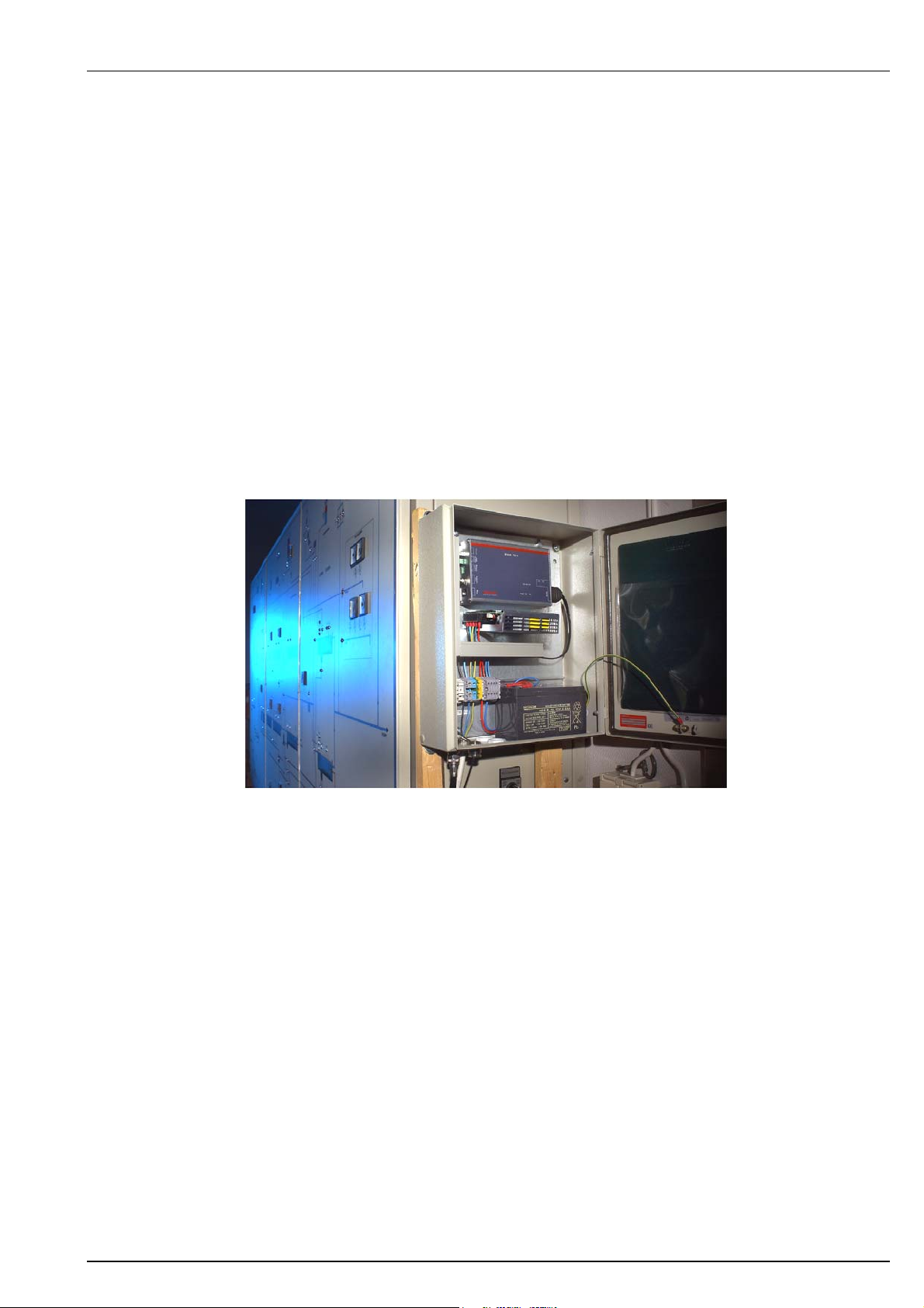
9.5 Cabinet Mounting _______________________________________________________________ 34
9.5.1 PDR 121 mounted in cabinet ____________________________________________________________34
10 Accessories____________________________________________________________ 35
11 Radio Networking _______________________________________________________ 36
11.1 Antennas __________________________________________________________________ 36
11.1.1 Antenna Gain _______________________________________________________________________36
11.1.2 Antenna Types ______________________________________________________________________ 37
11.1.3 Antenna Gain versus Radio Output Power _________________________________________________38
11.2 Fade Margin ________________________________________________________________ 39
11.3 Radio Link Calculations _______________________________________________________ 40
11.3.1 No Line of Sight Calculations ___________________________________________________________ 40
11.3.2 Line Of Sight Calculations______________________________________________________________43
12 Configuration __________________________________________________________ 45
12.1 Equipment _________________________________________________________________ 45
12.2 Getting Started ______________________________________________________________45
12.3 Configuration Menus Overview _________________________________________________ 46
iom_pdr121_04_r02.doc Rev 02 Page 2 (67)

RADIUS
12.4 Configuration Menus _________________________________________________________ 48
12.5 Network ___________________________________________________________________ 48
12.5.1 System ID __________________________________________________________________________48
12.5.2 Radio ID ___________________________________________________________________________48
12.5.3 RTU 01..20 – RTU 81..99 ______________________________________________________________49
12.5.4 Repeat Alternative Systems ____________________________________________________________50
12.5.5 View Network _______________________________________________________________________50
12.5.6 Clear Network _______________________________________________________________________50
12.6 Serial _____________________________________________________________________ 50
12.6.1 Protocol____________________________________________________________________________ 50
12.6.2 Bitrate _____________________________________________________________________________50
12.6.3 Parity______________________________________________________________________________ 50
12.6.4 Inter Character Timeout _______________________________________________________________50
12.6.5 Pre DCD ___________________________________________________________________________51
12.6.6 Post DCD __________________________________________________________________________51
12.7 Radio _____________________________________________________________________ 51
12.7.1 Collision Avoidance Delay _____________________________________________________________51
12.7.2 Collision Avoidance Delay Min __________________________________________________________51
12.7.3 Collision Avoidance Delay Max__________________________________________________________51
12.7.4 Bit Error Rate Test ___________________________________________________________________51
12.7.5 Communication Test __________________________________________________________________51
12.7.6 Radio Link Test ______________________________________________________________________51
12.7.7 Receiver Test _______________________________________________________________________ 52
12.7.8 Transmitter Test _____________________________________________________________________ 52
12.8 Advanced __________________________________________________________________ 52
12.8.1 Detected Radio Type _________________________________________________________________52
12.8.2 Rx Frequency _______________________________________________________________________52
12.8.3 Tx Frequency _______________________________________________________________________52
12.8.4 Split Tx Uplink _______________________________________________________________________53
12.8.5 Split Tx Uplink Frequency ______________________________________________________________53
12.8.6 Split Tx Uplink Id _____________________________________________________________________53
12.8.7 Radio Link Speed ____________________________________________________________________53
12.8.8 Tx Power Level ______________________________________________________________________53
12.8.9 Non-Intrusive Diagnostics ______________________________________________________________53
12.8.10 Realtime RSSI _____________________________________________________________________53
12.8.11 Extended Communication Test_________________________________________________________ 53
12.8.12 System Frequency Change ___________________________________________________________ 54
12.8.13 Remote Tx Power Level Change _______________________________________________________54
12.8.14 Radio VCO Lock Test ________________________________________________________________54
12.8.15 Terminal Bitrate_____________________________________________________________________54
12.9 List Configuration ____________________________________________________________ 55
12.10 Default Configuration _________________________________________________________ 55
Product Description
PDR 121
13 Configuration Examples__________________________________________________ 56
13.1 Network Layout _____________________________________________________________ 56
13.2 Network Menu Configurations – DNP3 ___________________________________________ 57
13.3 Network Menu Configurations – IEC870 / RP570 ___________________________________ 58
13.4 Network Menu Configurations – COMLI __________________________________________ 59
14 Radio Test Functions ____________________________________________________ 60
14.1 Bit Error Rate Test ___________________________________________________________ 60
14.2 Communication Test _________________________________________________________ 62
14.3 Radio Link Test _____________________________________________________________ 63
15 Trouble Shooting _______________________________________________________ 64
15.1 Trouble Shooting the PDR _____________________________________________________ 64
15.2 Support ____________________________________________________________________ 64
16 Education and user feedback _____________________________________________ 65
16.1 Product education ___________________________________________________________ 65
16.2 User feedback ______________________________________________________________ 65
iom_pdr121_04_r02.doc Rev 02 Page 3 (67)
RADIUS
Product Description
1 General
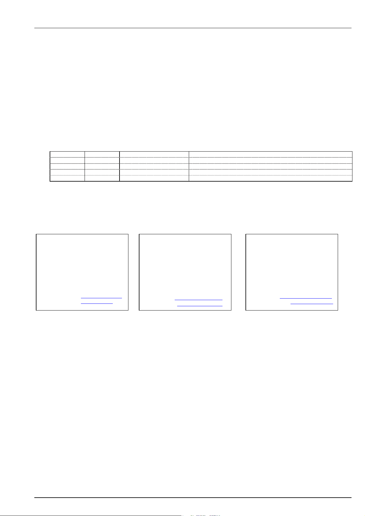
1.1 Document History
Created by: Arto Valtonen / Björn Rosenberg
Valid from: 2004-10-13
Latest Update: 2004-12-10
Approved: Anders Grahn
Template revision: 01, 001024
Revision Date Updated by Amendment
01 2004-10-13 Arto Valtonen First revision
02 2004-12-10 Arto Valtonen Second revision, added new configuration menus - ‘Advanced’
PDR 121
1.2 RADIUS Contact Information
RADIUS Sweden AB
Tennvägen 1
SE-371 50 KARLSKRONA
SWEDEN
Telefon: +46 455 30 90 00
Fax: +46 455 245 75
E-post: support@radius.se
Web: www.radius.se
RADIUS UK Ltd
Unit 4E
Bramhall Moor Technology Park
Pepper Road
Hazel Grove
SK7 5BW
ENGLAND
Phone: +44 161 484 2600
Fax: +44 161 484 2671
Email: support.uk@radius.se
Web: www.radius-uk.com
RADIUS US Inc.
10700 W. Venture Drive
Unit B
Franklin, WI 53132
USA
Phone: +1 (414) 427 7010
Fax: +1 (414) 427 7015
Email: support@radius-us.com
Web: www.radius-us.com
iom_pdr121_04_r02.doc Rev 02 Page 4 (67)

RADIUS
Product Description
2 Find Your Way in The Manual
Chapter 3 gives an introduction to Radius PDR 121 system and some application examples.
Chapter 4 contains technical specifications for the PDR 121.
Chapter 5 provides a Quick Start Guide for installation and configuration of the PDR 121
Chapter 6 contains a Glossary of Terms.
Chapter 7 describes the basic and extra features of the PDR 121.
Chapter 8 describes how the PDR 121 features can/should be used.
Chapter 9 contains installation guidelines, including the serial interface.
Chapter 10 contains information about radio network accesories provided by Radius.
Chapter 11 gives an introduction to general antenna and radio technique and calculations. This
chapter is inteded for those who want to learn more about those subjects.
Chaper 12 describes the PDR 121 configuration menus and how to set the different parameters.
Chapter 13 contains radio network configuration examples.
Chapter 14 describes the PDR 121 radio test functions.
Chapter 15 contains a list of trouble shooting check points.
PDR 121
iom_pdr121_04_r02.doc Rev 02 Page 5 (67)
RADIUS
Product Description
3 Introduction
Wireless communications remains the most cost effective solution for a significant amount of
modern applications. Advances in wireless technology allow data throughput and reliability to be
very high and, given the cost of direct cable or satellite infrastructure, price/performance benefits
remains far above other means of communication.
Modern wireless devices are much more than simple modems. They are sophisticated units,
designed to allow the user to create their own communication system with the minimum amount of
involvement.
The RADIUS PDR 121, Packet Data Radio 121, transceiver provides wide range data telemetry for
control and monitoring systems using the DNP3, IEC870 COMLI or RP570 protocol. The
transceiver is designed for point-to-multipoint operation environments including water, wastewater,
electric utilities, distribution automation, and gas field automation.
A PDR 121 system consists of one master and up to 99 slave radio units. Each slave radio can
operate as a repeater, stand-alone or with an RTU device connected. A message can be repeated
via up to six radios, 7 hops, to reach its destination. This gives a total coverage area of at least 200
km radius from the master.
The PDR 121 data radio is suitable for both polled and unsolicited systems. For unsolicited
systems, there is a Collision Avoidance functionality built-in to the radio that virtually eliminates inair collisions, vastly speeding up the communication throughput. It is also possible to carry out
Peer-To-Peer communication.
The radio communication is completely packet switched, which means all data is buffered
before/after transmitting/receiving on the radio. The radio transfer data rate is selectable,
4800/9600 or 9600/19200 bps, depending on desired channel bandwidth, 12.5 or 25 kHz.
The radio modem uses a Forward Error Correction technique, which corrects a large proportion of
transmission errors in case of noise bursts. This increases the radio sensitivity.
Routing of messages across the radio network is achieved by configuring the RTU addresses and
the Radio id’s in the PDR 121 Network menu. Messages are routed to the radio that is connected
to the destination address along the configured radio path. The radio network paths are easily
configured in the radio using a handheld terminal or a PC.
The control/monitoring device is connected to the PDR 121 via a standard RS232 serial interface.
The serial interface speed is adjustable between 600 and 19200 bps, with or without parity. The
transceiver only needs a three-wire connection, TxD, RxD and GND, but handshaking signals are
provided if required by the connected device.
The PDR 121 provides diagnostic features, remotely changeable parameters, built in survey and
test functionalities. All easily accessed via a hand terminal or a PC.
PDR 121
iom_pdr121_04_r02.doc Rev 02 Page 6 (67)

RADIUS
Product Description
3.1 Typical Application Areas
RADIUS has been a global player in the digital data wireless market for well over a decade, helping
a wide range of customers meeting their operational and financial targets. Working with SME’s up
to Blue Chip companies, RADIUS has provided products, systems and services to maximise the
benefit afforded by their wireless technology.
Our products are a result of the close relationship with our customers and partners and reflect the
current and future needs of the market.
Examples of why to go wireless:
• Replacing a cable in situations where installation of a cable is difficult, expensive or even
impossible.
• Replacing a dialled up link to reduce costs.
• Network provider independence.
Example application areas:
• Water/Wastewater
• Electric Distribution
• Gas Distribution
• Oil Distribution
• Wind Power
• Industrial Processes control
• Remote Traffic Control
• Railroad Communication Systems
• Remote PLC control
PDR 121
iom_pdr121_04_r02.doc Rev 02 Page 7 (67)
RADIUS
Product Description
3.1.1 Examples Of Typical Application Networks
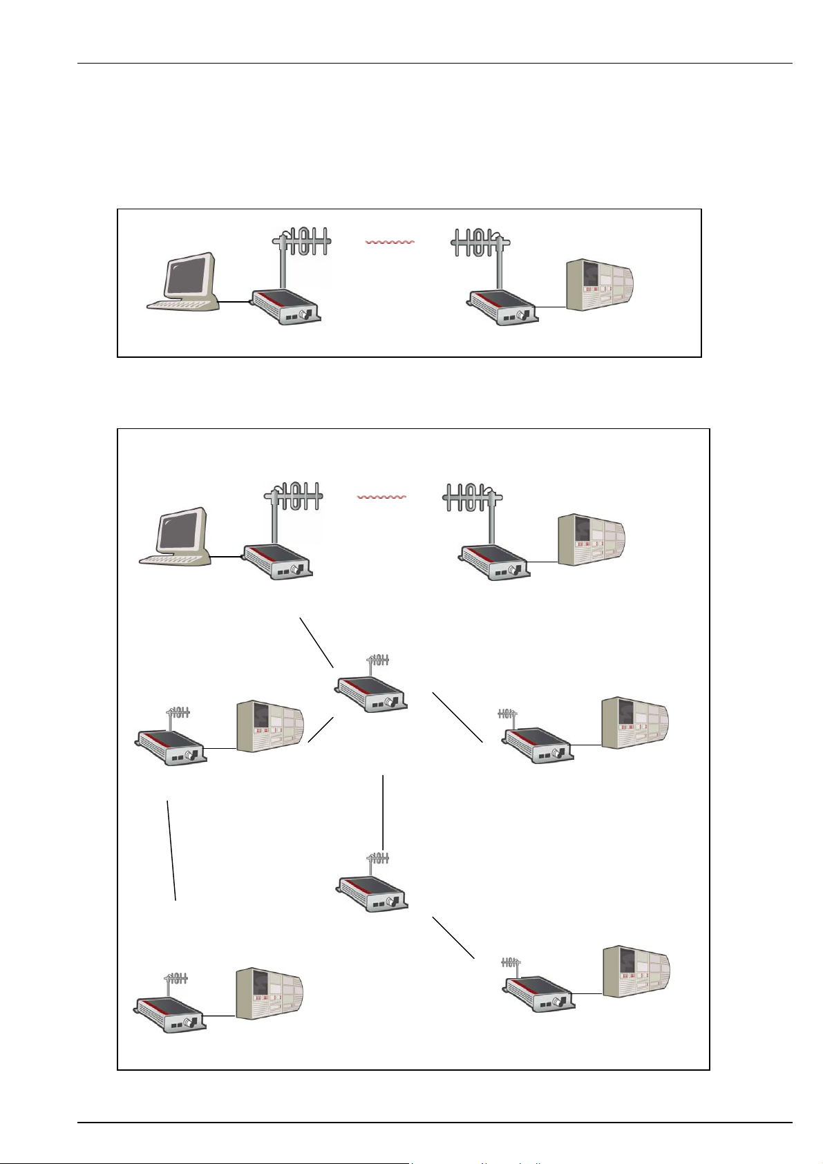
3.1.1.1 Point-to-Point
PDR 121
Control system
3.1.1.2 Point-to-Multipoint
Control system
PDR
PDR
PLC, RTU or other
devices
PLC, RTU or other
devices
PLC, RTU or other
devices
PLC, RTU or other
devices
PLC, RTU or other
devices
PLC, RTU or other
devices
iom_pdr121_04_r02.doc Rev 02 Page 8 (67)
RADIUS
Product Description
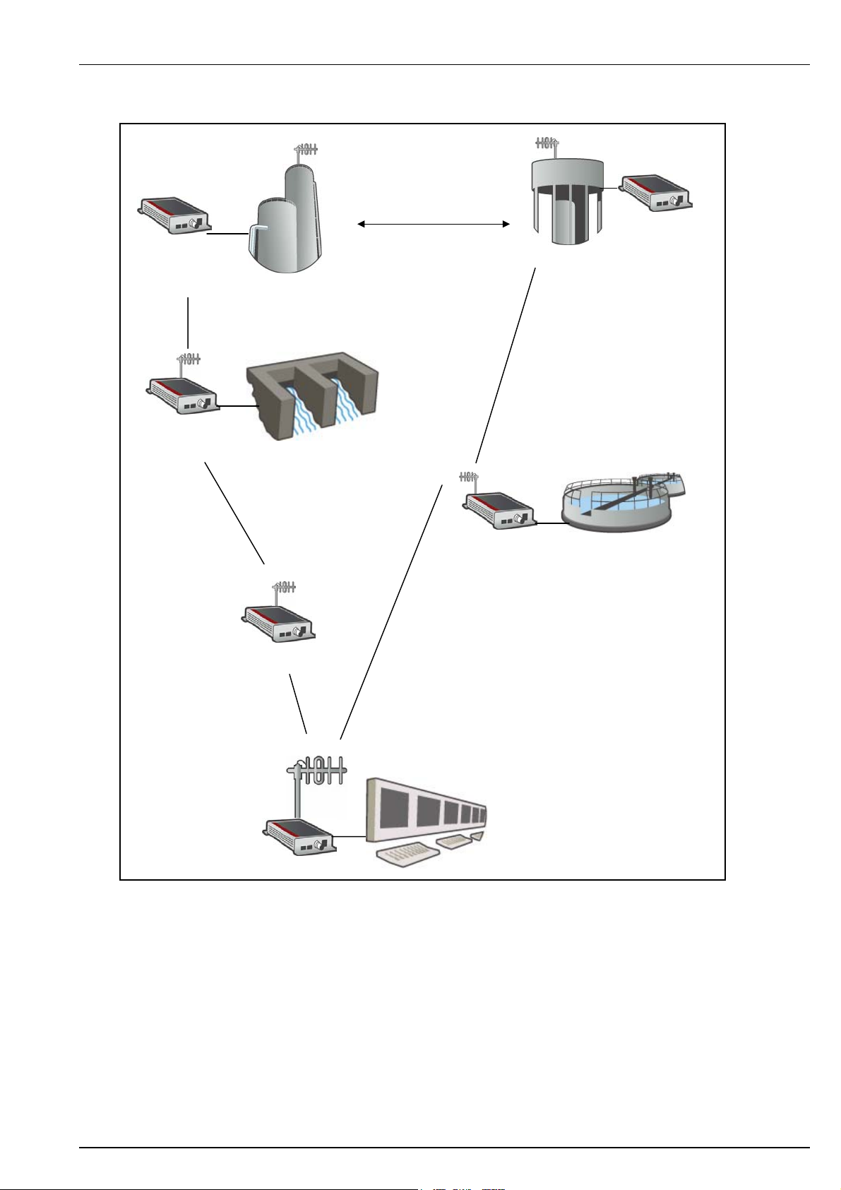
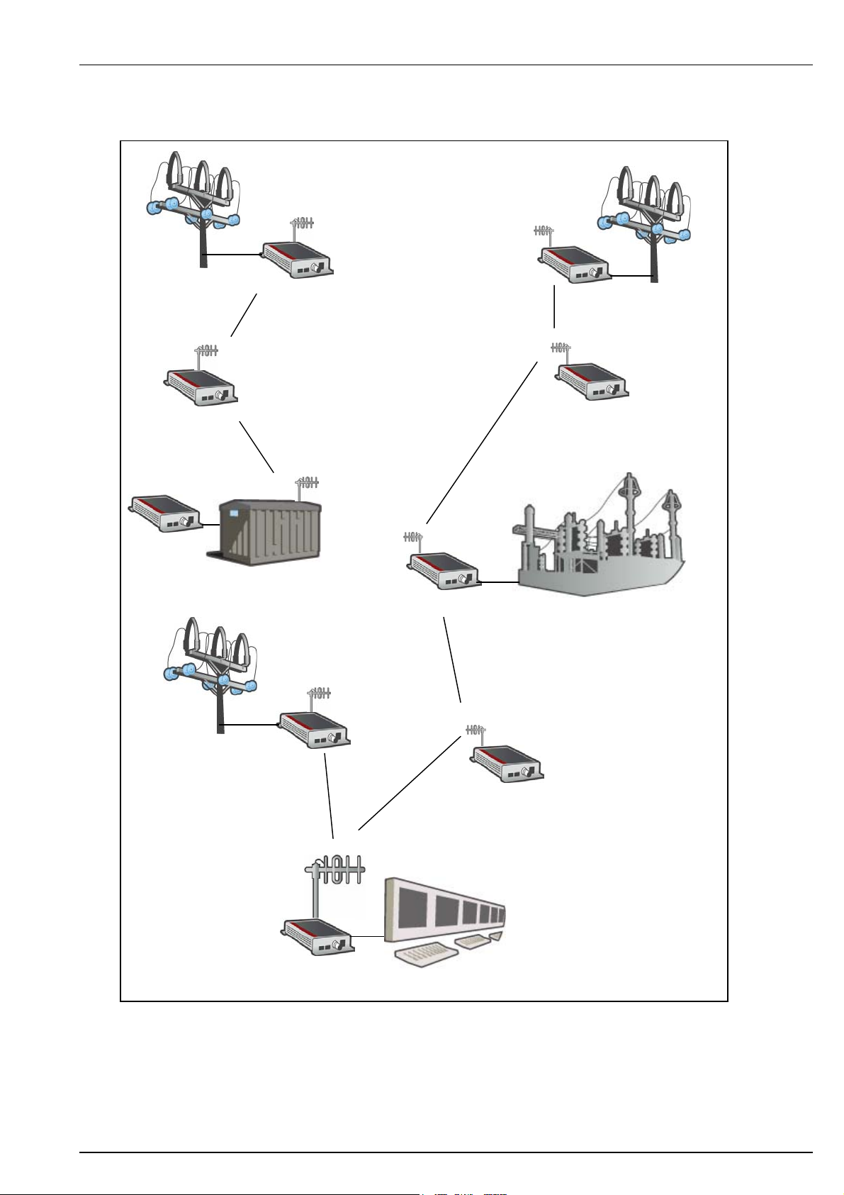
3.1.1.3 Water/Wastewater Network
PDR
Pump house
PDR
The example above shows two substations communicating Peer-To-Peer.
Water treatment plant
PDR 121
Peer-To-Peer
Reservoir
Waste water plant
Control system
iom_pdr121_04_r02.doc Rev 02 Page 9 (67)
RADIUS
Product Description
3.1.1.4 Electrical Distribution Network
Recloser
PDR 121
Metering points
Substation
Capacitor switch
Substation
Control system
iom_pdr121_04_r02.doc Rev 02 Page 10 (67)

RADIUS
Product Description
4 Technical Specifications
Radio Transceiver
Data Rates 4800…19200 bps
Frequency Range UHF 403..470 MHz. VHF 132…174 MHz. Other bands available on request.
Frequency Splits Various Tx/Rx frequency splits configurable
Operation modes Half Duplex, Simplex
Modulation 4 level FSK
Forward Error Correction Yes. With interleaving functionality.
Collision Avoidance Yes. User Configurable.
Repeating Multi-Repeating. Up to 6 repeaters on one link.
No of remote radios per master 99
Compliances ETSI 300220, ETSI 300113, MPT1411, FCC
Radio Transmitter
Tx Power 0.1…2.0 W. User Configurable.
Tx Power Accuracy +/- 1 dB
Radio Receiver
Sensitivity -107…-114 dBm @ BER 10
Spurious Emissions
Adjacent channel rejection >60dB
Serial Interface – RS232 Three wire, Rx/Tx/GND
Data Rates 600…19200 bps
Flow Control DCD/CTS flow control signals selectable.
Protocols DNP3, IEC870, RP570, COMLI
Power Supply
Operating voltage 10…16 VDC Nominal
Current Consumption Standby/Receive 165 mA. Transmit 1100 mA
Environmental
Temperature Operating Range -40°C to +60°C
Capsulation Class IP52
Physical Dimensions
Size 165x113x40 mm
Weight 600g
Housing Material Extruded Aluminium
Connectors
Main Power Supply 2 pole, Female, 3.81 mm split
Battery Supply 2-pole, Female, 5.08 mm split
Antenna BNC Female
Serial Port RS232 DB9 Female. Wired as DCE (modem).
Configuration Interface RJ12 Female
LED Indications Main PWR, Radio Rx, Radio Tx, RS232 Rx, RS232 Tx, Configuration Mode
Carrier Detect, System Detect
Configuration Interface
Configuration Software Standard Windows Terminal Program
Data Rate Selectable 1200 / 9600 / 57 600 bps. 57 600 Default.
-6.
. Depending on data rate and channel spacing.
PDR 121
iom_pdr121_04_r02.doc Rev 02 Page 11 (67)

RADIUS
Product Description
5 Quick Start Guide
PDR 121 provides many extra features, which are useful for different types of applications.
However, typical operation requires only a few of those. All feature configuration parameters have
default values to not interfere with normal operation, if not used.
PDR 121 is tuned at ordered frequency and Tx power. The user normally needs to configure only
the radio ID, operation mode and serial (RS232) settings, on each radio.
1. Install antenna(s) and antenna cable(s). See Radius Antenna Installation Manual.
2. Install the PDR 121 in to the RTU cabinet. / Install the PDR 121 cabinet. See chapter 9.
3. Connect the antenna cable, ground wire, RS232 cable and power supply to the PDR 221.
See chapter 9.
4. Configure the PDR 121 by using a hand held terminal or a PC. (Standard Windows
terminal software, 56700 N 8 1). The unit can also be pre-configured before installation.
Normally, the below listed parameters are the only ones needing configuration. See
chapter 12.
a. System ID (Menu 1. Network)
b. Radio ID (Menu 1. Network)
c. RTU address(es) (Menu 1. Network)
d. Radio path (if repeaters used) (Menu 1. Network)
e. RS232 (serial) parameters (Menu 2. Serial)
5. Perform Radio Link Test to all adjacent units. (Menu 3. Radio). See chapter 14.3.
6. Leave configuration mode by selecting E. – Exit in the main menu. (The yellow CM,
Configuration Mode, LED will turn off.)
7. The PDR 121 unit is now ready for operation.
PDR 121
iom_pdr121_04_r02.doc Rev 02 Page 12 (67)

RADIUS
Product Description
6 Glossary Of Terms
Some of the terms and abbreviations used in this product description may be unfamiliar if you are
new to digital radio systems. The following glossary explains these terms, which can be helpful in
understanding the operation of the PDR 121.
Bit – is the smallest unit of digital data, computational quantity that can take on one of two values,
such as false and true or 0 and 1.
bps – bits per second. The unit in which data transfer rate is measured across a communication
channel in serial transmissions. 9600 bps indicates that 9600 bits are transmitted in one second.
Byte – is often eight bits and the smallest addressable unit of storage.
Channel bandwidth – in addition to the direction of transmission, a channel is characterized by its
bandwidth. In general, the greater the bandwidth of the assigned channels, the higher the possible
speed of transmission.
Data telemetry – transmission of the values of measured variables using telecommunication
techniques
Decibel (dB) – is a unit of measurement of the strength of a signal
dBm – (Decibels below 1 Milliwatt) A measurement of power loss in decibels using 1 milliwatt as
the reference point.
DCE – Data Communication Equipment. The devices and connections of a communications
network that connect the communication circuit between the data source and destination (the Data
Terminal Equipment or DTE). A modem is the most common kind of DCE.
DTE – Data Terminal Equipment. A device which acts as the source and/or destination of data and
which controls the communication channel. DTE includes terminals, computers, protocol
converters, and multiplexers.
Fade Margin – The greatest tolerable reduction in average received signal strength that will be
anticipated under most conditions. This measurement provides an allowance for reduced signal
strength due to multi-path, slight antenna movement or changing atmospheric losses. A fade
margin of 10…20 dB is usually sufficient in most systems.
Flow Control – The collection of techniques used in serial communications to stop the sender from
sending data until the receiver can accept it. This may be either software flow control or hardware
flow control. The receiver typically has a fixed buffer size into which received data is written as
soon as it is received. When the amount of buffered data exceeds a "high water mark", the receiver
will signal to the transmitter to stop transmitting until the process reading the data has read
sufficient data from the buffer that it has reached its "low water mark", at which point the receiver
signals to the transmitter to resume transmission.
FSK Frequency Shift Keying – The use of frequency modulation to transmit digital data, i.e. two
different modulation frequencies are used to represent zero and one. More than two frequencies
can be used to increase transmission rates.
Master – is the unique application entity within the distributed application which directly or indirectly
controls the entire activity for this atomic action.
Multiple RTU addressing – several RTU’s share the same radio unit; each RTU has its own
address in the radio unit network list.
Slave – is a unit, which is under the control of another unit (Master).
Packet switched – Describing a system whereby messages are broken down into smaller units
called packets, which are then individually addressed and routed through the network.
.
PDR 121
iom_pdr121_04_r02.doc Rev 02 Page 13 (67)

RADIUS
Parity – A one-bit quantity indicating whether the number of 1’s in a word is even or odd.
Peer-to-Peer – Peer-to-Peer is a communications model in which each party has the same
capabilities and either party can initiate a communication session. Other models with which it might
be compared to, include the client/server model and the master/slave model. In some cases, peerto-peer communications is implemented by giving each communication node both server and client
capabilities.
Point-to-multipoint – is one-way or two-way communications from a central point to a number of
subsidiary points, and vice versa.
Poll – is a method to check the status of an input line, sensor, or memory location to see if a
particular external event has been registered. The communications control procedure by which a
master station or computer systematically invites tributary stations on a multipoint circuit to transmit
data.
Repeater – is a device that will repeat serial communications on to the predetermined destination.
Routing of messages – is the selection of a path or channel for sending a message.
RTU – is a Remote Terminal Unit that is physically remote from a main station or computer but can
gain access through communication channels.
RSSI (Received Signal Strength Indication) – a parameter returned from a transceiver that gives a
measure of the RF signal strength between the mobile station and base transceiver station, either
as an uplink or downlink measurement.
SCADA – (Supervisory Control and Data Acquisition) is a system used in industry to monitor and
control equipment status and provide logging facilities.
Transceiver – A terminal unit which can both transmit and receive information from a data
transmission circuit.
Unsolicited system – In an unsolicited response system, the RTU’s generate all reporting
messages required, without beein polled by the master. Typically, such messages report a change
of state or a fault, or simply pass data to the SCADA central host without being polled for the data.
Product Description
PDR 121
6.1 dBm to W Conversion Table
dBm Watts dBm Watts dBm Watts
0 1 mW 16 40 mW 32 1.6 W
1 1.3 mW 17 50 mW 33 2.0 W
2 1.6 mW 18 63 mW 34 2.5 W
3 2.0 mW 19 79 mW 35 3.2 W
4 2.5 mW 20 100 mW 36 4.0 W
5 3.2 mW 21 126 mW 37 5.0 W
6 4 mW 22 158 mW 38 6.3 W
7 5 mW 23 200 mW 39 8.0 W
8 6 mW 24 250 mW 40 10 W
9 8 mW 25 316 mW 41 13 W
10 10 mW 26 398 mW 42 16 W
11 13 mW 27 500 mW 43 20 W
12 16 mW 28 630 mW 44 25 W
13 20 mW 29 800 mW 45 32 W
14 25 mW 30 1.0 W 46 40 W
15 32 mW 31 1.3 W 47 50 W
iom_pdr121_04_r02.doc Rev 02 Page 14 (67)

RADIUS
Product Description
7 The PDR 121 Radio Transceiver Functionality
This chapter describes the PDR 121 radio functionality.
7.1 PDR 121 Operation Blocks
The figure below shows the basic building blocks of the PDR 121.
RS232
RS232 to RF
Serial data is received on the serial port. The MCU, (Micro Controller Unit), analyses the data and
frames the data and transfers it to the modulation unit. (The complete message is buffered in the
processor memory before being transmitted). The modem unit converts the received bit stream to a
4-level base-band signal for modulation of the radio transmitter.
RF to RS232
The modulation unit decodes the 4-level base-band signal and forwards the data to the MCU. The
MCU analyzes the message and prints it on to the serial port, (or re-transmits via the radio if the
message should be repeated).
PDR121
MCU
4 level FSK
Modulation
Radio
Transciever
PDR 121
RF
7.2 FEC - Forward Error Correction
On transmission, FEC bits are added to the transmitted data before being converted to a 4-level
signal. When receiving, the FEC information - and an FEC algorithm - is used to correct any
transmission errors. A large proportion of transmission errors can be corrected using the FEC.
7.3 CRC – Cyclic Redundancy Checksum
On transmission, a CRC byte(s) is added at the end of the data. The CRC byte is calculated based
on the data contents of the message. The receiver checks the CRC byte against the received data
and can detect any transmission errors. Corrupted messages are discarded.
Note! If the CRC is faulty, there is no non-acknowledge message (NACK) transmitted back from
the receiving radio. All re-transmissions have to be initiated by the connected device. Normally this
is trigged by a response timeout.
iom_pdr121_04_r02.doc Rev 02 Page 15 (67)
RADIUS
Product Description
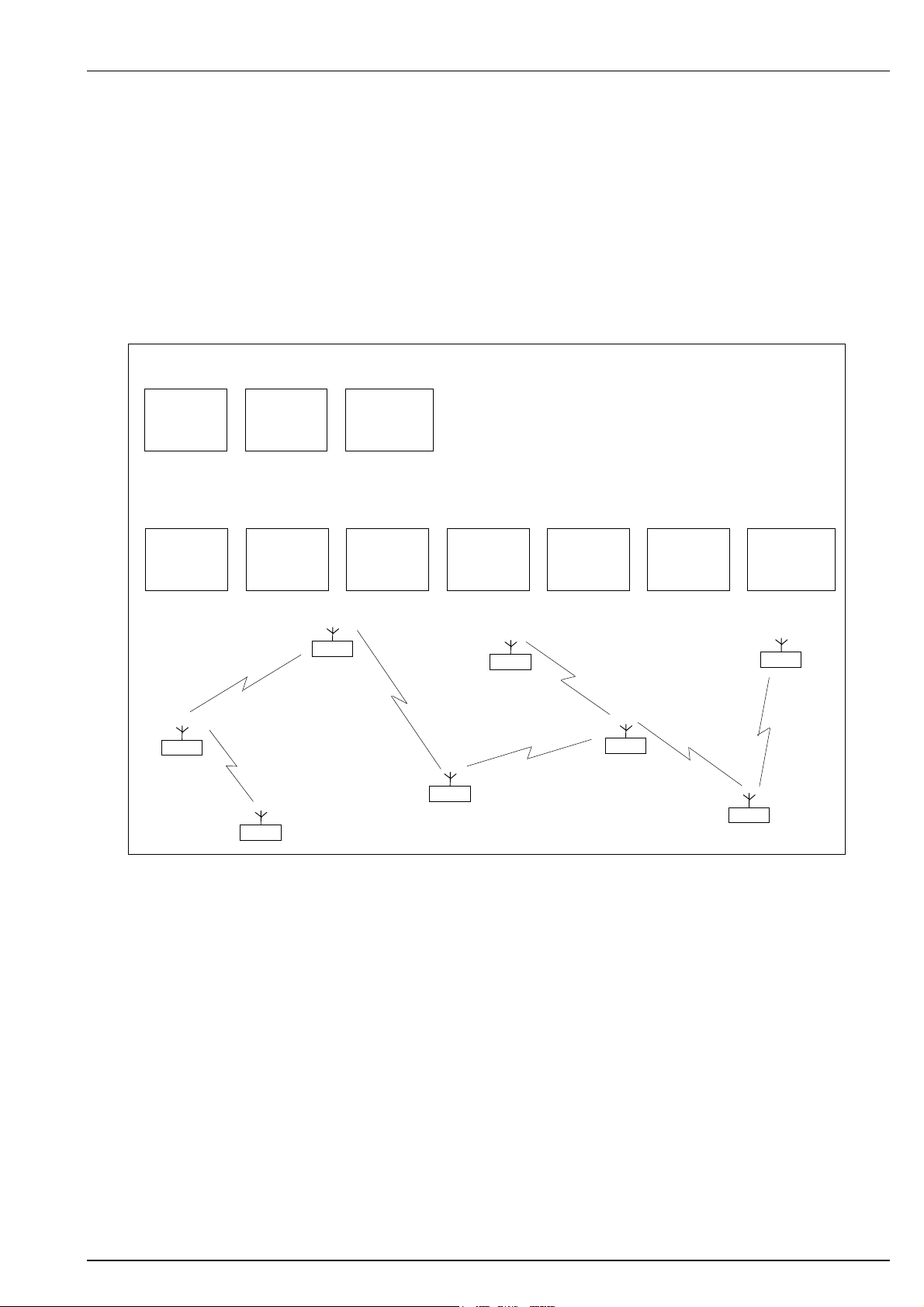
7.4 Communication
The PDR 121 can act as a master or a slave/repeater in the system. The routing information, RTU
addresses, radio identities and repeater paths, are configured in each radio unit.
When the connected control system transmits a telegram to the master, the master reads the
telegram address, i.e. the destination. The master compares the address to the configured network
routing table to check if there is a (slave) radio ID tied to the telegram address. If there is, the
master checks if the telegram shall be transmitted via any repeaters Finally the master radio
transmits the telegram to the slave via repeaters, if any. A reply back to the master is performed in
the same manner.
Example 1: Telegram from master to slave 7
The master
receives a
telegram from the
connected control
system
Example 2: Telegram from master to Slave 5 via the repeaters 1, 2, 3 and 4
The master
receives a
telegram from the
connected control
system
Master
The master
transmits the
telegram via radio
The master
transmits the
telegram via radio
Slave 7
Slave 7 receives the
telegram and
transmits it to the
control led system
(RTU or IED)
Repeater 1
receives and
transmits the
telegram via radio
Slave 1
Figure 1. Example of signalling procedure.
Repeater 2
receives and
transmits the
telegram via radio
Slave 2
Slave 6
Repeater 3
receives and
transmits the
telegram via radio
Slave 3
Repeater 4
receives and
transmits the
telegram via radio
PDR 121
Slave 7 receives the
telegram and
transmits it to the
connected device
Slave 5
Slave 4
iom_pdr121_04_r02.doc Rev 02 Page 16 (67)

RADIUS
Product Description
7.5 Radio Receiver Sensitivity
The receiver sensitivity depends on the frequency used, channel spacing, 12.5 / 25 KHz, and the
data speed, 4800, 9600 or 19200 bps. The receiver sensitivity is measured by attenuating a known
bit-pattern until bit error occurs. A standard way of presenting receiver sensitivity is for example:
-110dBm @ BER (Bit Error Rate) < 1x10
This means that there is less than 1 bit error out of 1 million bits when the signal strength at the
receiver is at –110 dBm.
It is important to know that this value in many cases can depend on the bit pattern used. RADIUS
uses a random bit pattern to determine receiver sensitivity, which includes all possible bit pattern
variations. This gives a very reliable, worst case, sensitivity measure.
Using gain antennas or increasing the output power of the transmitting radio can compensate for
the radio receiver sensitivity. Using gain antennas is often the most efficient solution.
It is important to note that a very sensitive radio cannot compensate for a poor antenna installation.
The sensitivity can be used in propagation studies for radio network planning.
-6
PDR 121
7.5.1 PDR 121 Receiver Sensitivity
Model
PDR 121-A VHF 132-150 12.5 4800 / 9600 -111 dBm / - 109 dBm
PDR 121-B VHF 132-150 25 9600 / 19200 -114 dBm / - 107 dBm
PDR 121-C VHF 150-174 12.5 4800 / 9600 -111 dBm / - 109 dBm
PDR 121-D VHF 150-174 25 9600 / 19200 -114 dBm / - 107 dBm
PDR 121-E UHF 435-450 12.5 4800 / 9600 -110 dBm / -107 dBm
PDR 121-F UHF 435-450 25 9600 / 19200 -110 dBm / -103 dBm
PDR 121-G UHF 450-470 12.5 4800 / 9600 -110 dBm / -107 dBm
PDR 121-H UHF 450-470 25 9600 / 19200 -110 dBm / -103 dBm
Frequency Range
[MHz]
Channel Bandwidth
[kHz]
Radio Data Speed
[bps]
Sensitivity
BER < 1x10⁻⁶
7.6 Radio Transmitter Power
The transmitting power ranges are from 0.1 to .2.0W for VHF transceivers and from 0.01 to 2.0W
for UHF transceivers. The transmitter power is tuned as ordered at the RADIUS factory, but can be
adjusted by the user via the software configuration menu - both locally and remotely. The output
power can be tuned in steps of 1dB between 0.1 and 2.0W, (20 dBm to 33dBm), for VHF and
between 0.5 and 2.0W, (27 to 33dBm), for UHF radios. Note! The UHF radios can be factory tuned
between 0.01 and 2.0W. (10dBm to 33dBm).
iom_pdr121_04_r02.doc Rev 02 Page 17 (67)
RADIUS
Product Description
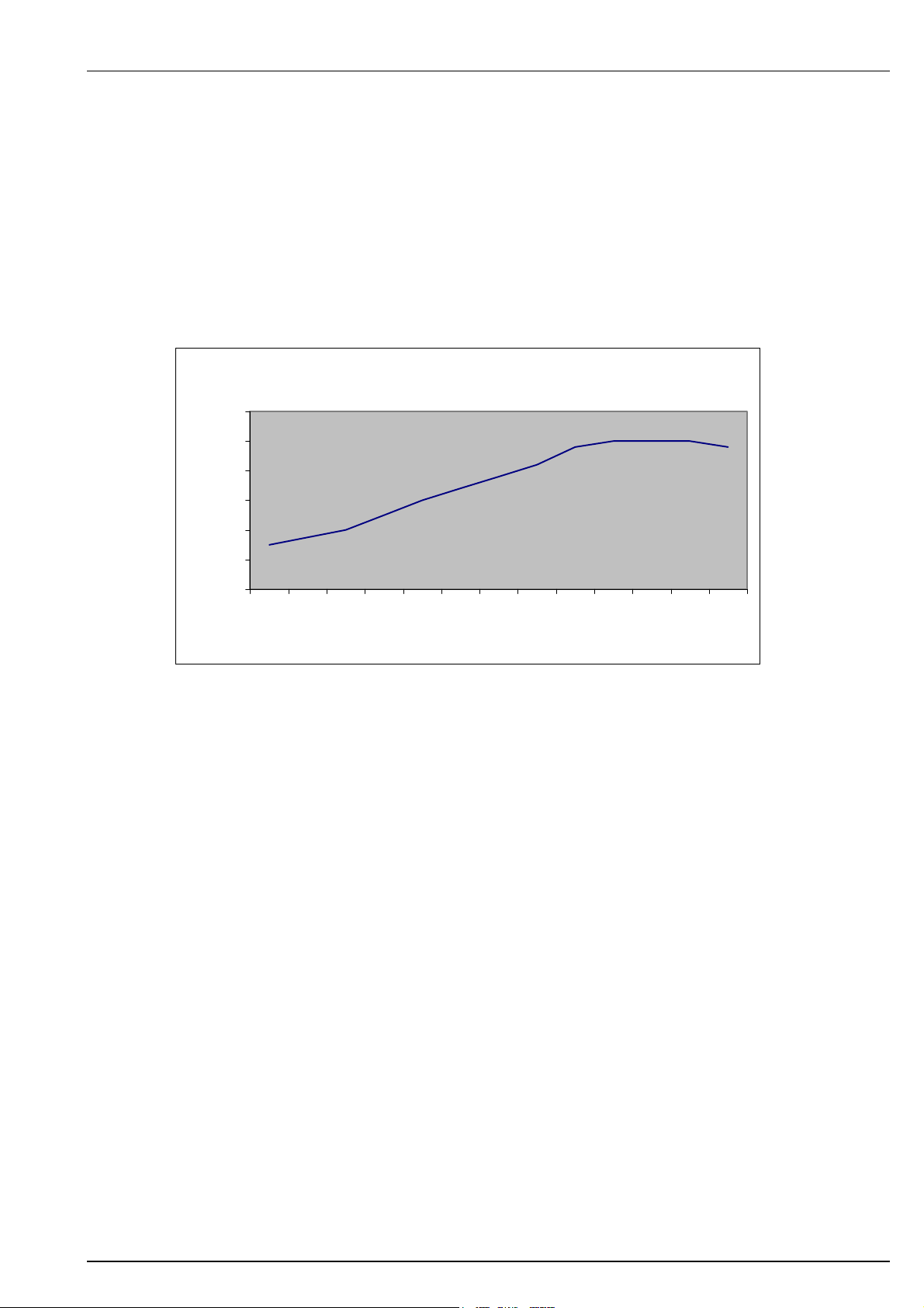
7.7 RSSI – Received Signal Strength Indication
The RSSI value can be used to determine the quality of a radio link. The RSSI values can be
retrieved by executing the Radio Link Test in the configuration menus, see 12.7.6.
The PDR 121 measures the RSSI value using an A/D converter. The received signal strength is
measured in volts and is translated to a dBm value.
The graph below shows a typical RSSI voltage value as a function of the signal level.
3
2,5
2
1,5
V
1
0,5
0
-130 -120 -110 -100 -90 -80 -70 -60 -50 -40 -30 -20 -10
RSSI
dBm
Figure 2. RSSI
PDR 121
iom_pdr121_04_r02.doc Rev 02 Page 18 (67)

RADIUS
Product Description
7.8 Differences between PDR 121 Models
All models of the PDR 121 are very similar in appearance and functionality. The only differences
are in frequency coverage, channel bandwidth and radio data speed. The table below summarizes
the available models and identifies the characteristics of each.
Model
PDR 121 132-150 12.5 4800/9600 305154-9
PDR 121 132-150 25 9600/19200 305155-8
PDR 121 150-174 12.5 4800/9600 305156-7
PDR 121 150-174 25 9600/19200 305157-6
PDR 121 403-422 12.5 4800/9600 305164-7
PDR 121 403-422 25 9600/19200 305165-6
PDR 121 435-450 12.5 4800/9600 305158-5
PDR 121 435-450 25 9600/19200 305159-4
PDR 121 450-470 12.5 4800/9600 305160-1
PDR 121 450-470 25 9600/19200 305161-0
Other frequency ranges are available on request. Contact RADIUS for further information.
Frequency Range
[MHz]
Channel Bandwidth
[kHz]
Radio Data Speed
[bps]
Article Number
PDR 121
iom_pdr121_04_r02.doc Rev 02 Page 19 (67)
RADIUS
A
Product Description
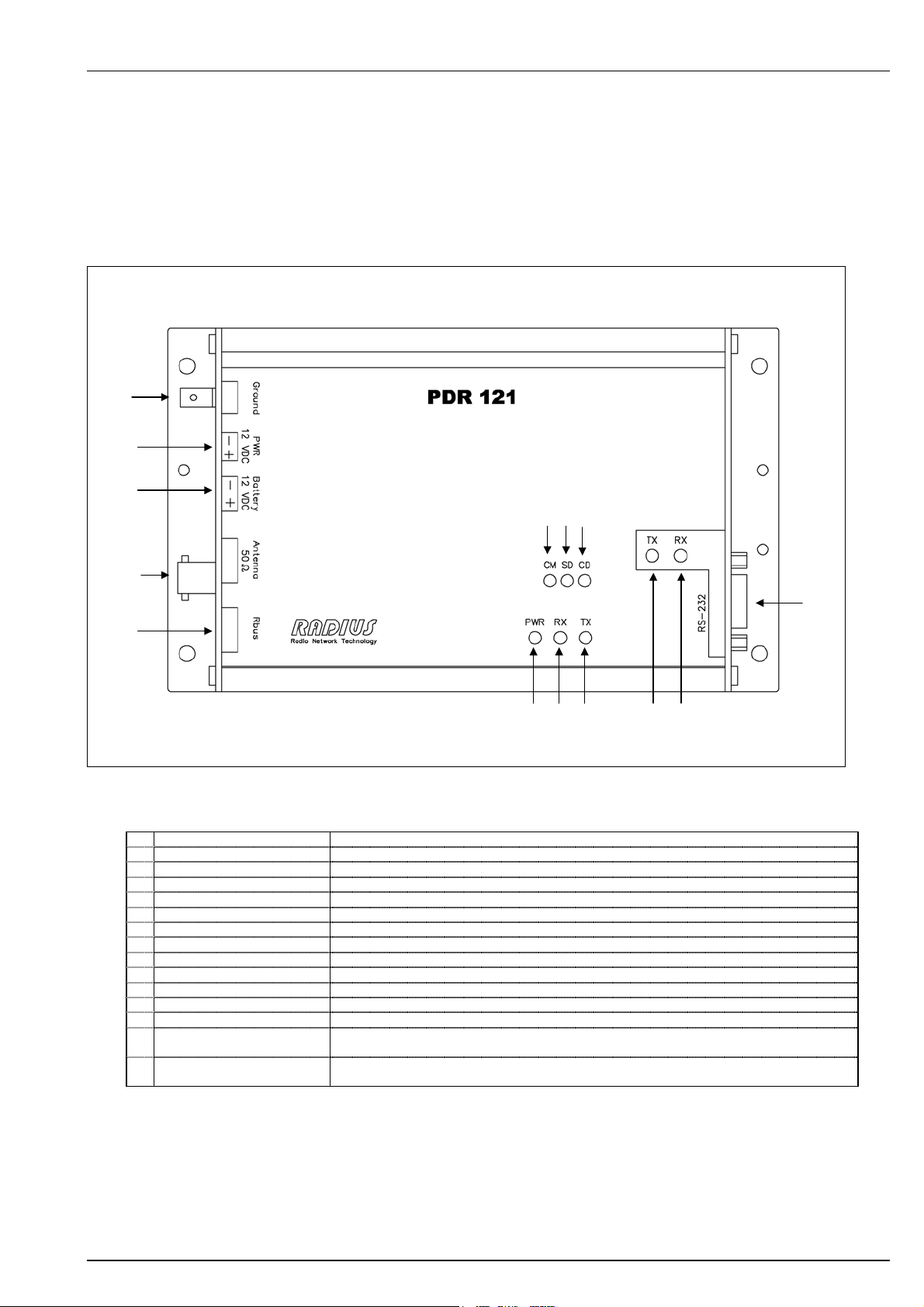
8 Operating the PDR 121
8.1 LED Indicators and Connectors
PDR 121
B
C
D
LMN
K
E
Figure 3. Packet Data Radio 121.
GF
H
I
Name Description
A Earth/ground connection For connection to the system’s earth/ground (Internally connected to PWR negative (-) pole.)
B Voltage connection For connection of 12VDC
C Battery connection For connection of a backup-battery, 12VDC. Note! No battery charging. See 9.3.
D Coaxial connection For connection of the antenna cable
E Rbus connection For connection of the Programming interface ProgInt
F PWR LED (Green) Is lit when the PDR has power supply
G RX LED (Yellow) When lit, the PDR receives data from another radio unit in the system
H TX LED (Red) When lit, the PDR transmits data via radio
I RS232 Tx LED (Red) When lit, the PDR transmits serial data to connected device
J RS232 Rx LED (Green) When lit, the PDR receives serial data from connected device
K RS-232 connection For connection of the serial cable. 9-pole D-sub plug
L Configuration Mode (Yellow) Lit when the PDR 121 is in configuration mode
M System Detect (Yellow) Lit (flashed) if the radio detects a PDR transmission from another system. I.e. not valid system
N Carrier Detect (Yellow) Lit (flashed) when a carrier is detected. Can be used to detect interfering signals. (If the Rx
id.
LED is not lit simultaneously).
Note! The PDR 121 does not charge batteries via the battery connection jack. See chapter 9.3.
iom_pdr121_04_r02.doc Rev 02 Page 20 (67)

RADIUS
Product Description
8.2 Peer-To-Peer
The PDR 121 offers the feature of peer-to-peer communication. Any PDR 121 unit can
communicate with another, independently from a master unit.
Peer-To-Peer communication is achieved by entering the Peer destination address in the network
configuration menu. See chapter 12.5.
Note! The control system and the protocol used must support Peer-To Peer communication. Check
this with your control system supplier or contact RADIUS.
8.3 Collision Avoidance
Collision Avoidance is used in systems operating with unsolicited messaging / report by exception,
meaning that it is a not strictly polled, (request/reply), system. If events occur simultaneously at
several RTU’s in an unsolicited system, there is a risk that several radios start transmitting
simultaneously. The radio messages will then be corrupted due to collisions.
Unsolicited response / Report by Exception messages are commonly used by equipment using the
DNP3 protocol.
The Collision Avoidance functionality in the PDR 121 is used to minimize the risk of collisions at
simultaneous and cascading events on a RTU network.
The basic strategy is that the PDR 121 always listens to the radio channel. If it detects a
transmission from another radio, it will not start a transmission until the ongoing transmission is
finished. Though, it is still possible that two, or more, radios listens to the channel, consider it free
and start transmitting simultaneously. Configuring a random back-off delay time, called Collision
Avoidance Delay, solves this issue.
If the Collision Avoidance Delay function is activated, the radio will wait a random time after
receiving a serial message from connected device before transmitting a radio message. The radio
listens to the radio channel during the back-off time. This makes it possible to detect another
transmission initiated by another radio, which started the transmission after a shorter back-off time.
Collision is avoided. The radio that backed-off will re-initiate the random delay time when the
channel is free again.
The Collision Avoidance Delay is configured to a Min and Max value. See configuration in chapter
12.7.
Collision Avoidance Min is the time in seconds the radio always waits from when the radio
channel is free until it starts a transmission. Note that the Min time is not random. This value can be
set to zero.
Collision Avoidance Max is the maximum limit for the random time.
The random time is calculated from the difference between CA Min and CA Max.
PDR 121
iom_pdr121_04_r02.doc Rev 02 Page 21 (67)
 Loading...