

Radio Thermostat of America CT200R1 Users Guide
VIVINT ELEMENT THERMOSTAT
USER GUIDE
COMMUNICATING TOUCH SCREEN THERMOSTAT

CT200 INSTALLATION GUIDE
Table Of Contents
Getting Started. . . . . . . . . . . . . . . . . . 3
Interior View 5
Installation Location 6
Wiring . . . . . . . . . . . . . . . . . . . . . . . 8
Mounting Plate 9
Prepare Wires 10
Connecting Wires 11
Power Supply 12
Setup . . . . . . . . . . . . . . . . . . . . . . .14
Connecting to a Z-Wave network 15
Z-Wave and Thermostat Programs 16
Select HVAC & Heat Types 18
Test Installation 20
Wiring Diagrams . . . . . . . . . . . . . . . .22
Detailed Wire Diagram 23
Step By Step Wiring Diagrams 24
Wire Reference Table 28
2

Getting Started
Radio Thermostat
3
Vivint Element CT200 Installation Guide
Getting Started
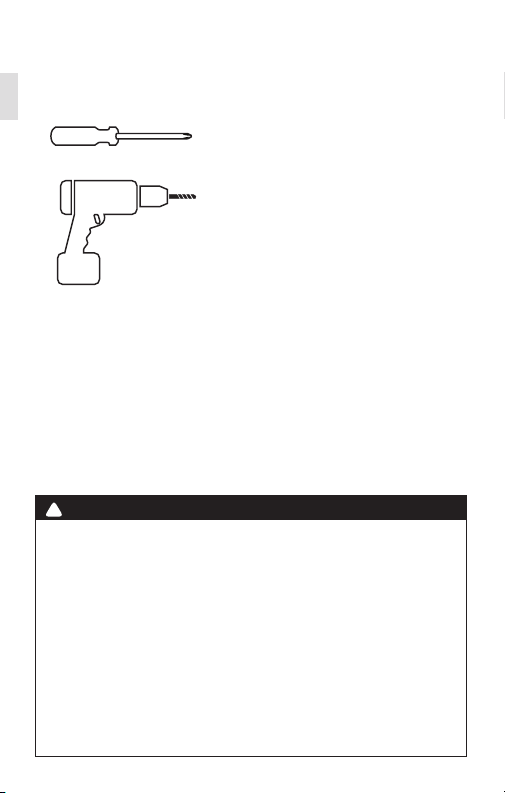
Tools Needed
Small Phillips screwdriver
Drill with ¼" bit (6 mm)
CAUTION
!
To avoid electrical shock and to prevent damage to the furnace, air conditioner, and thermostat, disconnect the power supply before installing or
servicing the thermostat or any part of the system. This can be done at the
circuit breaker for both the furnance and air conditioner.
• Do not reconnect electricity until work is complete.
• Do not short (jumper) across electric terminals at the control on the
furnace or air conditioner to test the system. This can damage the
thermostat.
• Your thermostat is a precise instrument. Handle it with care.
• All wiring must conform to local codes and ordinances.
• This thermostat is designed for use with 4AA alkaline batteries and/or 24-
volt AC C wire (or a 12- 24 AC or DC source) or millivolt gas systems. Each
thermostat relay load should be limited to 1.0 amp; higher amperage can
cause damage to the thermostat.
4
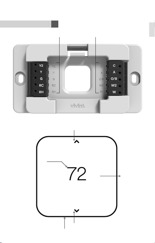
Interior View
Unit Back and Mounting Plate
Vivint Element CT200 Installation Guide
Getting Started
Wire terminals
Unit Front
Screen
Up Button
Down Button
Bottom Edge Light
Side
Button
5
Vivint Element CT200 Installation Guide
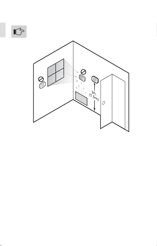
Installation Location
To avoid having to move your wiring to a new location,
mount the thermostat in place of the old thermostat.
• Install the thermostat on an inside wall of an often-used room, about
5 ft. (1.5m) above the oor.
• Do not install where there are unusual heating conditions, such as:
in direct sunlight; near a lamp, radio, television, radiator register,
replace; near hot water pipes in the wall; or near a stove on the
other side of a wall.
• Do not locate in unusual cooling conditions, such as: on a wall
separating an unheated room; or in a draft from a stairwell, door, or
window.
• Do not locate in a damp area. This can lead to corrosion that will
shorten the thermostat’s life.
• Do not locate where air circulation is poor, such as: a corner, an
alcove, or behind an open door.
• Do not install the thermostat until all construction and painting is
complete.
• This thermostat does not require leveling.
Getting Started
6

Wiring
Radio Thermostat
7
Vivint Element CT200 Installation Guide
C
W
RH
G
Y
Preperation
!
CAUTION
• Read instructions carefully before removing any wiring from an existing
thermostat.
• Label all wires before disconnecting them form the existing thermostat.
Wiring
1. Switch o electricity to the heating and cooling systems. This can
be done at the circuit breaker.
2. Remove the cover from the existing thermostat. Check for locking
screws on the side or front that must be loosened rst.
3. Attach provided labels to each wire for identication. Refer to the
lettered terminal where the wires attach; do not use the color of
the wires.
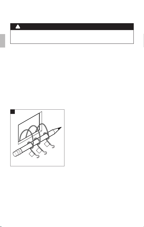
4. Disconnect wires from the existing thermostat, and wind them
around a pencil to keep them from falling back inside the wall.
5. Loosen all mounting screws on the old thermostat and remove it
from the wall.
4
W
G
C
8
Vivint Element CT200 Installation Guide
C
W
RH
G
Y
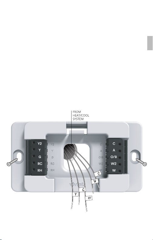
Attaching the Mounting Plate to the wall
Wiring
1. Carefully pull the labeled wires through the center hole in the
mounting plate.
2. Position thermostat for best appearance to cover the hole in the
wall.
3. Mark rst and drill a ¼ in. (6mm) hole at each screw location.
4. If you are mounting the Thermostat to sheet rock or if you are
using the old mounting holes, use the plastic anchors provided.
5. Attach the Thermostat to the wall with the screws provided.
9
Prepare Wires
C
W
RH
G
Y
Vivint Element CT200 Installation Guide
Wiring
Make sure your wires are labeled. If necessary, nd the “other
end” connection for each wire on your heating or air conditioning
equipment and note the label there.
1. Fan out wires so that they are aligned with their terminals.
2. Do not bunch wires in front of the mounting plate. Feed any slack
back into the wall.
If you have both RH
and RC connections,
you must set the RC/
RH Switch to OPEN. If you do
not have both connections,
set the switch to CLOSED.
Follow these guidelines for safe and secure wire connections:
!
CAUTION
Do not allow wires to touch
each other or other parts on
the thermostat.
• Use at least 2.6 in. of wire for each of your connections to the
Thermostat.
• If you do not have enough wire, splice additional wire to allow
enough slack.
• Terminals accept wires from 16-22 awg.
• Remove 1/8 in. insulation from the tip of each wire.
• Take care not to damage the labels for each wire.
10
Connecting Your Wires
C
W
RH
G
Y
Vivint Element CT200 Installation Guide
Wiring
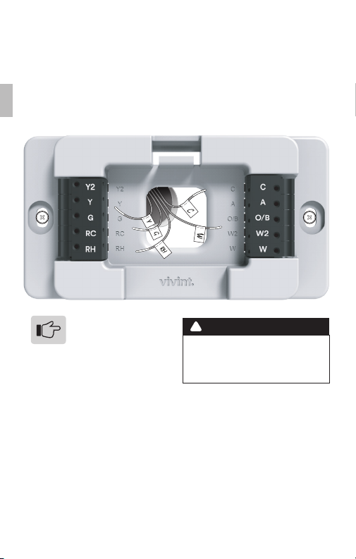
Reference the Detailed Wire Diagram on page 23 to identify your
wiring diagram and set-up information. If necessary, contact
customer support for help.
1. Connect a labeled wire only to a matching lettered terminal.
2. Press the lever next to the terminal letter, then insert the wire in
the terminal well.
3. Make sure to insert the wire into the terminal well as far as it will
go, then release the lever. The wire should be secure and not pull
free easily.
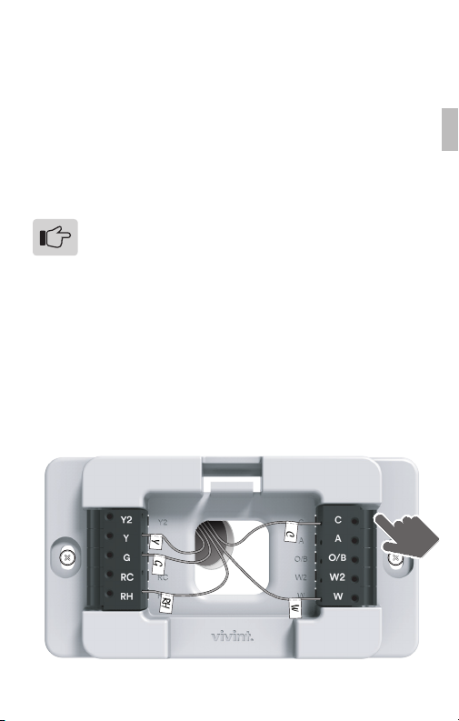
The Thermostat can be externally powered with a power
source rated from 12V to 24V, AC or DC, at 100ma or
greater. If used, connect to the C and RH terminals (no
polarity).
The 24VAC “C” wire is the other side of the 24VAC heating
transformer and can be found where the other thermostat
wires connect at the wall or at the furnace. Do not use the
common or ground side of the line voltage.
The Thermostat runs on 4 AA alkaline batteries, the C wire
(if available), or both batteries and the C-wire. If you do not
have a C wire, you can run a new wire from the HVAC or
use a standard 12-24V [AC or DC] wall transformer.
The C-wire is optional but preferred for all installations.
Example of 5 Wire
Heat/Cool System
11

Vivint Element CT200 Installation Guide
Power Supply
While the thermostat can run without batteries on C-wire power,
you should install batteries as well to provide power to the unit
during outages. See the Thermostat Battery Cautions.
1. Install four (4) AA alkaline batteries following the marked polarity
in the battery compartments. Insert the battery negative end rst
against the spring, then push the positive end in.
2. With all the wires connected and the unit attached to the wall, it
is time to turn the AC power back on. Reconnect the power at the
breaker you used to switch it o. The Thermostat will power-up in
the OFF mode.
3. Your Thermostat is not yet congured to operate your HVAC
system. You must now connect your thermostat to a Z-Wave
Network and congure the HVAC and Heat Source settings.
Battery Installation
Wiring
12
Vivint Element CT200 Installation Guide
Wiring
!
THERMOSTAT BATTERY CAUTIONS
• Always use new Alkaline batteries.
• Do not use rechargeable batteries of any type. They will not operate the
thermostat properly and may lead to damage.
• Do not mix old and new batteries.
• Do not mix battery types, for example Lithium with Alkaline.
• Do not dispose of batteries in re. Batteries may explode or leak.
• Always replace the batteries as soon as the “Low Batt” warning ashes. The
thermostat is a battery-powered device; you should replace the batteries
before they run out, as failure to replace batteries can result in excessive
heating or cooling of your house.
• Always replace the batteries once a year, even if the “Low Batt” indicator
does not ash. Replacing the batteries also helps to prevent leakage that
can corrode and damage the thermostat.
• If you are leaving your home for a month or more, you should replace the
batteries as a precaution against battery failure in your absence.
• Failing to replace the batteries when necessary could cause the thermo-
stat to lose power or malfunction. If the thermostat loses power, then the
thermostat will not control the temperature, which could result in your HVAC
system not functioning as you intended and lead to possible damage from
excessive heating or cooling.
• If the thermostat batteries fail with the heat OFF, this can result in NO HEAT
and possible frozen or broken pipes and water damage.
• If the thermostat batteries fail with the cool OFF, this can result in NO COOL
and could cause possible damage or excessive temperatures.
13

Setup
Vivint Element CT200 User Guide
14
 Loading...