

Page 1
CT102 USER GUIDE
COMMUNICATING TOUCH SCREEN THERMOSTAT
PM
RADIO
1
LINK
TARGETTEMP
DAY
AUTO
F
Su Mo Tu We Th Fr Sa
HEAT
Page 2

CT102 INSTALLATION GUIDE
Table Of Contents
Getting Started #
Interior View
Installation Location #
Wiring #
Prepare Wires #
Connecting Wires #
Mounting #
Setup #
Select HVAC & Heat Types #
Power Supply #
HVAC Setup #
Test Installation #
Wiring Diagrams #
Detailed Wire Diagram #
Step By Step Wiring Diagrams
Wire Reference Table #
2
Page 3

Getting Started
Radio Thermostat
3
Page 4
Installation Guide CT102
Getting Started
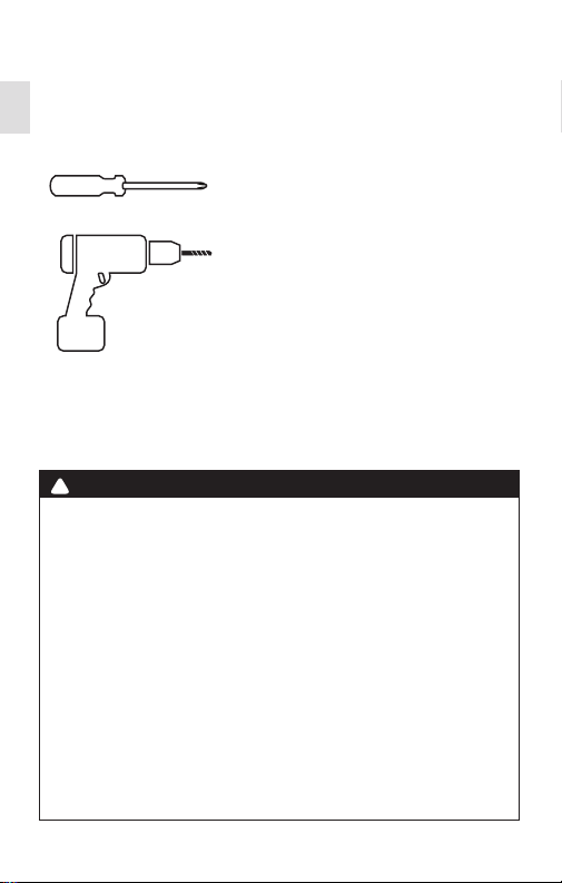
Tools Needed
Small Phillips screwdriver
Drill with 3/16- in.(4.8mm) bit
!
CAUTION
• To avoid electrical shock and to prevent damage to the
furnace, air conditioner, and thermostat, disconnect the power
supply before installing or servicing the thermostat or any part
of the system. This can be done at the circuit breaker.
• Do not reconnect electricity until work is complete.
• Do not short (jumper) across electric terminals at the control
on the furnace or air conditioner to test the system. This can
damage the thermostat.
• Your thermostat is a precise instrument. Handle it with care.
• All wiring must conform to local codes and ordinances.
• This thermostat is designed for use with 4AA alkaline batteries
and/or 24- volt AC C wire (or a 12- 24 AC or DC source) and
millivolt gas systems. Each thermostat relay load should be
limited to 1.0 amp; higher amperage can cause damage to the
thermostat.
4
Page 5
WIRE
TOUCH
SCREEN
STATUS
INDICATOR
RESET
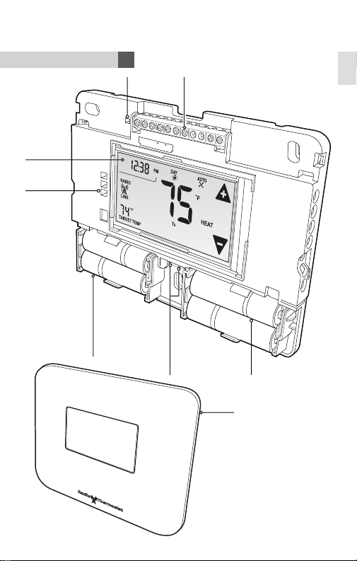
Interior View
Installation Guide CT102
Getting Started
TERMINALS
C
B
O
W
W2
Y
Y2
RH
RC
G
A
UX
1
2
A
BATTERIES
HVAC
SELECTION
SWITCHES
BATTERIES
COVER
5
Page 6
Installation Guide CT102
Getting Started
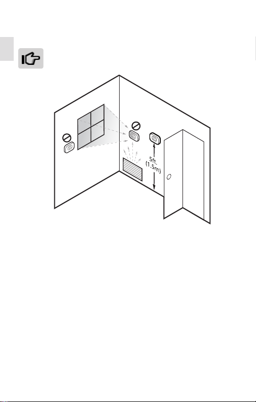
Installation Location
To avoid having to move your wiring to a new location,
mount the CT102 in place of the old thermostat.
• Install the thermostat on an inside wall of an often-used room, about
5 ft. (1.5m) above the oor.
• Do not install where there are unusual heating conditions, such as:
in direct sunlight; near a lamp, radio, television, radiator register,
replace; near hot water pipes in the wall; or near a stove on the
other side of a wall.
• Do not locate in unusual cooling conditions, such as: on a wall
separating an unheated room; or in a draft from a stairwell, door, or
window.
• Do not locate in a damp area. This can lead to corrosion that will
shorten the thermostat’s life.
• Do not locate where air circulation is poor, such as: a corner, an
alcove, or behind an open door.
• Do not install the CT102 until all construction and painting is
complete.
• This thermostat does not require leveling.
6
Page 7
Installation Guide CT102
Getting Started
!
CAUTION
• Read instructions carefully before removing any wiring from an
existing thermostat.
• Label all wires before disconnecting them form the existing
thermostat.
1. Switch o electricity to the heating and cooling systems. This can
be done at the circuit breaker.
2. Remove the cover from the existing thermostat. Check for locking
screws on the side or front that must be loosened rst.
3. Attach provided labels to each wire for identication. Refer to the
lettered terminal where the wires attach; do not use the color of
the wires.
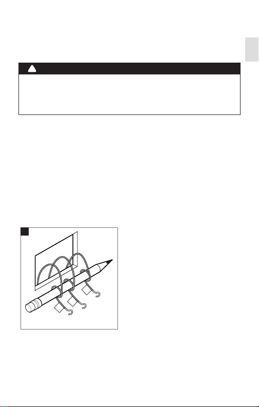
4. Disconnect wires from the existing thermostat, and wind them
around a pencil to keep them from falling back inside the wall.
5. Loosen all mounting screws on the old thermostat and remove it
from the wall.
4
W
G
C
7
Page 8
Installation Guide CT102
Wiring
Prepare Wires
Make sure your wires are labeled. If necessary, nd the “other
end” connection for each wire on your heating or air conditioning
equipment and note the label there.
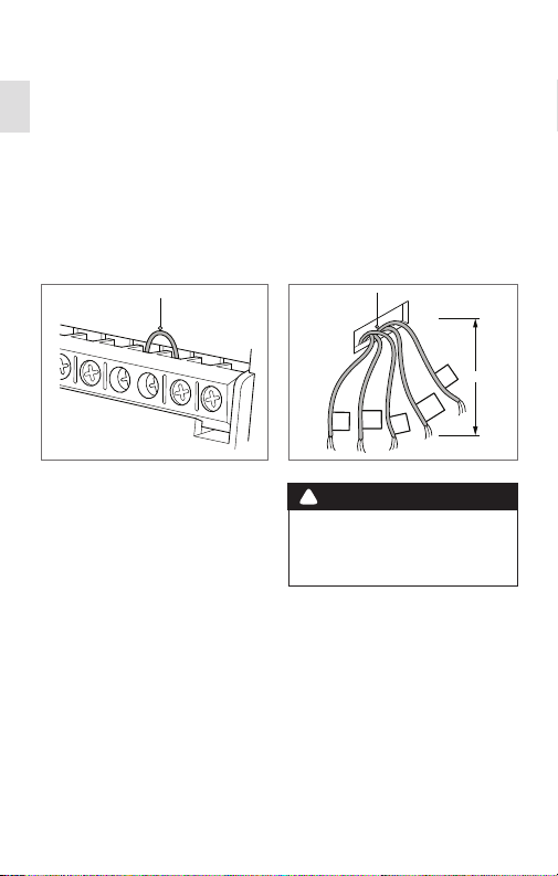
1. Fan out wires so that they are aligned with their terminals.
2. Position wires behind the CT102 and over the terminal area.
3. Do not bunch wires behind the CT102. Feed any slack back into
the wall opening.
JUMPER WIRE
Y
Y2
RH
RC
G
A
If you have both RH and
RC connections you must
remove the jumper wire
between these two terminals.
FROM HVAC
SYSTEM
RH
W
C
Y
!
CAUTION
Do not allow wires to touch
each other or other parts on
the thermostat.
Follow these guidelines for safe and secure wire connections:
• Use at least 2.6 in. of wire for each of your connections to the
CT102.
• If you do not have enough wire, splice additional wire to allow
enough slack.
• Terminals accept wires from 16-22 awg.
• Remove 1/8 in. insulation from the tip of each wire.
• Take care not to damage the labels for each wire.
8
2.6”
G
Page 9
Installation Guide CT102
Wiring
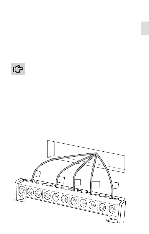
Connecting Your Wires
Reference the Wire Diagram on page # to identify your wiring
diagram and set-up information. If necessary, contact customer
support for help.
1. Connect a labeled wire only to a matching lettered terminal.
2. Insert the wire in the terminal well and tighten the screw securely.
The CT102 can be externally powered with a power source
rated from 12V to 24V, AC or DC, at 300ma or greater. If
used, connect to the C and RH terminals (no polarity).
The 24VAC “C” wire is the other side of the 24VAC heating
transformer and can be found where the other thermostat
wires connect at the wall or at the furnace. Do not use the
common or ground side of the line voltage.
The CT102 runs on 4 AA alkaline batteries, the C wire (if
available), or both batteries and the C-wire. If you do not
have a C wire, you can run a new wire from the HVAC or
use a standard 12-24V [AC or DC] wall transformer.
The C-wire is optional but preferred for all installations.
From HVAC System
C
W
C
B
O
W
W2
Y
RH
Y
Y2
RH
RC
G
G
A
9
Page 10
Installation Guide CT102
Wiring
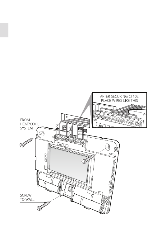
Mount the CT102 to the Wall
1. Hold the CT102 against the wall, with the wires coming over the
top; above terminal block.
2. Position CT102 for best appearance, cover the hole in the wall.
3. Mark rst and drill a 3/16-in.(4.8mm) hole at each screw location.
4. If you are mounting the CT102 to sheet rock or if you are using the
old mounting holes, use the plastic anchors provided.
5. Attach the CT102 to the wall with the screws provided.
10
Page 11

Setup
Radio Thermostat
11
Page 12
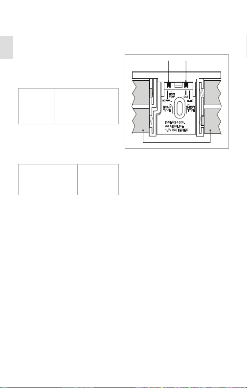
Selecting HVAC & Heat Types
Both switches are located in the
battery compartment.
1. Set HVAC TYPE to the type of
heating and cooling system.
Norm
All other
systems
2. Set the HEAT TYPE to the type
of fuel used for heating. If HVAC
Type is Heat Pump, then select
fuel used for Auxiliary.
Gas
natural gas, oil,
and propane
Heat Pump
Heat Pump system
with or without
Auxiliary Heat
Elec
electric
Installation Guide CT102
Setup
+
-
HVAC TYPE
SWITCH
HEAT
PUMP
HVAC
TYPE
INSERT 4 pcs.
AA ALKALINE
1.5V BATTERIES
BATTERIES
HEAT TYPE
SWITCH
GAS
ELECNORMAL
HEAT
TYPE
-
+
12
Page 13
Installation Guide CT102
Setup
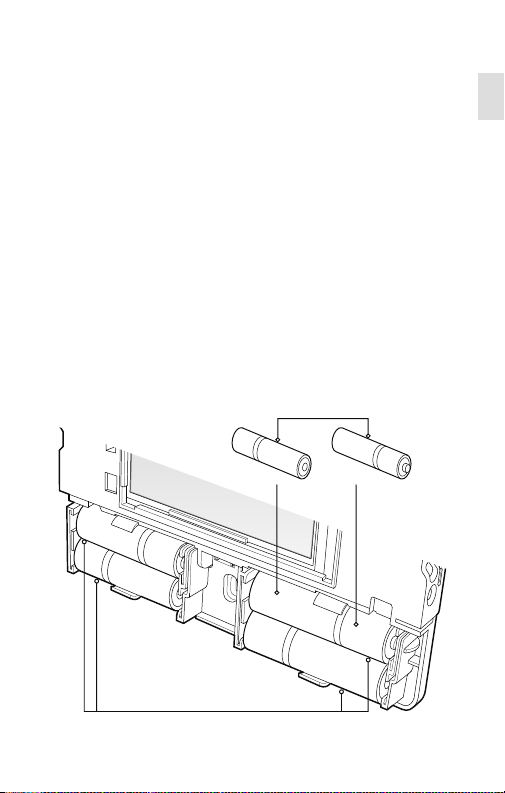
Power Supply
While the CT102 Thermostat can run without batteries on C-wire
power, you should install batteries as well to provide power to the
unit during outages.
1. Install four (4) AA alkaline batteries following the marked polarity
in the battery compartments. Insert the battery negative end rst
against the spring, then push the positive end in.
2. With all the wires connected and the unit attached to the wall, it
is time to turn the AC power back on. Reconnect the power at the
breaker you used to switch it o. The CT102 will power-up in the
OFF mode.
3. Trip the RESET button to implement the HVAC switch selections.
4. Your CT102 is not yet congured to operate your HVAC system.
You must now congure your thermostat (see page X.)
Battery Installation
AA ALKALINE BATTERIES
-
+
AA
AA
+
-
4 PROPERLY INSTALLED
AA ALKALINE BATTERIES
-
NEGATIVE
-
+
AA
AA
-
+
POSITIVE
+
13
Page 14

Installation Guide CT102
Setup
!
THERMOSTAT BATTERY CAUTIONS
• Always use new Alkaline batteries.
• Do not use rechargeable batteries of any type. They will no operate the
thermostat properly and may lead to damage.
• Do not mix old and new batteries.
• Do not mix battery types, for example Lithium with Alkaline.
• Do not dispose of batteries in re. Batteries may explode or leak.
• Always replace the batteries as soon as the “Low Batt” warning ashes. The
thermostat is a battery-powered device; you should replace the batteries
before they run out, as failure to replace batteries can result in excessive
heating or cooling of your house.
• Always replace the batteries once a year, even if the “Low Batt” indicator
does not ash. Replacing the batteries also helps to prevent leakage that
can corrode and damage the thermostat.
• If you are leaving your home for a month or more, you should replace the
batteries as a precaution against battery failure in your absence.
• Failing to replace the batteries when necessary could cause the thermo-
stat to lose power or malfunction. If the thermostat loses power, then the
thermostat will not control the temperature, which could result in your HVAC
system not functioning as you intended and lead to possible damage from
excessive heating or cooling.
• If the thermostat batteries fail with the heat OFF, this can result in NO HEAT
and possible frozen or broken pipes and water damage.
• If the thermostat batteries fail with the cool OFF, this can result in NO COOL
and could cause possible damage or excessive temperatures.
14
Page 15
Installation Guide CT102
MA
TE
1
1
Y
MENU
EN
EN
SETU
P
Setup
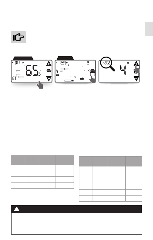
HVAC Setup
HVAC selection switches must be set rst (see page X), then
make sure the CT102 is powered up and the mode is set
to O.
Access HVAC Setup
MANUAL Screen
EMER
HOLD
HOLIDAY
TEMP
TEMPORARY
AUTO
F
MENU
1. Trip the RESET button (see page #) to implement the HVAC switch
selections.
2. With mode in O, touch Menu and then HVAC Setup.
3. Use Temperature Adjustment arrows to adjust the HVAC Setup
number. The display will show your selection and indicate the
number of stages you have selected.
4. During setup, 2nd stage will blink when both heat and cool have
2nd stages.
HVAC Setup Stage
Regular HVAC System
Heat
Cool
Stage
Stage
1 1 H1C1 1
2 1 H2C1 2
1 2 H1C2 3
2 2 H2C2 4
MENU Screen
RADIO
RADIO
FILTER
FILTER
SWING
DIFF
1
1
MATE
MATE
COOL
TRUE
AUTO
Screen
Display Select
CALIBRATE
PM
PM
F
F
SWING
RECOVERY ECON
TECALIBRA ON PROGRAM
Heat Pump HVAC system
HP
Stage
1 0 P1 A
2 0 P2 B
1 1 P1A1 C
1 2 P1A2 D
2 1 P2A1 E
2 2 P2A2 F
HVAC
SETUP
Aux
Stage
HEAT
COOL
2ND STG
Screen
Display Select
HVAC
SETUP
!
CAUTION
Do not change the HVAC setup or HVAC selection switches if the thermostat
is connected to a Z-Wave network. If you must change the HVAC system, rst
remove the thermostat from the network, change the HVAC setup, and then
reconnect the thermostat to the network.
15
Page 16

Installation Guide CT102
Setup
Test Installation
If you have a heat pump, leave the CT102 in O mode for 4
minutes before checking Cool.
Do not operate AC if the outside temp is below 65°F.
To Check Fan (If you connected the G wire)
1. Touch the fan icon on the HOME screen to turn the fan ON.
2. Verify that air is blowing from the system. Touch the fan icon again
to return to AUTO.
To Check Heat
1. Touch the temperature display to open the Manual screen.
2. Use the or arrows to set the mode to Heat.
3. From the Manual screen, touch the Temperature Up arrow until
the target temperature is 5º above room temperature. Allow the
system two (2) minutes to respond.
4. Verify that heat is blowing from the system. Return the target
temperature to a normal setting.
5. From the Manual screen, set the mode to O.
To Check Cool
1. Touch the temperature display to open the Manual screen.
2. Use the or arrows to set the mode to Cool.
3. Touch the Temperature Down arrow icon until the target temp is
5º below room temperature. Allow the system ve (5) minutes to
respond.
4. Verify that cool air is blowing from the system. Return the target
temperature to a normal setting.
5. From the Manual screen, set the mode to O.
16
Page 17

Wiring Diagrams
Radio Thermostat
17
Page 18

G
2 Wire Heat 3 Wire Heat 4 Wire Heat/Cool
5 Wire Heat/Cool
Detailed Wiring Diagrams
Installation Guide CT102
Wiring Diagrams
WIRES
C W RC W R GC W Y R G
HVAC
C
W
See Page 13
Multi-stage Cool
Multi-stage Heat
WIRES
C Wn Yn R G
HVAC
C
Wn
Go to Page 13
WIRES WIRES
R
C
Go to Page 13
G
R
Yn
HVAC
W
4 Wire Heat Pump
w/o Aux Heat
WIRES WIRES
C B or O Y R G C B or O AUXn Yn R G
HVAC
C
Go to Page 13
HVAC
G
C
R
B
O
or
W
Go to Page 13
G
R
Y
WIRES
C W Y RH RC
HVAC
G
C
R
Y
Go to Page 13
Multi-stage Heat Pump
w/ Multi-stage Aux Heat
HVAC
Wn
O
B
C
or
Go to Page 13
G
RC
RH
Y
W
G
R
Yn
18
Page 19

Installation Guide CT102
Wiring Diagrams
Step-By-Step Wiring Diagrams
3 Wire Heat GAS MILLIVOLT or 24VAC
System
1. Connect the R (or RH) wire to the
POWER
RH terminal. This connects the
heat power.
2. Connect the W wire to the W
terminal. This connects the heat.
CBOW YY2RHRC GAW2
THERMOSTAT
3. Connect the C wire to the C
terminal. Your HVAC system is now connected to the CT102.
4. Go to “Connect Your Wires” on page X.
4 Wire Heat
1. Connect the R (or RH) wire to the
RH terminal. This connects the
POWER
heat power.
2. Connect the W wire to the W
terminal. This connects the heat.
3. Connect the G wire to the G
CBOW YY2RHRC GAW2
THERMOSTAT
terminal. This connects the fan.
4. Connect the C wire to the C terminal. Your HVAC system is now
connected to the CT102.
5. Go to “Connect Your Wires” on page X.
5 Wire Heat/Cool
1. Connect the W wire to the W
terminal. This connects the heat.
POWER
2. Connect the Y wire to the Y
terminal. This connects the
cooling compressor.
3. Connect the RH or R wire to the
CBOW YY2RHRC GAW2
THERMOSTAT TERMINALS
RH terminal. This connects the
power.
4. Connect the G wire to the G terminal. This connects the fan.
5. Connect the C wire to the C terminal. Your HVAC system is now
connected to the CT102.
6. Go to “Connect Your Wires” on page X.
HVAC SYSTEM
C
W R
HVAC SYSTEM
W RCG
HVAC SYSTEM
W RCGY
19
Page 20

Installation Guide CT102
Wiring Diagrams
6 Wire Heat/Cool
1. Connect the W wire to the W
terminal. This connects the heat.
POWER
2. Connect the Y wire to the Y
terminal. This connects to the
cooling compressor.
3. Disconnect the Rc and Rh
CBOW YY2RHRC GAW2
THERMOSTAT TERMINALS
terminals by placing the
removing the Jumper Wire.
4. Connect the RH wire to the RH terminal and the RC wire to the RC
terminal. This connects power.
5. Connect the G wire to the G terminal. This connects the fan.
6. Connect the C wire to the C terminal. Your HVAC system is now
connected to the CT102.
7. Go to “Connect Your Wires” on page X.
Multi-stage Heat & Multi-Stage Cool
The CT102 can handle up to 2
stages of HEAT and 2 stages of
POWER
COOL.
1. Connect the W and W2 wires to
the W and W2 terminals. This
connects the stages of HEAT.
CBOW YY2RHRC GAW2
THERMOSTAT TERMINALS
2. Connect the Y and Y2 wires to
the Y and Y2 terminals. This
connects the stages of COOL.
3. Connect the RH or R wire to the RH terminal. This connects the
power.
4. Connect the G wire to the G terminal. This connects the fan.
5. Connect the C wire to the C terminal. Your HVAC system is now
connected to the CT102.
6. Go to “Connect Your Wires” on page X.
HVAC SYSTEM
W G
C
Y
*RC and RH disconnected
HVAC SYSTEM
W2
W G
C
Y
RH
RC
Y2
R
20
Page 21

Installation Guide CT102
Wiring Diagrams
4 Wire Heat Pump (heat/cool) without
Auxiliary Heat
1. Connect the O wire to the O
POWER
terminal or the B wire to the
B terminal. This connects the
change-over valve. If you have
both O and B, connect only the
CB OW YY2RHRC GAW2
THERMOSTAT TERMINALS
O wire to the O terminal and DO
NOT connect B to B terminal (see
the Wire Reference Table on page X for Trane terminal labels).
2. Connect the Y wire to the Y terminal. This connects the
compressor.
3. Connect the R wire to the RH terminal. This connects the power.
4. Connect the G wire to the G terminal. This connects the fan.
5. Connect the C wire to the C terminal. Your HVAC system is now
connected to the CT102.
6. Go to “Connect Your Wires” on page X.
HVAC SYSTEM
BGO
Y R
C
or
or
Multi-stage Heat Pump with MultiStage Aux Heat
The CT102 can handle up to 2
stages of Pump compression and 2
stages of AUX heat.
1. Connect O wire to the O terminal
or the B wire to the B terminal.
HVAC SYSTEM
BGO
C
POWER
or
or
CBOW YY2RHRC GAW2
THERMOSTAT TERMINALS
Y2AUX2AUX1
Y R
This connects the change-over
valve. If you have both O and B, connect only the O wire to the O
terminal and DO NOT connect B to B terminal (see Wire Reference
Table on page X for Trane terminal labels.).
2. Connect the AUX 1 and AUX 2 wires to the AUX 1 and AUX 2
terminals. This connects the auxiliary heat.
3. Connect the Y and Y2 wires to the Y and Y2 terminals. This
connects the compressor.
4. Connect the R wire to RH terminal. This connects the power.
5. Connect the G wire to the G terminal. This connects the fan.
6. Connect the C wire to the C terminal. Your HVAC system is now
connected to the CT102.
7. Go to “Connect Your Wires” on page X.
21
Page 22

Installation Guide CT102
HW
Wiring Diagrams
Accessory Wiring
Zoned Hot Water Heat
For Solenoid or Motor valves,
connect the wires based on the
diagrams to the correct terminal on
the CT102.
• USE ONLY IN HEAT MODE.
• The CT102 must be powered by
24v ac.
The third wire on your valve may be called 6, Y, or G (see the Wire
Reference Table on page X.
CT102
RH AW
R
WA
MOTOR VALVE
CT102
AR
R
WA
SOLENOID VALVE
22
Page 23

Installation Guide CT102
Wiring Diagrams
Wire Reference Table
Possible Wires What They Control
R or V or VR RH and RC Single power for HEAT and COOL
RH or 4 RH Power for HEAT (RH not connected to RC jumper clip
RC RC Power for COOL (RH not connected to RC jumper clip
W W Heat control
W2 W2 2nd stage HEAT or heat pump auxiliary heat
W3 W3 3rd stage HEAT or 2nd stage of 2 stage auxiliary heat
Y Y COOL control or 1st stage compression for heat pump
Y2 Y2 2nd stage COOL control or 2nd stage compression for
G or F G FAN control
C or X C 24VAC power (to power thermostat) NOTE: TRANE uses B
H H External Humidier
DH DH External De-Humidier
EX
B
O O Heat pump changeover (heat to cool, powered in cool)
B and O
E n/a Emergency heat (do not connect, tape o)
L n/a System monitor (do not connect, tape o)
T n/a Outdoor sensor (do not connect, tape o)
removed)
removed)
a heat pump
for this connection
EX external fresh air bae
B Heat pump changeover (cool to heat, powered in heat)
IMPORTANT: If there are both B and O wires (Trane pump
products) DO NOT CONNECT B to B terminal. Instead,
connect B to C terminal. If not a Trane product, tape o B.
23
Page 24

Installation Guide CT102
Wiring Diagrams
Lennox Heat Pump
V or VR or R RH Power for HEAT
M or Y Y COOL control
Y or W or W2 W2 2nd stage HEAT
F or G G Fan control
R or O O
X or X2 or C C
Trane Products [American Standard]
B C 24VAC power (to power thermostat)
W or W1 W2 2nd stage HEAT
X2 Emergency heat. Do not connect, tape o.
Zoned Hot Water
2 wire
R RH
W W
Motor Driven Valves
3 Wire
R or 5 RH (power)
W or 4 W (heat ON)
Y or G or 6 (the
3rd wire) A (heat OFF)
Solenoid Valves
3 Wire
R RH (power)
W A (heat ON)
Y or G
(the 3rd wire) W (heat OFF)
24
Page 25

CT102 OPERATION GUIDE
Table Of Contents
Product Overview ....................... 3
Device Parts #
Screens
Z-Wave
Connecting to a Z-Wave Network #
HVAC Setup
Power Sources
Initial Settings
Customization .......................... #
Manual Screen & Functions #
Menu Screen & Functions #
Programs Screen
Heat, Cool and Auto Settings #
Restoration Settings #
2
Page 26

Product Overview
Radio Thermostat
3
Page 27

Exterior View
STATUS
INDICATORS
TOUCH SCREEN
The CT102 Z-Wave thermostat operates via a high-quality,
easy-to-use touch screen. Simply touch your nger rmly
to the screen to set or adjust your CT102; the screen will
automatically light up and you will hear a beep. To avoid
scratching the screen, do not use a sharp or metallic
device.
RADIO
1
LINK
TARGETTEMP
PM
Su Mo Tu We Th Fr Sa
Product Overview
Device Parts
DAY
AUTO
F
HEAT
4
Page 28

Product Overview
PROGRAM
MENU
SWING
FILTER
PM
F
MATE
RADIO
1
TECALIBRA
ON
PROGRAM
MANUAL
HOME
Screens
Before you operate the CT102, familiarize yourself with the basic
control screens. The touch screen enables you to select (by touching)
an item and change it. All the CT102 functions are accessed through
these screens:
5
Page 29

Product Overview
TARGETTEMP
ON
DAY
PM
F
LINK
RADIO
1
Tu
AUTO
HEAT
TIME OF DAY
AND RELATIVE
HUMIDITY
CURRENT
ROOM
TEMPERATURE
FAN MODE
AND STATUS
THERMOSTAT
MODE
TARGET
TEMPERATURE
TEMPERATURE
CONTROLS
HOME*
RADIO
INDICATOR
Screens
The Home screen displays when the unit is operating. Features
you can control on the Home screen are temperature override, fan
mode, toggling the time and relative humidity display, and opening
the Manual screen.
HOME Screen
Touching the icon on other screens will return you to the previous screen.
*Home icon visable of Home screen only in O mode.
6
Page 30

Product Overview
MANUAL
EN
U
TE
MENU
AC
UP
TE
MATE
RADIO
1
1
Z-Wave
Connecting the CT102 to a Z-Wave® Network
The CT102 is a Z-Wave® compliant thermostat. It has an onboard
radio that can be connected to an existing Z-Wave® network. This
device can be used on a network with products from dierent
vendors.
1. Set your primary controller to INCLUDE mode to add the
thermostat as a node on your network (see your specic
controller’s User Manual for detailed instructions).
2. From the CT102’s Menu screen, touch MATE under the radio icon.
The Network Include screen displays a large r1.
AUTO
TEMPORARY
F
COOL
TRUE
AUTO
MENU
MENU
EMER
HOLD
HOLIDAY
TEMP
RADIO
RADIO
1
1
MATE
MATE
FILTER
FILTER
SWING
SWING
DIFF
CALIBRATE
PM
PM
RECOVERY ECON
TECALIBRA ON PROGRAM
3. Touch MATE again. This initiates the network connection (mating)
process. The MATE icon and the status indicator LEDs will blink.
When the CT102 has successfully joined a Z-Wave network, the
MATE icon is replaced by the LINK icon
RADIO
Similarly, when you are trying to disconnect
1
under the radio tower.
from (leave) a network, the LINK icon
disappears when the node has successfully
left the network.
4. Your controller indicates that the thermostat was successfully
added to its network (see your specic controller’s User Manual
for details.)
F
F
RADIO
1
HVAC
ET
SETUP
MATE
7
Page 31

Product Overview
Z-Wave Power Sources
Z-Wave and HVAC Setup
Do not change the HVAC setup or HVAC selection switches
if the thermostat is connected to a Z-Wave network.
If you need to change the HVAC system:
1. Remove the thermostat from the Z-Wave network.
2. Change the HVAC Setup selection. See Install Guide page 18 for
full instructions.
3. Connect the thermostat to the Z-Wave network.
Z-Wave and Power Supply
The thermostat’s node type is xed when it connects to
the Z-Wave network; if the C-Wire is not connected and is
only battery-powered when connecting to the network, the
thermostat will remain a frequent listening routing slave (FLiRS) node
until it is removed from the network.
When your thermostat is running on battery power, the Z-Wave
radio will turn o to help conserve battery life. The CT102 Z-Wave
radio module supports Z-Wave beaming, which allows other
devices in the network to wake up the Z-Wave module and accept
commands and then go back to sleep.
When your thermostat is running on C-Wire power, the Z-Wave radio
will stay on and actively help route messages within the Z-Wave
network. The thermostat’s node type is xed when it connects to
the Z-Wave network; if the C-Wire is present and powered when
connecting to the network, the thermostat will remain an alwayslistening node until it is removed from the network.
Z-Wave and Thermostat Program
To get the most out of your new thermostat, it needs to be paired
to a Z-Wave system. When you are paired to a Z-Wave system,
the Z-Wave application on your device controls your thermostat’s
programs. You can still temporarily override settings on the
thermostat itself, but otherwise you can control it remotely. No
Z-WAVE system? See “Customizing Programming” on page 18.
8
Page 32

Product Overview
TEMPORARY
HOLD
EMER
F
TEMP
HOLIDAY
MENU
AUTO
COOL
TRUE
AUTO
Initial Settings
Thermostat Program
EPA Recommended Energy-Eciency Program Settings
MORN DAY EVEN NIGHT MORN DAY EVEN NIGHT
6 am 8 am 6 pm 10 pm 6 am 8 am 6 pm 10 pm
70ºF 62ºF 70ºF 62ºF 78ºF 85ºF 78ºF 82ºF
The CT102 thermostat automatically includes EPA recommended
heating and cooling programs. If it does not t your needs, you can
adjust the programs instead. To run one of these preset programs,
simply set the thermostat mode to Heat or Cool.
Run Pre-Set Program
1. Set Time & Day (see page #)
2. Access the Manual screen by touching the Temperature on the
Home screen.
3. Set the mode to Heat or Cool.
4. Touch .
5. The unit is now running the program.
HEAT COOL
MANUAL Screen
9
Page 33

Product Overview
Initial Settings
Compressor Protection
The CT102 has a minimum cycle time of four (4) minutes to
protect your compressor from excessive wear from responding to
thermostat changes. The Home screen shows an hour glass and the
message “Please Wait...” during this time, and the compressor will
not come on until the four minute delay is over.
DAY
PM
RADIO
HOME SCREEN
1
LINK
Tu
TARGETTEMP
10
AUTO
ON
F
HEAT
PLEASE
WAIT...
Page 34

Customization
Radio Thermostat
11
Page 35

Customization
Manual Screen
The Manual screen enables you to make temporary changes to how
your CT102 operates.
Features you can control on the Manual screen: Thermostat Mode,
Fan Mode, Target Temperature Override, and more. See page 20 for
a full listing.
MANUAL Screen
AUTO
F
COOL
TRUE
AUTO
MENU
TEMPORARY
Target temperature
has been temporarily
overridden.
TEMP UP/TEMP
DOWN
Raises or lowers
the manual
override target.
RETURN
HOME
EMER
Enables emergency
heat for heat pump
systems.
MODE
Change Mode
Heat, Cool, Auto, Off
EMER
HOLD
HOLIDAY
HOLD
Maintains
the current
temperature.
TEMP
ROOM
TEMPERATURE
To access the MANUAL screen:
HOME
DAY
AUTO
RADIO
1
LINK
TARGETTEMP
PM
ON
F
HEAT
Tu
TARGET
TEMPERATURE
TEMPORARY
HOLIDAY
Runs the
Holiday program.
Touch the temperature on
the Home screen to open the
Manual screen.
12
Page 36

Customization
TEMPORARY
HOLD
EMER
F
TEMP
HOLIDAY
MENU
AUTO
COOL
TRUE
AUTO
Manual Screen
Manual Screen Functions
The Manual screen enables you to issue manual override commands.
Access Manual screen (see page 10)
MODE
TEMPERATURE
EMER
HOLD*
CURRENT
TEMPERATURE
HOLIDAY*
ADJUST
IMPORTANT: The Mode must be currently set to Heat or Cool to access
most functions on the Manual screen (see previous page for details).
Mode
The Mode settings for the CT102 are Heat, Cool, Auto, or O.
• Touch the Mode area once to step to the next mode.
• To return to the mode you were previously in, touch the Mode
area until the mode you were in appears.
• See page 18 for details to adjust Heat and Cool modes.
Temperature
• Touch the Temperature Adjust arrows to select your desired
target temperature.
• Touch when done.
Holiday
Holiday Enabled Holiday Disabled
This function enables the one-day Holiday setting of the current
program. This setting may have dierent start times and target
temperatures. Touch icon to toggle between Enabled and Disabled.
* These icons are not visible when the thermostat is connected to a Z-Wave network.
FAN
13
Page 37

Customization
Manual Screen Functions Cont.
EMER
Requires the CT102 HVAC TYPE be set to Heat Pump.
If you set your CT102 HVAC type to Heat Pump with the HVAC setup
program selected to enable auxiliary heat, the emergency function is
available on the Manual screen. Enabling Emer On disables the heat
pump and leaves auxiliary heat as your sole heating source.
Auxiliary heat is more expensive than the heat pump so use this
feature only if the heat pump cannot keep up or is defective. This
manual override stays active until you disable emer by switching the
thermostat to another mode.
EMER Enabled EMER Disabled
To Enable EMER
From the Manual screen, touch
EMER. The display shows Emer
On and the heat pump is
disabled.
Fan Control
AUTO
Auto Fan Mode Fan On
Auto Mode
The fan operates automatically
with the HVAC system and the
thermostat.
• Switch to Auto by touching the
again.
Hold
Hold Enabled Hold Disabled
This function causes the thermostat to attempt to keep the room
at the current room temperature. Touch icon to toggle between
Enabled and Disabled
To Disable EMER
From the Manual screen, touch
the Mode area and cycle through
until Heat is displayed again.
Fan On
The fan will run continuously
in this manual override until
switched back to Auto.
• To use the fan for simple
ventilation, turn the thermostat
mode to O (see Mode section
on previous page)
• Touch to turn the Fan On.
14
Page 38

Customization
RECOVERY
DIFF
SWING
FILTER
PM
F
MATE
RADIO
1
Tu
PROGRAM
CALIBRATE
FILTER
RADIO
DIFFERENTIAL
CALIBRATION
TIMER
SET
TIME
ICON
SWING
FUNCTION
DAY
7 DAY
PROGRAM
CHIRP
SET
LOCK
PROGRAM
TEMPERATURE
HOME
Return to
Manual screen
SET
O
C OR OF
RECOVERY
F
MENU
AUTO
COOL
TRUE
AUTO
Menu Screen
The Menu provides access to many features and settings of the
CT102.
Features you can control on the Menu screen are ºF / ºC setting,
thermostat calibration, lter replacement reminder, and more. See
page 25 for more Menu screen options..
MENU Screen
To access the MENU screen:
HOME
DAY
PM
Tu
RADIO
1
LINK
TARGETTEMP
Touch the temperature on
1
the Home screen to open
the Manual screen.
AUTO
ON
F
HEAT
MANUAL
EMER
HOLD
HOLIDAY
TEMP
COOL
TRUEAUTO
AUTO
F
MENU
TEMPORARY
2
Touch Menu to display the
Menu screen.
15
Page 39

HVAC
SETUP
DIFF
SWING
FILTER
PM
F
MATE
RADIO
1
CALIBRATE
RECOVERY ECON
SWING
FILTER
PM
F
MATE
RADIO
1
TECALIBRA ON PROGRAM
Menu Screen Functions
Access MENU screen (see page 9)
Customization
Menu Screen
Time
Swing
Filter
Dierential
Mate
Calibrate
Set Time Of Day, Set Fº or Cº
Sound see page #
Recovery
Econ Or Fast
Program*
Swing (HVAC Cycling Rate)
This feature enables you to set the acceptable variance in
temperature between the CT102’s setting and the current room
temperature before the heating or cooling system will turn on. The
Swing range can be from 0.5 to 4.0F (.25 to 2C). For example, if Swing
is set to 2.0°F and the CT102 is set to 70°F target temperature, the
heat cycle will start when the room temperature drops to 68°F.
Similarly, the cooling system will start when the room temperature
increases to 72°F. The HVAC runs until the room reaches the target
temperature, and then shuts o.
To set Swing
1. From the Menu screen, touch Swing.
2. Touch Time Adjustment arrows to set the SWING from 0.5°
to 2.0°F. The HVAC will run more frequently at .5°F and less
frequently at 2°F. The default is 1°F.
3. Touch to return to the Menu screen.
Filter
To help you remember to replace your air lters, use the lter
replacement reminder count-down (in days). Setting this value to 0
disables the reminder.
16
* These icons are not visible when the thermostat is connected to a Z-Wave network.
Lock
˚F ˚C Set
Sound
HVAC Setup*
Page 40

Customization
Menu Screen Functions Cont.
Set Filter Reminder
1. From the Menu screen, touch Filter.
2. Touch the Days counter to set a value between 0 and 999 days.
Dierential
Used for multiple stage systems only. Not available on-screen for single
stage systems.
The Dierential is the number of degrees between the room
temperature and the target temperature at which the 2nd stage
will engage to bring the room temperature back to the target. The
default is 2°F. The programmable range is 2°F to 6°F (1°- 3°C).
To Change the Dierential
1. From the Menu screen, touch DIFF.
2. Use the or arrows to set the Dierential value. 2°F is
standard for very cold climates, and 4°F for warm climates.
3. Touch to return to the Menu screen.
Mate
This icon indicates that the CT102 is not connected to a Z-Wave
network. For instructions on connecting, see page 6.
Calibrate
Your thermostat was accurately calibrated at the factory to ±1° F of
actual ambient temperature. However, you can change the display
temperature to match that of a previous thermostat, or to match
another thermostat already in your home. The range of change is
from -6°F to +6°F (-3°C to +3°C).
To change your Thermostat Calibration:
1. From the Menu screen, touch Calibrate.
2. Use the Temperature Adjust arrows to adjust the displayed
temperature up or down, as desired in 0.5° (F or C) increments.
The temperature value in the lower left corner of the screen
adjustments to show the changed temperature value. The
central display shows the modied temperature reading that will
be displayed on the Home screen and used as the new room
temperature.
3. Touch to return to the Menu screen.
17
Page 41

Customization
Menu Screen Functions Cont.
Recovery
The Recovery function determines whether your HVAC system will
attempt to meet the programmed target temperature quickly.
Economy Recovery (Slower) Fast Recovery
Touch Recovery icons to toggle between settings.
HVAC Setup
When the unit mode is O (see page 20 for details), touch HVAC
Setup to enter the HVAC settings screen. For details on using this
screen, see the CT102 Installation Guide.
Lock
The Lock feature prevents thermostat changes. Unlock allows all
changes; Partial lock allows temporary temperature adjustments;
Full lock prevents all changes.. The CT102 has 3 lock modes:
Unlock Partial Lock Full Lock
Partial Lock
• From the Menu screen, touch Unlock for 5 seconds. The Lock
icon changes to show Partial Lock. In this mode, you can only
temporarily override the CT102 target temperature with the
Temperature Adjust arrows.
Full Lock
• From the Menu screen, touch the Partial Lock for 5 seconds
to show the Full Lock icon. Once locked, you cannot make any
changes; the CT102 only responds to touching and Menu.
Unlock
• If in Partial Lock, touch and hold icon for 5 seconds to switch to
Full Lock.
• If in Full Lock, touch and hold icon for another 5 seconds. Each 5
second touch and hold must be separate.
NOTE: Unlocking has to go this direction:
Unlock > Partial Lock > Full Lock > Unlock
• Touch to return to the Manual screen.
18
Page 42

SWING
FILTER
PM
F
MATE
RADIO
1
TECALIBRA ON PROGRAM
F
MENU
AUTO
COOL
TRUE
AUTO
Menu Screen Functions Cont.
Set Time, ºF/ºC, or Sound
Access the MENU screen:
HOME
RADIO
1
LINK
TARGETTEMP
DAY
AUTO
PM
ON
F
HEAT
Tu
MANUAL
EMER
HOLD
TEMP
HOLIDAY
TEMPORARY
AUTO
F
COOL
TRUEAUTO
MENU
Customization
Set Time Of Day
• Touch arrows to
set the current
time.
• Touch and hold
an arrow to move
in 15 minute
increments.
TIME ºF / ºC
MENU Screen
Set Fº or Cº
• Toggle between
the ºF, ºC to switch
back and forth
SOUND
Sound
When enabled, the
chirp sounds when
you change to a new
screen or change a
setting.
Sound On
Sound O
19
Page 43

Customization
DAY
PM
F
COPY DAY
HOLIDAY
Tu
DAY
PM
F
Tu
HOME
Return to
MENU screen
SET
PROGRAM
DAY
TEMP UP/
TEMP DOWN
SET
TIME
SLOT
SET
PROGRAM
TIME
COPY CURRENT
DAYS PROGRAM
TO NEXT DAY
Program Screen
The Program screen manually controls your settings when not using
a Z-Wave system.
Features you can control on the Program screen are set program
start time, set time slot, target temperature, and more. See page 18
for more details.
PROGRAM Screen
20
When the thermostat is not connected to a Z-Wave
network, you can change the programs that the
thermostat runs.
If the thermostat is connected to a Z-Wave network,
manual programming is disabled, and is instead
controlled by the Z-Wave network.
Page 44

Customization
F
MENU
AUTO
COOL
TRUE
AUTO
HVAC
SETUP
Programs Functions
Access Heat, Cool, & Auto Programs
Heat, Cool and Auto programs are separate. Repeat these steps as
necessary for each program.
Make sure the current Mode is set to either Heat, Cool
or Auto, depending on which program you want to adjust
(page 20 for details).
HOME
DAY
PM
RADIO
1
LINK
TARGETTEMP
Tu
Touch the
temperature on
the Home screen
MANUAL
AUTO
ON
F
EMER
HEAT
HOLD
HOLIDAY
TEMP
Touch Menu to
21 3
open the Menu
screen.
TEMPORARY
MENU
AUTO
F
COOL
TRUE
AUTO
MENU
RADIO
RADIO
1
1
MATE
MATE
PM
PM
FILTER
FILTER
SWING
SWING
DIFF
CALIBRATE
RECOVERY ECON
TECALIBRA ON PROGRAM
Touch Program to
open the Program
screen.
to open the
Manual screen.
Program Schedule Recommendations
The CT102’s exibility lets you create programs that meet your
specic needs:
7 Day
Dierent programs for every day of the week, to suit changing
schedules
5 – 2
One program for routine workdays, and a separate one for
weekend days.
5 – 1 – 1
One program for routine workdays, and separate programs for each
weekend day
F
F
HVAC
SETUP
21
Page 45

To Change Heat, Cool, & Auto Programs
HOLIDAY
MORN
AM
F
COPY DAY
Tu
PROGRAM
COOL
TRUE
AUTO
1. Select the Day 1 you want to
program. Touch the day of the
week area to cycle through
the days to the desired day.
2. Select the Time Slot 2 you
want to program. Touch the
time slot area to cycle through
to select the desired period.
3. Set the desired start time
of that time slot. Touch the
time arrows 3 to select the
desired period’s starting time.
Hold down time arrow for fast
time scrolling.
4. Select the desired target
temperature for that time
slot. Touch the Temperature
Adjust arrows 4 to select the
desired period’s temperature.
CURRENT PROGRAM’S
START TIME
3
PROGRAM SCREEN
6
5
TIME SLOT
Customization
Modify Programs
• Repeat Step 2 - 4 to set
remaining Time Slots.
5. Touch Copy Day 5 once.
The settings for the current
day will be copied to the next
day, which will appear on the
screen. Make any necessary
adjustments.
NOTE: Hold down Copy Day
for 3 seconds to copy to all 7
days.
6. Touch the Day eld until
Holiday 6 is displayed. Follow
steps 2-4 to dene how the
program should run when the
Holiday setting is enabled.
7. Touch to return to the
Menu screen.
PROGRAMMED
TARGET
TEMPERATURE
2
4
1
Not Blinking = room at target temperature
22
Blinking = heating/cooling in progress
CURRENT MODE
Page 46

Customization
RADIO
1
MENU
AUTO
MANUAL
MENU Screen
MANUAL
RADIO
1
MATE
MENU
Restoring Settings
Display Thermostat Firmware & Radio Module Versions
1. Switch the thermostat to O Mode (see page 20 for details).
2. Press and hold
the Temperature
Adjust down
arrow for three (3)
seconds. The icon
is not visible in
3. The thermostat’s
rmware version
displays in the
Mode area of
screen.
4. Press the
Temperature
Adjust down arrow
to display the
thermostat’s radio
module version.
O Mode.
5. Press to return to the Manual screen.
Restore Thermostat & Z-Wave Module to Factory Default
1. Switch the thermostat to O Mode (see page 20 for details).
2. Press and hold the lower left corner of touch screen for ve (5)
seconds. The thermostat then resets itself, displays its current
rmware version, and restarts in O Mode.
Restore Z-Wave Module to Factory Default
1. From the Menu screen, touch Mate icon.
The Radio screen appears.
2. Touch & hold Mate icon ten (10) seconds
until you hear a beep. The thermostat will
restore the Z-Wave module to the factory
default settings.
Display Days Since Last Reset
1. Switch the thermostat to O Mode
(see page 20 for details).
2. Press & hold Temperature Adjust up
arrow, and the upper left will show the
letter “b” followed by three numbers.
The numbers indicate the days since the
device was last reset.
23
Page 47

Customization
C
B
O
W
W2
Y
Y2
RH
RC
G
A
AU
X
1
2
R
E
S
E
T
?
CU
S
TOM
ER
SE
R
VI
C
E
RESET
Restoration Settings
Reset
The RESET trigger re-boots the CT102 processor. It does not aect
the target temperatures that have been stored in permanent
memory.
1. Remove the CT102 cover.
2. Using a narrow pointed implement, trip the Reset trigger.
24
Page 48

CT102 THERMOSTAT
Z-WAVE® REFERENCE
Page 49

CT102 Thermostat
Z Wave
Z-Wave® Reference
The CT102 can work in the same network with any other certied
Z-Wave device, regardless of manufacturer/vendor. See your specic
Z-Wave® controller’s User Manual for detailed instructions on
operating your thermostat through the network.
Behavior Note: When power is rst applied to this device
it will broadcast a Hail message followed by a Node
Information frame. This behavior is to maintain backwards
compatibility with older controllers that work with this line
of devices.
Advanced Z-Wave® Information
The CT102 supports compliant mapping of the Z-Wave® BASIC_
COMMAND_CLASS to the CT thermostat “Energy Saving” and
“Comfort Mode” as follows:
• Basic Set (Value = 0x00) = Set Energy Saving Mode
• Basic Set (Value = 0x01-0x63 & 0xFF) = Set Comfort Mode
Energy Savings applies a 4° F setback to the existing set point
temperature to comply with EPA recommendations for energy
savings.
®
2
Page 50

CT102 Thermostat
Z Wave
Anti-theft
The Anti-Theft Command Class disables a subset of supported/
controlled command classes in the thermostat if the thermostat is
being disconnected from and reconnected to a Z-Wave network.
(This thermostat supports version 2 of the Anti-Theft Command
Class.) This command class is typically used when installing a
thermostat in a public location, such as a hotel room or conference
center. The command class allows the user to lock the thermostat to
the actual Z-Wave network and to render it useless if it is removed
from the local network without being unlocked. Another application
would be to protect service-provider-owned products from leaving
the service providers network before they are paid for.
Disabled Commands With Engaged Anti-Theft protection
Basic Command Clock Command
Indicator Command Manufacturer Specic Command
Multilevel Sensor Command Thermostat Mode Command
Thermostat Operating State
Command Thermostat Fan Mode Command
Thermostat Fan State Command Thermostat Setpoint Command
Version Command Conguration Command
Battery Command Association Command
Multi Channel Command
Anti-theft Command
(Only supported if a humidity sensor is
present.)
®
3
Page 51

CT102 Thermostat
Z Wave
Conguration Parameters
This device supports the following Conguration Parameters:
Name Set/Get Default Values
1 Temp Reporting Threshold Set/Get 2 0 to 4
2 HVAC Settings Get Only N/A see below
3 Utility Lock Enable/Disable Set Only 0 0 to 127
4 C- Wire/Battery Status Get Only N/A 0 or 1
5 Humidity Reporting Threshold Set/Get 2 0 to 3
6 Auxiliary/Emergency Set/Get 0 0 or 1
7 Thermostat Swing Temp Set/Get 2 1 to 8
8 Thermostat Di Temp Set/Get 4 4 to 12
9 Thermostat Recovery Mode Set/Get 2 1 or 2
10 Temp Reporting Filter Set/Get see below
11 Simple UI Mode Enable/Disable Set/Get 1 0 or 1
12 Multicast Enable/Disable Set/Get 0 0 or 1
1. Temperature Reporting Threshold (8-bit)
This value determines the reporting threshold when association
reporting is enabled. Unsupported values are ignored.
Value
Treshhold
2. HVAC Settings (32-bit)
Byte 1 = HVAC Setup: Normal (0x01) or Heat Pump (0x02)
Byte 2 = Aux Setup (Gas (0x01) or Electric (0x02)) & Number of
Byte 3 = Number of Heat Pump Stages
Byte 4 = Number of Cool Stages
3. Utility Lock (8-bit)
If set to 0, the utility lock is disabled. All other values (1-255) enable
the utility lock.
0 1 2 3 4
Disabled Disabled 0.5°F 1.0°F 1.5°F
Auxiliary Stages (Heat Pump)/Number of Heat Stages
(Normal)
®
4
Page 52

CT102 Thermostat
Z Wave
4. C-Wire/Battery Status (8-bit)
If 0x01, the thermostat is powered by a C-wire. If 0x02, the
thermostat is powered by batteries.
5. Humidity Reporting Threshold (8-bit)
This value determines the reporting threshold when association
reporting is enabled. Unsupported values are ignored.
6. Auxiliary/Emergency (8-bit)
If set to 0, auxiliary / emergency heat is disabled. All other values
(1-255) enable auxiliary / emergency heat. This can only be
enabled when the thermostat is set to Heat Pump mode.
7. Thermostat Swing Temp
The thermostat swing temperature is in units of 0.5 degrees
Fahrenheit. A value of 0x01 is 0.5F and 0x02 is 1.0F. The supported
values may vary from thermostat to thermostat but typically the
allowed values are 0.5F (0x01) to 4.0F (0x08).
8. Thermostat Di Temp
The thermostat dierential temperature is in units of 0.5 degrees
Fahrenheit. A value of 0x04 is 2.0F and 0x06 is 3.0F. The dierential
temperature must be an integer value. Non-integer values, such
as 1.5F (0x03), should not be used. The supported values may vary
from thermostat to thermostat but typically, the allowed values are
2.0F (0x04) to 6.0F (0x0C).
9. Thermostat Recovery Mode
The Thermostat Recovery Mode can be either fast (0x01) or
economy (0x02).
®
5
Page 53

CT102 Thermostat
10. Temp Reporting Filter (16-bit)
Set Command Denition
7 6 5 4 3 2 1 0
Command Class = COMMAND_CLASS_CONFIGURATION
Command = CONFIGURATION_SET
Parameter = 0x0A
Default RESERVED Size = 0x04
Precision (0x00) Scale Bound Size (0x01)
Temperature Filter Lower Bound
Precision (0x00) Scale Bound Size (0x01)
Temperature Filter Upper Bound
• Parameter (8-bit)
The parameter is set to 10 (0x0A) for the temperature
reporting lter.
• Default (1-bit)
If the default bit is set, the upper bound is zero (0) and the
lower bound is 124. This disables the lter.
• Size (3-bit)
The Size eld must be set to 4 (100b).
• Precision (3-bits)
The precision eld describes the precision of the temperature
lter value. The lter must be zero (0x00).
• Scale (2-bits)
The scale eld indicates the temperature scale used: 0
indicates Celsius and 1 indicates Fahrenheit.
• Bound Size (3-bits)
The size eld indicates the number of bytes used for the
temperature lter value. This eld must be one (0x01).
• Temperature Filter Lower Bound (8-bit)
The thermostat will report ambient temperature changes for
temperature values less than the lower bound. This eld must
be between 0F and 124F. By default, this value is 124F (report
all temperature changes).
Z Wave
®
6
Page 54

CT102 Thermostat
Z Wave
• Temperature Filter Upper Bound (8-bit)
The thermostat will report ambient temperature changes for
temperature values greater than the upper bound. This eld
must be between 0F and 124F. By default, this value is 0F
(report all temperature changes).
Thermostat Reporting Filter Report Command Denition
7 6 5 4 3 2 1 0
Command Class = COMMAND_CLASS_CONFIGURATION
Command = CONFIGURATION_SET
Parameter = 0x0A
Precision (0x00) Scale Bound Size (0x01)
Temperature Filter Lower Bound
Temperature Filter Upper Bound
• Parameter (8-bit)
The parameter is set to 10 (0x0A) for the temperature
reporting lter.
• Temperature Filter Lower Bound (8-bit)
The thermostat will report ambient temperature changes for
temperature values less than the lower bound. This eld must
be between 0F and 124F. By default, this value is 124F (report
all temperature changes).
• Temperature Filter Upper Bound (8-bit)
The thermostat will report ambient temperature changes for
temperature values greater than the upper bound. This eld
must be between 0F and 124F. By default, this value is 0F
(report all temperature changes).
11. Simple UI Mode Enable / Disable
If set to 0, Simple UI mode is disabled. If set to 1, Simple UI mode
is enabled.
®
12. Multicast Enable/Disable (8-bit)
If set to 0, Multicast is disabled. If set to 1, Multicast is enabled.
7
Page 55

Product Name: CT102
Document Title: CT102_ZW_IB_12feb15.ai
Document Type Code: IB
Part Number: 1503-007
15feb15 initial release mtf
How to join a
Z-Wave® Network
The CT102 is a Z-Wave® compliant thermostat. It has an onboard radio that can be mated with
an existing Z-Wave® network. To connect to a network follow these steps:
1) Set your primary controller to INCLUDE mode to add the thermostat as a node on your
network (see your specific controller’s User Manual for detailed instructions).
2) Touch the main temperature display to bring up the
manual screen. Touch the MENU icon. Touch the
MATE button on the MENU screen. A large r1 will be
displayed.
3) This will bring you to the network joining screen.
Confirm by touching MATE again. This will initiate the
mating process. The MATE icon and the status indicator
LEDs will blink.
4) When a device has joined a network the LINK icon
will appear under the radio tower. Similarly, when you
are trying to leave a network, the icon LINK will disappear when the node has successfully left the network.
5) Your controller will indicate the thermostat was
successfully added to its network (see your specific
controller’s User Manual for details.)
1503-007
FCC and IC Statement
FCC Regulatory Information:
NOTE: This equipment has been tested and found to comply with the limits for a Class B
digital device, pursuant to Part 15 of the FCC Rules. These limits are designed to provide
reasonable protection against harmful interference in a residential installation. This equipment
generates, uses, and can radiate radio frequency energy and, if not installed and used in
accordance with the instruction, may cause harmful interference to radio communications.
However, there is no guarantee that interference will not occur in a particular installation. If
this equipment does cause harmful interference to radio or television reception, which can be
determined by turning the equipment off and on, the user is encouraged to try and correct
the interference by one or more of the following measures:
a) reorient or relocate the receiving antenna,
b) increase the separation between the equipment and receiver,
c) connect the equipment into an outlet on a circuit different from that to which the receiver is
connected.
Consult the dealer or an experienced radio/TV technician for help.
IC Regulatory Information:
This Class B digital apparatus meets all requirements of the Canadian Interference Causing
Equipment Regulations. Operation is subject to the following two conditions: (1) this device
may not cause harmful interference, and (2) this device must accept any interference
received, including interference that may cause undesired operation of the device. Cet
appareillage numérique de la classe B répond a toutes les exigences de l’interférence
canadienne causant des règlements d’équipement. L’opération est sujette aux deux conditions suivantes: (1) ce dispositif peut ne pas causer l’interférence nocive, et (2) ce dispositif
doit accepter n’importe quelle interférence reçue, y compris l’interférence qui peut causer
l’opération peu désirée.
WARNING: Changes or modifications to this receiver not expressly approved by RTCOA void
the user’s authority to operate this equipment.
FRONT
This device complies with Industry Canada’s licence-exempt RSSs. Operation is subject to the following two conditions:
(1) This device may not cause interference; and
(2) This device must accept any interference, including interference that may cause undesired operation of the device.
Le présent appareil est conforme aux CNR d’Industrie Canada applicables aux appareils radio
exempts de licence. L’exploitation est autorisée aux deux conditions suivantes :
(1) l’appareil ne doit pas produire de brouillage;
(2) l’utilisateur de l’appareil doit accepter tout brouillage radioélectrique subi, même si le
brouillage est susceptible d’en compromettre le fonctionnement.
Page 56

Statement Of Use
100% Compatible with all popular residential HVAC systems: 24VAC single stage
and two stage conventional heating systems (gas, oil, electric), heat pumps with
up to two stages of heat and up to two stages of auxiliary heat (electric or fossil),
zoned forced air and zoned hot water (2 or 3 wire), millivolt systems (with a 1224V AC or DC source), one or two stage cooling, and hybrid systems. Do not use
this thermostat with with line voltage heating systems.
© 2015 Radio Thermostat Company of America. All rights reserved.
 Loading...