

Page 1
Install guide i29 rev.3
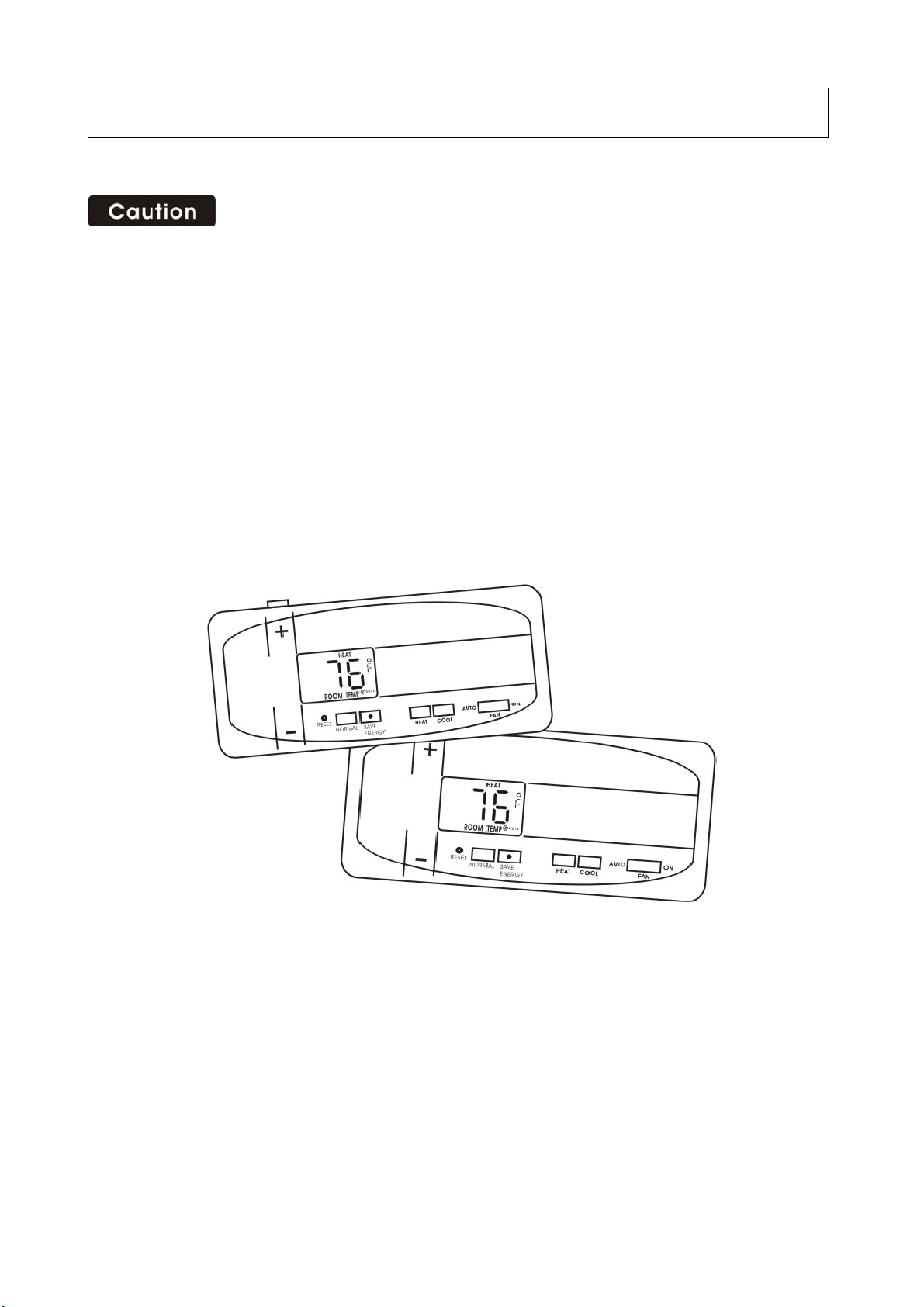
Your thermostat is a precise instrument, take care.
Turn off electricity to the appliance before installing or servicing thermostat or any part of the
system.
Do not turn electricity back on until work is completed.
Do not short (jumper) across electric terminals at control on furnace or air conditioner to test
the system. This will damage the i29 Master Thermostat (Wall Unit) and void your warranty.
All wiring must conform to local codes and ordinances.
All Thermostats are designed for use with 24 volt AC and millivolt systems. The Wall Unit
should be limit to a maximum of 1.0 amps, higher amperage may cause damage to the Wall
Unit.
1
Page 2
Install guide i29
You will need a small Phillips screwdriver and possibly a drill with 3/16-in. (4.8mm) bit for
mounting the i29 Master Thermostat (Wall Unit).
The i29 Wireless Thermostat system is
made of two parts – The i29 Master Thermostat (Wall Unit) and
the Slave Thermostat. (You can be purchased it at Home Depot). You will firs t install the Wall
Unit and then configure the Thermostat.
To avoid electrical shock and to prevent damage to the furnace, air
conditioner, and all thermostats, disconnect the power supply
before beginning work.
This can be done at the circuit breaker, or at the appliance.
Replacement installations - You can mount the Wall Unit in place of the old thermostat.
Remember the “C” power wire is required for operation this supplies 24VAC to the transmitter in
the Wall Unit and allows continuous communication with the Slave Thermostat. Because the i29
system is wireless it is easiest to mount the Wall Unit next to the HVAC unit in the basement attic or
HVAC closet even in a replacement installation.
New Installation or Change of location from Wall to HVAC
We recommend the WALL UNIT unit be installed in the same area and close to the HVAC location
so it can be wired directly to the HVAC’s thermostat terminals. The WALL UNIT unit has no
temperature sensing devices but still should not be mounted outside or where it would be exposed
2
Page 3
to weather conditions. It can be mounted at any angle on the wall.
24VAC Power – The Wall Unit REQUIRES the HVAC24VAC power wire (C) to work. If the C
wire is not available at a previous wall installation, the C wire must be added or the Wall Unit
should be mounted at the HVAC location where the C wire power is always available.
If you are going to place the Wall Unit in the
same location as the old thermostats…
Switch electricity to the furnace and air
conditioner OFF; then proceed with the following
steps.
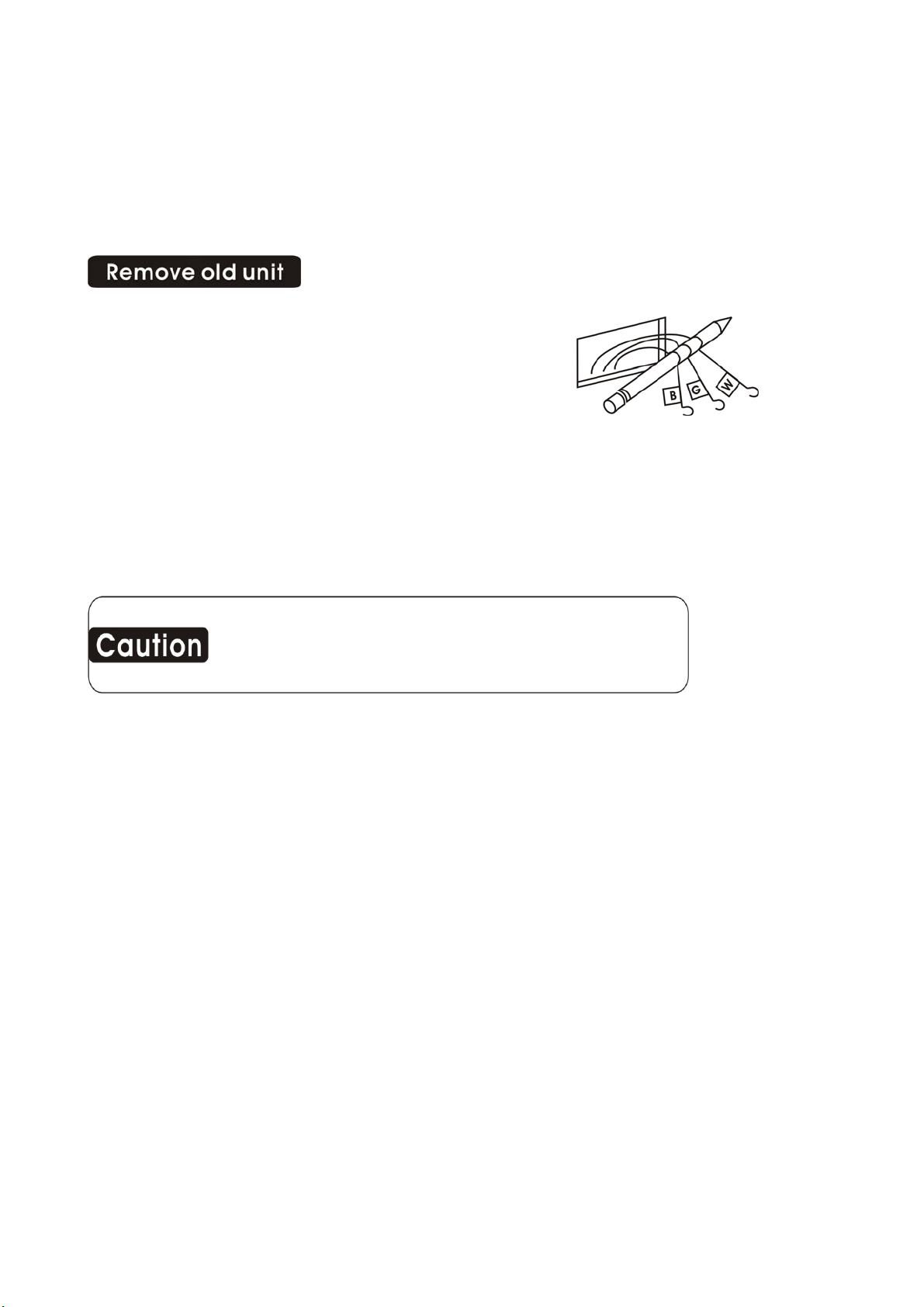
Remove cover from old thermostat. Most are
snap-on types and simply pull off. Some have locking screws on the side or front. These must
be loosened. Note the letters printed near the terminals. Attach labels (enclosed) to each wire
for identification.
IMPORTANT: LABEL ALL WIRES BEFORE DISCONNECTING THEM!
Wires must be labeled before they are removed. THERE IS NO STANDARD
COLOR CODE. When removing wires from their terminals, ignore the color of
the wires since these may not comply with any standard.
Read instructions carefully before removing any wiring from existing thermostat.
Label the wires one at a time. You must label all the wires before you proceed. With all wires
labeled, remove them from the old unit.
Make sure the wires do not fall back inside the wall. You can wind them around a pencil to
keep them from falling.
Loosen all screws on the old thermostat and remove it from the wall.
Fill wall opening with non-combustible insulation to prevent drafts.
If you are going to locate the Wall Unit at the HVAC…
Switch electricity to the furnace and air conditioner OFF; then proceed with the following
steps.
Open the service cover of your HVAC system and locate the thermostat terminals.
Remove any existing wire and run new thermostat wire to a convenient location for the i29
Wall Unit.
Note what color is connected to what terminal of the HVAC system.
3
Page 4
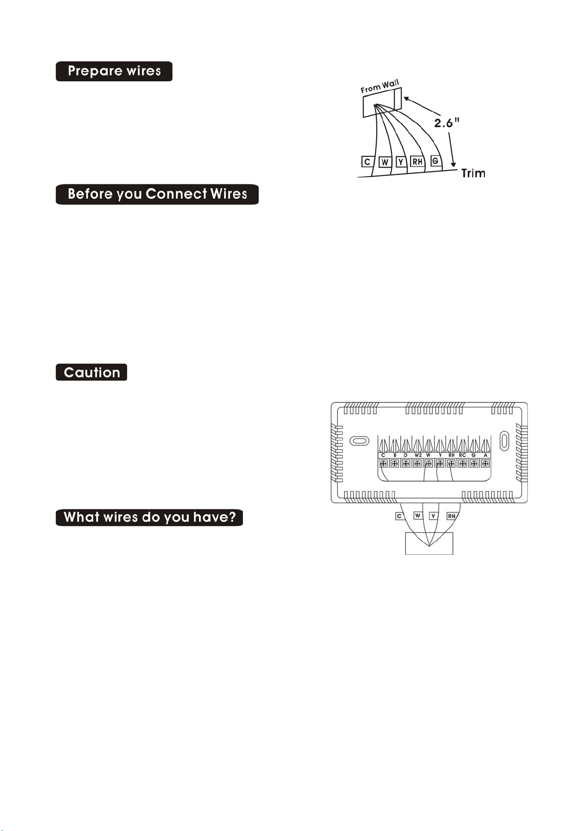
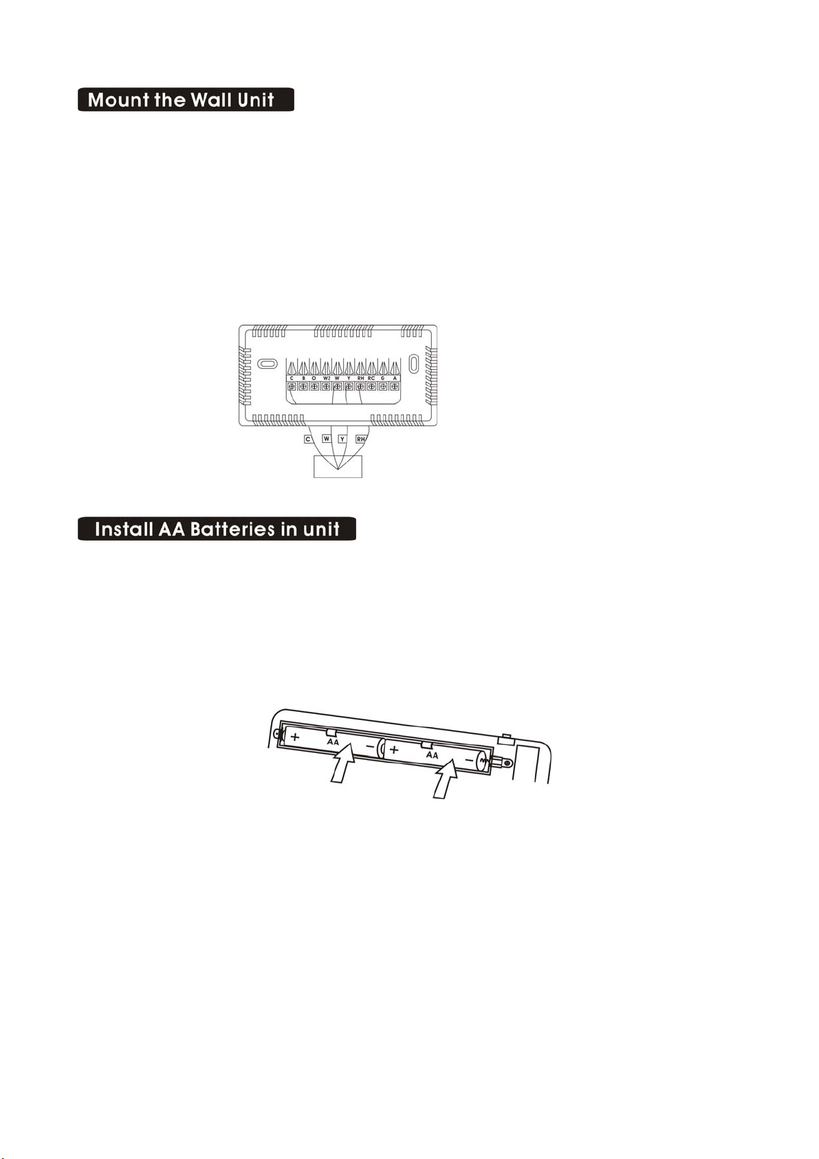
You will need at least 2.6” of wire for each of your
connections to the Wall Unit.
If you do not have enough wire, splice additional
wire to allow enough slack.
Fan out wires below the hole as shown.
Please follow these guidelines for safe and secure wire connections.
Easy Terminals do not require stripping the wire.
Clip any bare wire from previous installation.
Take care not to damage the labels for each wire in handling.
Fan wires out as illustrated with Wall Unit below the wall opening.
Wires will dress behind the Wall Unit and up over the terminal area.
Use the Step-By-Step diagram as your guide.
Do not bunch wires behind Wall Unit. Feed slack back into the wall opening.
Do not allow wires to touch each other or parts on thermostat.
Insert the wire in the terminal and tighten
the screw securely.
You will need to set Configuration jumpers
per the Step-By-Step diagram. A needle-nose
plier may be required to modify jumper
positions.
Determine which step-by-step wiring diagram below
you should use. Make sure your wires are labeled.
This may require you to find the ‘other end’
connection for each wire on your heating or air conditioning equipment and read the label there.
The Wall Unit must have the 24VAC to operate. This is available as the C wire at the HVAC or a
24VAC adapter can be used connected to the RH and the C terminal.
4
Page 5
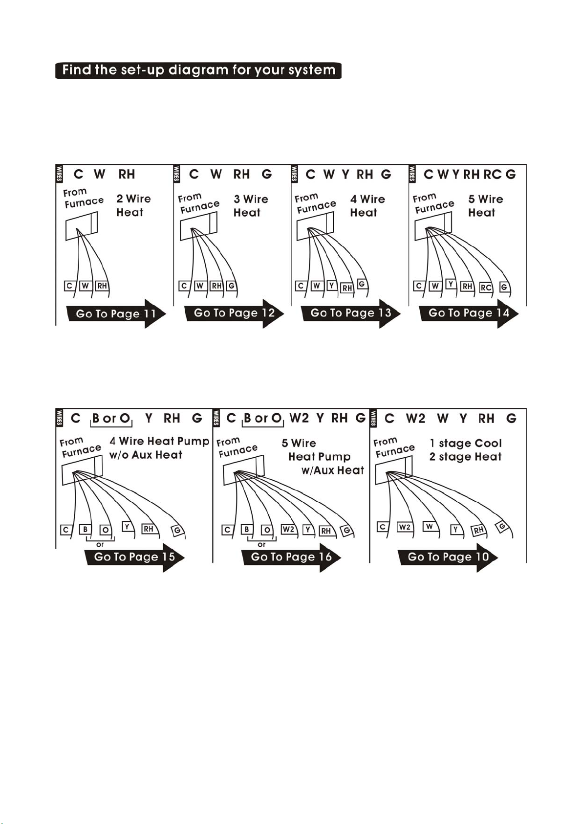
·Find the reference page with your wiring diagram and jumper set-up information. Remember,
the C wire or 24vdc power is required for the Wall Unit.
If you combination of wires is not above you can use the wiring table on pages 17-18 to
determine your connections, or call our USA support line at 1-877-505-2353 for help.
5
Page 6
Hold the Wall Unit against the wall, with the wires coming over the top above terminal block.
The unit will back cover the hole in the wall.
Position Wall Unit for best appearance. Use the optional stand-offs if more space for wires is
needed behind.
Attach the unit to the wall with the screws provided.
If you are mounting the unit to sheet rock or if you are using the old mounting holes, use the
plastic anchors provided. Drill a 3/16-in.
(4.8mm) hole for the insert at each screw location, then mount the base.
The Wall Unit requires 2 AA batteries for power loss backup.
Install 2 AA alkaline batteries according to the polarity noted in the compartment.
Press the RESET button to clear transient program memory.
NOTE: Replace the batteries when the battery icon blinks or once a year.
Replace the Wall Unit into the back cover.
6
Page 7
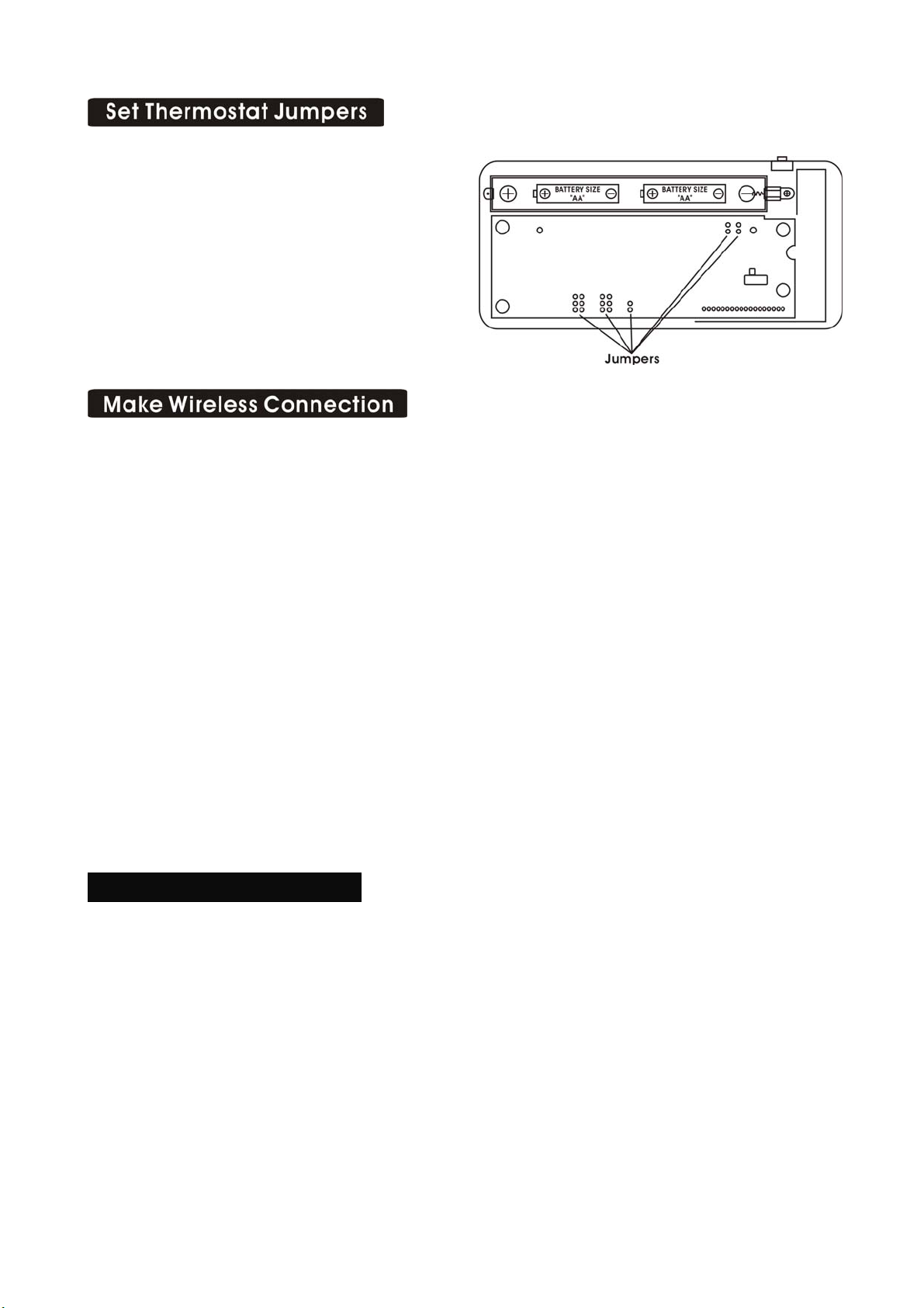
Remove the unit from back cover to configure
the Thermostat.
Refer to the step-by-step wiring diagram you
used to wire the Wall Unit. There you will find
a jumper setting diagram for the unit
(pages 10 through page 16).
Push RESET on the Thermostat (anytime set
up jumpers are changed, reset is required)
After you have finished the wiring of the WALL UNIT unit and the set the JUMPERs of the unit,
the two units must be radio connected before they can be used. If the BINDING radio z-wave icon
on the display is blinking, they are connected; if it is NOT ON follow this procedure connect them.
On the i29 Master thermostat. (WALL UIIT)
Push and Hold the binding button.
Touch the reset button once.
Release the binding button.
On the Slave Thermostat. (You can be purchased it at Home Depot).
Push and Hold the binding button.
Touch the reset button once.
When the radio z-wave icon is blinking on screen, release the binding button.
The above procedures clears the two radios so they can now be connected by doing the following:
Push the reset button once.
The radio z-wave icon is goes off.
The Z-Wave radio system
There have been many radio controlled thermostat systems but they were one way and there was no
indication if they were working. The new Z-Wave radio is two way, it sends the command and gets
back confirmation that the command was received and implemented.
There is a radio z-wave icon on the Thermostat lower right display. If this icon is not there,
communication has been lost. If this occurs, all HVAC functions are shut off.
Though the units are designed to work at least 100 feet from each other that distance can be affected
by interference or blocking from walls etc. If your i29 Thermostat unit cannot stay in
communication (the radio z-wave icon does not stay on) you may need a repeater unit between the
two which can be purchased at home depot.
7
Page 8

The radio z-wave icon also shows a radiation pattern every time the Slave Thermostat
communicates with the WALL UNIT unit.
Once the two units are connected, follow these procedures to verify you have correctly installed the
Thermostat and its WALL UNIT unit.
Because of the radio communication confirmation system, there will be a small delay between the
operation and the function. Follow these procedures to verify you have correctly installed the i29
system.
To check Fan: (If you connected the G wire – fan relay)
Switch the FAN switch to the ON position. You should see the FAN light go ON on the Wall
Unit and verify that air is blowing from the system. Return to AUTO position for normal
operation.
To check HEAT mode:
Press the mode button to HEAT.
Set the fan switch to AUTO.
·Using the TEMP + button raise the Target T emp to 90deg.
Allow the system 2 min to respond.
Verify that heat is blowing from the system. HEAT light on the Wall Unit should go ON.
To check COOL mode:
Press the mode button to COOL.
Press the TEMP – button to a temp 5 degrees below the room temp.
Allow the system 2 minutes to respond.
Verify that cool air is blowing from the system. COOL light on the Wall Unit should go ON.
NOTE: If you have labeled your wires, follow the correct Step-By-Step, and these Check
procedures do not operate you system call support at 1-877-505-2353
Congratulations, you have successfully installed your unit. Please proceed to the
OPERATING Guide to initialize the i29 System.
8
Page 9

NOTE: The Thermostat comes from the factory calibrated to +/-1。of actual temperature. It is an
accurate instrument. If you want your thermostat to display the same temperature as another
thermometer in your home, you can adjust its calibration.
To change the calibration:
Remove the i29 Thermostat from back cover.
Locate the calibration switch and slide it to the ON
position. The current calibration factor (+/-) of the
Thermostat will appear in the LCD display.
Push the UP or DOWN arrows until the desired calibration
factor is reached.
Slide the Calibration switch to the OFF position. The new calibrated
temperature will be displayed on the LCD.
9
Page 10

2 Stage Heat and Cool
STEP 1 – Connect the W wire to the W terminal and W2 to W2 on the Wall Unit. This connects 2
stages of heat.
STEP2 – Connect the Y wire to the Y terminal on the Wall Unit. This connects 1 stages of cool.
STEP3 – Connect the RH or R wire to the RH terminal on the thermostat. This connects the
Heater/Cooler Power.
STEP4 – Connect the G wire to the G terminal on the Thermostat. This connects to the Fan.
STEP5 – C wire to the C on the Wall Unit for 24vac power.
STEP6 – Set Config jumpers per this diagram. If you have Electric heat remove GAS jumper to
ELECT
Your HVAC system is now connected to the Wall Unit.
Please Go To Page 6
GAS NORMAL RC-RH OFF ℉ HP-AUX ELECT
10
Page 11

2 Wire Heat Heating GAS MILLIVOLT or 24vac
STEP 1 – Connect the R (or RH) wire to the RH terminal on the Wall Unit. This connects the
Heater Power to the Wall Unit.
STEP2 – Connect the W wire to the W on the Wall Unit. This connects the heater control line to
the i29 system.
STEP3 – C wire to the C on the Wall Unit for 24vac power.
NOTE: For gas millivolt system, a 24VAC wall adapter must be connected to the RH and
C terminals to power the WALL UNIT
STEP4 – Set Config jumpers per this diagram. If you have Electric heat remove GAS jumper to
ELECT.
Your Heater is now connected to the Wall Unit.
Please Go To Page 6
GAS NORMAL RC-RH OFF ℉ HP-AUX ELECT
11
Page 12

3 Wire Heat
STEP 1 –Connect the R (or RH) wire to the RH terminal on the Wall Unit. This connects to the
Heater Power.
STEP2 –Connect the W wire to the W terminal on the Wall Unit. This connects the heater control
line to the i29 system.
STEP3 – Connect the G wire to the G terminal on the Thermostat. This connects the Fan to the
Wall Unit.
STEP4 – C wire to the C on the Wall Unit for 24vac power.
STEP5 – Set Config jumpers per this diagram. If you have Electric heat remove Gas jumper to
Elect.
Your system is now connected to the Wall Unit.
Please Go To Page 6
GAS NORMAL RC-RH OFF ℉ HP-AUX ELECT
12
Page 13

4 Wire Heat/Cool
STEP 1 – Connect the W wire to the W terminal on the thermostat. This connects to the heater
control line.
STEP2 – Connect the Y wire to the Y terminal on the Wall Unit. This connects to the Cooler
compressor.
STEP3 – Connect the RH or R wire to the RH terminal on the thermostat. This connects the
Heater/Cooler Power.
STEP4 – Connect the G wire to the G terminal on the Thermostat. This connects to the Fan.
STEP5 – C wire to the C on the Wall Unit for 24vac power.
STEP6 – Set Config jumpers per this diagram. If you have Electric heat remove GAS jumper to
ELECT.
Your HVAC system is now connected to the Wall Unit.
Please Go To Page 6
GAS NORMAL RC-RH OFF ℉ HP-AUX ELECT
13
Page 14

5 Wire Heat/Cool
STEP 1 – Connect the W wire to the W terminal on the thermostat. This connects to the heater
control line.
STEP2 – Connect the Y wire to the Y terminal on the Wall Unit. This connects to the Cooler
compressor.
STEP3 – Connect the RH wire to the RH terminal and the RC wire to the RC terminal on the Wall
Unit. This connects the Heater/Cooler Power.
STEP4 – Connect the G wire to the G terminal on the Thermostat. This connects to the Fan.
STEP5 – C wire to the C on the Wall Unit for 24vac power.
STEP6 – Remove the RH/RC jumper on the Wall Unit.
STEP7 – Set Config jumpers per this diagram. If you have Electric heat remove GAS jumper to
ELECT.
Your HVAC system is now connected to the Wall Unit.
Please Go To Page 6
GAS NORMAL RC-RH OFF ℉ HP-AUX ELECT
14
Page 15

4 Wire Heat Pump w/o Aux
STEP 1 – Connect the O wire to the O terminal or B wire to the B terminal on the Wall Unit. (If
you have both O and B – connect O wire to O terminal. DO NOT connect B to B
terminal – see pg 17 Trane for B wire terminal) This connects the change-over valve.
STEP2 – Connect the Y wire to the Y on the Wall Unit. This connects the Compressor.
STEP3 – Connect the R wire to RH on the Wall Unit. This connects to the 24vac power.
STEP4 – Connect the G wire to the G terminal on the Wall Unit. This connects the Fan.
STEP5 – C wire to the C on the Wall Unit for 24vac power.
STEP6 – Set Config jumpers per this diagram.
Your HVAC system is now connected to the Wall Unit.
Please Go To Page 6
ELECT HEAT PUMP RC-RH OFF ℉ HP-AUX ELECT
15
Page 16

5 Wire Heat Pump w/ Aux Heat
STEP 1 – Connect O wire to the O terminal or B wire to the B terminal on the Wall Unit. (If you
have both O and B – connect O wire to O terminal. DO NOT connect B to B terminal –
see pg 17 Trane for B wire terminal)
STEP2 – Connect the W2 wire to W2 on the Wall Unit.
STEP3 – Connect the Y wire to Y on the Wall Unit.
STEP4 – Connect the R wire to RH on the Wall Unit.
STEP5 – Connect the G wire to G on the Wall Unit.
STEP6 – C wire to the C on the Wall Unit for 24vac power.
STEP7 – Set Config jumpers per this diagram. Remove HP-AUX ELECT jumper to FOSSIL for
Gas or Oil aux heat.
Your HVAC system is now connected to the Wall Unit.
Please Go To Page 6
ELECT HEAT PUMP RC-RH OFF ℉ HP-AUX ELECT
16
Page 17

The i29 Thermostat can be used with most 24 volt gas, oil or electric heating and air conditioning
systems, heat pumps or gas millivolt heating systems. It cannot be used with 120 volt heating
systems. Ask The Home Depot for other thermostats to control those systems.
The i29 Thermostat is digital. You can set your desired heat and cool temperature set point directly
on the Large LCD display. You can easily override the set temperatures.
4-minute minimum off time in COOL protects your air conditioning system from being damaged.
Your Wires Ritetemp Terminal
R or V or VR RH and RC Single power for HEAT and COOL
RH or 4 RH Power for HEAT (RH not connected to RC)
RC RC Power for COOL (RH NOT connected to RC)
W W Heat control
W2 W2 2nd stage HEAT or heat pump auxiliary heat
? A 3rd wire for zoned hot water heat (see zoned)
Y Y COOL control
G or F G FAN control
C or X C Common 24VAC power (to power thermostat)
E Emergency heat (do not connect, tape off)
L System monitor (do not connect, tape off)
T Outdoor sensor (do not connect, tape off)
B or B Heat pump changeover (cool to heat, powered in heat)
O O Heat pump changeover (heat to cool, powered in cool)
B and O SEE NOTE
B and O
NOTE: If there are both B and O wires (Trane pump products). DO
NOT CONNECT B to B terminal, connect B to C terminal.
17
Page 18

Zoned Systems
Your Wires Ritetimp Terminal
Lennox Heat Pump
V or VR or R RH
M or Y Y
Y or W or W2 W2
F or G G
R or O O
X or X2 or C C
Trane Products [American Standard]
B C
W or W1 W2
Your Wires Ritetemp Terminal
2 wire Zoned Hot Water
R RH
W W
3 Wire Zoned Hot Water
Motor Driven Valves
R RH
W W
Y (the 3rd wire) A
3 Wire Zoned Hot Water
Solenoid valves
R RH
W A
Y (the 3rd wire) W
Configuration jumpers allow your i29 Thermostat to be adapted to many different HVAC control
applications.
RESET UNIT
AFTER JUMPER CHANGE
18
Page 19

Jumper Open = NO FAN
Upper Jumper Closed = ELECT
Lower Jumper Closed = GAS
Jumper Open = NORMAL
Upper Jumper Closed = AUX HEAT ONLY
Lower Jumper Closed = HEAT PUMP
Jumper Open = RC – RH SEPARATE
Jumper Closed = RC - RH CONNECTED
Jumper Open = ℉ (FAHRENHEIT)
Jumper Closed = ℃ (CENTIGRADE)
Jumper Open = HP – AUX, ELECT
Jumper Closed = HP – AUX, FOSSIL
19
Page 20

Customer Support: 877-505-2353 or
Visit our website www.ritetemp-thermostats.com
Printed in China
20
Page 21

Operation guide i29 rev.5
Statement of use: The i29 Thermostat can be used with millivolt, 24VAC, 1 and 2
stage conventional gas/oil/elect heat, 1 and 2 stage heat pumps, 2 or 3 wire zoned hot
water, zoned forced air, 1 stage cooling and hybrid systems.
It cannot be used with 120 volt heating systems.
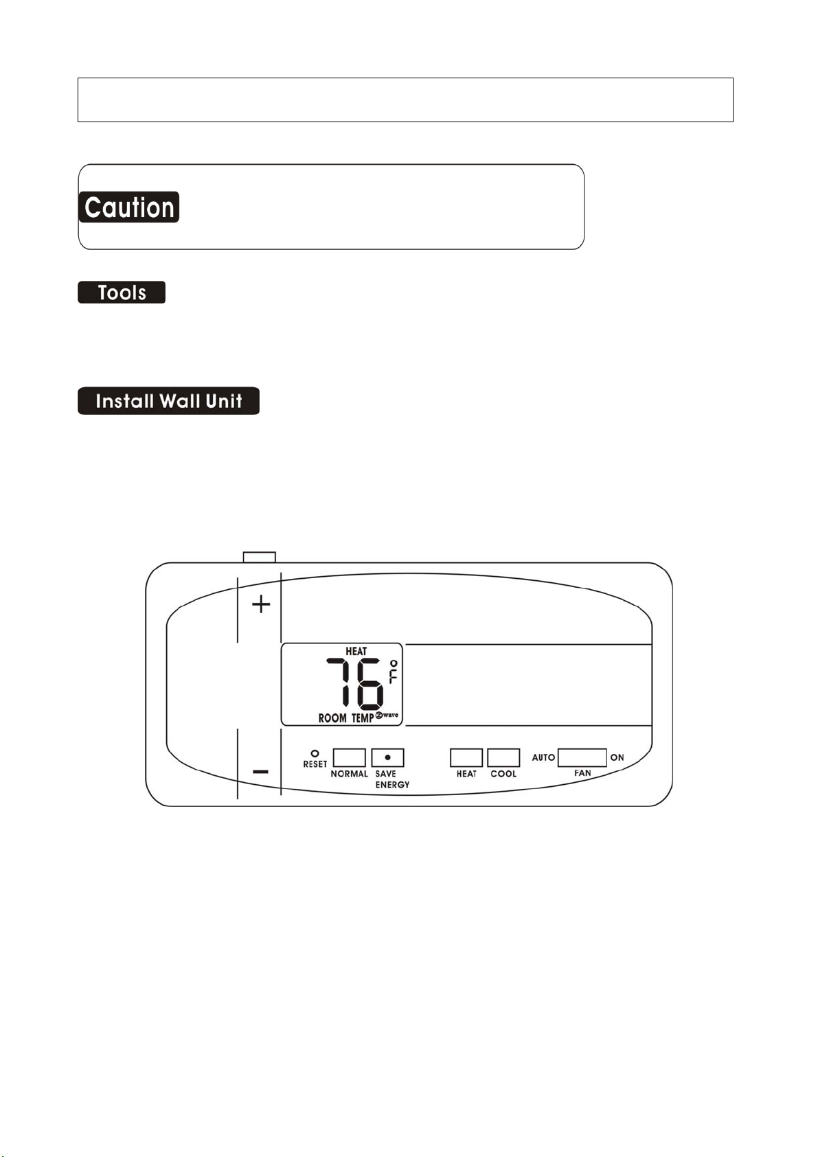
Current Temperature SET Temperature
Display Display
1
Page 22

Location
The Thermostat should be located in a convenient location in the living area. It is
important to keep the thermostat away from HVAC registers, windows, direct sun, or
a breezy areas.
Do not hold the Thermostat for long period as your hands, this will heat it and change
the displayed room temperature. If this occurs it may take 20 minutes to re-stabilize to
the actual room temperature.
Configure
Set HEAT/COOL mode buttons to HEAT or COOL. The unit will display the Room
temperature. Set the Fan switch to AUTO.
Operate
Press the TEMP UP and TEMP DOWN buttons on the Thermostat to select the
desired temperature. The TARGET icon will be displayed with your desired
temperature. (Display will return to room temp in 5 sec).
In the winter, set the system button to HEAT to control your heating system.
In the summer, set the system button to COOL to control your AC.
In spring and fall or when windows are open, you can set the system button to OFF.
Setting the FAN switch to AUTO automatically runs your system’s fan during heating
and cooling.
Setting the FAN switch to ON runs your system’s fan continuously even without
heating and cooling.
Save Energy Buttons
The NORMAL/SAVE ENERGY buttons allows you to set a comfort target
temperature (NORMAL) and an offset target temperature (SAVE ENERGY)
temperature. The defaults for heat targets are: NORMAL 70F, SAVE ENERGY 65F.
The defaults for cool targets are: NORMAL 75F, SAVE ENERGY 80F. However,
these 4 target temperature can be set to your preference by using the +/- buttons. The
2
Page 23

save energy position could be used when you are going to work, going to bed, on
b
vacation, etc.
Setting the FAN switch to AUTO automatically runs your system’s fan during heating
and cooling. Setting the FAN switch to ON runs the systems fan continuously.
The Thermostat should not be held for very long as the heat from your hands will heat
up the i29 Thermostat and eventually change the displayed room temperature. If this
occurs the HVAC system will act on this incorrect temp reading causing unreliable
results.
Wall Unit Operation- Master Thermostat
The Wall Unit has a 4 minutes delay for compressor protection in HEAT PUMP or
COOL. This protects the compressor from to frequent cycling.
The Z-Wave radio system
The new Z-Wave radio is two way, it sends the command and gets back confirmation
that the command was received and implemented.
There is a radio z-wave icon on the i29 thermostat lower right display. If this icon is
not there, communication has been lost. If this occurs, all HVAC functions are shut off.
The radio z-wave icon also shows a radiation pattern every time the Z-Wave products
Thermostat “Slave Thermostat” (you can be purchased it at Home Depot)
communicates with i29.
Thought the units are designed to work at least 100 feet from each other that distance
can be affected by interference or blocking from wall etc. If your i29 Thermostat unit
cannot stay in communication (The radio z-wave icon does not stay on) you may need
a repeater unit between the two which can be purchased at Home Depot.
Low Battery
LOW BATTERY Thermostat – When the batteries are low on the Thermostat, the
attery icon will flash. Remove the Wall Unit and replace the two AA batteries first.
3
Page 24

/ ℃ Select
The F/C jumper is under the top cover. It determines which temperature system is
displayed on the LCD display. With the jumper off, the display is Fahrenheit (default).
With the jumper on both pins, the display is Centigrade. When this jumper is changed,
the unit must be reset (on the top cover).
To set a Heat Pump’s Aux only mode
If you have a heat pump with auxiliary heat, and the heat pump is not working, you
can use just the aux heat. To do this, change the mode button to OFF. Now switch to
aux heat by moving the Heat Type jumper from heat pump to aux heat only. Press
mode button back to HEAT.
NOTE: As soon as the heat pump is again working, press mode button to OFF and
change the Heat Type jumper from aux heat only back to heat pump as aux heat is
more expensive than heat pump.
4
Page 25

FCC Information
This equipment has been tested and found to comply with the limits for a Class B
digital device, pursuant to Part 15 of the FCC Rules. These limits are designed to
provide reasonable protection against harmful interference in a residential installation.
This equipment generates, uses and can radiate radio frequency energy and, if not
installed and used in accordance with the instructions, may cause harmful interference
to radio communications. However, this is no guarantee that interference will not
occur in a particular installation. If this equipment does cause harmful interference to
radio or television reception, which can be determined by turning the equipment off
and on, the user is encouraged to try to correct the interference by one or more of the
following measures:
- Reorient or relocate the receiving antenna.
- Increase the separation between the equipment and receiver.
- Connect the equipment into an outlet on a circuit difference from that to which the
receiver is connected.
- Consult the dealer or an experienced radio/TV technician for help.
Warning: Changes or modifications to this equipment not expressly
approved by the party responsible for compliance could void the
user’s authority to operate the equipment.
Customer Support 877-505-2353 Visit our website
www.ritetemp-thermostats.com
5
 Loading...