

Page 1

MPA-50 40-Watt PA Amplifier
32-2002.fm Page 1 Friday, February 11, 2000 11:36 AM
Owner’s Manual
Please read before using this equipment.
Page 2

32-2002.fm Page 2 Friday, February 11, 2000 11:36 AM
ˆ
Contents
Features ................................................................................................................... 3
Preparation .............................................................................................................. 4
Presetting the Controls ....................................................................................... 4
Choosing a Location .................... .... ... ....................................... ... ...................... 4
Placing the Speakers .......................................................................................... 4
Making Connections ............................................................................................... 5
Speakers .................................................................................................................. 6
Speaker Phasing ................................................................................................ 6
Determining Total Speaker Impedance .............................................................. 6
Connecting Speakers .................. .... ... ... ... ....................................... ... .... ... ......... 7
One Speaker ................................................................................................ 8
Two or More Speakers Without Transformers .......... ................................... 8
Multiple Speakers with Transformers ......................................................... 10
Controls and Operation ........................................................................................ 12
Troubleshooting .................................................................................................... 13
Care ........................................................................................................................ 14
Replacing the Fuse ............. ... ... ... .... ...................................... .... ....................... 14
Specifications .......................... .......................... ...................... ....................... ....... 15
2000 Tandy Corporation.
©
RadioShack and RadioShack.com are trademarks used by Tandy Corporation.
All Rights Reserved.
2
Page 3
32-2002.fm Page 3 Friday, February 11, 2000 11:36 AM
ˆ
Features
Your RadioShack MPA-50 40-Watt PA
Amplifier gives you 40 watts of solid
power for your public address (PA) system. The built-in three-band equalizer
enables you to tailor the sound to fit your
environment. Its wide frequency response easily handles amplification of
voice and music.
Its other features include:
Built-In Mixer and Preamplifier — pro-
duce the best output possible, even with
low-level audio input.
Microphone Jacks — let you connect
up to two high- or low-impedance microphones.
Input Jacks — let you connect auxiliary
equipment, such as a CD player, tape
deck, or receiver, for music and special
effects.
Spring-Loaded Terminals — make
speaker connection easy.
Your amplifier is ETL listed to UL standards and meets all applicable FCC
standards.
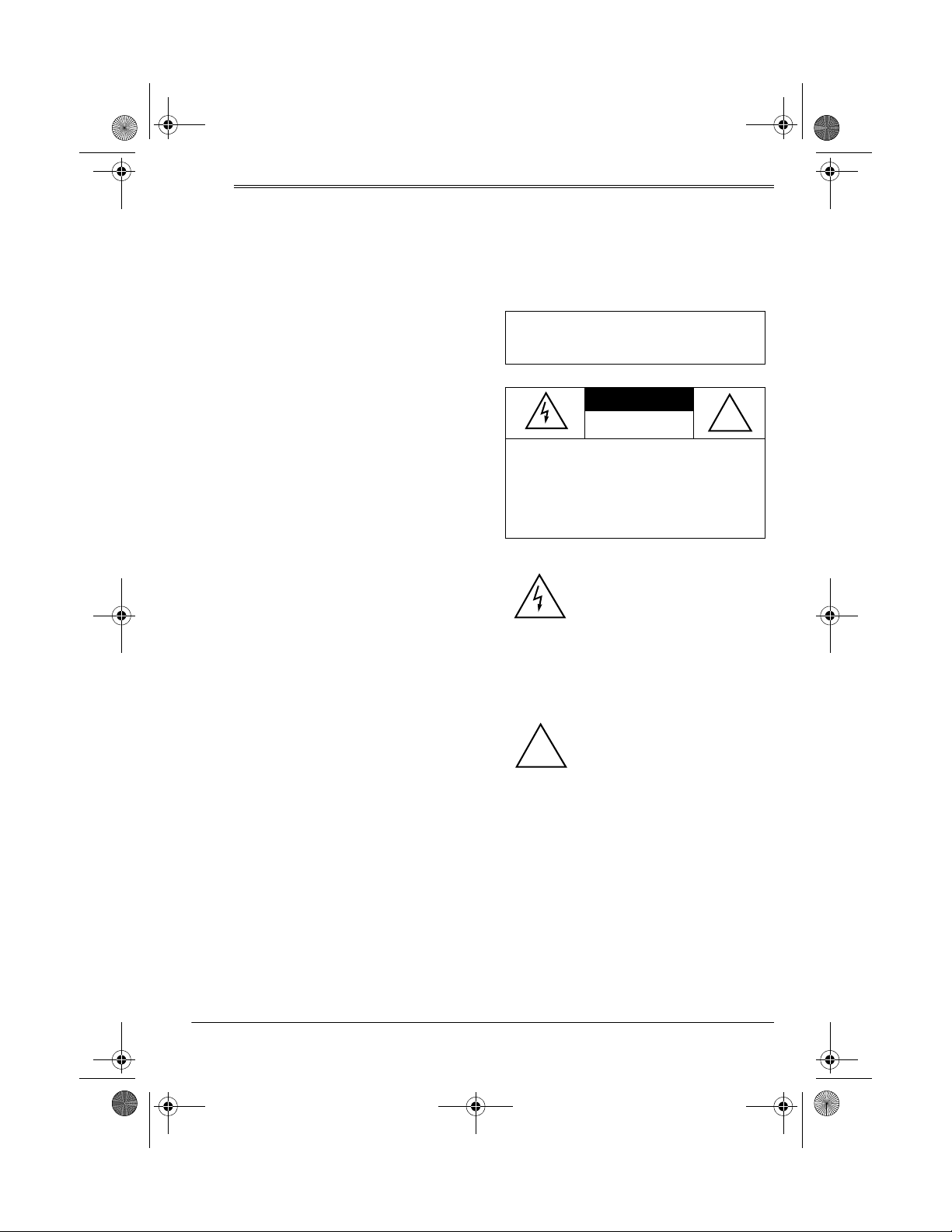
WARNING:
shock hazard, do not expose this product to
rain or moisture.
CAUTION:
OF ELECTRIC SHOCK, DO NOT
REMOVE COVER OR BACK. NO USERSERVICEABLE PARTS INSIDE. REFER
SERVICING TO QUALIFIED PERSONNEL.
To reduce the risk of fire or
CAUTION
RISK OF ELECTRIC
SHOCK. DO NOT OPEN.
TO REDUCE THE RISK
This symbol is intended to
alert you to the presence of
uninsulated dangerous voltage
within the product’s enclosure
that might be of sufficient magnitude to constitute a risk of
electric shock. Do not open
the product’s case.
!
Master Volume Control — lets you ad-
just the overall sound level.
Individual Microphone Controls — let
you separately adjust the volume of
each microphone.
Auxiliary Volume Control — lets you
adjust the volume of the connected
equipment.
Priority Terminals — let you connect
an optional switch to cut out all other audio input sources and give priority to
only the
MICROPHONE 1
input.
This symbol is intended to
inform you that important oper-
!
ating and maintenance instructions are included in the
literature accompanying this
product.
3Features
Page 4

32-2002.fm Page 4 Friday, February 11, 2000 11:36 AM
ˆ
Preparation
PRESETTING THE
CONTROLS
Warning:
amplifier could damage your hearing or
the speakers connected to the amplifier’s output.
To avoid accidentally overdriving a
channel or prematurely amplifying an
audio input, set all the amplifier’s frontpanel controls to their lowest settings.
To avoid sudden audio from the input
sources, be sure all audio devices are
turned off before you connect them to
the amplifier.
A sudden high output from the
CHOOSING A LOCATION
Choose a location with adequate ventilation. Do not place the amplifier on thick
carpeting or cushions (which can restrict
the air flow) or near a heat so urce, such
as a heat vent or radiator (which can
cause the amplifier to overheat).
Notes:
• Place the speakers so they are
mounted slightly above the listeners’
heads and pointed toward them.
• When using more than one speaker,
overlap the projection areas of the
speakers to prevent “dead” spots.
PLACING THE SPEAKERS
Speaker placement depends on your
room’s size and arrangement. We recommend you play a wide-range recording and experiment with speaker
placement until you find the locations
that result in the best sound.
4
Preparation
Page 5
32-2002.fm Page 5 Friday, February 11, 2000 11:36 AM
ˆ
Making Connections
Important: Connect all auxiliary equipment and speakers before connecting power.
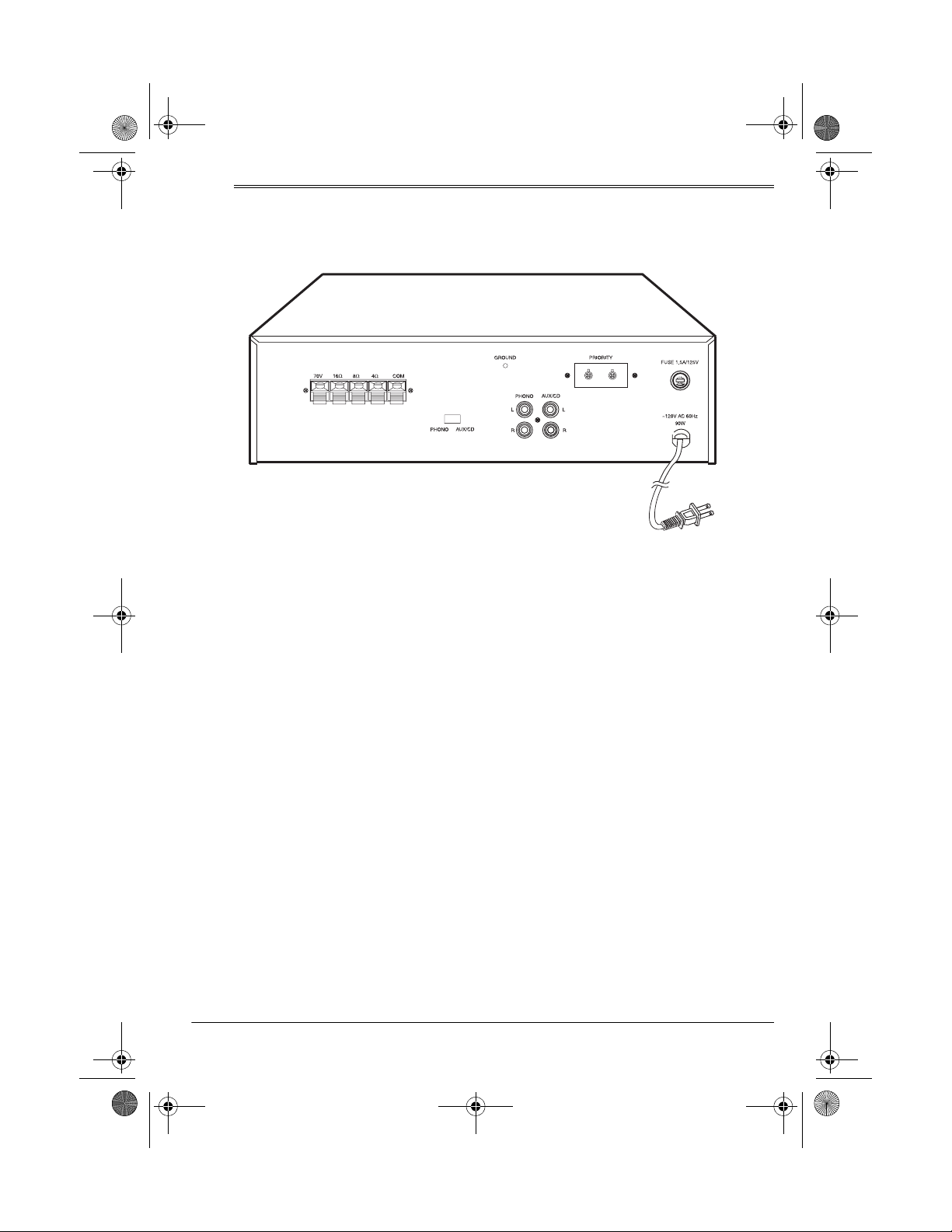
PHONO L (Left) and R (Right) Input
Jacks — Connect a turntable with a
magnetic cartridge. To avoid distortion,
do not connect a high-level audio input
source to these jacks. Even though the
amplifier has
output from the amplifier is monaural.
AUX/CD L and R Input Jacks — Connect any high-level sound source (such
as a tape deck, CD player, receiver, or a
turntable with a ceramic or crystal cartridge). To connect a stereo source, use
shielded audio cable (available at your
local RadioShack store); however, the
amplifier’s output is monaural.
GROUND Screw — Connect the
ground wire (usually black or green)
from your turntable to this screw to avoid
a low-frequency hum. You can also use
this screw to ground any other system
connection.
and R input jacks, the
L
PHONO/AUX/CD Switch — Select the
input source. Even if you connected
auxiliary equipment to both the
and
AUX/CD
only one source at a time.
Speaker Push Terminals — Press the
appropriate tab to open a terminal. Insert the end of a speaker wire into the
opening, then release the tab to close
the terminal and secure the wire (see
“Connecting Speakers” on Page 7).
PRIORITY Terminals — To allow
CROPHONE 1
connect an SPST (single-pole, singlethrow) switch to the amplifier’s
terminals using normal two-conductor
wire (switches and wire are available at
your local RadioShack store). Refer to
the switch’s manual for connection a nd
usage instructions.
AC Power Cord — To use AC power,
plug this cord into an AC outlet.
input jacks, you can use
to override all other inputs,
PHONO
MI-
PRIORITY
5Making Connections
Page 6

32-2002.fm Page 6 Friday, February 11, 2000 11:36 AM
ˆ
Speakers
SPEAKER PHASING
Phasing is the direction the speaker
cone moves with reference to the pola rity of the connection wires. Proper phasing is important when you use more than
one speaker in the same room or area.
Out-of-phase speakers can lose up to
one-half of their potential volume, and
can have a significantly decreased bass
effect.
Speakers are in phase if all the speaker
cones move in the same direction when
an equal signal is applied. Phasing is
correct if you observe the correct polarity (+ to + and – to –) when connecting
the speakers.
Most speaker terminals are color-coded
or have a mark that indicates the terminal’s polarity. Usually, terminals with
positive polarity are red or have a plus
symbol (+), and terminals with negative
polarity are black or have a minu s symbol (–). If the speaker terminals ar e unmarked, follow these steps to determine
their polarity.
minal that does not have the wire
attached to it.
4. Touch the negative end of the battery with the lose end of the wire
attached to the other speaker terminal. Note the direction of the cone
movement — inward or outward.
5. If the speaker cone moves outward,
the speaker terminal where you
touched the positive end of the battery is positive. Mark that terminal
with a + and mark the other terminal
with a –.
If the speaker cone moves inward,
the speaker terminal with the wire
attached that touched the negative
end of the battery is positive. Mark
that terminal with a + and m ark the
other terminal with a –.
6. Remove the wire.
Repeat Steps 2–6 for each speaker with
unmarked terminals you plan to connect
to the amplifier.
1. Remove about 1 inch of insulation
from both ends of a short piece of
wire (available at your local
RadioShack store). Then twist the
exposed wire to secure all its
strands.
2. Connect one end of the wire to one
of the speaker terminals.
3. Touch the positive end of a 1.5-volt
flashlight battery to the speaker ter-
6
Speakers
DETERMINING TOTAL
SPEAKER IMPEDANCE
Caution:
that is higher than 16 ohms (Ω) or lower
than 4 ohms can damage your amplifier
or speakers. Be sure to make the proper
connections.
Before you connect speakers to the amplifier, you must determine the total
speaker impedance. In determining the
total speaker impedance, you must first
A total speaker impedance
Page 7

32-2002.fm Page 7 Friday, February 11, 2000 11:36 AM
determine if your speakers are connected in series, parallel, or series/parallel
combined.
Note: We recommend that you use
speakers that are rated the same (for
example, all 8-ohm speakers) for a ll series or parallel connections.
• Speakers are connected in series
when the first speaker’s positive terminal is connected to the next
speaker’s negative terminal. Determine the total impedance of speakers connected in series by adding
up the individual impedances of all
the connected speakers.
For example, if you want to connect
two 8-ohm speakers in series, add 8
(the impedance of one speaker)
plus 8 (the impedance of the other
speaker) for a total speaker impedance of 16 ohms.
• Speakers are connected in parallel
when all their negative terminals are
connected together and all their
positive terminals are connected
together. For speakers rated the
same, find the total impedance of
speakers connected in parallel by
dividing the impedance of one
speaker by the number of speakers.
For example, if you want to connect
two 8-ohm speakers in parallel,
divide 8 (the impedance of one
speaker) by 2 (the number of speakers) for a total speaker impedance
of 4 ohms.
• If you connect more than two speakers using only series or only parallel
connections, the total impedance
might exceed the amplifier’s maxi-
mum impedance (16 ohms) or fall
below its minimum impedance (4
ohms).
For example, if you connect four 8ohm speakers:
–In series, the total impedance is 3 2
ohms (8 + 8 + 8 + 8 = 32). This
exceeds the maximum rating.
–In parallel, the total impedance is 2
ohms (8 ÷ 4 = 2). This falls below
the minimum rating.
You can arrive at a proper total
impedance by combining series and
parallel connections.
CONNECTING SPEAKERS
You need speakers and wire (available
at your local RadioShack store) to complete the connections to your amplifier.
Be sure to use 16-gauge wire or heavier. (The smaller the gauge number, the
heavier the wire.)
Remove about 1 inch of insulation from
both ends of each wire. Then twist the
exposed wire to secure all its strands.
Connect the speaker wire to the amplifier by pressing down on the appropriate
push terminal tab and inserting the end
of the twisted wire into the terminal’s
hole. Then release the tab to secure the
wire.
You can connect one or more 4-, 8-, or
16-ohm speakers, with or without transformers, between the amplifier’s output
and the speakers’ input. To ensure
equal volume from each speaker, all the
connected speakers should have the
same impedance rating.
7Speakers
Page 8
32-2002.fm Page 8 Friday, February 11, 2000 11:36 AM
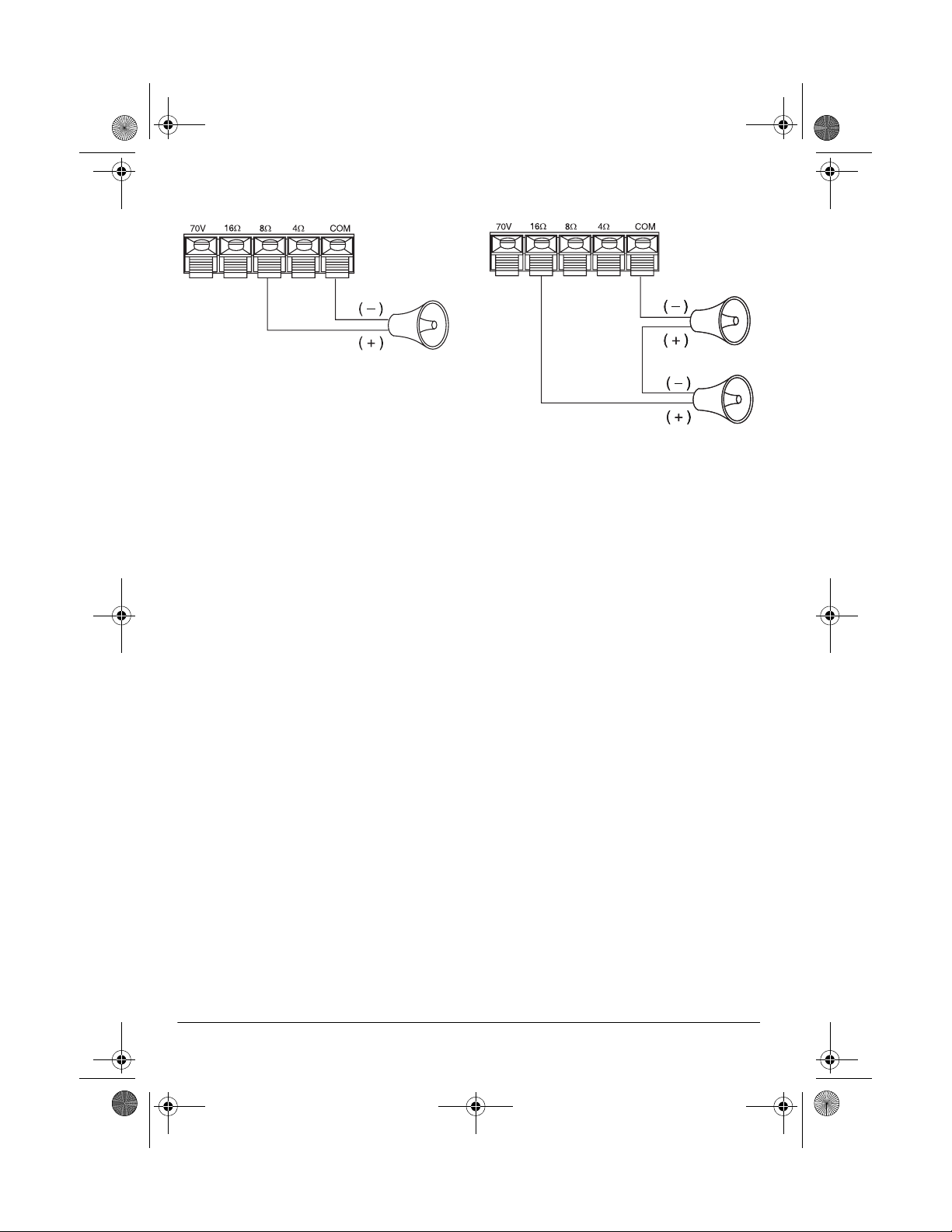
One Speaker
8
Speaker
ΩΩΩΩ
Connect the speaker’s negative (–) terminal to the amplifier’s
COM
(common)
terminal. Then connect the speaker’s
positive (+) terminal to the amplifier’s
terminal that matches the speaker’s impedance. For example, if you have an 8ohm speaker, connect the speaker’s
positive terminal to the amplifier’s 8-ohm
terminal.
Two or More Speakers Without
T ransformers
We recommend connections without
transformers if the length of the conn ecting wires between the amplifier and the
speakers is 50 feet or less.
Speakers in Series
Two 8
Speakers
ΩΩΩΩ
1. To determine the total impedance of
speakers connected in series, add
the impedance of all the speakers.
For example, if you want to connect
two 8-ohm speakers in series, add 8
(the impedance of one speaker)
plus 8 (the impedance of the other
speaker) for a total speaker impedance of 16 ohms.
2. Connect the first speaker’s positive
(+) terminal to the second speaker’s
negative (–) terminal.
When making connections without
transformers, all the speakers must
have the same impedance rating to ensure equal volume from each speaker.
When there is more than one speaker in
a sound system, you must determine the
total impedance of the speakers before
you can make the correct connection.
The total impedance of all the speakers
must match one of the amplifier’s output
4
8
terminals (
8
ΩΩΩΩ
,
ΩΩΩΩ
, or
16
ΩΩΩΩ
).
Speakers
3. Connect the first speaker’s negative (–) terminal to the amplifier’s
COM
terminal.
4. Connect the second speaker’s positive (+) terminal to the amplifier’s
terminal that matches the total
speaker impedance (
16
ΩΩΩΩ
, in this
example).
Page 9
32-2002.fm Page 9 Friday, February 11, 2000 11:36 AM
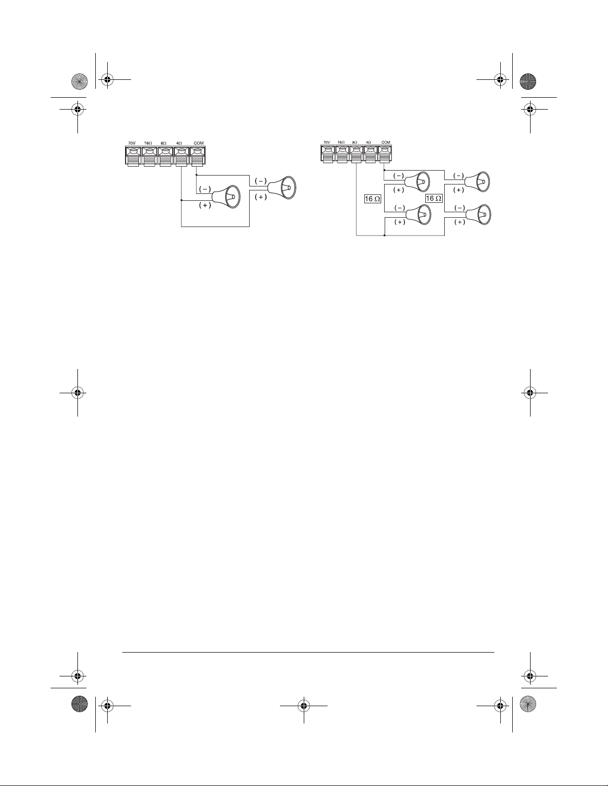
Speakers in Parallel
Two 8
Speakers
ΩΩΩΩ
1. To determine the total impedance of
speakers connected in parallel,
divide the impedance of one
speaker by the number of speakers.
For example, if you want to connect
two 8-ohm speakers in parallel,
divide 8 (the impedance of one
speaker) by 2 (the number of speakers) for a total speaker impedance
of 4 ohms.
2. Connect the speakers’ negative (–)
terminals together.
3. Connect the speakers’ positive (+)
terminals together.
4. Connect the speakers’ negative (–)
terminals to the amplifier’s
COM
ter-
minal.
5. Connect the speakers’ positive (+)
terminals to the amplifier’s terminal
that matches the total speaker
impedance (
ΩΩΩΩ
, in this example).
4
Series and Parallel Combined
Four 8
Speakers
ΩΩΩΩ
If you must hook up more than two
speakers, you might have to use a combination of series and parallel connections to get a total impedance that
matches one of the amplifier’s terminals.
If you connect four 8-ohm speakers in
series, the total impedance is 32 ohms
(8 + 8 + 8 + 8 = 32). This exceeds the
maximum rating.
If you connect these speakers in parallel, the total impedance is 2 ohms (8 ÷ 4
= 2). This falls below the minimum rating.
You can arrive at a proper total impedance by combining series and parallel
connections.
1. Group speakers into pairs.
2. Connect each pair of speakers in
series.
For example, the total impedance of
each pair of 8-ohm speakers is 16
ohms (8 + 8 = 16).
3. Connect the pairs of speakers in
parallel.
9Speakers
Page 10
32-2002.fm Page 10 Friday, February 11, 2000 11:36 AM
4. To determine the total impedance of
speakers connected in serial and
parallel combined, divide the impedance of one pair of speakers by the
number of pairs.
For example, if you want to connect
four 8-ohm speakers in serial and
parallel combined, divide 16 (the
impedance of one pair of speakers)
by 2 (the number of speaker pairs)
for a total speaker impedance of 8
ohms.
5. Connect the negative (–) terminals
of all pairs of speakers to the amplifier’s
COM terminal.
6. Connect the positive (+) terminals of
all pairs of speakers to the amplifier’s terminal that mat ches the total
speaker impedance (
8ΩΩΩΩ, in this
example).
Multiple Speakers with
Transformers
• You can add or remove a speaker
without having to recalculate the
entire system’s impedance.
• You can reduce signal loss when
you use speaker wire over 50 feet
long.
You need a separate transformer for
each speaker.
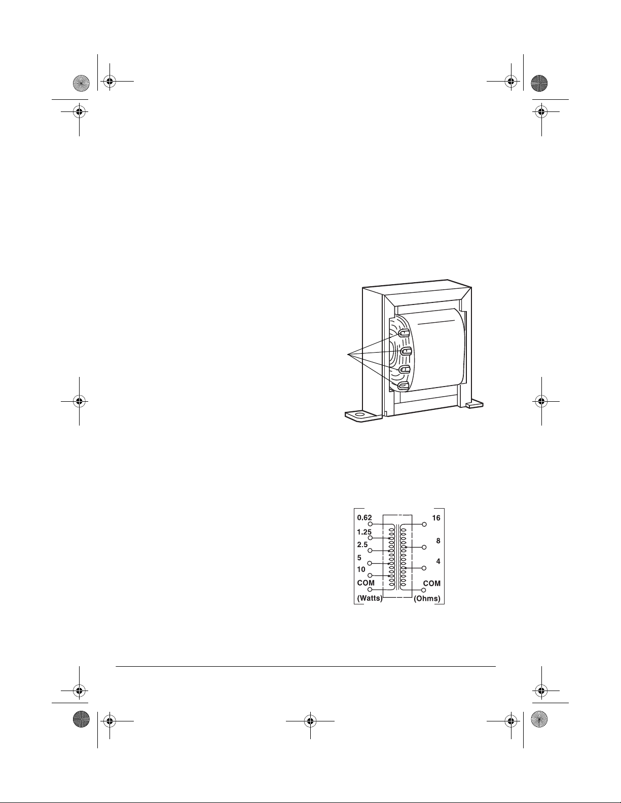
Line transformers have several connectors called taps.
Taps
For complex multiple-speaker arrangements that require many speakers and
long runs of connecting wire, we recommend you use a line transformer (not
supplied).
Note:
When running lengths of wire
longer than 50 feet, use wire that is
heavier than 16 gauge.
There are several advantages to using
transformers.
• You can connect speakers with different impedances without causing
differences in output between the
speakers.
10
Speakers
The primary taps (on one side of the
transformer) are the inputs and are ra ted
in watts. The secondary taps (on the opposite side of the transformer) are the
outputs and are rated in ohms.
Primary
Taps
Secondary
Taps
Page 11
32-2002.fm Page 11 Friday, February 11, 2000 11:36 AM
Cautions:
• Before you connect the speakers, be sure the total wattage of the primary taps
you intend to use does not exceed the amplifier’s maximum 40-watt ou tput power
rating.
• Avoid multiple connections to the amplifier’s
70V
and
COM
terminals.
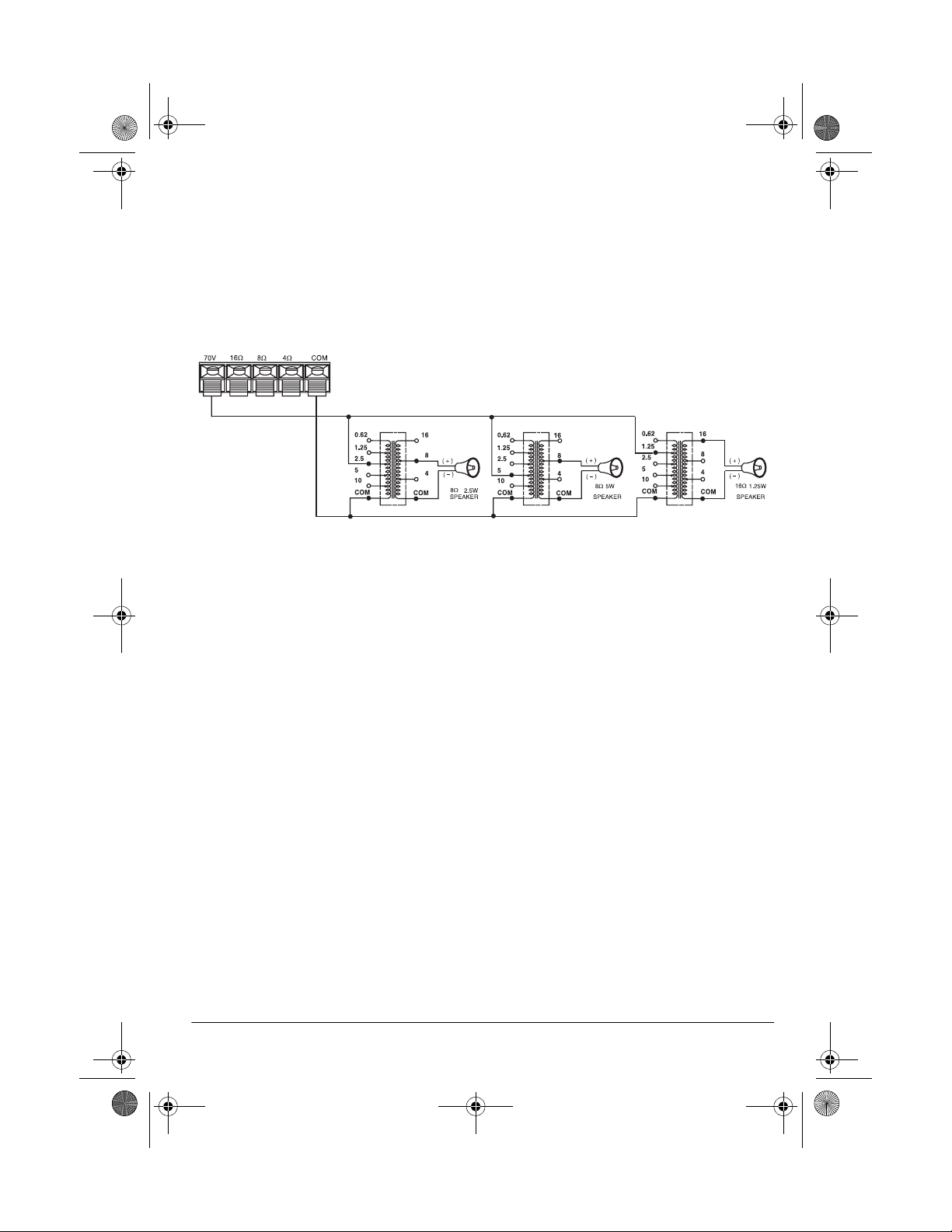
Follow these steps to make the connections.
1. Connect a wire from the amplifier’s
terminal to each transformer ’s primary
70V
tap that matches your speaker’s wattage rating. For example, if you will be connecting a 2.5-watt speaker to a transformer, connect this wire to the 2.5 tap on
that transformer’s primary side.
2. Connect a wire from the amplifier’s
terminal to the COM tap on each trans-
COM
former’s primary side.
3. Connect a wire from the speaker’s positive (+) terminal to each transformer’s
secondary tap that matches the speaker’s total impedance (4, 8, or 16 Ω). For
example, if you are connecting an 8-ohm speaker to a transformer, connect this
wire to the 8 tap on that transformer’s secondary side.
4. Connect a wire from the speaker’s negative (–) terminal to the COM tap on each
transformer’s secondary side.
11Speakers
Page 12
32-2002.fm Page 12 Friday, February 11, 2000 11:36 AM
ˆ
Controls and Operation
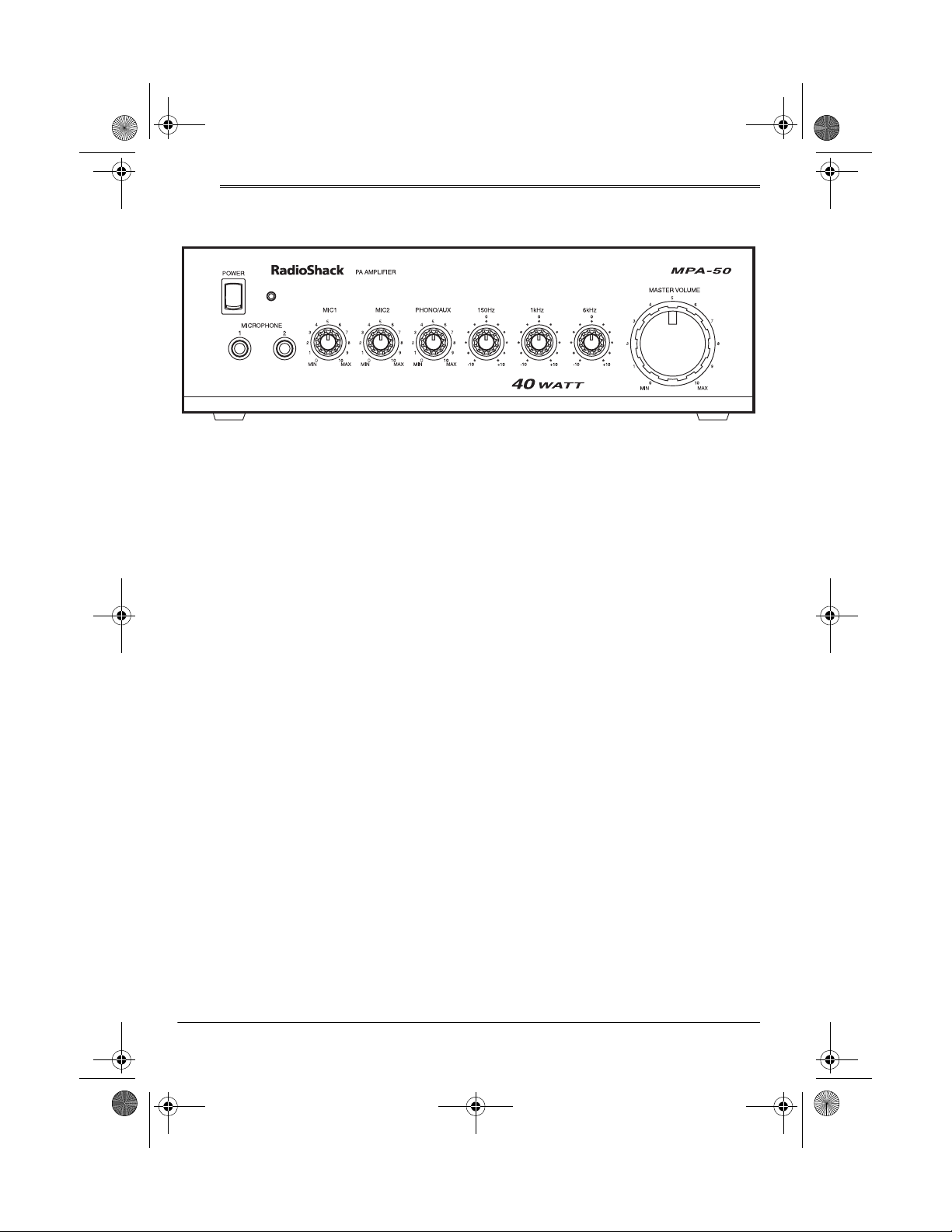
MICROPHONE 1 and 2 Inputs — Con-
nect any standard dynamic microphone
1
with a
POWER Switch and Indicator — Press
the bottom half of the switch to tu rn on
the amplifier. The indicator lights. Press
the top half of the switch to turn off the
amplifier. The indicator goes off.
MASTER VOLUME Control — Controls
the overall loudness level of all sources.
With the amplifier and the audio input
source turned on (and set to play, if
needed), set this control to its mid-range
setting (
adjusting the source mixing controls.
Caution: Do not raise the volume level
too high. Doing so might overload the
system.
MIC1 and MIC2 Source Mixing Controls — Adjust the input level for each
microphone to get the proper volume
and balance.
PHONO/AUX Source Mixing Control
— Adjusts the input level of the
or
volume and balance.
/4-inch plug.
). Adjust this control again after
5
AUX/CD
sound source for the best
PHONO
150Hz Equalizer Control — controls
output for instruments in this very low
range (such as an organ or a contrabassoon). Too much bass makes music
sound muddy and boomy, while too little
makes it sound hollow and thin. Rotate
the knob clockwise to enhance bass
sounds or counterclockwise to reduce
rumble, acoustic feedback, and other
low-frequency disturbances.
1kHz Equalizer Control — controls the
midrange frequencies (voice and instruments). Rotate the knob clockwise to
bring the vocalist “up front,” or counterclockwise to move the singer “back” into
the sound mix.
6kHz Equalizer Control — controls
high frequencies, such as those generated by cymbals, and can also act as a
high-frequency noise filter. Rotate the
knob clockwise to increase high frequencies, or counterclockwise if the
sound becomes overbearingly harsh
and strident.
12
Controls and Operation
Page 13

32-2002.fm Page 13 Friday, February 11, 2000 11:36 AM
ˆ
Troubleshooting
If you should run into difficulties, check
the wiring of the system. Are there any
short circuits in the speaker wiring?
Have you provided adequate ventilation? Did you calculate speaker impedance correctly?
Be sure microphones and connecting
cables are not defective.
Be sure you are using large enough
speaker wire. You should always use
16-gauge (or larger) wire. The l onger the
run of speaker wire, the heavier the
gauge should be.
If you have feedback problems, re position your microphones and speakers, or
adjust
ting.
MASTER VOLUME to a lower set-
If the amplifier does not work at all,
check the fuse on the rear panel. If it is
blown, replace it with one of the same
size and type (see “Replacing the Fuse”
on Page 14).
If you cannot solve the problem, contact
your local RadioShack store for assistance.
13Troubleshooting
Page 14

32-2002.fm Page 14 Friday, February 11, 2000 11:36 AM
ˆ
Care
To enjoy your MPA-50 40-Watt PA Amplifier for a long time:
• Keep the amplifier dry. If it gets wet,
wipe it dry immediately.
• Use and store the amplifier only in
normal temperature environments.
• Handle the amplifier gently and
carefully. Don’t drop it.
• Keep the amplifier away from dust
and dirt.
• Wipe the amplifier with a damp cloth
occasionally to keep it looking new.
Modifying or tampering with the amplifier’s internal components can cause a
malfunction and invalidate its warranty.
If your amplifier is not performing as it
should, take it to your local RadioShack
store for assistance.
REPLACING THE FUSE
terclockwise until the fuse holder
pops out.
3. Remove the fuse holder and replace
the fuse.
4. Slide the fuse holder back in place
then, using a flat-blade screwdriver,
push and turn the fuse holder’s cap
fully clockwise to secure it.
The power fuse protects your amplifier
from power (voltage or current) surges
when operating it from an AC power
source. If the POWER indicator does not
light when you press
fuse and replace it with one of the same
size and type. (A spare fuse is included.)
Follow these steps to replace the amplifier’s fuse.
1. Unplug the amplifier’s power cord.
2. Using a flat-blade screwdriver, push
and turn the fuse holder’s cap coun-
14
POWER
, check the
Care
Page 15

32-2002.fm Page 15 Friday, February 11, 2000 11:36 AM
ˆ
Specifications
Output Power at 1 kHz, 10% THD ............................................................................... 40 Watts
Power Bandwidth at 1W, 10% THD, Auxiliary Input ............................................ 70 Hz–20 kHz
THD at 2W, 1 kHz
MIC1 .............................................................................................................................. 1%
MIC2 .............................................................................................................................. 1%
AUX/CD ......................................................................................................................... 1%
PHONO ......................................................................................................................... 1%
Input Sensitivity at 10% THD, 1 kHz
MIC1 ........................................................................................................................ 2.5 mV
MIC2 ........................................................................................................................ 2.5 mV
AUX/CD .................................................................................................................. 150 mV
PHONO ................................................................................................................... 3.5 mV
Signal-to-Noise Ratio
MIC1 .......................................................................................................................... 65 dB
MIC2 .......................................................................................................................... 65 dB
AUX/CD ..................................................................................................................... 70 dB
PHONO ..................................................................................................................... 70 dB
Frequency Response at 8 Ohms, 2W
MIC1 ............................................................................................................. 70 Hz–20 kHz
MIC2 ............................................................................................................. 70 Hz–20 kHz
AUX/CD ........................................................................................................ 70 Hz–20 kHz
PHONO .............................................................................. 100 Hz/12 dB (10 kHz/–13 dB)
Equalizer Control Range at Each Band (Peak Point)
150Hz................. .......................................... .......................................... .................. ±12 dB
1kHz ........................................................................................................................ ±12 dB
6kHz ........................................................................................................................ ±12 dB
Crosstalk from AUX to PHONO ....................................................................... 40 dB (Nominal)
Hum and Noise at 8 Ohms
at Master Volume Minimum ....................................................................... 1 mV (Nominal)
at Master Volume Maximum .................................................................... 50 mV (Nominal)
Priority Terminals ............................................................................................... Normally Open
Power Requirement ........................................................................................... 120V AC 60 Hz
7
Dimensions (HWD) ......................................... 3
Weight ............................................................................................................ 9 lb 10 oz (4.4 kg)
/8 × 123/4 × 101/2 Inches (98 × 324 × 267 mm)
Specifications are typical; individual units might vary. Specifications are subject to change and
improvement without notice.
15Specifications
Page 16
32-2002.fm Page 16 Friday, February 11, 2000 11:36 AM
Limited One-Year Warranty
This product is warranted by RadioShack against manufacturing defects in material and workmanship under normal use for one (1) year from the date of purchase from Radi oSha ck company- owned
stores and authorized RadioShack franchisees and dealers. EXCEPT AS PROVIDED HEREIN, RadioShack MAKES NO EXPRESS WARRANTIES AND ANY IMPLIED WARRANTIES, INCLUDING
THOSE OF MERCHANTABILITY AND FITNESS FOR A PARTICULAR PURPOSE, ARE LIMITED
IN DURATION TO THE DURATION OF THE WRITTEN LIMITED WARRANTIES CONTAINED
HEREIN. EXCEPT AS PROVIDED HEREIN, RadioShack SHALL HAVE NO LIABILITY OR RESPONSIBILITY TO CUSTOMER OR ANY OTHER PERSON OR ENTITY WITH RESPECT T O ANY
LIABILITY, LOSS OR DAMAGE CAUSED DIRECTLY OR INDIRECTLY BY USE OR PERFORMANCE OF THE PRODUCT OR ARISING OUT OF ANY BREACH OF THIS WARRANTY, INCLUDING, BUT NOT LIMITED TO, ANY DAMAGES RESULTING FROM INCONVENIENCE, LOSS
OF TIME, DATA, PROPERTY, REVENUE, OR PROFIT OR ANY IND IRECT, SPECIAL, INCIDENTAL, OR CONSEQUENTIAL DAMAGES, EVEN IF RadioShack HAS BEEN ADVISED OF THE
POSSIBILITY OF SUCH DAMAGES.
Some states do not allow limitations on how long an implied warranty lasts or the exclusion or limit ation of incidental or consequential damages, so the above limitations or exclusions may not apply to
you.
In the event of a product defect during the warranty period, take the product and the RadioShack
sales receipt as proof of purchase date to any RadioShack store. RadioShack will, at its option, unless otherwise provided by law: (a) correct the defect by product repair without charge for parts and
labor; (b) replace the product with one of the same or similar design; or (c) refund the purchase
price. All replaced parts and products, and products on which a refund is made, become the property of RadioShack. New or reconditioned parts and products may be used in the performance of
warranty service. Repaired or replaced parts and products are warranted for the remainder of the
original warranty period. You will be charged for repair or replacement of the product made after the
expiration of the warranty period.
This warranty does not cover: (a) damage or failure caused by or attributable to acts of God, abuse,
accident, misuse, improper or abnormal usage, failure to follow instructions, improper installation or
maintenance, alteration, lightning or other incidence of excess voltage or current; (b) any repairs
other than those provided by a RadioShack Authorized Service Facility; (c) consumables such as
fuses or batteries; (d) cosmetic damage; (e) transportation, shipping or insurance costs; or (f) costs
of product removal, installation, set-up service adjustment or reinstallat i on.
This warranty gives you specific legal rights, and you may also have other rights which vary from
state to state.
RadioShack Customer Relations, 200 Taylor Street, 6th Floor, Fort Worth, TX 76102
We Service What We Sell
12/99
RadioShack
A Division of Tandy Corporation
Fort Worth, Texas 76102
32-2002
811081780C
02A00
Printed in China
 Loading...