

Page 1
Cat. No. 22-1692
OWNER’S MANUAL
Please read before using this equipment.
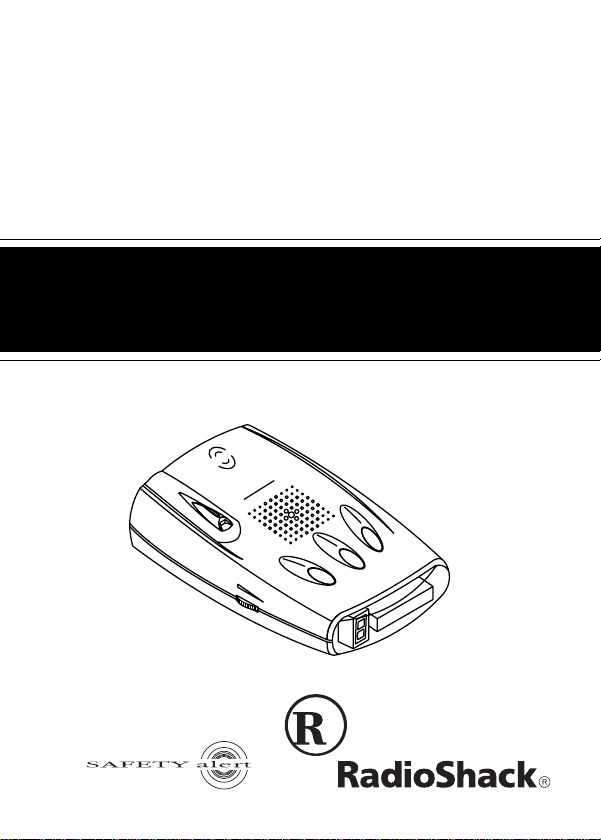
Talking 360°
Laser/Radar Detector
with VG-2 Guard
T
R
M
E
E
T
S
L
Y
S
A
G
IN
Y
N
T
R
A
E
W
F
IC
F
A
F
A
S
R
T
voice
LASER
CITY
MUTE
V
O
LU
M
E
/O
FF
DIM
2
G
V
a
K
/
K
X
A
S
Page 2

FEATURES
Your RadioShack Talking 360° Laser/Radar Detector ca n
alert you to all known police traffic radar and laser systems with its distinct visual and audio alerts, including a
real voice alert. It receives X-, K-, and Ka-band radar signals, and detects both the instant-on and laser systems
many police departments use to measure vehicle speed.
Plus, your detector can give you advance warning of potential road hazards by detecting signals from transmitters that broadcast Safety Alert System alerts.
Note
: Before reading this Owner’s Manual, read the sup-
plied booklet
Speed Detection
and uses associated with your detector.
Your detector’s features include:
Questions and Answers About Vehicle
to familiarize yourself with the terms
Real Voice Alert
— greets you as you turn on the detector and alerts you with 18 different vocal indicators including radar and laser detection.
360° Detection —
detects laser and radar signa ls from
all around your vehicle.
2002 RadioShack Corporation. All Rights Reserved.
RadioShack is a registered trademark used by RadioShack Corporation
2
©
Safety Alert is a trademark of Cobra Electronics.
F A ST is a registered trademark used by RadioShack Corporation.
Instaclear is a registered trademark used by Ford Motor Company.
ElectriClear is a registered trademark used by Libbey, Owens, Ford
and Delco-Remy.
.
Page 3

VG-2 Protection
— makes your detector invisible to the
VG-2 radar-detector detector when it senses VG-2 operation.
X-, K-, Ka-Band, and Laser Signal Detection
— warns
you when it detects signals from traffic radar or laser devices. Different tones and display indicators let you know
the type of signal received.
Safety Alert System Detection
— alerts you to the presence of potential road hazards, approaching emergency
vehicles, and busy railroad crossings broadcast by a
Safety Alert System transmission.
City/Highway Modes
— let you minimize alerts when
you are in areas that have false radar sources.
City/Highway Selector and City/Highway Indicator
—
displays which mode is currently selected.
FAST
(False Alert Suppression Technology)
— helps
prevent false alarms caused by non-traffic radar sources.
Tutorial Mode
— lets you experience how the detector
alerts you with its detection display, tones, and real voice
alert to all of the different signals the detector recognizes.
3
Page 4

Memory Retention
— retains operational settings in
memory without power, so when you turn on your detector, the settings will be the same as when you turned it
off.
Instant On or Pulse Radar Protectio n
— alerts you to
sudden high level radar and laser signals.
Your radar/laser detector includes the following items:
• coiled power cord
• windshield bracket with suction cups
• hook and loop tape
•spare fuse
•
Questions and Answers About Vehicle Speed Detection
We recommend you record your detector’s serial number
here. The number is on the detector’s bottom panel.
Serial Number: ________________________ _________
Important:
Some areas have laws regulating the use of
radar detectors. Check with your local law enforcement
agency about the laws in your area.
4
Page 5

CONTENTS
A Quick Look ............................................................... 6
Safety Alert System ................................................ 7
Installation ......................... .......................................... 8
Selecting a Mounting Location ............................... 8
Mounting Guidelines ........................................ 8
Windshield Mounting .............................................. 9
Hook-and-Loop Mounting ..................................... 11
Connecting Power .................................................... 12
Operation .............................. ..................................... 13
Turning On the Detector ....................................... 13
Adjusting the Volume ............................................ 13
Tutorial Mode ........................................................ 14
Starting the Tu to rial Mode ............................ .. 14
Selecting the Demonstration for Each Alert ... 14
Finishing the Tutorial Mode ............................ 15
Operation Settings .................... ............................ 15
Selecting the City and Highway Modes ......... 15
Selecting Display Brightness . ... ..................... 16
Muting the Audio Alert ................................... 17
Selecting VG-2 Mode ... ... ... .... ........................ 17
Receiving and Identifying Radar, Laser,
and Safety Alert Signals ....................................... 18
Troubleshooting ........................................................ 20
Care And Maintenance ............................................. 22
Replacing the Fuse .............................................. 23
FCC Statement .......................................................... 25
5
Page 6
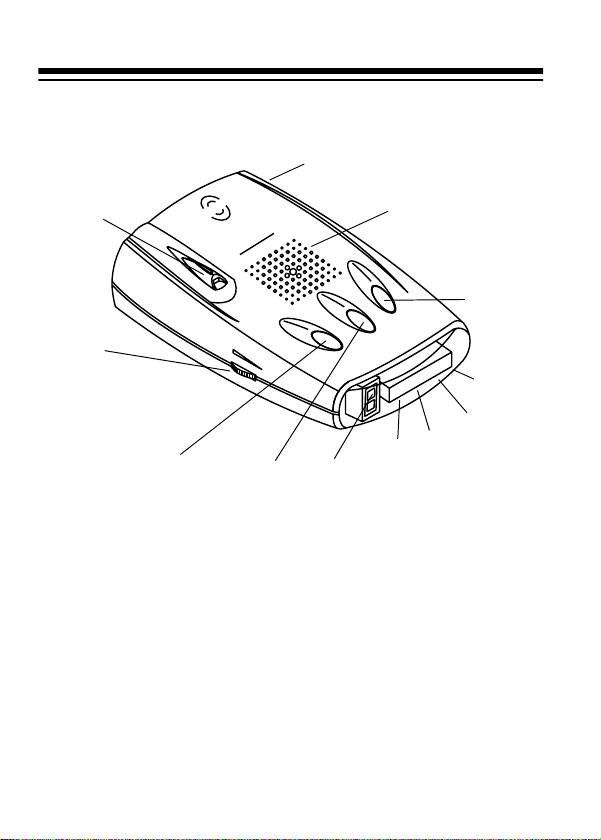
A QUICK LOOK
M
E
T
S
Y
S
G
IN
N
R
A
1.
W
IC
F
F
A
S A F E T Y A L E R T
R
T
voice
LASER
2.
6.
12.
360° Laser Eye
1.
VOLUME/OFF
3.
4.
— receives incoming laser signals
7.
IM
D
directed at your vehicle from all directions.
DC 12V Jack
2.
DIM Button
3.
— the power cord plugs in here.
— controls the brightness of your detec-
tor's single digit display.
MUTE Button
4.
— silences the alert tone and voice
alert for about 20 seconds.
CITY (City/Highway) Button
5.
— switches between
the city and highway modes.
Speaker
6.
6
— sounds digital voice alert.
Y
IT
C
E
T
U
M
A
S
5.
2
G
V
Ka
/
K
X
11.
10.
9.
8.
Page 7

Single Digit Display
7.
signal strength, safety alert, and laser alert.
SA Indicator
8.
the safety alert signals. (See “Safety Alert System.”)
X (X-Band Radar) Indicator
9.
detector detects an X-band radar signal.
K/Ka (K/Ka Band Radar) Indicator
10.
when the detector detects either a K- or Ka-band
radar signal.
VG-2 Indicator
11.
detected.
VOLUME/OFF Control
12.
off and lets you adjust the volume.
— displays when the detector detects
SAFETY ALERT
The Safety Alert System employs low-powered transmitters used by some emergency services and road crews
to alert drivers to hazardous road conditions. The system
can indicate stationary, moving, or railroad hazards.
The system has the potential to dramatically decrease
the occurrence of traffic accidents by increasing drivers'
awareness of local road hazards. Having this safety alert
compatible radar/laser detector will ensure that you are
ready to benefit from this system wherever it is in use.
— indicates city/highway mode,
— displays when the
— displays
— lights when a VG-2 signal is
— turns the detector on and
SYSTEM
7
Page 8

INSTALLATION
SELECTING A MOUNTING LOCATION
For the best performance, select a location for the detector where it has a direct view of the road. The detector's
radar antenna is at the opposite end from the display.
Note
: Though the detector has a 360° laser an d radar detection range, the radar detection is more sensitive in the
front range.
Mounting Guidelines
Follow these guidelines when selecting a location.
• Choose a location that does not block the driver’s
view of the road.
• Mount the detector in a level position with a clear
view to both the front and rear of your vehicle.
• The detector’s view of the road must not be blocked
by any metal object.
• Some vehicles have InstaClear
defogging windshields, which have metal coatings
that block signals. General Motor’s APV vans have a
solar shield that keeps the vehicle cooler during the
summer, but also blocks signals. A detector installed
in a vehicle with any of these features will probably
not detect a signal.
8
or ElectriClear
Page 9

• Since window tinting reduces the receiv ed st rength of
laser signals, you should not mount the detector
behind any tinted glass.
• Do not mount the detector where the driver or a pas-
senger might hit it in a sudden stop or accident.
Caution:
place it out of view when you leave the vehicle. This
keeps the detector out of sight of thieves and prevents
exposing it to extremely high temperatures, which can
temporarily impair performance.
However you choose to mount the detector,
WINDSHIELD MOUNTING
The supplied suction-cup windshield
bracket lets you easily mount the detector on the windshield.
Caution:
plastic coating on the windshield designed to protect passengers during an accident. If you use the bracket o n this
type of windshield, you might permanently mar the windshield’s surface. For an alternative mount ing method , see
“Hook-and-Loop Mounting” on Page 11 .
Do not use the bracket in a vehicle that has a
9
Page 10

1. Clean the selected windshield area, position the
bracket on the windshield, and press firmly on each
suction cup to secure it in place.
2. Slide the detector onto the base plate until it snaps
into place.
VOLUME/OFF
If it is necessary to adjust the mounting angle,
remove the detector from the bracket, then the
bracket from the windshield. Adjust the bracket by
carefully bending it.
10
Page 11

HOOK-AND-LOOP MOUNTING
V
O
L
U
M
E
/O
F
F
Place the tape on
the bottom of the
detector
In some vehicles, the dashboard ma y be
the best location to mount the detector.
For this mounting, use the supplied hookand-loop tape. Follow these steps to use
the hook-and-loop tape.
1. Use a damp cloth to clean the bottom of the detector
and the dashboard. Let both surfaces dry.
Note:
The tape’s adhesive might not stick to a sur-
face treated with vinyl cleaner or protectant.
2. Remove the tape’s backing and stick the tape to the
bottom of the detector.
Note:
Do not place the
hook-and-loop tape over the
detector’s serial number.
On a curved dashboard, cut
the supplied strip in half and
use one strip on each side of
the bottom of the detector.
Remove the backing from
the other side of the tape
and press the detector onto
the dashboard.
11
Page 12

CONNECTING POWER
Caution
Plug the supplied power cord’s barrel plug int o th e d et ector’s
plug into your vehicle’s cigarette-lighter socket.
Note:
on, remove the cigarette-lighter plug from your vehicle’s
socket and check the socket for ashes and other debris.
Also, check the fuse in the cigarette-lighter plug and your
vehicle’s fuse block (see “Replacing the Fuse” on Page
23).
:
• Use only the supplied power
cord. If your power cord is lost or
damaged, you can order a
replacement cord from your local RadioShack store.
• Before plugging the power cord’s cigarette-lighter
plug into your vehicle’s cigarette-lighter socket, make
sure the plug’s tip is screwed firmly onto the plug.
See “Replacing the Fuse” on Page 23 for more information about the cigarette-lighter plug.
• Unplug the power cord’s cigarette-lighter plug from
your vehicle’s cigar ette-lighter socket when you turn
off the ignition. This prevents your vehicle’s battery
from being drained if you leave the detector on when
you turn off the ignition.
DC 12V
jack. Then plug the cord’s cigarette-lighter
If the detector does not operate when you turn it
12
Page 13

OPERATION
TURNING ON THE DETECTOR
To turn on the detector,
rotate
VOLUME/OFF
ward
VOL U ME
clicks. The detector will
sound a tone, and will
greet you with its real voice alert — “Welcome! Buckle
your seat belt.”
dicate the detector is in highway mode (see “Selecting
the City and Highway Modes” on Page 15).
to-
until it
VOLUME/OFF
H appears on the single digit display to in-
To turn off the detector, rotate
VOLUME/OFF
until it clicks and all of the indicators turn off.
ADJUSTING THE VOLUME
Rotate
VOLUME/OFF
tector's volume, rotate it toward
ume.
toward
VOLUME
OFF
to increase the de-
to reduce the vol-
toward
OFF
13
Page 14

TUTORIAL MODE
Your detector has the tutorial mode to demonstrate all of
its alert indicators. In the tutorial m ode, you can ch eck the
status of all the indicators and the single digit display.
Starting the Tutorial Mode
To start the tutorial mode, turn on the detector while holding down
the detector sounds 3 beeps and
digit display.
Selecting the Demonstration for Each Alert
DIM
and
. The tutorial mode starts when
CITY
t appears on the single
To select the demonstration for each alert, press
The detector displays each alert indicator along with its
corresponding audio alert. The detector demonstrates
the alerts in the order of 1 to 8 as shown below.
1. X-Band Alert
2. K-Band Alert
3. Ka-Band Alert
4. Laser Alert
When the demonstration finishes,
single digit display.
14
5. Emergency Vehicle Alert
6. Road Hazard Alert
7. Rail Road Alert
8. VG-2 Alert
t appears again on the
DIM
.
Page 15

Finishing the Tutorial Mode
To finish the tutorial mode, press
when the voice alarm is operating.
at any time except
CITY
OPERATION SETTINGS
Selecting the City and Highway Modes
Your detector has two operating modes: city and highway. In city mode, the detector requ ire s a st ro nger X- , K-,
or Ka-band signal before it sounds or displays an alert.
Notes
:
• City mode helps prevent false alerts in tightly popu-
lated areas where laser/radar signals can bounce off
surrounding structures.
• The city mode has no effect on laser alerts or instant-
on radar.
The highway mode provides maximum sensitivity for
open-road driving. The unit is pre-set to highway mode
and
H appears on the single digit display when you turn it
on.
15
Page 16

To select the city mode, press
“city mode,” and
Note
: If you set the display brightness to dark mode, the
C appears on the single digit display.
single digit display shows only
. The voice alert says,
CITY
-. To show C or H, set the
display brightness to bright or dim mode. (See “Selecting
Display Brightness.”)
To return to the highway mode, press
voice alert says, “highway mode,” and
again. The
CITY
H appears on the
single digit display again.
Selecting Display Brightness
You can select from three levels of brightness fo r your radar detector: bright, dim, and dark.
Each time you turn on the detector, the display is pre-se t
to full brightness. Pressing
play's brightness by half, and the voice alert says, “dim.”
When you press
a second time, - appears on the
DIM
single digit display and the voice alert says, “dark.” While
the display is set to dark, X, K/Ka, VG-2, and SA indicators do not light during an alert. Pressing
returns the display to full brightness and the voice alarm
says, “bright.”
16
once reduces the dis-
DIM
a third time
DIM
Page 17

Muting the Audio Alert
While the detector sounds a radar or safety alert signal,
you can press
When you press
to temporarily silence the detector.
MUTE
, the voice alert says, “mute on.”
MUTE
The detector automatically resets the mute to off about
20 seconds after the radar or safety alert signal stops. Or,
you can simply press
again before it resets, and
MUTE
the voice alert says, “mute off.”
Note
: Laser alert signals are not affected by pressing
.
MUTE
Selecting VG-2 Mode
VG-2 mode is pre-set to off. To turn on VG-2 , hold down
until the voice alarm says, “VG-2 on.” To turn VG- 2
MUTE
off, hold down
off.”
until the voice alarm says, “VG-2
MUTE
17
Page 18

RECEIVING AND IDENTIFYING
RADAR , LASER, AND SAFETY ALERT
SIGNALS
When your detector senses a radar signal
appear on the display depending on which band is detected; it sounds an alert tone for the t ype o f ban d d etect ed; and the single digit display shows the signal strength
in numeric form.
X
Note
: The closer you get to the source of the radar, the
higher the signal strength number increases.
When your detector senses a laser signal
the single digit display and the detector sounds the laser
alert tone.
, X or K/Ka
K/Ka
, L flashes on
L
18
Page 19

For radar signal detection
X
VG-2
, if the signal strength number goes higher
than
3, the voice alert says, “X-
band detected,” “K-band detected,”
or “Ka-band detected,” respectively.
When your detector senses a safety alert signal
pears on the display;
ard alert), or
r (railroad warning) flashes on the single
E (emergency band), h (road haz-
, SA ap-
digit display; and the corresponding voice alert says,
“Caution, emergency vehicle,” “Caution, road hazard,” or
“Caution, moving train” depending on the type of signal
received.
SA
When VG-2 is detected
,
VG-2 appears on the dis-
play; the VG-2 alert tone
sounds; and the voice alert
says, “VG-2 detected.”
19
Page 20

TROUBLESHOOTING
If you have problems operating your detector, the suggestions in this section might help. If you cannot solve the
problem after trying these sug gestions, take your detector to your local RadioShack store for assistance.
Problem Suggestion
The detector does not
turn on.
Caution
rette lighter or cigarette-lighter plug in the cigarette-lighter
socket. Doing so could blow a fuse in your vehicle or cause
the metal object to become very hot.
: Do not place any metal object other than the ciga-
Be sure all power connections are
secure.
The cigarette-lighter socket might
be dirty. Clean it with fine emery
cloth to ensure a good, clean connection.
Check the fuse in the power cord's
cigarette lighter plug. See
“Replacing the Fuse” on Page 23.
Check the fuse that controls
power to your vehicle's cigarettelighter socket. See your vehicle's
owner's manual.
20
Page 21

Problem Suggestion
The detector gives a
false alert when you use
vehicle accessories such
as power windo w s,
motorized mirrors,
brakes, and so on.
The detector performs
the self-test, but does not
respond to radar signals
when you see a police
car.
The detector has poor
laser detection range.
Check the vehicle's electrical system for loose connections, including the main battery cable and
alternator connections.
Install a filter capacitor (1000 µF,
35 volts, such as RadioShack Cat.
No. 272-1032) on the back of the
cigarette lighter socket, across the
power connections.
A police car might not be
equipped with radar (see the supplied booklet,
Questions and
Answers About Vehicle Speed
Detection
Police might be using VASCARtype speed detection (see the
supplied booklet,
).
Questions and
Answers About Vehicle Speed
Detection
Be sure the laser detection lens is
not blocked.
Be sure the detector is properly
mounted. See “Selecting a Mounting Location” on Page 8.”
Use lens-cleaning solution to
clean the laser detection lens.
).
21
Page 22

CARE AND MAINTENANCE
Your RadioShack Talking 360° Laser /Ra da r Det ec tor is
an example of superior design and craftsmanship. The
following suggestions will help you care for your detector so you can enjoy it for years.
• Keep the detector dry. If it gets wet, wipe it dry
immediately. Liquids might contain minerals that
can corrode the electronic circuits.
• Keep the detector away from dust and dir t, which
can cause premature wear of parts.
• Handle the detector gently and carefully. Dropping
it can damage circuit boards and cases and can
cause the detector to work improperly.
• Wipe the detector with a damp cloth occasionally to
keep it looking new. Do not use harsh chemicals,
cleaning solvents, or strong detergents to clean the
detector.
Modifying or tampering with the detector’s inter nal components can cause a malfunction and might invalidate
its warranty. If your detector is not performing as it
should, take it to your local RadioShack store for assistance.
22
Page 23

REPLACING THE FUSE
If the detector stops operating, follow these steps to
check the fuse in the power cord's cigarette lighter plug
and replace it with a 2-amp, 1
(Cat. No. 270-1007), if necessary.
1
/4 × 1/4, fast-acting fuse
Caution
ments listed above can damage your detector, the power
cable, or the vehicle's electrical system.
1. Turn the knurled ring on the power cord's cigarette
2. Remove the ring and tip from the power cord's ciga-
3. Check the fuse. If it has blown, replace it.
: Using a fuse that does not meet the require-
lighter plug counterclockwise to unscrew it.
Caution
careful not to crush the ring or the metal tip inside th e
ring.
rette lighter plug, then remove the old fuse.
Note
spring inside the plug.
: If you must use pliers to loosen the ring, be
: Take care not to lose the ring or tip, or the
23
Page 24

4. Replace the metal tip inside the ring, make sure the
spring is intact, then place the fuse inside the cigarette-lighter plug and screw the ring back onto the
plug. Make sure the tip is visible when you reassemble the cigarette-lighter plug.
Caution
: Never use pliers or other tools to retighten
the ring on the cigarette-lighter plug.
24
Page 25

FCC STATEMENT
This device complies with Part 15 of the FCC Rules. Operation
subject to the following two condition s: (1) this device
is
may not cause
accept any interference received, including interference that
may cause undesired operation.
Changes or modifications not expressly ap proved by RadioShack may cause interference and void the user's authority to operate the equipment.
harmful interference, and (2) this device must
25
Page 26

NOTES
26
Page 27

27
Page 28

Limited One-Year Warranty
This product is warranted by RadioShack against manufacturing defects in material and workmanship under normal use for one (1) year from the date of purchase from RadioShack company-owned stores and authorized RadioShack
franchisees and dealers. EXCEPT AS PROVIDED HEREIN, RadioShack
MAKES NO EXPRESS WARRANTIES AND A NY I MPLIED WARRANTIES, INCLUDING THOSE OF MERCHANTABILITY AND FITNESS FOR A PARTICULAR PURPOSE, ARE LIMITED IN DURATION TO THE DURATION OF THE
WRITTEN LIMITED WARRANTIES CONTAINED HEREIN. EXCEPT AS PROVIDED HEREIN, RadioShack SHALL HAVE NO LIABILITY OR RESPONSIBILITY TO CUSTOMER OR ANY OTHER PERSON OR ENTITY WITH
RESPECT TO ANY LIABILITY, LOSS OR DAMAGE CAUSED DIRECTLY OR
INDIRECTLY BY USE OR PERFORMANCE OF THE PRODUCT OR ARISING
OUT OF ANY BREACH OF THIS WARRANTY, INCLUDING, BUT NOT LIMITED TO, ANY DAMAGES RESULTING FROM INCONVENIENCE, LOSS OF
TIME, DATA, PROPERTY, REVENUE, OR PROFIT OR ANY INDIRECT, SPECIAL, INCIDENTAL, OR CONSEQUENTIAL DAMAGES, EVEN IF RadioShack
HAS BEEN ADVISED OF THE POSSIBILITY OF SUCH DAMAGES.
Some states do not allow limitations on how long an implied warranty lasts or
the exclusion or limitation of incidental or consequential damages, so the ab ove
limitations or exclusions may not apply to you.
In the event of a product defect during the warranty period, take the product
and the RadioShack sales receipt as proof of purchase date to any RadioShack
store. RadioShack will, at its option, unless otherwise provided by law: (a) correct the defect by product repair without charge for parts and labor; (b) replace
the product with one of the same or similar design; or (c) refund the purchase
price. All replaced parts and products, and products on which a refun d is made,
become the property of RadioShack. New or reconditioned parts and products
may be used in the performance of warranty service. Repaired or replaced
parts and products are warranted for the remainder of the original warranty period. Y ou wi ll be charg ed for rep air or r eplacement of the p roduct ma de aft er the
expiration of the warranty period.
This warranty does not cover: (a) damage or failure caused by or attributable t o
acts of God, abuse, accident, misuse, improper or abnormal usage, failure to
follow instructions, improper installation or maintenance, alteration, lightning or
other incidence of excess voltage or current; (b) any repairs other than those
provided by a RadioShack Authorized Service Facility; (c) consumables such
as fuses or batteries; (d) cosmetic damage; (e) transportation, shipping or insurance costs; or (f) costs of product removal, installation, set-up service adjustment or reinstallation.
This warranty gives you specific legal rights, and you may also have other
rights which vary from state to state.
RadioShack Customer Relations, 200 Taylor Street, 6th Floor, Fort Worth, TX
76102
12/99
09A02 Printed in Korea
 Loading...