

User Manual for RF module/Receiver
TX (RF module) RX (Receiver)
Be sure to read a user manual before its u sage

Product Overviews
When it comes to the existing RF module/Receiver for PC, it is impossible to use the
same frequency at the same time due to the interference between frequencies, which
resulting in low reuse of frequency. Also the said product has lots of problems such as
vulnerability to outside signals and multi users’ inconvenience for spontaneous use.
This product employs digital communication method in 2.4GHz of ISM band to take care
of the said interference between frequencies and also fast transmission rate and fine
resolution for flexible operation.
It is designed so that unique ID would be assigned for each RF module and related
Receiver and RF module should communicate mutually using the said ID for ID setting.
In other words, Receiver has only ID of RF module finally set and get only data
transmitted from the said RF. Also for interference between wireless frequencies, it
check-ups RF environments to acquire stable communication on ID setting that in turn
be sure to configure the most superior channel as communication one.
For the said features, RF module and Receiver can perform related functions without
any data loss even for external interference.
Cautions and safety
Safety
Be sure to read User manual before its usage
Do not attempt to dismantle product. Otherwise it may result in malfunction
For RF module and Receiver, it should be attached after turn off power (control and model)
After connecting RF module to control, be sure to position control’s throttle level on stop and turn
on control power and Receiver one in order.
Caution
When turning off power, be sure to turn off engine or motor and then receiver power and control
one in order.
In case of wrong operation, there may be a danger of spontaneous miss-operation.
Be sure to take an operation test between RF module and Receiver before its control
Be sure to operate each channel for normal operation. If there is any problem, never attempt to
operate it.
For Receiver attachment, please make a dust-proof device from Styrofoam. Especially dust-proof
procedure may be recommended for engine part
Do not attempt to modify antenna’s length voluntarily
Please make sure that antenna should not be covered with airframe’s internal section or lid with
metal paint or carbon fiber. Otherwise it may decrease radio wave’s efficiency.
Do not use any combination of Radiopost RF module and other vendor’s Receiver or reversely.
We never hold any responsibility for any damages from any combination with other vendor’s
receiver or RF module.
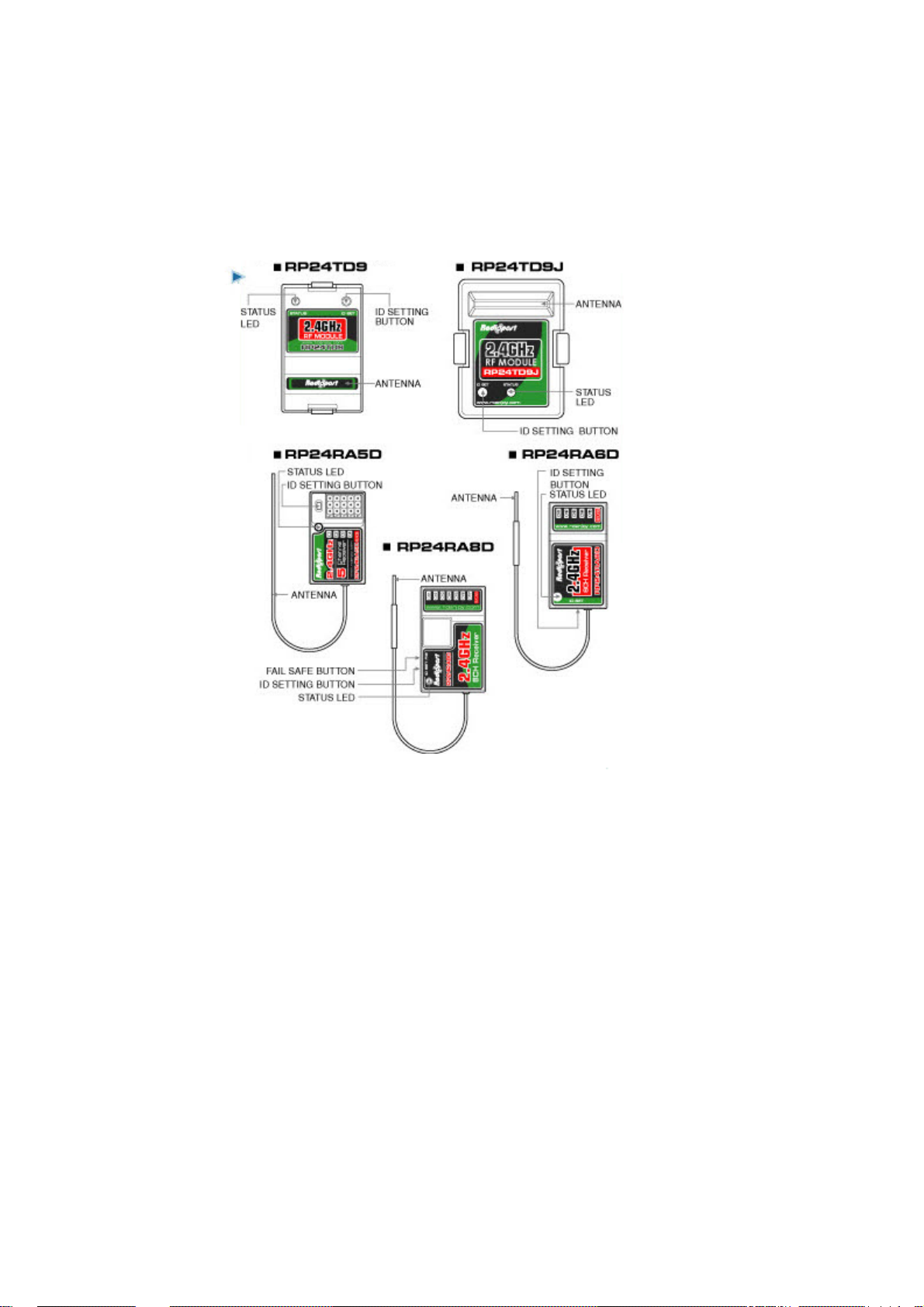
Designation of each part by model
Futaba/Hiltec controller JR controller
RF module
Receiver

Product Features
Superior stability with 2.4GHz band
2.4GHz auto channel configuration (no crystal required)
Confirmation of ID-setting with Sound could be possible
Excellent binding speed
RF module
As RF module’s antenna is internal type, it gives convenience when
attaching a stand on a controller.
Radipost RF module’s antenna gives high efficiency (7dBi) compared with
the existing antenna’s efficiency (2-3dBi)
Radipost RF module can communicate with Radiopost Receiver at all
channels.
Receiver
It may be strong and has wide range of operation and good durability.
It is a high sensitive receiver not interfered with mixed modulation and
inter-modulation
It employs stable top-notch digital technology
As it adopts digital method with MCU, It is possible to operate stably
It is a universal type that may be used under optimal conditions for
helicopter, glider, airplane, vehicles, etc.
As it can recognize only user’s RF module with advanced set, it is possible to be out of
No Control situation
For worst circumstance, it can prevent dangers with Fail Safe function. (only for
RP24RS8D)

LED Display
RF module
When you apply power at the first purchase, LED may stay in red
When you press ID-setting button, ID-setting mode displays and LED may blinking in red
When ID-setting completes, LED turns to green and stay in that color
When you apply power to RF module only without Receiver after pairing, it may start to search
for Receiver and LED may blink in green.
1: Red Lamp (on)
2: Red Lamp (blink)
3: Green Lamp (on)
4: Green Lam p ( blink)
5: Green Lam p ( blink)
6: Red Lamp (blink)
7: Green Lamp (on)
8: Red Lamp (blink)

How to use
Be sure to select RF module suitable for controller and confirm connector’s position and assemble
it
For Receiver, be sure to confirm polarity of servo and battery before connecting them properly.
When you connect RF module to controller and turn it on, you can hear a sound of “pi” three
times and LED turn on and remain in red
Be sure to apply power to Receiver
When you apply power to Receiver, white LED on Receiver is blinking
When you press ID-setting button of RF module for a second, it enters into ID-setting and red
LED of RF module is blinking
When you press ID-setting button of Receiver for a second, it enters into ID-setting and red LED
of RF module is blinking
When ID-setting of RF module and Receiver completes, RF module’s LED turns to green. When
you can hear a sound of ‘pi” two times, it indicates that ID-setting completes.
Be sure to move the lever of controller and confirm operating status of servo finally.

Fail Safe (R P24RA8D model only)
This is a function that move servo to pre-set position against radio disturbance during
its flight
If you place a controller to neutral position and turn throttle into idle or motor-stop
status for Fail Safe configuration and the said function works due to the receive
interruption, servo may move to pre-set position till signal would sensed for minimizing
the destruction of air-frame.
How to set up Fail Safe
How to turn on F ail Safe
Be sure to turn power of RF module and Receiver in order and move a controller to
confirm operating status of servo and Paring.
Be sure to operate a controller to move servo to Fail Safe position
When you press Fail Safe button for 3 seconds, red led is flickering for Fail Safe mode
How to turn off
When you press Fail Safe button for 3 seconds, red led is flickering and Fail Safe mode
is disabled.
When you attempt to set up Fail Safe with a Receiver connected to a device, be sure to
turn engine power ch a nn el into hold or power source should be disconnecte d.

Specificat io ns
Controllers compatible
This product is compatible for controller supporting PPM mode
Futaba
FF7A, FF9, 10C (Airplane/Helicopter)
Mega Tech 3PM-FS, 3PK (Vehicles)
Hiltec
OPTIC 6, ECLIPSE (Airplane/Helicopter)
Aggressor CRX, Aggressor SRX, Eclipse Procar (Vehicles)
JR
9X LIMITED, 10X (Airplane/Helicopter)

Product Warranty
1. For product’s warranty period, it is one year from a date of its purchase. If
there is any problem under normal use within the said period, we have to repair
with no charge.
2. If the following things occur within warranty period, you may take a charge
service
■ Malfunction caused by user’s careless handling
■ User’s dismantle, repair, alteration at his (or her) own will
■ Malfunction caused by other repair center or personnel than our service technician or
designated after-sales service center
■ Malfunction caused by natural calamities
■ Consumption goods replacement
■ if there is no information such as date of purchase, customer name, store name or
such information would be modified by customer voluntarily
3. For any responsibility related with this product, it should be limited to its repair
or replacement.
4. When there is any problem for product, please contact with related store or call
the following contact address
Model
Date of Purchase Warranty Period: 12 months
Purchasing store Purchase Price:
Telephone Others:
Customer
RF module RP24TD9/RP24TD9J
Receiver RP24RA5D/RP24RA60/RP24RA8D
from a date of purch a se
Name
Address
Telephone

About After-sales service
■ If there is malfunction or any problem, please stop its operation and contact with
purchase store or our headquarter for after-sales service
■ Customer supporting center: 080-080-6066 (09:00-18:00: Business day)
■ Nextlink
Address: Chungangindus 2
Sungnam city, Kyunggi-do
nd
701#, 144-5, Sang-daewon-dong, Chungwon-gu,
www.rcenjoy.com
* FCC RF Radiation Exposure Statement
This equipment complies with FCC RF radiation exposure limits
set forth for an uncontrolled environment. This equipment is a handheld device and
should be maintained with a minimum safety distance of 20cm from the antenna.
This transmitter must not be co-located or operated in conjunction with any other
antenna or transmitter.
 Loading...