

Radionet RNFCC1 User Manual

Radionet RN-900FCC/IC
User Guide
USER GUIDE
RN-900FCC/IC
Version 1.9.11
Copyright © Radionet, 2005. All rights reserved.
1 / 48

Radionet RN-900FCC/IC
User Guide
Trademarks Copyright
Internet Explorer is a trademark of Microsoft Corp. Copyright © 2005 by Radionet Ltd.
Mozilla is a trademark of the The Mozilla Organization. All rights reserved. No part of this book shall be reproduced, stored
Netscape is a trademark of Netscape Communications Corporation.
All terms mentioned in this book that are known to be trademarks
or service marks have been appropriately marked. The publisher
cannot attest to the accuracy of this information. Use of a term in
this book should not be regarded as affecting the validity of any
trademark or service mark.
in a retrieval system, or transmitted by any means, electronic,
mechanical, photocopying, recording, or otherwise, without prior
written permission from the publisher. No patent liability is assumed
with respect to the use of the information contained herein.
Although every precaution has been taken in the preparation of this
book, the publisher and authors assume no responsibility for errors
or omissions. Nor is any liability assumed for damages resulting
from the use of the information contained herein.
Disclaimer Contact information
While every effort has been made to make this book as complete
and as accurate as possible, no warranty or fitness is implied. The
information provided here is on an "as is" basis. The authors and
the publisher shall have neither liability nor responsibility to any
person or entity with respect to any loss or damages arising from
the information contained in this book.
http://www.radionet.com
Radionet, Ltd.
Valkjärventie 7 C
FIN-02130 ESPOO
Finland
tel. +358 9 4392 1070
fax. +358 9 412 6762
Copyright © Radionet, 2005. All rights reserved.
2 / 48

Radionet RN-900FCC/IC
User Guide
General ............................................................................... 16
Table of contents
Table of contents ....................................................................3
Safety instructions ..................................................................5
Note on electromagnetic emissions......................................... 5
Regulatory notice.................................................................5
Introduction ...........................................................................6
Package contents ....................................................................6
Physical interfaces and description.............................................7
Antenna .............................................................................7
Aluminum enclosure.............................................................7
Connectors .........................................................................7
Installation instructions............................................................ 7
Installation direction.............................................................8
Antenna mast installation......................................................8
Aligning the antenna ............................................................8
Power divider ......................................................................8
Grounding ..........................................................................9
Power cabling using PSU-3 power supply.................................9
Power cabling using PSU-2 power supply (accessory) ................9
Ethernet cabling ................................................................ 10
Protective connector cover............................................... 10
Applying coax seal tape ......................................................10
Configuration overview - Before you begin................................ 11
Connecting to the Radionet RN-900FCC products.................... 11
Establishing the initial connection......................................11
The configuration Home page ................................................. 13
System............................................................................. 13
Associations ...................................................................... 13
Networking .......................................................................14
Action log .........................................................................14
Navigating the configuration menu .......................................... 14
Saving and committing changes........................................... 15
OK ............................................................................... 15
Commit Settings............................................................. 15
Copyright © Radionet, 2005. All rights reserved.
3 / 48
Associations and nodes.......................................................... 17
Networking .......................................................................... 18
Changing Ethernet settings ................................................. 18
Basic interface settings ...................................................... 18
Changing bridge settings .................................................... 19
Changing radio interface settings......................................... 20
Editing the routing table ..................................................... 23
Security .............................................................................. 24
Configuring remote login services ........................................ 24
Interface status ............................................................. 19
Editing existing IP addresses............................................ 19
Adding a new IP address ................................................. 19
To add a new IP address ................................................. 19
Transparent bridging with Ethernet tunnel ......................... 19
Removing an interface from the bridge.............................. 20
To remove an interface from the bridge............................. 20
Binding an interface to the bridge..................................... 20
To bind an interface to the bridge..................................... 20
Edit the SSID ................................................................ 21
Set the Wireless mode .................................................... 21
Set the Operation mode .................................................. 21
Choose the antenna type................................................. 21
Set the Operating Frequency ........................................... 21
Set transmit power......................................................... 22
Set the RTS threshold..................................................... 22
Set the Fragmentation threshold ...................................... 22
Suppress/Enable SSID broadcast...................................... 22
Enable AES encryption .................................................... 22
WPA-PSK passphrase...................................................... 22
Editing an existing route ................................................. 23
Adding a new route ........................................................ 23
To add a new route ........................................................ 23
Default gateway............................................................. 23
SSH ............................................................................. 24
HTTP ............................................................................ 25

Radionet RN-900FCC/IC
User Guide
HTTPS........................................................................... 25 APPENDIX 1: Detailed instructions for cabling ........................... 42
Configuring administrator accounts....................................... 25 Power cabling ................................................................... 42
Adding a new administrator account.................................. 26 Ethernet cabling ................................................................ 43
Deleting an administrator account..................................... 26 APPENDIX 2: Further reading ................................................. 45
Editing administrator passwords ....................................... 26 APPENDIX 3: Factory Settings ................................................ 46
Services............................................................................... 27 APPENDIX 4: Allowed channels in 2,4 GHz and 5 GHz frequency
bands ................................................................................. 47
Configuring the DHCP server ............................................ 27 APPENDIX 5: Allowed transmit power levels, and radio + antenna
combinations with Radionet FCC/IC-Canada products................. 48
Client IP pool ................................................................. 28
Client network settings.................................................... 28
DHCP Relay....................................................................... 29
MageIP............................................................................. 29
SNMP ............................................................................... 30
Remote Syslog .................................................................. 31
Utilities................................................................................ 32
ARP table.......................................................................... 32
Viewing the ARP table ..................................................... 32
Ping & Traceroute .............................................................. 33
Ping.............................................................................. 33
Traceroute..................................................................... 34
Arping........................................................................... 34
Software.............................................................................. 35
Using the Software Update page .......................................... 35
Factory Defaults ............................................................. 36
Log ..................................................................................... 37
Viewing log entries............................................................. 37
Recent Entries................................................................ 37
Minimum Level............................................................... 38
Sort by ......................................................................... 38
The Action Log .................................................................. 38
Adding a log entry ............................................................. 38
Log messages ................................................................... 39
Resetting the unit.................................................................. 40
Warranty .............................................................................41
Disclaimer............................................................................ 41
DHCP server ..................................................................... 27
General DHCP Server Settings.......................................... 27
Copyright © Radionet, 2005. All rights reserved.
4 / 48

Radionet RN-900FCC/IC
User Guide
Safety instructions
This document must be reviewed for familiarization with the product
and instructions before operation.
Verify that an un-interruptible safety earth ground exists from main
power source and the ground circuitry of the product.
Verify that correct AC power source is available for the AC adapter
to produce 12...30 VDC for the product.
Disconnect the product from operating power before cleaning.
L Warning!
A professional installer must install the base station and antennas.
You are cautioned that changes or modifications not expressly
approved by the part responsible for compliance could void the
user's authority to operate the equipment. (FCC 15.21)
Note on electromagnetic emissions
This device complies with part 15 of the Federal Communications
Commission (FCC) rules. Operation is subjected to the following
conditions:
1. This device may not cause harmful interference.
2. This device must accept any interference received including
interference that cause undesired operation
3. Warning! Electromagnetic radiation. Please keep this product
and related antennas at a distance 20 cm from human body.
Regulatory notice
The specifications and parameters of the device described in this
document are subject to change without notice.
For American regulatory information, see www.fcc.gov. For
Canadian regulatory information, see www.ic.gc.ca.
This equipment generates, uses and radiates energy on radio
frequencies and, if not installed and used in accordance with this
guide, may cause harmful interference to radio communications.
However, there is no guarantee that interference will not occur in a
particular installation.
If this equipment does cause harmful interference to radio or
television reception, which can be determined by turning the
equipment off and on, the user is encouraged to correct the
interference by one or more of the following methods:
- reorient or relocate the receiving antenna
- move the equipment and receiver farther apart
- connect equipment to an outlet on a circuit different from
that to which the receiver is connected
Please study first allowed regulatory guidelines shown in Appendix
5, which describe allowed product configurations. Radionet RN 900
FCC/IC-Canada product is only allowed to be used with Radionet
antennas and accessories (PSU-3 power supply) and power dividers.
In USA and Canada maximum allowed transmit power levels and
channel frequencies are shown in Appendix 5.
Copyright © Radionet, 2005. All rights reserved.
5 / 48

Radionet RN-900FCC/IC
User Guide
Introduction
This guide contains information on how to operate and manage the
Radionet RN-900FCC products.
Package contents
The Radionet RN-900FCC package contains the following items:
• Radionet RN-900FCC product
• Mounting kit with downtilt
• One weather proof power connector kit
• One weather proof RJ-45 connector kit
• Outdoor power supply unit PSU-3
• Factory default tool
• Mounting instruction
• Documentation CD-ROM
Copyright © Radionet, 2005. All rights reserved.
6 / 48
Radionet RN-900FCC/IC
User Guide
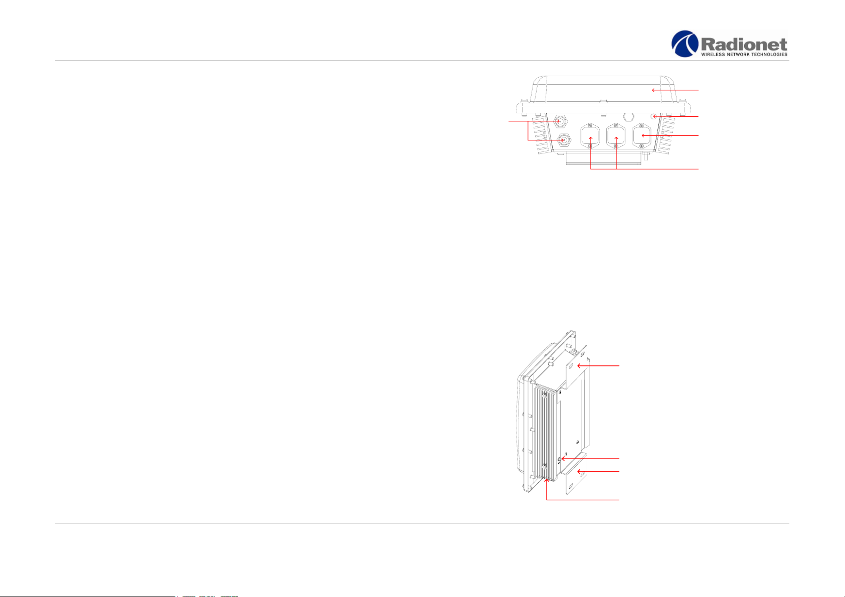
Physical interfaces and description
Key features of the Radionet RN-900FCC are:
• Aluminum enclosure supports outdoor installation
• Industrial temperature rating (-40…+55 °C)
• Two external antenna connectors
• Two 10/100 Base TX Ethernet ports
• Activity indication LED
• Detachable power connection with RS-485 connection for
remote management
Antenna
The Radionet RN-900FCC is delivered with an integrated 5 GHz
20dBi patch antenna. Integrated link antenna element is covered
with a white radome to protect it.
Aluminum enclosure
The base station unit uses an aluminum enclosure that supports
outdoor operating environments and supports an industrial
temperature operating range.
Integrated antenna
Female N-type connectors
for external antennas
Indication LED
Power con nector with
RS-485 for remote
connection
Ethernet connectors
Overview of the Radionet RN-900FCC
Installation instructions
The Radionet RN-900FCC is designed for outdoor installation
environment, on a tower, a tall building or an antenna mast.
A professional installer must install the base station and antennas.
The installer should also be familiar with network structures, terms,
and concepts.
Upper mounting bracket
Connectors
All connectors are located on the bottom of the housing. The RN900FCC has two external antenna connectors and two Ethernet
connectors.
Copyright © Radionet, 2005. All rights reserved.
7 / 48
Grounding bolt
Lower mounting bracket
Aluminum enclosure
Radionet RN-900FCC/IC
User Guide
Installation direction
Connectors must always be downwards in outdoor installations. In
indoor installations (e.g. warehouses etc.) direction can be freely
selected if integrated antenna is not used.
Aligning the antenna
Installation technician must mechanically align the antennas for the
best possible coverage.
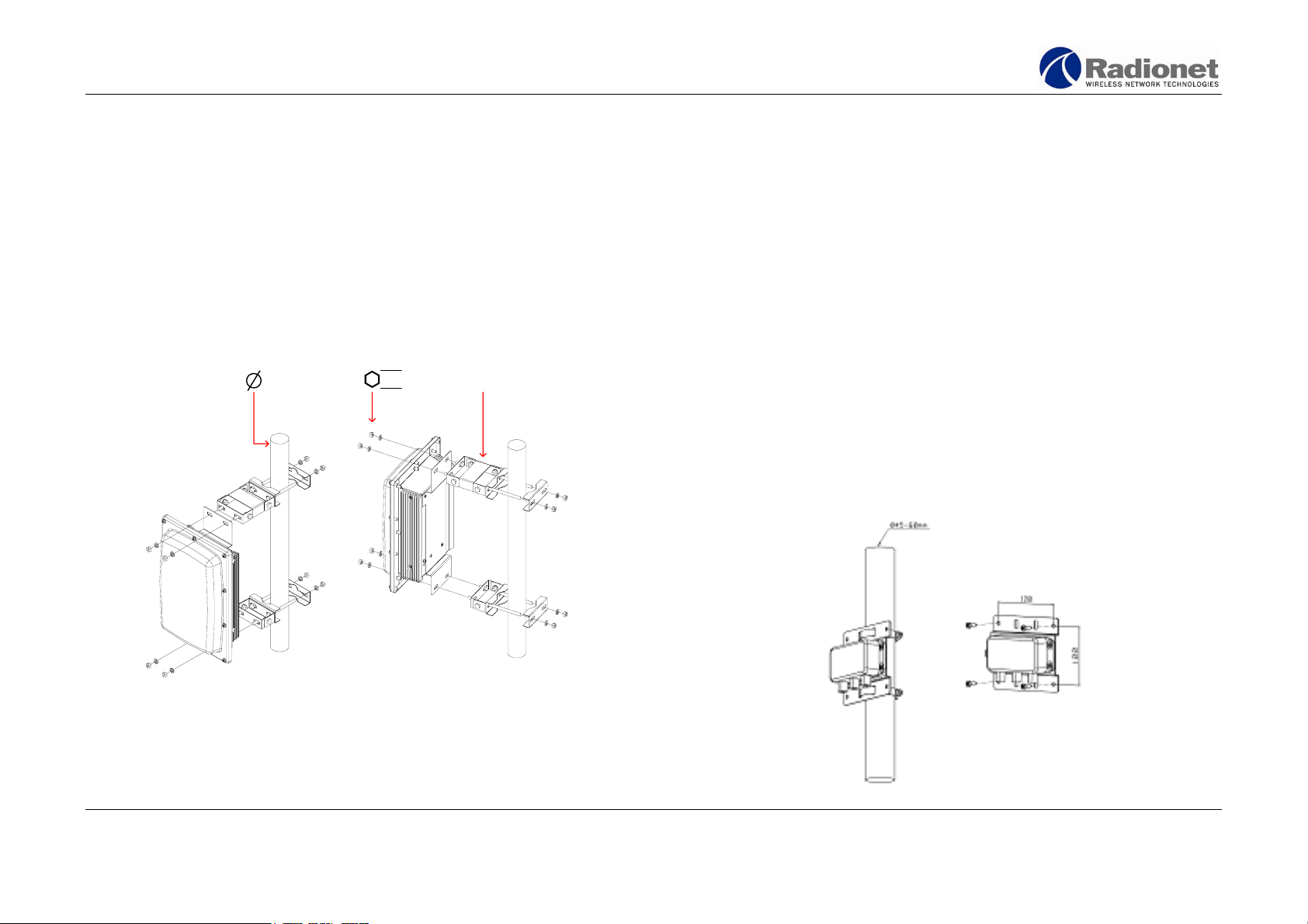
Antenna mast installation
The following figures present installation in antenna mast pipe;
antenna pipe diameters 45…60mm (approx. 1 3/4…2 1/3 inches).
45-60 mm RN-TLT-1
13 mm
Power divider
You may connect two sector antennas to one radio by using a power
divider. For the best possible operation, the antennas using the
same radio should point directly opposite directions from each
other. Also the length of the cables between the antennas and the
power divider should be the same to ensure even signal strength to
both cells.
The power divider reduces the output signal level by 3 dBm.
The following figures present the installation of the power divider.
Copyright © Radionet, 2005. All rights reserved.
8 / 48
Radionet RN-900FCC/IC
User Guide
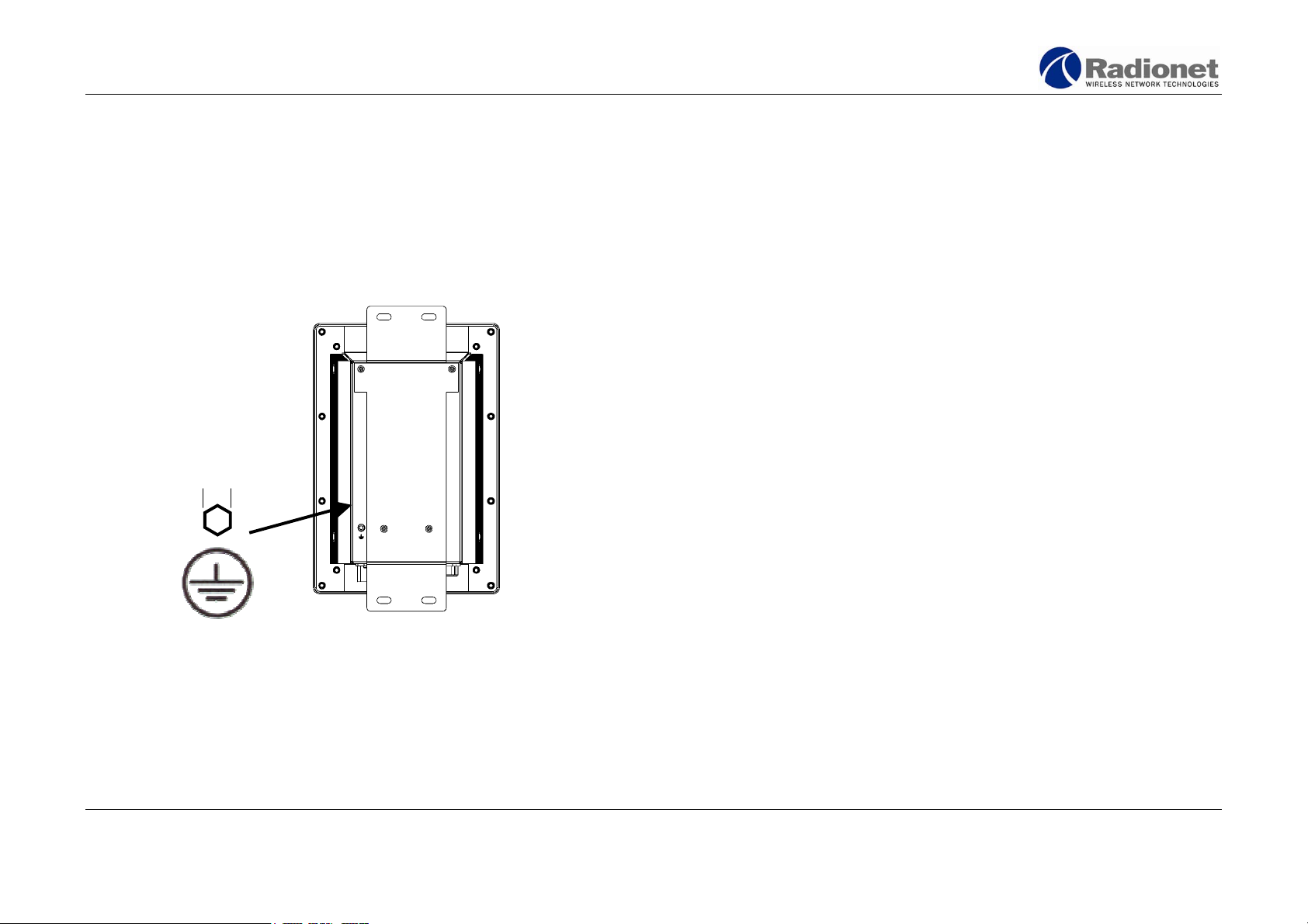
Grounding Power cabling using PSU-3 power supply
Grounding bolt with hex nut is located on the backside of the base
station. Unit must always be grounded to the building ground using
16 mm
2
(#6 AWG) grounding cable.
8 mm
The PSU-3 power supply unit can feed one RN-900FCC base station
product. The power supply is an external unit designed for operation
in outdoor environment. The supply voltage of the power supply is
24 VDC. The power supply unit provides RS-485 connector for
remote management of the base station unit. RS-485 pins must be
wired from the base station unit to power supply if RS-485 remote
management is needed. Wiring can be done by 4-wire power cable.
RS-485 is a data communications interface standard approved by
the Electronic Industries Association (EIA) for multipoint
communications with serial devices. It is ideal for industrial
applications due to its noise immunity.
The transmitted data is represented by voltage differences between
the two wires of the power cable. RS-485 requires specific serial
port hardware that supports RS-485 voltages and conventions.
Detailed cabling instructions are in Appendix 1.
Power cabling using PSU-2 power supply (accessory)
The PSU-2 power supply is an external unit designed for operation
in outdoor environment. The PSU-2 power supply unit can feed up
to two Radionet RN-900FCC products. The supply voltage of power
supply is 12 VDC. The power supply unit has an inbuilt sealed leadacid rechargeable battery to ensure at least few minutes of
operation when the main supply voltage is lost. This battery backup time depends on the condition of the battery. It is recommended
to replace the battery from time to time, e.g. once a year. This
Copyright © Radionet, 2005. All rights reserved.
9 / 48

Radionet RN-900FCC/IC
User Guide
replacement time depends on ambient temperature of the power
supply unit.
Ethernet cabling
The maximum length of Ethernet cabling without repeaters or
amplifiers is 100 meters (330 feet). Ethernet cabling must fulfill
CAT5 category FTP outdoor cable specifications. Detailed cabling
instructions can be found in Appendix 1.
Protective connector cover
If the Ethernet connectors are not used you must cover the
connectors by a protective cover. Radionet RN-900FCC is shipped
with protective covers on both Ethernet connectors by default.
Applying coax seal tape
When using the unit with external antennas, you must weather seal
the N connectors using seal tape. N connectors that are not properly
sealed permit moisture to enter the connection, which leads to
performance degradation or coverage problems.
Copyright © Radionet, 2005. All rights reserved.
10 / 48

Radionet RN-900FCC/IC
User Guide
Configuration overview - Before you begin
Ensure that the Radionet RN-900FCC is connected to your computer
(with a cross wired Ethernet cable) or your network (through a
switch or a hub). You will need to obtain the following information
from your network administrator to successfully configure the
Radionet RN-900FCC:
1. IP addresses for each interface of your Radionet RN-900FCC,
if your network is not connected to a DHCP server.
2. The radio settings appropriate to your network and hardware
(see page 20).
Connecting to the Radionet RN-900FCC products
The Radionet RN-900FCC is configured via a practical web-based
configuration utility. The configuration utility can be accessed using
an ordinary web browser, and allows you to edit, manage and
monitor your Radionet RN-900FCC settings and functionality.
The configuration utility supports the following web browsers:
• Internet Explorer versions 5.0, or higher
• Mozilla versions 0.9, or higher
• Netscape Navigator versions 6.1, or higher
• Opera, versions 7, or higher
Other web browsers may also be acceptable, but have not been
tested. Only the web browsers listed above can be guaranteed to
function correctly when used to configure the Radionet RN-900FCC.
Establishing the initial connection
First, plug in the power cable of the Radionet RN-900FCC to power
up the unit.
Establish a physical connection to the RN-900FCC. If you are using
a laptop or a desktop computer, this can be done using a cross
wired twisted pair Ethernet cable to connect your PC to ethernet1
port of the RN-900FCC.
Set your computer IP addresses as follows:
• IP address: 192.168.1.2
• Subnet mask: 255.255.255.0
Once the unit is powered up and your IP parameters are set, you
may use your web browser to connect to the IP address of the
Radionet RN-900FCC. The Radionet RN-900FCC is pre-configured
with default IP addresses “192.168.1.1” on the ethernet1 interface.
Copyright © Radionet, 2005. All rights reserved.
11 / 48
Radionet RN-900FCC/IC
User Guide
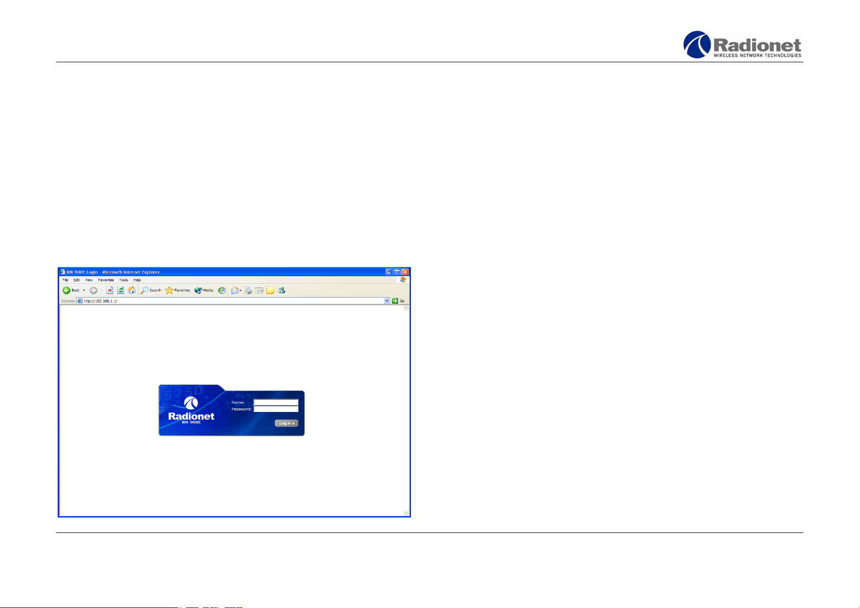
Providing username and password
Default IP address
Factory default value: 192.168.1.1
Default IP address may be later changed by an administrator (see
page 19 for information about changing the IP address of an
interface). To connect to the configuration utility, perform the
following steps:
1. Enter the IP address of the Radionet RN-900FCC in your
browser's address or location bar.
2. Press ENTER. This will bring you to the login screen shown in
Figure 1.
Enter your administrator username and password into the fields on
the login page. When shipped, the Radionet RN-900FCC is pre-set
with a single default administrator account. To access this account,
use the following login information:
Username: admin
Password: default
Usernames and passwords are case-sensitive. Additional
administrator accounts and passwords can be set up from the
Security menu (see page 24). To protect your Radionet RN-900FCC
against unauthorized access, Radionet strongly recommends that
you change the default password as soon as possible
Click the OK button to send your login information to the Radionet
RN-900FCC. Once you have successfully logged in, you will be
presented with the Radionet RN-900FCC configuration menu and
Home page.
Figure 1: The login screen of Radionet RN-900FCC products
Copyright © Radionet, 2005. All rights reserved.
Note! As a security measure, the RN-900FCC configuration utility will
automatically log you out after 15 minutes of inactivity. If this
happens, simply enter your administrator username and password at
the login page again.
12 / 48
Radionet RN-900FCC/IC
User Guide
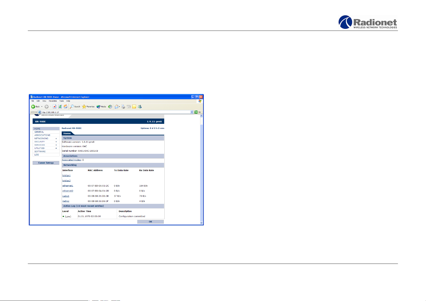
The configuration Home page
Upon logging in, you will first see the Radionet RN-900FCC
configuration Home page, shown in Figure 2.
Note! Depending on your choice of web-browser, your screen may
not appear exactly as depicted in this document.
The Home page displays a brief summary of the configuration and
current status of your Radionet RN-900FCC product. At the top of
the page you can read the name and uptime of the device.
Additional information about the Radionet RN-900FCC is grouped
under the four sections: System, Associations, Networking, and
Action log. These constitute the remainder of the page.
System
The system info section displays the following information regarding
your Radionet RN-900FCC unit.
Software version
The firmware version of the unit. For information about
updating the Radionet RN-900FCC firmware, consult page
35.
Hardware version
The hardware version of the unit.
Serial number
The serial number of your unit. This number is important
when you need to contact customer service.
Associations
Figure 2: The configuration Home page
Copyright © Radionet, 2005. All rights reserved.
13 / 48
If your Radionet RN-900FCC is used by wireless end-users, the
number of associated nodes is displayed here.
Radionet RN-900FCC/IC
User Guide
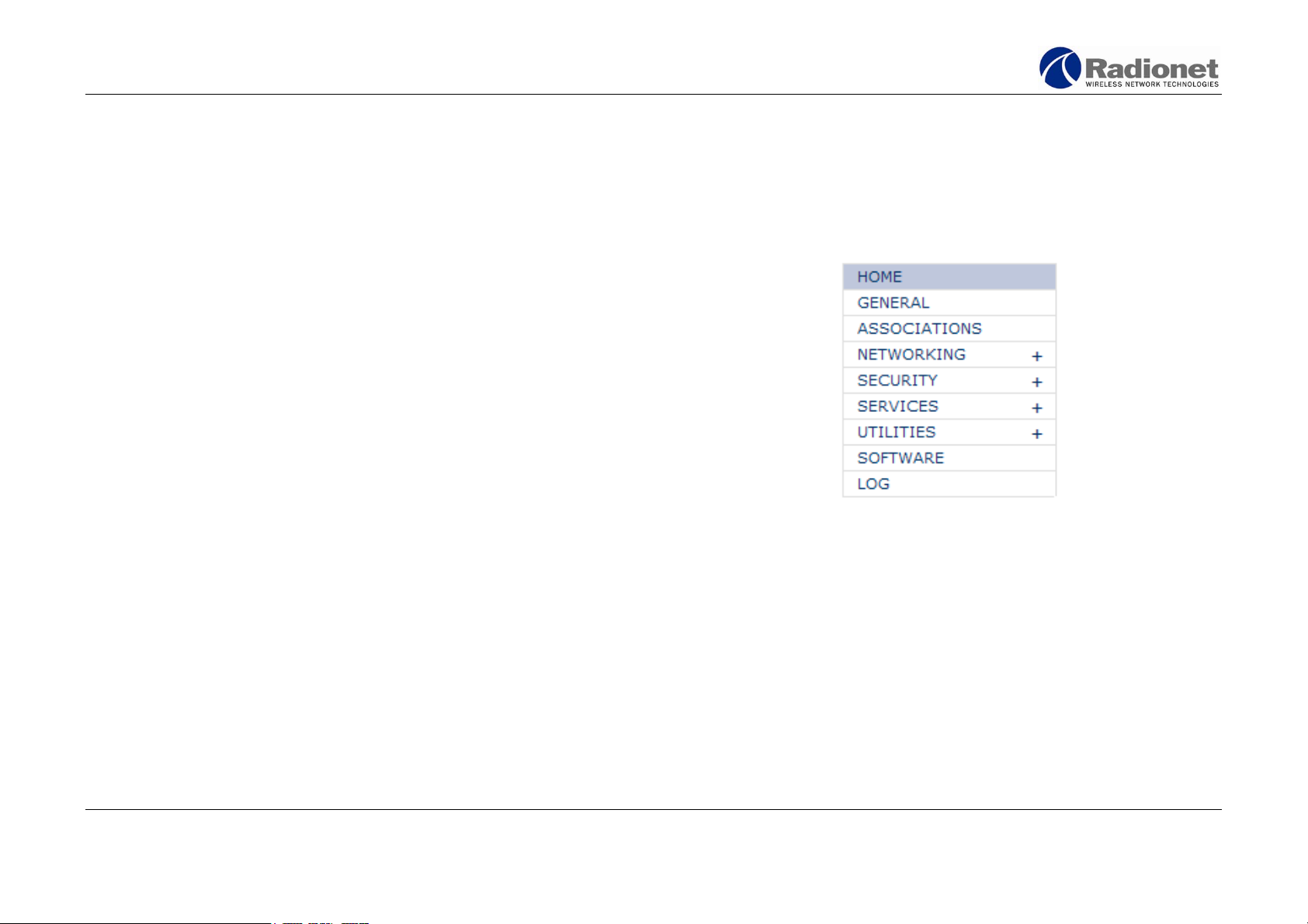
Navigating the configuration menu
Networking
The Networking section of the Home page contains information
about the network interfaces of your Radionet RN-900FCC:
• bridge1 and bridge2. The bridge interfaces are virtual
interfaces. Binding two or more of the remaining interfaces
to the bridge will allow them to share a common IP address.
• 2 Ethernet ports, ethernet1 and ethernet2. Both ports are
standard 10/100 Base-T Ethernet ports, capable of a
connection rate up to 100Mbit/s.
• 2 radio interfaces, radio1 and radio2. These interfaces
consist of a pair of radio transceiver/receivers, with an
802.11 MAC layer, used to obtain wireless connectivity.
For each active interface, the following information is displayed:
MAC Address
The unique hardware identification code of the interface.
Tx Data Rate/Rx Data Rate
The rate of data being sent and received through the
interface.
Use the configuration menu on the left of the screen (see Figure 3),
to access the other pages of the configuration utility. Clicking on
one of the menu entries will open a sub-menu containing links to
further configuration pages.
HOME
The first page displayed at login, containing a summary of
information about the Radionet RN-900FCC and its configuration.
See figure 2 on page 13.
Figure 3: The configuration menu
Action log
The ten most recent log entries are displayed at the bottom of the
configuration Home page. For more information about accessing
and editing the log, see page 37.
Copyright © Radionet, 2005. All rights reserved.
14 / 48
Radionet RN-900FCC/IC
User Guide
GENERAL
Contains general information about your Radionet RN-900FCC. See
figure 6 on page 16.
ASSOCIATIONS
Lists additional devices connected to your WLAN. See figure 8 on
page 17.
NETWORKING
Advanced options for configuring the Ethernet and radio interfaces
of the Radionet RN-900FCC. Refer to page 18.
SECURITY
Add and remove administrators, and change administrator
passwords. Refer to page 24.
SERVICES
Set up network services, such as DHCP. Refer to page 27.
UTILITIES
Network utilities to test the connectivity of your network. Refer to
page 32.
SOFTWARE
Update your Radionet RN-900FCC with the latest firmware. Refer to
page 35.
LOG
Edit and examine the Radionet RN-900FCC activity log. Refer to
page 37.
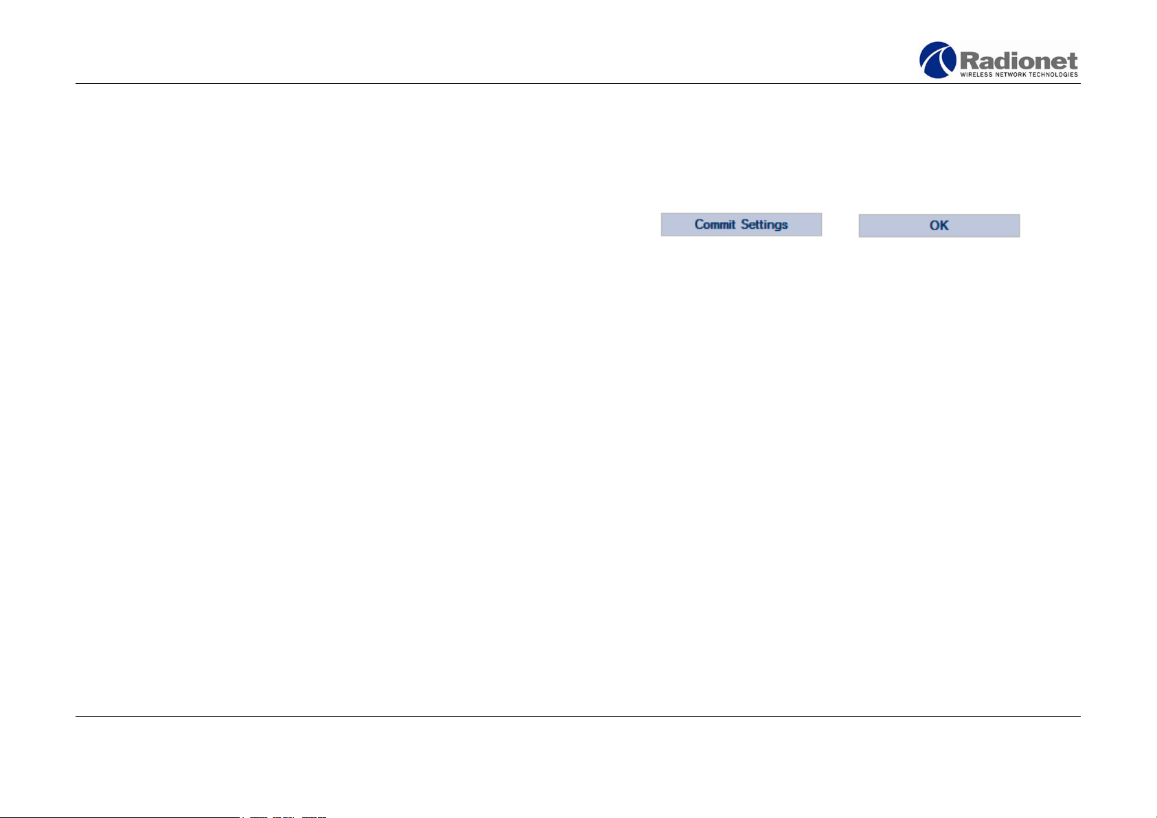
Saving and committing changes
The two action buttons OK and Commit Settings are used to
implement or undo changes to the configuration of the Radionet RN900FCC.
OK
Clicking this button after editing any configuration page will save
the new settings to the Radionet RN-900FCC. The new settings will
not be enabled until Commit Settings button is clicked (see below).
Commit Settings
Click the commit settings button to enable saved settings to persist
after reboot of the Radionet RN-900FCC. The currently saved
settings will be written into the non-volatile memory of the Radionet
RN-900FCC and will be read at each reboot.
Note! To make permanent changes to the configuration of the
Radionet RN-900FCC:
1. Navigate to the appropriate configuration page and enter
2. Click the OK button to accept and apply your changes.
3. Using the menu, navigate to any further pages you wish to
4. When you are satisfied with the configuration of the device,
Figure 4: The action buttons
new settings.
configure and repeat steps (1) and (2).
click the Commit Settings button to permanently record
your changes.
Copyright © Radionet, 2005. All rights reserved.
15 / 48
 Loading...