

Radiometrix RPC3G914RPS User Manual
r
k
d
Hartcran House, 231 Kenton Lane, Harrow, Middlesex, HA3 8RP, England
Tel: +44 (0) 20 8909 9595, Fax: +44 (0) 20 8909 2233, www.radiometrix.com
RPC3G
Issue 4, 1 August 2011
869/914 MHz Radio Packet Controller
Modules: RPC3G-914-64: IC + BiM3G-914-64
RPC3G-869-64: IC + BiM3G-869-64
IC’s: RPC-000-DIL: 18 pin DIL IC
RPC-000-SO: 18 pin SO IC
RPC-000-SS: 20 pin SSOP IC
The RPC3G is an intelligent transceive
modules, which enable a radio network/lin
to be simply implemented between a
number of digital devices. The module
`
combines a BiM3G UHF RF transceiver an
a 64kbps packet controller.
FEATURES
Crystal controlled PLL FM circuitry for both Tx and Rx
Up to 50 meter in-building range, 200m open ground
Built-in self-test / diagnostics / status LED’s
Complies with ETSI EN 300 220-3
Complies with ETSI EN 301 489-3
Single 5V supply @ < 27mA
64kbps half duplex
Free format packets of 1 - 27 bytes
Packet framing and error checking are user transparent
Collision avoidance (listen before transmit)
Direct interface to 5V CMOS logic
Power save mode
INTRODUCTION
The RPC3G is a self-contained plug-on radio port which requires only a simple antenna, 5V supply and a
byte-wide I/O port on a host microcontroller (or bi-directional PC port).
The module provides all the RF circuits and processor intensive low level packet formatting and packet
recovery functions required to inter-connect an number of microcontrollers in a radio network.
A data packet of 1 to 27 bytes downloaded by a Host microcontroller into the RPC3G's packet buffer is
transmitted by the RPC3G’s transceiver and will "appear" in the receive buffer of all the RPC3G's within
radio range.
A data packet received by the RPC3G’s transceiver is decoded, stored in a packet buffer and the Host
microcontroller signalled that a valid packet is waiting to be uploaded.
RF specifications are provided on BiM3G-869-64, BiM3G-914-64 RF transceiver datasheet.
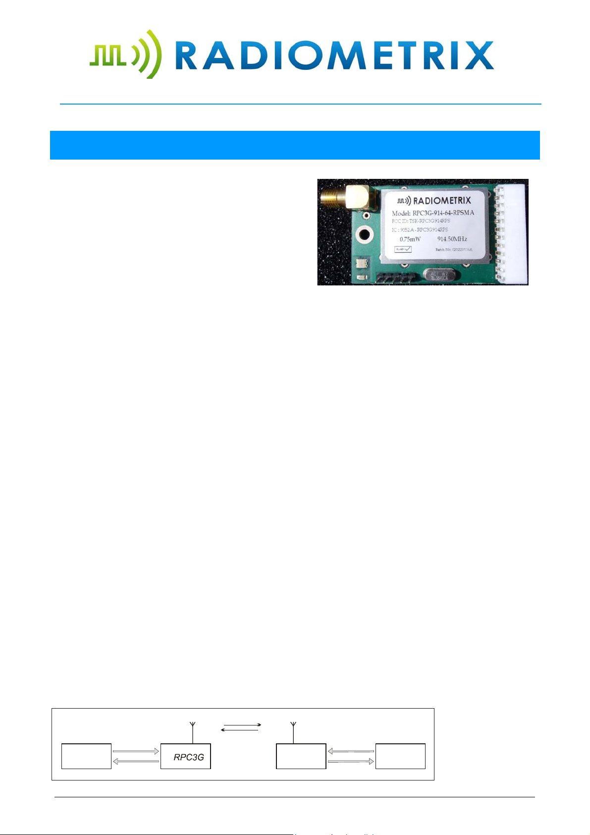
RPC3G-914-64-RPSMA module
transmit / receive
download
HOST
upload
figure 1: RPC3G + Host
Radiometrix Ltd, RPC3G page 1
-controller
RPC3G
download
HOST
upload
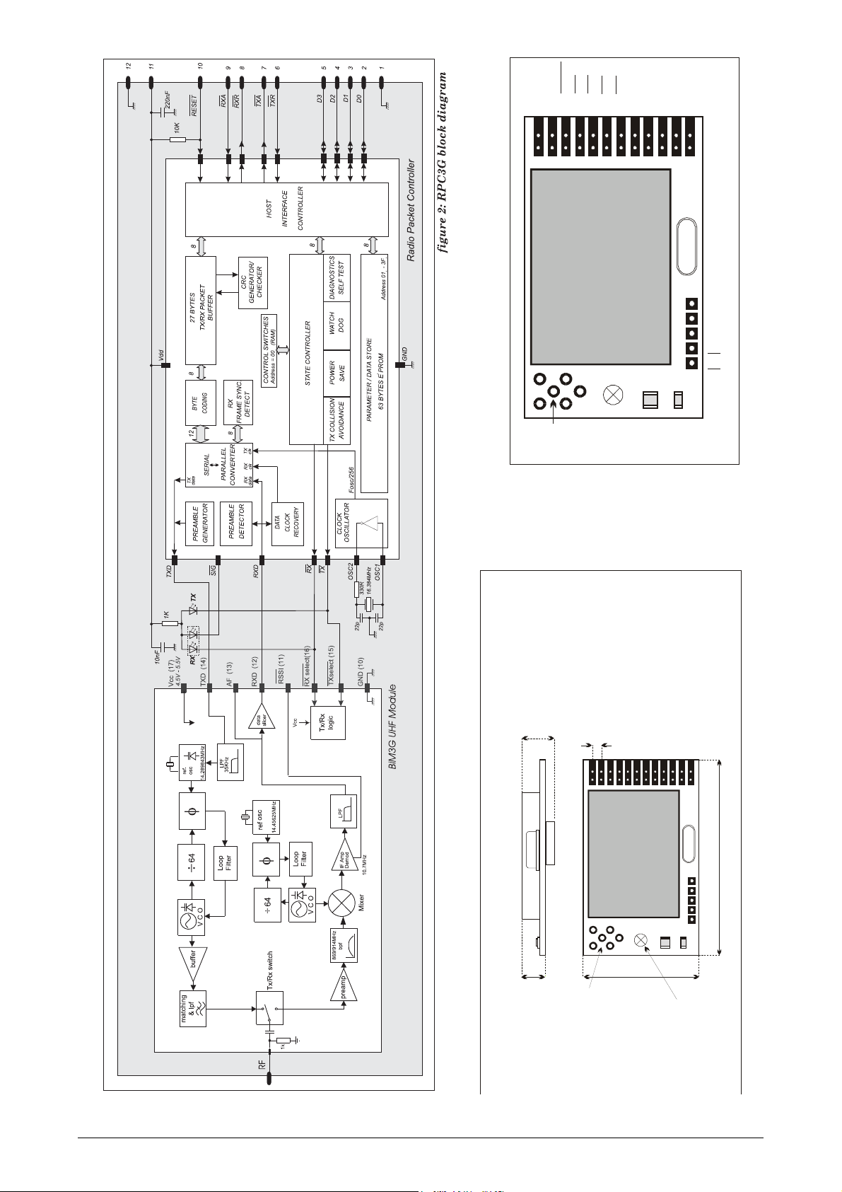
f
g
p
y
9 RXA
8 RXR
7 TXA
6 TXR
5 D3
4 D2
3 D1
2 D0
12 GND
11 Vcc
10 RESET
1 GND
top view
figure 4: RPC3G’s pinout
16.384
Audio
GND
RXD
RF
BiM3G-914-64
GND
RX LED
RX
TX
TX L ED
sical dimensions
h
ure 3:
9.7mm
2.54mm
0.1inch pitch connector
pads suitable for pin headers,
pin sockets, edge connectors
and ribbon cables
16.384
i
54mm
BiM3G-914-64
7.3mm
32mm
3.5mm
mounting
hole
antenna pads for
terminal bloc k
or SMB connector
Radiometrix Ltd, RPC3G page 2

1. FUNCTIONAL DESCRIPTION
On receipt of a packet downloaded by the Host, the RPC3G will append to the packet: Preamble, start byte
and a error check code. The packet is then coded for security and mark:space balance and transmitted
through the BiM3G RF Transceiver as a 64kbps synchronous stream. One of four methods of collision
avoidance (listen before TX) may be user selected.
When not in transmit mode, the RPC3G continuously searches the radio noise for valid preamble. On
detection of preamble, the RPC3G synchronises to the in-coming data stream, decodes the data and
validates the check sum. The Host is then signalled that a valid packet is waiting to be unloaded. The format
of the packet is entirely of the users determination except the 1st byte (the Control Byte) which must specify
the packet type (control or data) and the packet size. A valid received packet is presented back to the host in
exactly the same form as it was given.
To preserve versatility, the RPC3G does not generate routing information (i.e.
source/ destination addresses) nor does it handshake packets. These network
specific functions should be performed by the host.
Additional features of the RPC3G include extensive diagnostic/debug functions for evaluation and debugging
of the radio and host driver software, a built in self test function and a sleep mode / wake-up mechanism
which may be programmed to reduce the average current to less than 100A. The operating parameters are
fully programmable by the host and held in EEPROM, the host may also use the EEPROM as a general
purpose non-volatile store for addresses , routing information etc.
1.1 O
PERATING STATES
The RPC3G has four normal operating states:
I
DLE / SLEEP
HOST TRANSFER
TRANSMIT
RECEIVE
DLE/SLEEP
I
The I
DLE state is the quiescent/rest state of the RPC3G. In IDLE the RPC3G enables the receiver and
continuously searches the radio noise for message preamble. If the power saving modes have been
enabled the RPC3G will pulse the receiver on, check for preamble and go back to S
is found. The 'ON' time is 5ms, OFF time is programmable in the RPC3G’s EEPROM and can vary
between 22ms and 2.9s. The TX Request line from the Host is constantly monitored and will be
acted upon if found active (low). A TX Request will immediately wake the RPC3G up from S
mode.
OST TRANSFERS
H
If the host sets the TX Request line low a data transfer from the Host to the RPC3G will be initiated.
Similarly the RPC3G will pull RX Request low when it requires to transfer data to the Host (this may
polled or used to generate a Host interrupt).
The transfer protocol is fully asynchronous, i.e. the host may service another interrupt and then
continue with the RPC3G transfer. It is desirable that all transfers are completed quickly since the
radio transceiver is disabled until the Host <> RPC3G transfer is completed. Typically a fast host can
transfer a 27 byte packet to / from the RPC3G in under 1ms.
RANSMIT
T
On receipt of a data packet from the host, the RPC3G will append to the packet - preamble, frame
sync byte and an error check sum. The packet is then coded for mark:space balance and
transmitted. A full 27 byte packet is transmitted in 8.1ms of TX air time (64kb/s + 5ms preamble).
Collision avoidance (Listen Before Transmit-LBT) functions can be enabled to prevent loss of
packets.
Data packets may be sent with either normal or extended preamble. Extended preamble is used if
the remote RPC3G is in power save mode. Extended preamble length can be changed in the
EEPROM memory.
ECEIVE
R
On detection of preamble from the radio receiver, the RPC3G will phase lock, decode and error
check the incoming synchronous data stream and if successful. The data is then placed in a buffer
and the RX Request line is pulled low to signal to the host that a valid packet awaits to be uploaded
to the Host.
An in-coming data packet is presented back to the host in the same form as it was given.
LEEP if nothing
LEEP
Radiometrix Ltd, RPC3G page 3
2. THE HOST INTERFACE
2.1 SIGNALS
It is recommended that the RPC3G be assigned to a byte wide bi-directional I/O port on the host processor.
The port must be such that the 4 data lines can be direction controlled without affecting the 4 handshake
line.
pin
name
TXR
TXA
RXR
RXA
D0
D1
D2
D3
Notes: 1. The 4 Handshake lines are active low
2. The 4 Data lines true data
3. Logic levels are 5V CMOS, see electrical specifications
4. Input pins have a weak pull-up internally
Processor
pin
number
pin
function
I/O description
6 TX Request I/P Data transfer request from HOST to RPC3G
7 TX Accept O/P Data accept handshake back to HOST
8 RX Request O/P Data transfer request from RPC3G to HOST
9 RX Accept I/P Data accept handshake back to RPC3G
2 Data 0 (4) Bi-dir 4 bit bi-directional data bus. Tri-state
3 Data 1 (5) Bi-dir between packet transfers, Driven on
4 Data 2 (6) Bi-dir receipt for Accept signal until packet
5 Data 3 (7) Bi-dir transfer is complete.
R
ESET
The Reset signal, may either be driven by the host (recommended) or pulled up to Vcc via a suitable
resistor (10k). A reset aborts any transfers in progress and restarts the Packet Controller.
H
OST DRIVEN RESET
Minimum low time: 1.0 s, after reset is released (returned high). The host should allow a delay 1ms
after reset for the RPC3G to initialise itself
During this delay the host must hold TXR high (unless D
IAGNOSTIC MODES are required) and RXR
signal should be ignored.
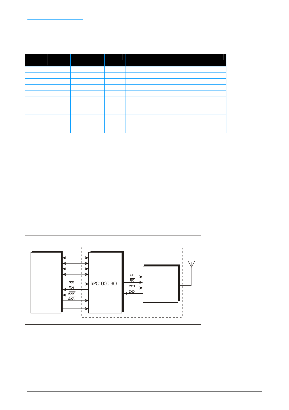
RPC3G-914-64
D0
D1
D2
D3
Host
BiM3G-914-64
Transceiver
RESET
figure 5: Host to RPC3G connection
Radiometrix Ltd, RPC3G page 4
2.1.1 HOST TO RPC3G DATA TRANSFER
Data is transferred between the RPC3G and the H
OST 4 bits (nibbles) at a time using a fully asynchronous
protocol. The nibbles are always sent in pairs to form a byte, the Least Significant Nibble (bits 0 to 3) is
transferred first, followed by the Most Significant Nibble (bits 4 to 7). Two pairs of handshake lines, R
EQUEST
& ACCEPT, control the flow of data in each direction:-
TX Request & TX Accept: control the flow from the HOST to the RPC3G (download)
RX Request & RX Accept: control the flow from the RPC3G to the HOST (upload)
A packet transferred between host and RPC3G consists of between 1 and 28 bytes, the first byte of the
packet is always the control byte.
There are two classes of H
OST RPC3G transfers:
1. Data Packets: To the transmitter or from the receiver
2. Memory Access: To or from the RPC3G's memory
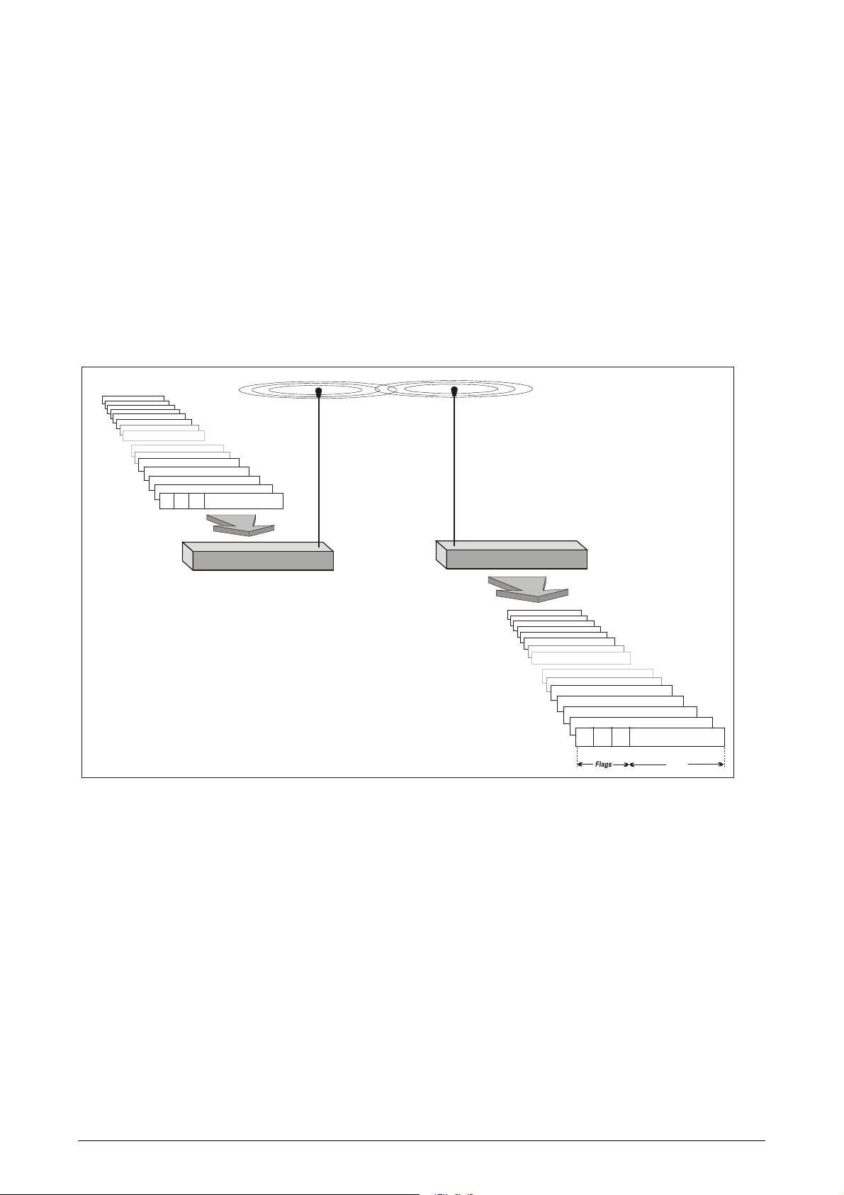
Byte Count (1-27)
000
Packet To Transmit
RPC3G
figure 6: RPC3G Host data transfer
Received Packet
RPC3G
rd
3 data byte
nd
2 data byte
st
1 data byte
control byte
00
Byte Co unt (1-2 7 )
0
5 bits
0657
Radiometrix Ltd, RPC3G page 5
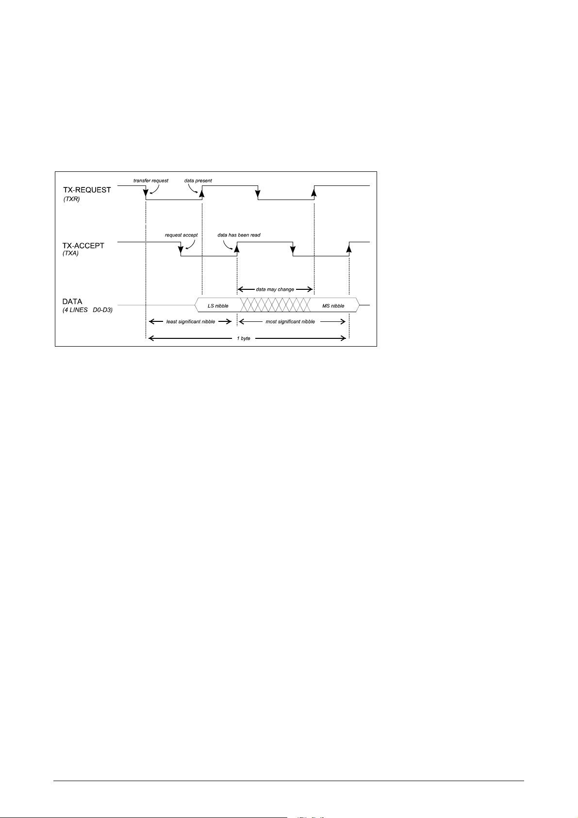
2.1.2 WRITE A BYTE TO RPC3G
The sequence for a byte transfer from the Host to the RPC3G (i.e. TX download) is asynchronous and
proceeds as follows:
1. HOST asserts TX Request line low to initiate transfer
2. Wait for RPC3G to pull TX Accept low (i.e. request is accepted)
3. Set data lines to output and place LS nibble on the data lines
4. Negate TX Request (set to 1) to tell RPC3G that data is present.
5. Wait for RPC3G to negate TX Accept (i.e. data has been accepted)
Repeat steps 1-5 with MS nibble.
figure 7: TX download timing diagram
Notes:
The data bus must not be set to output until step 3. i.e. after the RPC3G has accepted the request. The
bus may be left as an output until the entire packet has been transferred to the RPC3G, it should then be
set back to input (default state).
The RPC3G's normal response time to the initial TX Request may be up to 1ms, thereafter, for the
duration of the packet, the response will be fast.
The RPC3G will ignore a TX Request from the Host while it is receiving a packet from the radio. If the
incoming packet fails it's error check the RPC3G will respond to the TX Request as normal, i.e. the TX
Accept from the RPC3G will be delayed until the incoming packet has finished. If a valid packet is
received this must be uploaded to the Host before the RPC3G can respond to the Host’s TX Request.
Thus an RX Request will be signalled to the Host and not the expected TX Accept and the Host must
upload the incoming packet before the TX packet can be downloaded. The TX Request should be left
asserted (low) during the upload. The RPC3G will respond as normal after the upload is completed.
For the above reason it is often easier to use RX Request to trigger a HOST interrupt and upload the
RPC3G to the HOST under interrupt control.
See Appendix B and C. for example RPC3G driver subroutines.
Radiometrix Ltd, RPC3G page 6
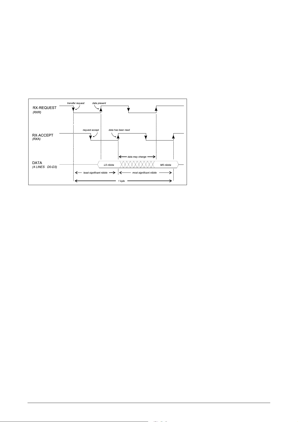
2.1.3 READ A BYTE FROM THE RPC3G
The sequence for a byte transfer from the RPC3G to the HOST (i.e. RX upload) is asynchronous and
proceeds as follows :-
1. RPC3G will assert RX Request line low to initiate transfer
2. Host pulls RX Accept low (i.e. request is accepted by the host)
3. RPC3G will turn on it's bus drivers, place LS nibble onto data lines
and negate RX Request (set to 1)
4. Host reads the data and negates RX Accept (i.e. data has been accepted)
Repeat steps 1-4 with MS nibble.
figure 8: RX upload timing diagram
Notes:
The RPC3G will turn off it's data bus drivers after the entire packet has been uploaded to the HOST.
See Appendix B and C. for example RPC3G driver subroutines.
2.2 HOST <> RPC3G PACKET FORMAT
2.2.1 T
The first byte of a RPC3G <> HOST packet transfer is always the C
the transfer and contains information about the type of packet, number of bytes to be transferred, memory
address, read/write bit etc. Bit 7 of the control byte is the Packet Type flag, PT, it determines the class of
transfer and the interpretation of the other bits in the control byte.
HE CONTROL BYTE
ONTROL BYTE. This byte is used to control
Radiometrix Ltd, RPC3G page 7
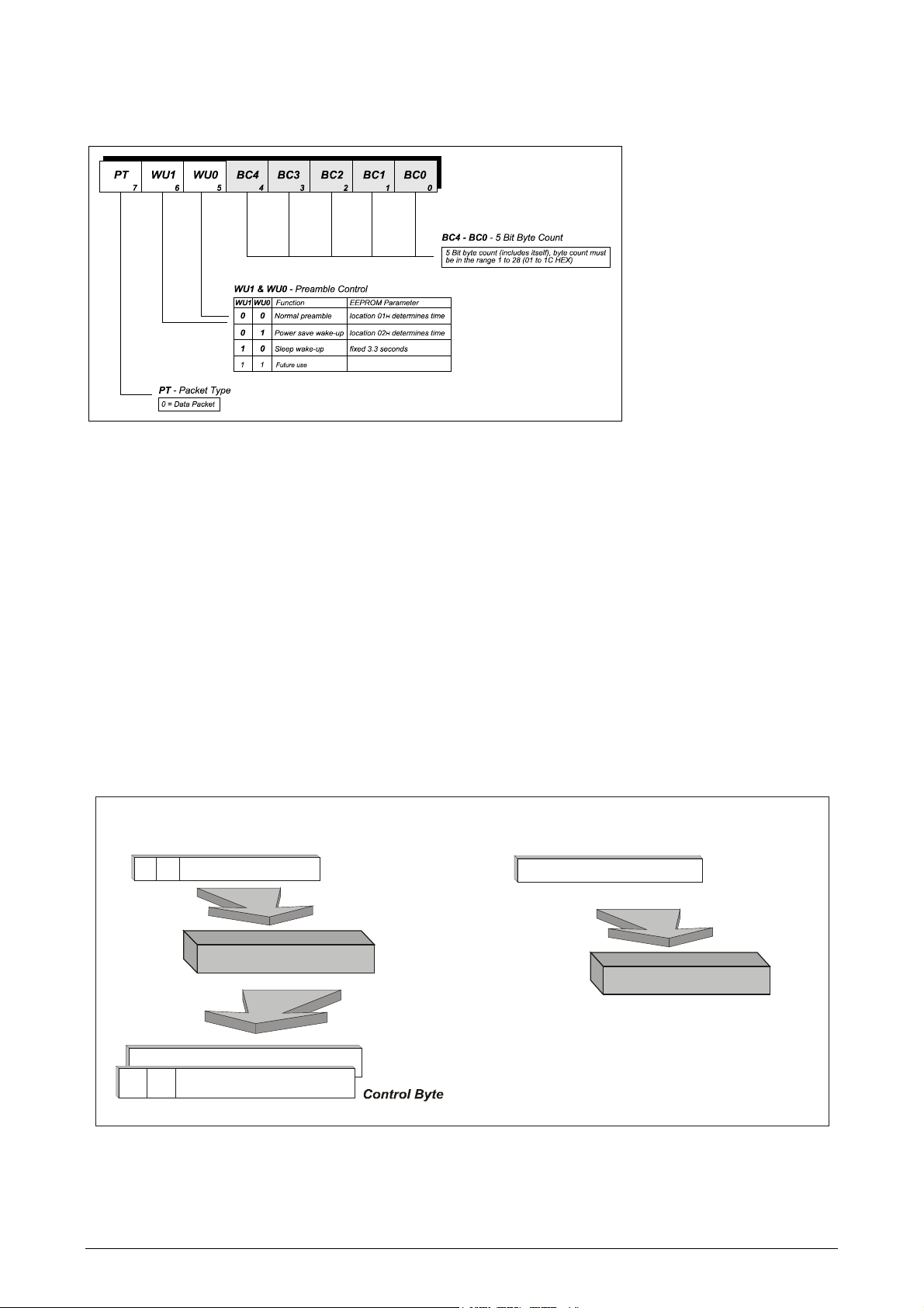
2.2.2 SENDING AND RECEIVING DATA PACKETS
f
Data packets are sent to / received from remote RPC3G’s. They begin with a control byte with bit 7 cleared
and may be of variable length and contain up to 27 bytes of user determined data.
figure 9: Control byte for data packet
The remainder of the bytes in the data packet are of the users determination.
The packet would usually be made up of a number of fields consisting of some
but not necessarily all of the following :-
Source address / ID
Destination address / ID
System ID
Packet count
Encryption / Scrambler control
Additional error check codes ( The RPC3G performs it's own error checks)
Routing information ( for repeaters)
Link control codes (connect/disconnect/ACK/NAK etc.)
Data field
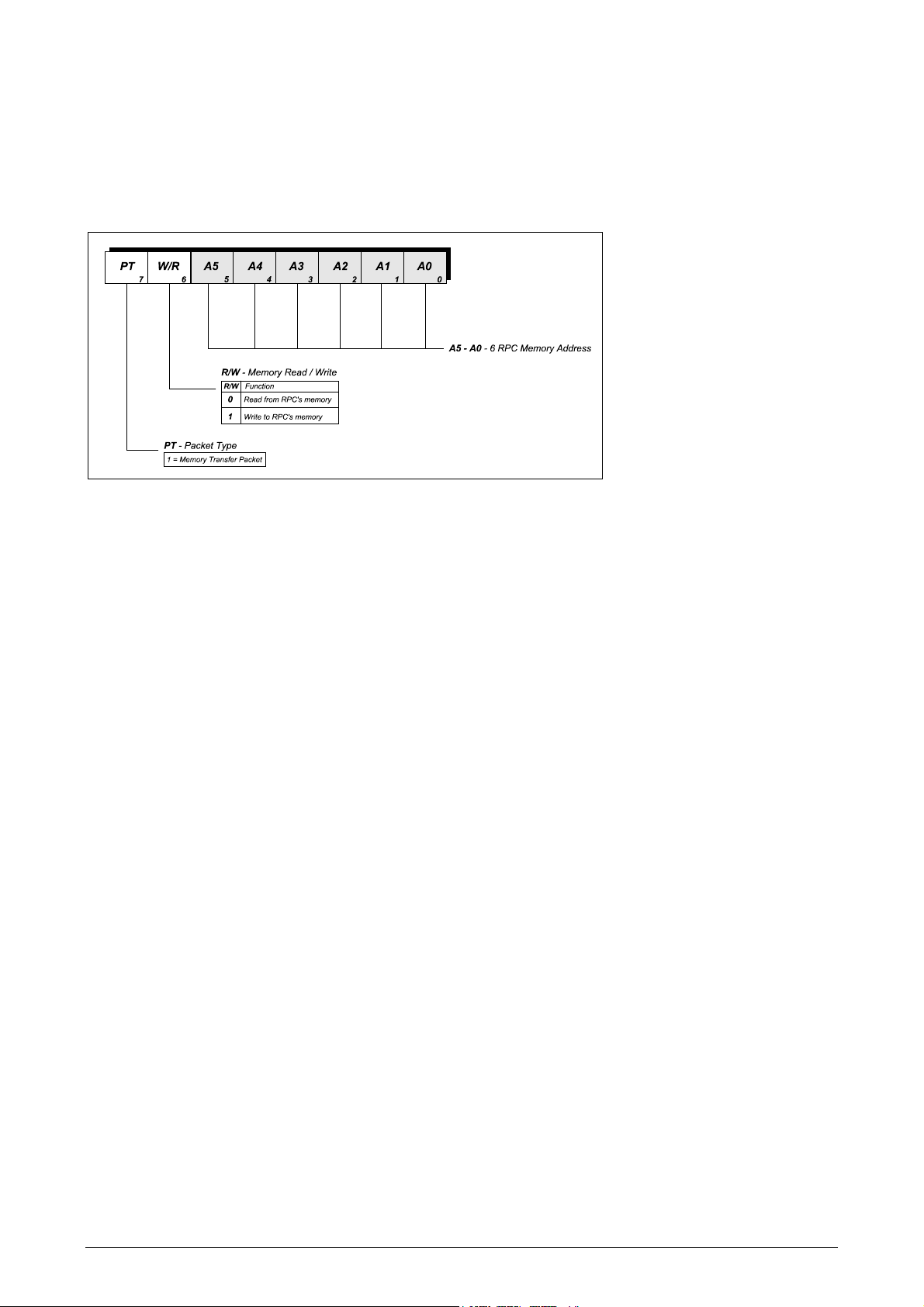
2.2.3 RPC3G M
EMORY ACCESS
The RPC3G’s EEPROM memory can be accessed by setting bit 7 in the control byte. Bit 6 (R/W flag)
defines a memory read or write. The bits left define the address.
Read from memory
10
Address (6 bit)
7
6
Control Byte
0
Write to memory
Data Byte
Control Byte
RPC3G
RPC3G
Data byte
7
10
7
igure 10: RPC3G memory access
Radiometrix Ltd, RPC3G page 8
Address (6 bit)
6
0
0
RPC3G Memory READS:
f
Host issues just the control byte, with bit 6 (W/R) cleared, bit 7 (PT) set and the memory address. The
RPC3G will respond with 2 bytes, the first is a control byte which is an echo of the control byte just issued by
the host, this is useful if the host is using an interrupt handler. The 2nd byte is the memory contents.
RPC3G Memory WRITES:
Host issues 2 bytes, the first is the control byte with bit 6 (W/R) set, bit 7 (PT) set and the memory address.
The 2nd byte is the data to be written. The RPC3G does not give a response to memory writes.
igure 11: Control byte for memory access
Notes Memory writes to locations 01 to 3F, write to the non-volatile EEPROM in the RPC3G. The EEPROM
has a limit of 100,000 write cycles therefor it's use must be restricted to infrequently changed
data. The RPC3G only writes to the EEPROM when instructed to by the HOST. Each byte takes
10ms to write. To prevent accidental/spurious writes to EEPROM the host must set the WE bit in
SWITCHES prior to EACH byte to be written. We recommend that the host performs a read/verify
after each byte write to EEPROM.
The above does not apply to any memory reads nor to writes to SWITCHES (address 00h).
Radiometrix Ltd, RPC3G page 9
 Loading...