


RADIOLINK T8FB
(FHSS)
INSTRUCTION MANUAL
8CH remote control system
RADIOLINK ELETRONIC LIMITED
Technical updates and additional programming examples available at:
www. radiolink.com

1
INTRODUCTION
Thank you for purchasing Radiolink 2.4 GHz 8 channels remote control system -- T8FB .
It can operate helicopter, fixed-wing, glider, aircraft models. Communication system adopts
FHSS. Parameter setting designed applicable to both beginners and skilled person. In order to
better use remote control equipment and ensure flight safety, please read the instructions
carefully.
Suggestion: when you read this manual, please turn on the transmitter and receiver, connect
T8FB to computer with special Radiolink upgrade cable, connect the receiver to gyro and
other related equipment, operating while reading. Please refer to the manual or call our
after-sales (+86-0755-88361717) or login BBS (such as www.rcgroups.com, www.5imx.com)
to check the issues related answer to questions if you have any questions.
Due to unforeseen changes in production procedures, the information contained in this
manual is subject to change without notice.
More information please check our website as below:
http://www.radiolink.com
Support and Service: It is recommended to have your Radiolink equipment serviced annually
during your hobby’s “off season” to ensure safe operation.
Please feel free to browse our GUEST BOOK for assistance in operation, use and
programming. Please be sure to regularly visit the Service and Support web site at
www.radiolink.com. This page includes extensive programming, use, set up and safety
information on the T8FB radio system and is updated regularly.
Any technical updates and manual corrections will be available on this web pages.If you do
not find the answers to your questions there, please see the end of our contact area for
information on contacting us via email for the most rapid and convenient response.
FOR AFTER-SALES SERVICE:
Please start here for getting more service.
www.radiolink.com
Phone:+86-755-88361717
Email:after_service@radiolink.com.cn
FOR TECHNIQUE SUPPORT:
Please start here for answers to technique questions:
www.radiolink.com
Phone:86-755-88361717
Email:alice@radiolink.com.cn

2
Note:About flying
While you are getting ready to fly, if you place your transmitter on the ground ,be sure that
the wind won’t tip it over. If it is knocked over, the throttle stick may be accidentally moved,
causing the engine to speed up. Also, damage to your transmitter may occur.
Other than 2.4GHz system: Before operating, be sure to extend the transmitter antenna to its
full length, collapsed antenna will reduce your flying range and cause a loss of control.It is a
good idea to avoid pointing the transmitter antenna directly at the model, since the signal is
weakest in that direction.
In order to maintain complete control of your aircraft it is important that it remains visible at
all times .
Flying behind large objects such as buildings, grain bins, etc. are not suggested. Doing so may
result in the reduction of the quality of the radio frequency link to the model.
2.4GHz system: Do not grasp the transmitter module’s antenna during flight.Doing so may
degrade the quality of the radio frequency transmission.
2.4GHz system: As with all radio frequency transmissions, the strongest area of signal
transmission is from the sides of the 8CH transmitter module's antenna. As such, the antenna
should not be pointed directly at the model.If your flying style creates this situation,easily
move the antenna to correct this situation.
Warning!!!
Please don't fly in the rain! Water or moisture may enter the transmitter internal through gaps in the
antenna or joystick flight and cause your flight to instability even out of control. If inevitable will fly in
the wet weather (such as game), please be sure to use plastic bags or waterproof cloth to cover your
transmitter, please don't flight if there is lightning.
FCC Statement
This equipment has been tested and found to comply with the limits for a Class B digital device, pursuant
to Part 15 of the FCC Rules. These limits are designed to provide reasonable protection against harmful
interference in a residential installation. This equipment generates uses and can radiate radio frequency
energy and, if not installed and used in accordance with the instructions, may cause harmful interference
to radio communications. However, there is no guarantee that interference will not occur in a particular
installation. If this equipment does cause harmful interference to radio or television reception, which can
be determined by turning the equipment off and on, the user is encouraged to try to correct the
interference by one or more of the following measures:
-- Reorient or relocate the receiving antenna.
-- Increase the separation between the equipment and receiver.
-- Connect the equipment into an outlet on a circuit different from that to which the receiver is connected.
-- Consult the dealer or an experienced radio/TV technician for help.
Changes or modifications not expressly approved by the party responsible for compliance could void the
user's authority to operate the equipment.

3
CONTENTS
Part 1. INTRODUCTION OF T8FB SYSTEM...................................................... 4
1.2.1 Transmitter.................................................................................................... 5
1.2.2 Receiver:R8EH............................................................................................. 5
1.2.3 Bind............................................................................................................... 5
1.2.4 S-BUS, PPM and PPM signal change........................................................... 6
1.2.5 Transmitter calibration .................................................................................. 6
PART 2. Firmware Upgrade or Model Type Change...............................................9
PART 3.Parameter configuration.............................................................................13
1.1 Transmitter Panel Shows..................................................................................... 4
1.2 T8FB remote control system............................................................................... 5
1.3 Guidelines to mount the servos, receiver and battery............................................7
2.1 Preparation............................................................................................................13
2.2 Software description.............................................................................................14
4
Part 1 INTRODUCTION OF T8FB SYSTEM
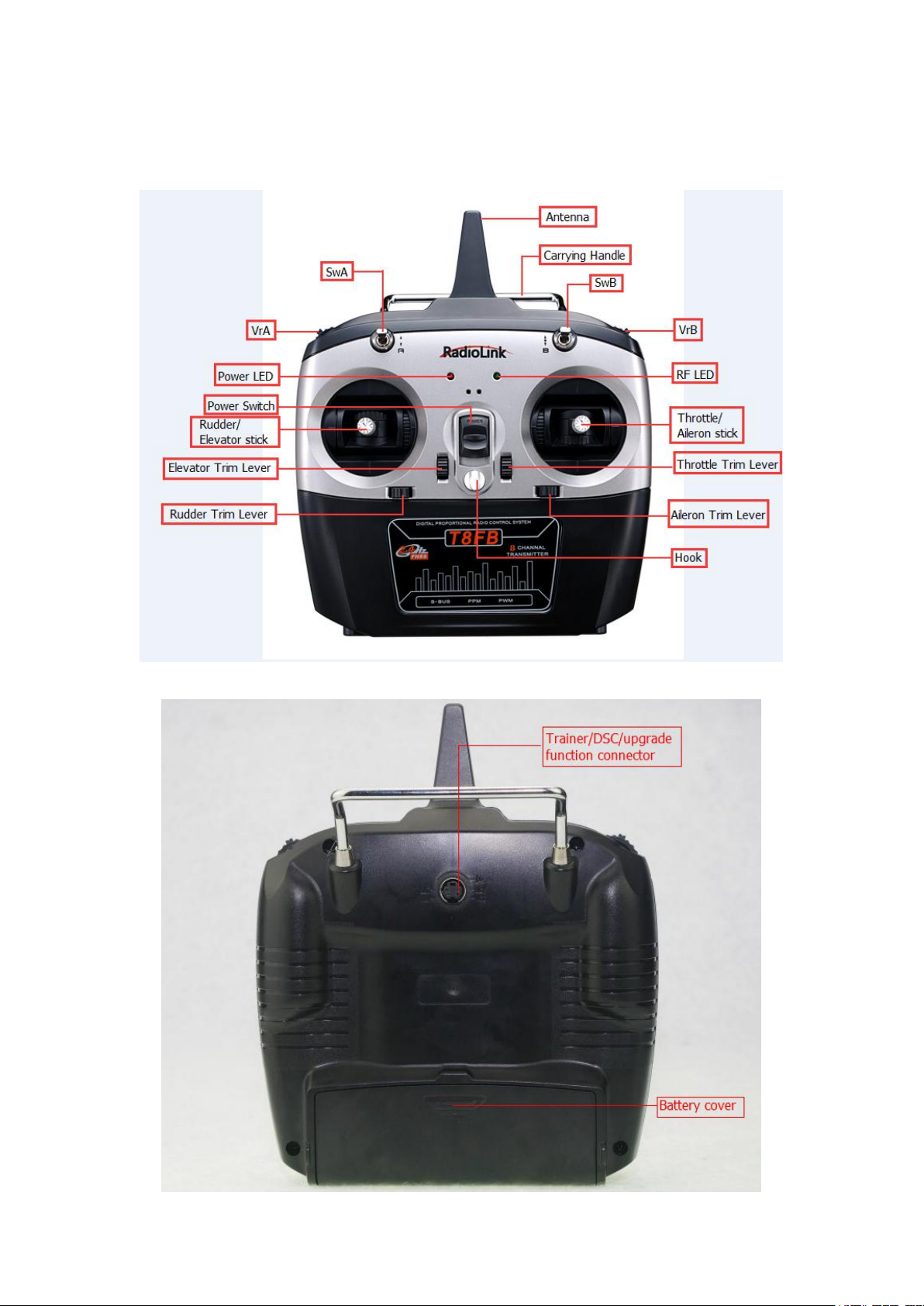
1.1 Transmitter Panel Shows:
5
1.2 T8FB remote control system
1. S-BUS/PPM/PWM
2. Operating voltage: 4.8~10V.
3. Operating current: 19~25mA(input voltage 5V)
4. Size: 48.5*21*11mm
5. Weight: 7g
6. Section precision: 4096
1.2.1 Transmitter
1) One two-way switch, one three-way switch, two VR switches, four trimmers, two sticks.
2) Defaulted MODE2, SwB control CH5, VrB control CH6, SwA control CH7, VrA control
CH8.
3) Defaulted low battery alarm voltage is 11.1V, can setting in the T8FB configure software.
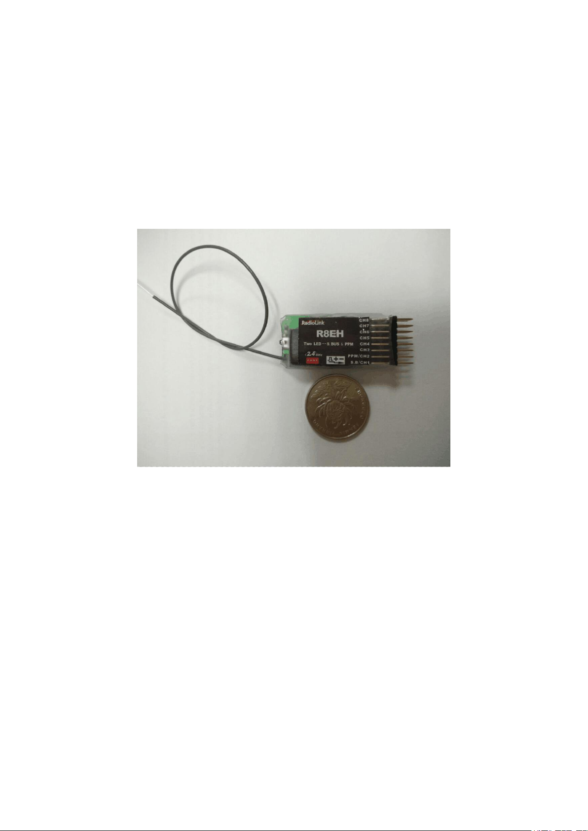
1.2.2 Receiver: R8EH
R8EH: 8 channel receiver support S-BUS, PPM and PWM signal at the same time.
8 channel receiver R8EH(signal type: PWM&S-BUS&PPM)
R8EH Specification:
Compatible with FUTABA S-BUS connection port, S-BUS, PPM and PWM signal are possible to
use at the same time.
PWM signal mode: Green LED, output 8 channel PWM signal.
SBUS/PPM signal mode: Both red and green LED on, CH1 output S-BUS signal, CH2 output
PPM signal, CH3 to CH8 output PWM signal at the same time.
1.2.3 Bind
Each transmitter has an individually assigned, unique ID code. In order to start operation,
the receiver must be linked with the ID code of the transmitter with which it is being paired.

6
Once the link is made, the ID code is stored in the receiver and no further linking is necessary
1) Place the transmitter and the receiver close to each other within 1 meter.
2) Connect CH3(R8EH) to ESC.
3) Press and hold ID SET switch of the receiver one second, now the indicator LED will
4) Test with servo to make sure the binding is finished.
2) Center position calibration:
• Make certain the alignment tab on the battery, switch and servo connectors is orient
correctly and ‘key’ into the corresponding notch in the receiver or connectors before plugging
them in.When unplugging connectors, never pull on the wires. Always pull on the plastic
connector instead.
• Receiver’s Antenna: In generally receiver’s antenna is longer than remote control,don’t
break or retract it,otherwise shorten the control distance.The antenna must be kept away from
conductive materials,such as metal. Please make distance test before flying.
•If your aileron servos are too far away to plug into the receiver,use an aileron extension cord
unless the receiver is to be used with another transmitter. When you purchase another R8EH,
this procedure is necessary; otherwise the receiver will not work.
starting blinking. It will automatically find the nearest transmitter to bind.
1.2.4 S-BUS, PPM and PPM signal change
Short press the ID SET switch two times within 1 second, the signal is changed from normal
PWM to S-BUS or PPM. The green LED indicates the normal PWM and red&green LED
indicates S-BUS or PPM signal.
1.2.5 Transmitter calibration:
1. Press rudder trimmer left and turn on transmitter at the same time, red and green LED
flashing.
1) End point calibration:
Push two sticks from the highest position to the lowest position, and then put sticks to the
center position. (P1)
(P1)
Put stick to the center position, press rudder trimmer right, and then red and green LED always on
means sticks calibrate successful.
1.3 Guidelines to mount the servos, receiver and battery

7
to extend the length. Avoid plugging multiple extensions together to obtain your desired
length. If the distance is greater than 50cm or high current draw servos are being used, use
heavy servo extensions.
• Receiver Vibration and Waterproofing: the receiver contains precision electronic part.Be
sure to avoid vibration,shock,and temperature extremes.For protection, wrap the receiver in
foam rubber or other vibration-absorbing materials. It is also a good idea to waterproof the
receiver by placing it in a plastic bag and securing the open end of the bag with a rubber band
before wrapping it with foam rubber. If you accidentally get moisture or fuel inside the
receiver,you may experience intermittent operation or a crash. If in doubt, please contact
Radiolink after-sales or distributors for service.
• Always mount the servos with the supplied rubber grommets. Don’t over tighten the screws.
No part of the servo casing should contact the mounting rails, servo tray or any part of
structure. Otherwise vibration will be transmitted to the servo causing damage of servo. Note
the small numbers (1,2,3,4) molded into each arm on the servo arms. The number indicate
how many degrees each arm is ‘off’ from 90 degrees to correct for minute manufacturing
deviations from servo to servo.
To center the servos, connect them to receiver and turn on the transmitter and receiver. Center
After the servos are installed, operate each servo over its full travel and check that the push
rods and servo arms don’t bind or contact each other. Also make sure the controls do not
require excess force to operate. If there is an objectionable buzzing sound coming from a
servo, there is probably too much resistance in the control. Find and correct the problem.
Even there is no servo damage, excess battery drain will result.
•Use the mouthing plate from the receiver on/off switch as a template for the cutout and screw
holes, mount the switch on the side of the fuselage opposite the engine exhaust, and where it
won’t be inadvertently turned on or off during handling or storage. Be certain the switch
moves without restriction and ‘snaps’ from ON to OFF, and that the cutout allows full motion
the trims on the transmitter, then find the arm that will be perpendicular to the push rod when
placed on the servo.

8
of the switch in both directions.
•When install the switch harness to the helicopter, please use the switch cover. Generally
sandwich the frame between the switch and switch cover and securely tighten the screws.
Different models might require different installations. If so, please follow the model’s
instruction manual.
• To prevent the servo lead wires from being broken by vibration during flight, provide a
slight amount of slack or extra so that the wire sticks out slightly and fasten it at suitable
points. In addition, periodically check the wire during daily maintenance.
Upgrade/firmware version change/parameter setting cable
1. Install the T8FB upgrade drive files first.
2. Connection: One end of T8FB USB cable connect to computer and the other end connect to the
upgrade port which at the back of T8FB.
T8FB upgrade connector connection:
TXD connect to white wire, RXD connect to red wire, GND connect to black wire.
OR
TXD connect to white wire, RXD connect to green wire, GND connect to black wire.

9
Part 2 Firmware Upgrade or Model Type Change
1. Open file “T8FB”.
2. Choose COM, and click “Connect” and then turn on T8FB in 1 second.

10
3. “Disconnect” will change to “Connected” and the color of word will from red to green if
connect successful.

11
4. Choose “APROM” and then choose the firmware you need, for example, firmware for
multicoptor.

12
5. Click “Start”, the progress bar will turn to green, upgrade successful if remind “PASS”.

13
Part 3 Parameter Configuration
(P2)
2.1 Preparation
1. Install the drive for the parameter configuration software.
Open T8FB parameter configuration software.(P2)

14
2. Choose Port Number(T8FB connection COM will automatic identified when connect to
computer), setting baud rate: 115200, 8-1-None(8 data bits,1 stop bit,no parity check),click
“CONNECT”.(P3)
(P3)
2.2 Software description
“READ”:
Computer will read data from transmitter and show on the computer when click “READ”(red
and green LED will quick flashing when reading).
“LOAD”:
Load configured TXT files.
“UPDATE”:
Write down the new data you want and then click “UPDATE” to change the defaulted
parameter. T8FB will remember the new data you have write down(red and green LED will
slowly flashing when updating).
“SAVE”:
Save current setting to TXT files.
“PHASE”:
Changes the direction an individual servo responds to a control stick motion.
“SUB-TRIM”:
Makes small changes or corrections to the neutral position of each servo. Range is -120 to
+120, with 0 setting, the default, being no SUB-TRIM.
We recommend that you center the digital trims before making SUB-TRIM changes, and that

15
you try to keep all of the SUB-TRIM values as small as possible. Otherwise, when the
SUB-TRIM are large values, the servo's range of travel is restricted on one side.
The recommended procedure is as follows:
• Measure and record the desired surface position;
• Zero out both the trims (TRIM RESET menu) and the SUB-TRIM (this menu);
• Mount servo arms and linkages so that the control surface’s neutral is as correct as possible;
•use a small amount of SUB-TRIM to make fine corrections.
“END POINT”:
Sets the range of each channel(in percentage);
End Point of servo travel adjustment (END POINT, also called EPA)
The most flexible version of travel adjustment is available. It independently adjusts each end
of each individual servo’s travel, rather than one setting for the servo affecting both
directions.
Adjustability:
• Can set each direction independently.
• Ranges from 0% (no servo movement at all) to 140%. Defaulted 96%.
•Reducing the percentage settings reduces the total servo throw in that direction.
END POINT adjusts only the individual servo. It will have no effect on any other servo that is
operated in conjunction with this servo via mix or preset programming such as FLAPERON,
AILEVATOR, etc. This is so that each individual servo can be carefully fine-turn to avoid
binding and other conflicts. To adjust the total travel of a function such as FLAPERON, make
the adjustments in that function's controls.
The higher the END POINT setting, the better position accuracy and the more servo power
available at nearly any position (except if using digital servos). Higher END POINT values
also mean longer travel time to reach the desired position, as you are utilizing more of the
servo's total travel. (For example, using 50% END POINT would give you only half the steps
of servo travel, meaning every click of trim has twice the effect and the servo gets there in
half the time).
• END POINT(and moving the linkage) = torque, accuracy, but transit time to get there.
• END POINT (instead of adjusting linkages) = travel time, but torque, accuracy.
“FAIL SAFE”:
F/S data,set responses in case of loss of signal or low Rx voltage(in percentage).
Each channel can be set independently.
• The NOR (normal) setting holds the servo in its last commanded position.
• The F/S (Fail Safe) function moves each servo to a predetermined position.
• NOTE: the setting of the throttle's F/S also applies to the low battery voltage.
• The F/S is used in certain competitions to spin the aircraft to the ground prior to flying away
and doing potential damage elsewhere. Conversely, may also be used to go to neutral on all
servos, hopefully keeping the plane flying as long as possible.
0 means throttle at the lowest position, 50 at the center position.

16
“AUX-CH”:
Defines the relationship between the transmitter controls and the receiver output for channels
5-8.
“TX-ALARM”:
Setting transmitter alarm voltage(defaulted 11.1 V).
“STK-MODE”:
Change the mapping relation among sticks(MODE1 means throttle is the right stick; MODE2
means throttle is the left stick).
 Loading...