

Digital 3-Channel Proportional RC System
Instruction Manual
RadioLink Electronics Co., Ltd
Http://www.radiolink.com.cn
CE FCC ROHS

MENU
1. Introduction and service………………………………………………………….2
2. Safety guides……………………………………………………………….....…. 2
3. Battery recharge notice……………………………………………………..….…3
4. Contents and specifications………………………………………………..…..…. 4
5. Receiver installation and binding………………………………………………… 5
6. Display when power switch turned on…………………………………….……... 6
7. Language Select "LANGUAGE"………………....……………………………......7
8. Model Select "MODEL"………………………………………………...................8
9. End Point Adjuster "EPA"………………………………….…..…..…………...…8
10. Steering EXP "STEXP"…………………………………….………..……………..9
11. Steering Speed "STSPD"……………………………………. .….…………..…...10
12. Throttle EXP "THEXP"…………………………………………………………...11
13. Throttle Speed "THSPD"……………………………………………………….....16
14. A.B.S. Function "A.B.S"…………………………………………………..............18
15. Throttle Acceleration "ACCEL"…………………………………………………...22
16. Idle-Up "IDLUP"…………………………………………………………........….24
17. Subtrim "SUBTR"…………………………………………………………..…….25
18. Servo Reverse "REV"……………………………………………………….....….26
19. Steering Dual Rate/Throttle Dual Rate "D/R"………………………………...……26
20. ATL Function "ATL"………………………………………………………...……27
21. Programmable Mixes "PMIX"………………………………………………..…....28
22. Channel 3 Position "CH3"………………………………………..……………30
23. Model name "NAME"…………………………………………………….…....32
24. Reset function "RESET"……………………………………………………...…..32
1
Safety guides
Introduction and Service
Thank you for choosing RadioLink RC system, if you are the first time to use
this type of products, please read this statement carefully and strictly in accordance
with the requirements of operation. You could refer to the Manual if you meet any
problems during the operation . Please well keep the manual after use because you
might have to use it again next time.
If you found any problems during the operation process, please refer to the
manual. If the problem still exists, you could contact our dealers to find out the way to
solve it. And you could also log on our website for service:
Http://www.radiolink.com.cn
Important Safety Notice:
The following two symbols will appear in this manual(please pay attention to
the paragraph with this two symbols labeled):
Prohibition Testing and confirmation
Do not use in bad weather such as rainy or thundering to assure the safety of
you and others.
Forbid to use this product in the crowd and the place against national law!
You need to turn the throttle channel(ch3) and inch switch to the lowest
before you use. Then switch on the transmitter, finally connect the receiver.
Before using, please make sure the movements of servo are corresponding
with the direction of joystick. If inconsistent, please adjust them before using.
2

The sequence to shut down is that turn off the receiver power first, and then
Battery recharge notice
shut down the transmitter. If the above operations are reverse, it might lead to
uncontrolled situation and cause accidents
The transmitter needs to be powered by 4 AA alkaline 5# batteries or Ni-MH
batteries. Please check the voltage of batteries before using, as it might lead to
uncontrolled situation and accidents when the voltage is lacked. So you must change
the battery or recharge them in time.
Recharge steps:
A. Install the batteries to transmitter with correct directions, and cover it.
B. Connect the charger to the main connector.
C. Connect the charger to the transmitter charging port.
D. Cut off the power supply immediately while recharging completed.
Warning: Don’t try to charge to one-off dry batteries, avoiding a fire, explosion or
other severe consequence.
If you are using a nickel-cadmium, nickel-metal hydride batteries for recharging,
please use our company dedicated charger(optional accessory). If the electrical
current is too large and it might lead to overheated and cause a burning accident.
Please cut off the power supply immediately after recharging. Please take out the
batteries from the transmitter when you are not using it within a period, because the
battery might damage the battery connection metal flake, thus cause bad connection.
Above safety notices must be complied strictly, our company will not be
responsible for any damage caused by the behaviors forbidden in above notices.
3
Contents and specifications
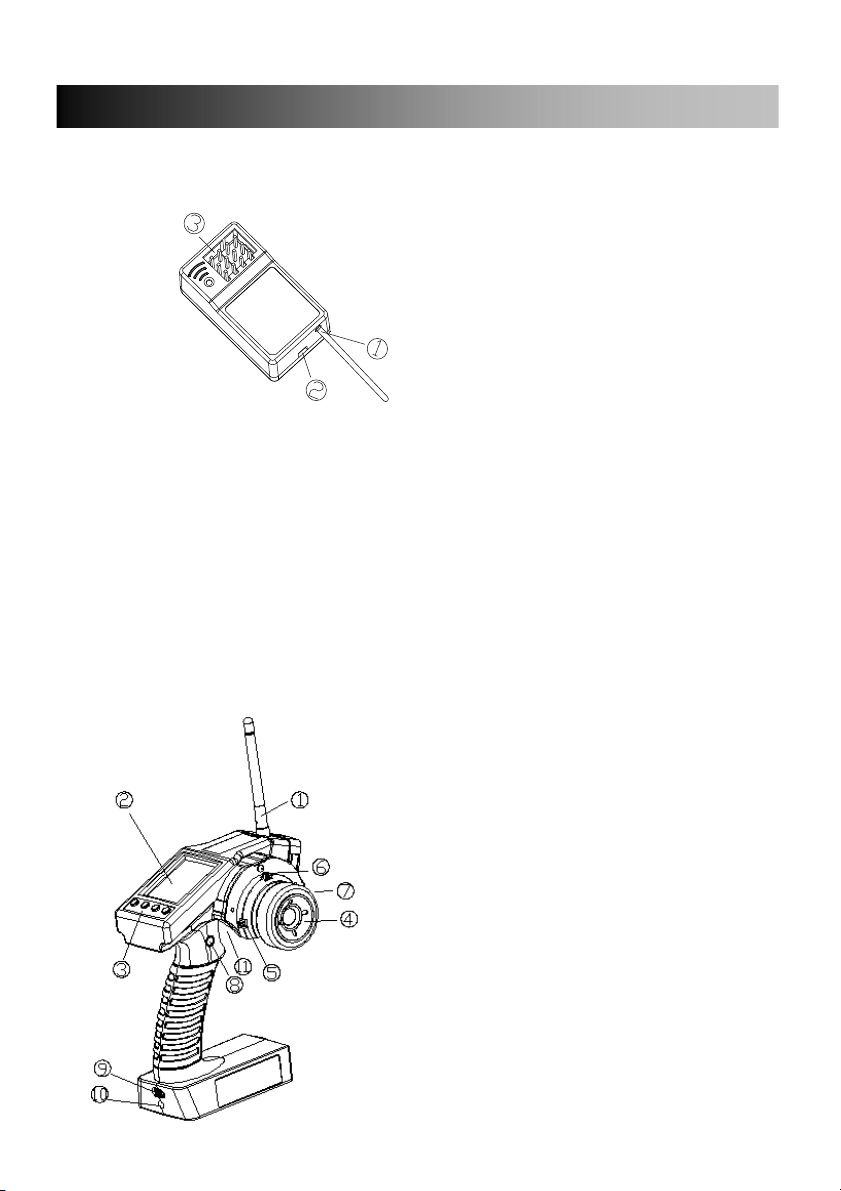
Contents and Specifications:
Contents:
1.Antenna 2.Binding key
3.Channel connection pin
Specs:
Size:51.5*24*15(mm)
Channel number:4 channels
Power standard:4.6-6 V
Frequency:2.4GHz Weight:5g
Contents:
1. Antenna
2. LCD
3. Menu key
4. Turning wheel
5. Function key A throttle
6. Function key B Direction
7. Function key C the 3rd channel
8. The 3rd channel switch key
9. Power switch
10. Recharge connection slot
11. Throttle trigger
Specs:
Size:213*117*115.5(mm)
Antenna length:105.5mm
Weight:420g
Channel number:3 channels
LCD:128*128 lattice(with backlight)
Power standard:6VDC (1.5AA*4)
RF power:less than 10dbm
Modulation:
4
Low voltage alert:Yes(lower than 4.6V)
Receiver installation and binding
Data resolution:1024
Frequency:2.4GHz
RF range:300meters on ground
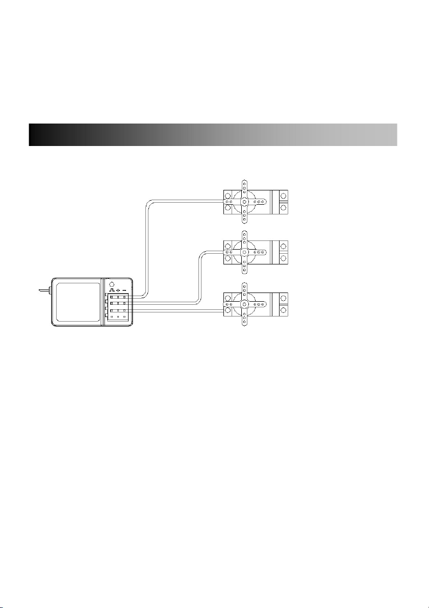
Receiver’s connection and installation:(such as some car model)
Rudder
Servo(CH1)
Throttle
Servo(CH2)
Servo(CH3)
NOTICE:
1. Confirm battery, switch, servos and etc are connected with receiver right.
2. While installing servos, please keep servo’s distance from model body,
otherwise the vibration can lead to servo and make servo damaged.
3. After installation of servos, please try to control the servo to full travel, if it
got stuck or sounded abnormal, you must solve the problem. Even if servo
was not damaged, large circuit occurred.
4. Do not cut off or bind the receiver antenna, and try the best to keep it far
away from metal and carbon graphite material.
5. Receiver is made up from precise electronic components, it need to be
protected from vibration by packaged with sponge or other shock
absorption materials.
Code-matching method between transmitter and receiver:
5
1. Load the battery into transmitter, power on it.
Display when power switch turned on
2. Connect the power to the 2nd Channel pin of receiver.
3. Press the binding button on the receiver till LED starts twinkling.
4. LED stops the twinkle, bright light indicates a successful
code-matching was completed.
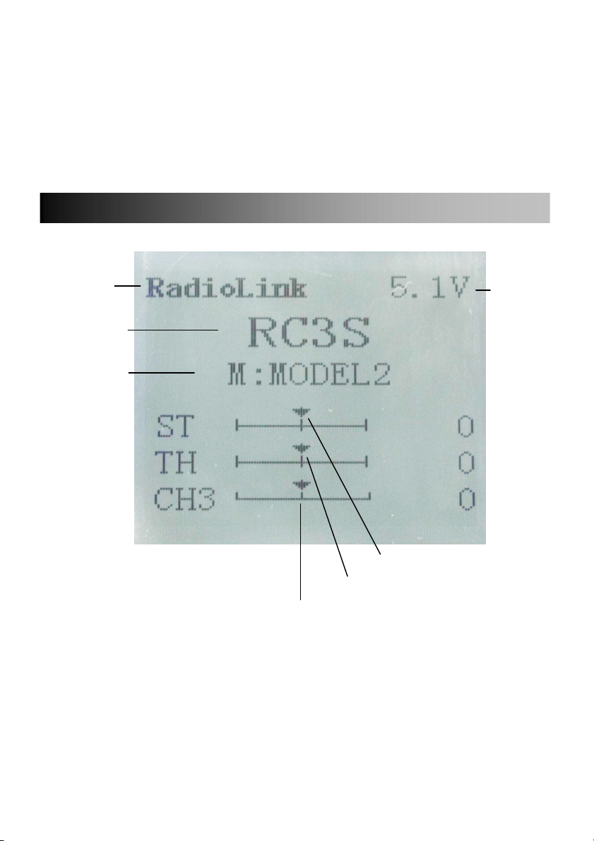
Co mp any Battery
Logo volta ge
display
R/C control
system name
Model name
Steering trim display
Throttle trim display
CH3 trim display
LCD Screen
When you power on the transmitter, LCD screen shows company name, the
battery voltage, R/C control system name, model name, steering trim, throttle trim,
CH3 trim.
Model Name
RC3S can store the data for 5 models, model name will show on the LCD when
6

you power on the transmitter. Please make sure the model name the screen displayed
Language
Select "
LANGUAGE
"
is the right what you want. If the model name you chose is not corresponding with
your model, the pre-settings should be wrong.
Transmitter battery voltage
In addition to the model#, LCD can show the voltage of battery. When the
voltage is lower than 4.6V, it would start the low-voltage alert, it would send out
“BeBe…” sounds, till the transmitter is power-off. When you hear the low-voltage
alert, you have no more than 4 minutes for controlling your model, please safely stop
your model before the uncontrolled situation. Please make sure the battery voltage is
higher than this voltage data while radio controlling.
Transmitter function menu setting
When you want to browse or change a setting of transmitter, you should go into
function menu setting mode. Under function menu setting mode, you can set up
Language Select "LANGUAGE",Model Select "MODEL", End Point Adjuster "EPA",
Steering EXP "STEXP", Steering Speed "STSPD", Throttle EXP "THEXP", Throttle
Speed "THSPD", A.B.S. Function "A.B.S", Throttle Acceleration "ACCEL", Idle-Up
"IDLUP", Subtrim "SUBTR", Servo Reverse "REV", Steering Dual Rate/Second
Dual Rate "D/R", ATL Function "ATL", Programmable Mixes "PMIX", Channel 3
Position "CH3",Model name "NAME", Reset function "RESET".
Notice: The functions of transmitter are ranged in the display in sequence, please read
all program setting orders before setting up your model data.
Both English and Chinese version menu are available for RC3S, which is convenient
for Chinese and English-speaking players to personalize function menus .
1. Access the function menu (By pressing “Exit” and “Enter” buttons simultaneously
and holding them down for one second ), the Language select function will be chosen.
7
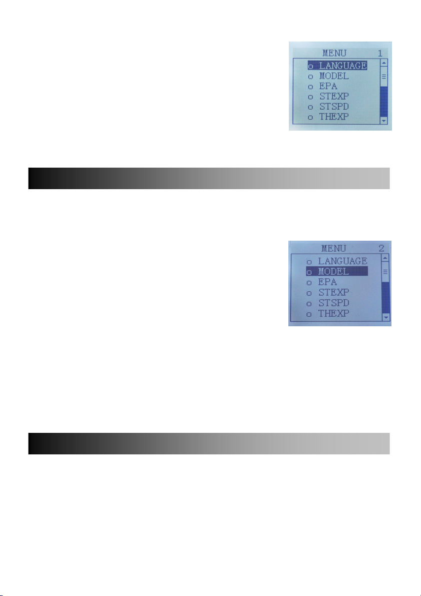
2. Press “Enter” button to get into “LANGUAGE”function
Model Select "M
OD
EL"
End Point Adjuster "EPA"
interface。
3. Use“Dec(-)”or “Inc(+)”key to select“中文”or
“English”,the selected language will be with black
shading effect.
4. Press “Enter” button, the desired language is
selected,and return to the initial screen automatically.
The RC3S transmitter can store model memories for five models. Use this function to
call a new model #.
MODEL- Model select function
1.Access the function menu (By pressing “Exit” and
“Enter” buttons simultaneously and holding them down for
one second ), press “Enter”key once, the Model select
function will be chosen.
2.Press “Enter” button, the current active model will be
blinking.
3.To activate a different model# by pressing “Dec(-)” or “Inc(+)” button until the
desired model# blinks.
4.Press “Enter” button, the selected model# stops blinking, now the model# has been
selected.
5. Return to the initial screen by pressing “Exit” button twice.
Use this when performing left and right steering angle adjustments, throttle high
side/brake side operation amount adjustment, and channel 3 servo up side/down side
opera-tion amount adjustment during linkage.
Correct the maximum steering angle and left and right steering angles when there is a
difference in the turning radius due to the characteristics, etc. of the vehicle.
8

Setting item (channel and direction)
Steering EXP "STEXP"
ST-LFT:Steering (left side)
ST-RGT:Steering (right side)
TH-FWD:Throttle (foward side)
TH-BRK:Throttle (brake side)
3C-UP:3rd channel (up side)
3C-DWN:3rd channel (down side)
Steering EPA Throttle EPA Steering EPA
ST-LFT:0~120 TH-FWD:0~120 3C-UP:0~120
ST-RGT:0~120 TH-BRK:0~120 3C-DWN:0~120
Initial value:120 Initial value : 120 Initial value :120
End point adjustment
1.Access the function menu (By pressing “Exit” and “Enter” buttons simultaneously
and holding them down for one second ),press “Inc(+)” button twice to chose EAP
function.
2.Press “Enter” button to get into EPA function interface, use “Dec(-)” or “Inc(+)”
button to select the desired setting item , press “Enter” key the initial value of your
selected setting item will blink, then you can press “Dec(-)” or “Inc(+)” button to
adjust the value of your selected setting item.
(Note: In the interface of adjusting the value, return to the initial value "120" by
pressing “Dec(-)” and “Inc(+)” buttons simultaneously for about 1 second.)
3. Press “Enter” button, the adjusted value of your selected setting item stops blinking,
now the value of your selected setting item has been set.
4. Return to the initial screen by pressing “Exit” button twice.
This function is used to change the sensitivity of the steering servo around the neutral
position. It has no effect on the maximum servo travel.
9

Setup item
Steering Speed "STSPD"
RATE: Steering EXP rate
Adjustment range
-100~0~+100
Initial value :0
Steering operation curve adjustment
1.Access the function menu (By pressing “Exit” and “Enter” buttons simultaneously
and holding them down for one second ), press “Inc(+)” button three times to chose
EAP function.
2.Press “Enter” button to get into STEXP function interface, press “Enter” key and
the initial value of the rate will blink, then you can press “Dec(-)” or “Inc(+)” button
to adjust the value and the curve of the rate shown in the figure will change
correspondingly.
(Note: In the interface of adjusting the value, return to the initial value "0" by pressing
“Dec(-)” and “Inc(+)” buttons simultaneously for about 1 second.)
3. Press “Enter” button, the adjusted value of the rate stops blinking, now the value
of the rate has been set.
4. Return to the initial screen by pressing “Exit” button twice.
Note: the Vertical cursor shown in the figure moves in step with steering wheel
operation.
Quick steering operation will cause momentary understeering, loss of speed, or
spinning. This function is effective in such cases.
10

Setup item
Throttle EXP "THEXP"
TURN:TURN direction
RETURN:RETURN direction
Adjustment range
1~100% (each direction)
At 100%, there is no delay
Steering servo delay
1.Access the function menu (By pressing “Exit” and “Enter” buttons simultaneously
and holding them down for one second ), press “Inc(+)” button four times to chose
STSPD function.
2.Press “Enter” button to get into STSPD function interface, press “Dec(-)” or
“Inc(+)” button to select setup item, then press “Enter” key and the initial value of
selected setup item will blink.
3.Use “Dec(-)” or “Inc(+)” button to adjust the value of the selected setup item.
(Note: In the interface of adjusting the value, return to the initial value "100" by
pressing “Dec(-)” and “Inc(+)” buttons simultaneously for about 1 second.)
4. Press “Enter” button, the adjusted value of the selected setup item stops blinking,
now the value of the selected setup item has been set.
5. Return to the initial screen by pressing “Exit” button twice.
This function makes the throttle high side and brake side direction servo operation
quicker or milder. It has no effect on the servo maximum operation amount.For the
high side, selection from among two kinds of curves (EXP/VTR/CRV) is also
possible.
Throttle curve adjustment
Adjustment method for EXP curve
11

Setup items
RATE:Forward side rate
FWD:Forward side curve selection
BRK:Brake side rate
Adjustment range
RATE:-100 ~ 0 ~ +100
FWD: EXP, VTR, CRV
BRK:-100 ~ 0 ~ +100
1.Enter the function menu and use “Dec(-)” or “Inc(+)” button to access THEXP
function.
2.Press “Enter” button to get into THEXP function interface, if initial FWD setup
item is EXP ,{ if initial FWD setup item is VTR or CRV, you need to select VTR or
CRV at setup item "FWD" by pressing “Dec(-)” or “Inc(+)” button, then press “Enter”
key, VTR or CRV will blink, press “Dec(-)” or “Inc(+)” button ,when the blinking
VTR or CRV change to blinking EXP, press “Enter” button, EXP will stop blinking,
now EXP is selected}, press “Dec(-)” or “Inc(+)” button to select RATE for forward
side adjustment or select BRK for brake side adjustment.
Forward side adjustment(select RATE)
(1).Press “Enter” key, the current RATE value will blink, Use “Inc(+)” button to
adjust the + side when you want to quicken the rise and use “Dec(-)” button to adjust
the - side when you want to make the rise milder.
(Note: In the interface of adjusting the value, return to the initial value "0" by pressing
“Dec(-)” and “Inc(+)” buttons simultaneously for about 1 second.)
(2).Press “Enter” button, the adjusted RATE value stops blinking, now the RATE
value has been set.
Brake side adjustment(select BRK)
(1).Press “Enter” key, the current BRK value will blink, use “Inc(+)” button to
adjust the + side when you want to quicker the rise and use “Dec(-)” button to adjust
12

the - side when you want to make the rise milder.
(Note: In the interface of adjusting the value, return to the initial value "0" by pressing
“Dec(-)” and “Inc(+)” buttons simultaneously for about 1 second.)
(2). Press “Enter” button, the adjusted BRK value stops blinking, now the BRK
value has been set.
3.When ending setting, return to the initial screen by pressing “Exit” button twice.
Adjustment method for VTR curve
Setup items
RATE:Forward side rate
TG.P:Curve switching point
FWD:Forward side curve selection
BRK:Brake side rate
Adjustment range
RATE:-100 ~ 0 ~ +100
TG.P:20 ~ 80%
FWD: EXP, VTR, CRV
BRK:-100 ~ 0 ~ +100
1.Enter the function menu and use “Dec(-)” or “Inc(+)” button to access THEXP
function.
2.Press “Enter” button to get into THEXP function interface, if initial FWD setup
item is VTR,{ if initial FWD setup item is EXP or CRV, firstly you need to select
EXP or CRV at setup item "FWD" by pressing “Dec(-)” or “Inc(+)” button, then press
“Enter” key, EXP or CRV will blink, press “Dec(-)” or “Inc(+)” button, when the
blinking EXP or CRV change to blinking VTR, press “Enter” button,VTR will stop
blinking ,now VTR is selected}, press “Dec(-)” or “Inc(+)” button to select RATE
for forward side adjustment or select TG.P for curve switching point adjustment or
select BRK for brake side adjustment.
13

Forward side adjustment(select RATE)
(1).Press “Enter” key, the current rate value will blink, Use “Inc(+)” button to adjust
the + side when you want to quicken the rise and use “Dec(-)” button to adjust the -
side when you want to make the rise milder.
(Note: In the interface of adjusting the value, return to the initial value "0" by pressing
“Dec(-)” and “Inc(+)” buttons simultaneously for about 1 second.)
(2). Press “Enter” button, the adjusted RATE value stops blinking, now the RATE
value has been set.
Curve switching point adjustment(select TG.P)
(1).Press “Enter” key, the current TG.P value will blink, use “Dec(-)” or “Inc(+)”
button to move to the point you want to set.
(Note: In the interface of adjusting the value, return to the initial value "50" by
pressing “Dec(-)” and “Inc(+)” buttons simultaneously for about 1 second.)
(2). Press “Enter” button, the adjusted TG.P value stops blinking, now the TG.P value
has been set.
Brake side adjustment(select BRK)
(1).Press “Enter” key, the current BRK value will blink, use “Inc(+)” button to
adjust the + side when you want to quicker the rise and use “Dec(-)” button to adjust
the - side when you want to make the rise milder.
(Note: In the interface of adjusting the value, return to the initial value "0" by pressing
“Dec(-)” and “Inc(+)” buttons simultaneously for about 1 second.)
(2). Press “Enter” button, the adjusted BRK value stops blinking , now the BRK
value has been set.
3.When ending setting, return to the initial screen by pressing “Exit” button twice.
Adjustment method for CRV curve
Setup items
1:~5:Curve points 1~5
FWD:Forward side curve selection
BRK:Brake side rate
14

Adjustment range
1: ~ 5: 0 ~ 100%
FWD: EXP, VTR, CRV
BRK: -100 ~ 0 ~ +100%
1.Enter the function menu and use “Dec(-)” or “Inc(+)” button to access THEXP
function.
2.Press “Enter” button to get into THEXP function interface, if initial FWD setup
item is CRV,{ if initial FWD setup item is EXP or VTR, firstly you need to select
EXP or VTR at setup item "FWD" by pressing “Dec(-)” or “Inc(+)” button, then press
“Enter” key, EXP or VTR will blink, press “Dec(-)” or “Inc(+)” button, when the
blinking EXP or VTR change to blinking CRV,press “Enter” button,CRV will stop
blinking, now CRV is selected}, press “Dec(-)” or “Inc(+)” button to select curve
points 1~5 for curve point adjustment or select BRK for brake side adjustment.
Curve point adjustment(select select curve points 1~5)
(1).Press “Enter” key, the current curve point value will blink, use “Dec(-)” or
“Inc(+)” button to move to the point you want to set.
(Note: In the interface of adjusting the value, return to the initial value (the initial
value of curve point 1-5 is 17,33,50,65,82 seperately ) by pressing “Dec(-)” and
“Inc(+)” buttons simultaneously for about 1 second.)
(2). Press “Enter” button, the adjusted curve point value stops blinking, now the curve
point value has been set.
Brake side adjustment(select BRK)
(1).Press “Enter” key, the current BRK value will blink, use “Inc(+)” button to
adjust the + side when you want to quicker the rise and use “Dec(-)” button to adjust
the - side when you want to make the rise milder.
(Note: In the interface of adjusting the value, return to the initial value "0" by pressing
“Dec(-)” and “Inc(+)” buttons simultaneously for about 1 second.)
(2). Press “Enter” button, the adjusted BRK value stops blinking , now the BRK
15

value has been set.
Throttle Speed "THSPD"
3.When ending setting, return to the initial screen by pressing “Exit” button twice.
Throttle servo delay
Sudden trottle trigger operation on a slippery road only causes the wheels to spin and
the ve-hicle cannot accelerate smoothly. Setting the throttle speed function reduces
wasteful battery consumption while at the same time permitting smooth, enjoyable
operation.
Operation
Throttle servo (amp) operation is delayed so that the drive wheels will not spin even if
the trottle trigger is operated more than necessary. This delay function is not
performed when the trottle trigger is returned and at brake operation.
OFF,Speed 1 or speed 2 can be selected.
OFF means shut down the throttle speed function
Adjustment method for SPEED 1
Setup items
MODE:Speed type selection
ALL:Speed adjustment
Adjustment range
1~100 (each direction)
At 100, there is no delay
1.Enter the function menu and use “Dec(-)” or “Inc(+)” button to access THSPD
function.
2.Press “Enter” button to get into THSPD function interface.
3.If initial MODE setup item is SPEED 1,{ if initial MODE setup item is SPEED 2 or
OFF, you need to select SPEED 1 by pressing “Dec(-)” or “Inc(+)” button to select
16

MODE setup item , then press “Enter” key, SPEED 2 or OFF will blink, press
“Dec(-)” or “Inc(+)” button,when the blinking SPEED 2 or OFF change to blinking
SPEED 1, press “Enter” key, SPEED 1 will stop blink,now SPEED 1 is selected},
press “Dec(-)” or “Inc(+)” button to select ALL setup item, then press “Enter” key,
the initial value will blink, use “Dec(-)” or “Inc(+)” button to adjust the delay of the
entire throttle forward side range.
(Note: In the interface of adjusting the value, return to the initial value "100" by
pressing “Dec(-)” and “Inc(+)” buttons simultaneously for about 1 second.)
Press “Enter” button, the adjusted value stops blinking, now the value has been set.
4.When ending setting, return to the initial screen by pressing “Exit” button twice.
Adjustment method for SPEED 2
Setup items
MODE:Speed type selection
LOW:Low side range speed adjustment
HIGH:High side range speed adjustment
TGP1:Low and medium speed switching point
Adjustment range
LOW:1~100
HIGH:1~100
At 100, there is no delay
TGP1:1~100
1.Enter the function menu and use “Dec(-)” or “Inc(+)” button to access THSPD
function.
2.Press “Enter” button to get into THSPD function interface.
3.If initial MODE setup item is SPEED 2,{ if initial MODE setup item is SPEED 1,
you need to select SPEED 2 by pressing “Dec(-)” or “Inc(+)” button to select MODE
setup item , then press “Enter” key, SPEED 1 or OFF will blink, press “Dec(-)” or
“Inc(+)” button,when the blinking SPEED 1 or OFF change to blinking SPEED
17

2,press “Enter” key,SPEED 2 will stop blinking, now SPEED 2 is selected}, press
A.B.S. Function "A.B.S"
“Dec(-)” or “Inc(+)” button to select "LOW" or "HIGH" delay adjustment or
“TGP1” Speed switching point adjustment.
4.Press “Enter” key to confirm "LOW" or "HIGH" or “TGP1” setup item, and the
value of your selected setup item will blink. Use “Dec(-)” or “Inc(+)” button to adjust
the value.
(Note: In the interface of adjusting the value, return to the initial value (the initial
value of LOW and HIGH is “100”, the initial value of TGP1 is “30”) by pressing
“Dec(-)” and “Inc(+)” buttons simultaneously for about 1 second.)
Press “Enter” button, the adjusted value stops blinking, now your selected value has
been set.
5.When ending setting, return to the initial screen by pressing “Exit” button twice.
Pulse brake
When the brakes are applied while cornering with a 4 Wheel Drive or other type of
vehicle, understeer may occur. The generation of understeer can be eliminated and
corners can be smoothly cleared by using this function.
Operation
- When the brakes are applied, the throttle servo will pulse intermittently. This will
have the same effect as pumping the brakes in a full size car.
- The brake return amount, pulse cycle, and brake duty can be adjusted.
- The region over which the ABS is effective can be set ac-cording to the steering
operation. (Mixing function)
Setup items
ABP: Brake return amount
DLY: Delay amount
CYC: Cycle speed
TGP: Operation point
DTY: Cycle duty ratio
18

STM: Steering mixing
- ABP : Amount of brake returnSets the rate at which the servo returns versus trigger
operation for brake release. When set to 0%, the ABS function is not performed.
When set to 50%, the servo returns 50% (1/2) of the trigger operation amount and
when set to 100%, the servo returns to the neutral position.
- DLY : DelaySets the delay from brake operation to ABS operation. When set to 0%,
the ABS function is activated without any delay. AT 50%, the ABS function is
activated after a delay of approximately 0.7 second and at 100%, the ABS function is
activated after a delay of approximately 1.4 seconds.
- CYC : Pulse speedSets the pulse speed (cycle). The smaller the set value, the faster
the pulse cycle.
- TGP : Trigger pointSets the trigger point at which the ABS function begins to
operate at brake operation.
- DTY : Cycle duty ratioSets the proportion of the time the brakes are applied and the
time the brakes are re-leased by pulse operation. The ratio can be set to +3 ~ 0 ~ -3 in
7 steps.
- STM : Steering mixingSets ABS operation ON/OFF according to the steering
operation range.
A.B.S function adjustment
Enter the function menu and use “Dec(-)” or “Inc(+)” button to access A.B.S
function, then press “Enter” button to get into A.B.S function interface.
1. (Brake return amount adjustment)
Select the setting item "ABP" by pressing “Dec(-)” or “Inc(+)” button, then press
“Enter” key and the initial value of “ABP” will blink. Use “Dec(-)” or “Inc(+)” button
to adjust the return amount.
(Note: In the interface of adjusting the value, return to the initial value "50" by
pressing “Dec(-)” and “Inc(+)” buttons simultaneously for about 1 second.)
Press “Enter” button, the adjusted value stops blinking, now the value has been set.
"0":No return
19

"50":Return to the 50% position of the brake operation amount
"100":Return to the neutral position.
Brake return amount (ABP)
0 ~ 50 ~ 100
Initial value; 50
- Brake return amount (ABP) is influenced by the "EXP" rate on the brake side.
2. (Delay amount setup)
Select the setting item "DLY" by pressing “Dec(-)” or “Inc(+)” button, then press
“Enter” key and the initial value of “DLY” will blink. Use “Dec(-)” or “Inc(+)” button
to adjust the delay amount.
(Note: In the interface of adjusting the value, return to the initial value "0" by pressing
“Dec(-)” and “Inc(+)” buttons simultaneously for about 1 second.)
Press “Enter” button, the adjusted value stops blinking, now the value has been set.
"0":A.B.S. function performed without any delay
"50":A.B.S function performed after an approximate 0.7 sec delay
"100":A.B.S. function performed after an approximate 1.7 secs delay
Delay amount (DLY)
0 ~ 100
Initial value; 0
3. (Pulse speed adjustment)
Select setting item "CYC" by pressing “Dec(-)” or “Inc(+)” button, then press “Enter”
key and the initial value of “CYC” will blink. Use “Dec(-)” or “Inc(+)” button to
adjust the pulse speed (cycle).
(Note: In the interface of adjusting the value, return to the initial value "5" by pressing
“Dec(-)” and “Inc(+)” buttons simultaneously for about 1 second.)
Press “Enter” button, the adjusted value stops blinking, now the value has been set.
20

- The smaller the set value, the faster the pulse speed.
Cycle speed (CYC)
0 ~ 30
Initial value; 5
4. (Operation point setup)
Select setting item "TGP" by pressing “Dec(-)” or “Inc(+)” button, then press “Enter”
key and the initial value of “TGP” will blink. Use “Dec(-)” or “Inc(+)” button to
adjust the operation point.
(Note: In the interface of adjusting the value, return to the initial value "30" by
pressing “Dec(-)” and “Inc(+)” buttons simultaneously for about 1 second.)
Press “Enter” button, the adjusted value stops blinking, now the value has been set.
- Sets the throttle trigger position at which the A.B.S. function is performed. The
number is the % display with the full brake position made 100.
Operation point (TGP)
0 ~ 100
Initial value; 30
5. (Cycle duty ratio setup)
Select setting item "DTY" by pressing “Dec(-)” or “Inc(+)” button, then press “Enter”
key and the initial value of “DTY” will blink. Use “Dec(-)” or “Inc(+)” button to
adjust the duty ratio.
(Note: In the interface of adjusting the value, return to the initial value "0" by pressing
“Dec(-)” and “Inc(+)” buttons simultaneously for about 1 second.)
Press “Enter” button, the adjusted value stops blinking, now the value has been set.
"-3":Brake application time becomes shortest. (Brakes lock with difficulty)
"+3":Brake application time becomes longest (Brakes lock easily)
(Remark) For low grip, set at the - side and for high grip, set at the + side.
21

Duty ratio (DTY)
Throttle A
cceleration "ACCEL"
-3 ~ 0 ~ +3
Initial value; 0
6. (Steering mixing setup)
Select setting item "STM" by pressing “Dec(-)” or “Inc(+)” button, then press “Enter”
key and the initial value of “STM” will blink. Use “Dec(-)” or “Inc(+)” button to
adjust the steering mixing range.
(Note: In the interface of adjusting the value, return to the initial value "OFF" by
pressing “Dec(-)” and “Inc(+)” buttons simultaneously for about 1 second.)
Press “Enter” button, the adjusted value stops blinking, now the value has been set.
- Sets the range within which the A.B.S. function is performed relative to steering
wheel operation.
Steering mixing (STM)
OFF, N10 ~ N100, E10 ~ E100
Initial value; OFF
When steering mixing is set and steering operation enters the set range, "*" is
displayed in front of the number. When mixing is OFF, the A.B.S function can operate
over the entire steering range.
7. When ending setting, return to the initial screen by pressing “Exit” button twice.
Function which adjusts the movement characteristic from the throttle
neutral position
The servo will jump to the input position at its maximum possible speed. Unlike
22

exponential, which adjusts the whole throttle movement into a curve, throttle
acceleration simply "jumps" away from neutral and then leaves the remaining
response linear.
Setup item
FWRD:Forward side acceleration amount
BRAK:Brake side acceleration amount
Throttle acceleration adjustment
Enter the function menu and use “Dec(-)” or “Inc(+)” button to access ACCEL
function, then press “Enter” button to get into ACCEL function interface.
1.(Forward acceleration amount adjustment)
Press “Dec(-)” or “Inc(+)” button to select “FWRD”, press “Enter” key to confirm
and the initial value of “FWRD” will blink, then use “Dec(-)” or “Inc(+)” button
adjust the acceleration amount.
(Note: In the interface of adjusting the value, return to the initial value "0" by pressing
“Dec(-)” and “Inc(+)” buttons simultaneously for about 1 second.)
Press “Enter” button, the adjusted value stops blinking, now the value has been set.
"0":No acceleration
"100":Maximum acceleration (Approximately 1/2 of the forward side steering angle)
Forward acceleration amount(FWRD)
0~100
Initial value: 0
2. (Brake side acceleration amount adjustment)
Press “Dec(-)” or “Inc(+)” button to select “BRAK”, press “Enter” key to confirm and
the initial value of “BRAK” will blink, then use “Dec(-)” or “Inc(+)” button adjust the
23

acceleration amount.
Idle-Up "IDLUP"
(Note: In the interface of adjusting the value, return to the initial value "0" by pressing
“Dec(-)” and “Inc(+)” buttons simultaneously for about 1 second.)
Press “Enter” button, the adjusted value stops blinking, now the value has been set.
"0":No acceleration
"100":Maximum acceleration (Brake side maximum steering angle)
Brake side acceleration amount(BRAK)
0~100
Initial value: 0
3. When ending setting, return to the initial screen by pressing “Exit” button twice.
Idle up at engine start
Use this function to improve the starting characteristics of the engine by raising the
idling speed when starting the engine of a gas powered car.
Idle-Up rate (RATE)
D50% ~ D1%, 0%, U1% ~ U50%
Initial value: 0%
"D": Brake side
"U": Forward side
1.Enter the function menu and use “Dec(-)” or “Inc(+)” button to access IDLUP
function.
2.Press “Enter” button to get into IDLUP function interface.
3.Press “Enter” key, and the initial value of RATE will blink. Use “Dec(-)” or
“Inc(+)” button to adjust the value.
24

(Note: In the interface of adjusting the value, return to the initial value "0%" by
Subtrim "SUBTR"
pressing “Dec(-)” and “Inc(+)” buttons simultaneously for about 1 second.)
Press “Enter”button, the adjusted value stops blinking, now the value has been set.
4.When ending setting, return to the initial screen by pressing “Exit” button twice.
Servo center position fine adjustment
Use this function to adjust the neutral position of the steering, throttle and channel 3
servos.
Channel
ST:Steering
TH:Throttle
CH3:Channel3
Subtrim
ST:L100~R100
TH:B100~F100
CH3:-100~+100
Initial value : 0
1.Enter the function menu and use “Dec(-)” or “Inc(+)” button to access SUBTR
function.
2.Press “Enter” button to get into SUBTR function interface.
3. Use “Dec(-)” or “Inc(+)” button to select ST channel, press “Enter” key, and the
initial value of ST will blink. Use “Dec(-)” or “Inc(+)” button to adjust the center.
(Note: In the interface of adjusting the value, return to the initial value "0" by pressing
“Dec(-)” and “Inc(+)” buttons simultaneously for about 1 second.)
4.Press “Enter” key, the adjusted value stops blinking, now the center of ST has
been adjusted.
5. TH channel and CH3 channel can be set similarly.
25

6.When ending setting, return to the initial screen by pressing “Exit” button twice.
Servo Reverse "REV"
Steerin
g
Dual Rate/
Throttle
Dual Rate "D/R"
Servo operation reversing
This function reverses the direction of operation of the servos related to
transmitter steering, throttle, and channel 3 operation.
Channel
ST:Steering
TH:Throttle
CH3:Channel3
1.Enter the function menu and use “Dec(-)” or “Inc(+)” button to access REV
function.
2.Press “Enter” button to get into REV function interface.
3. Use “Dec(-)” or “Inc(+)” button to select ST channel, press “Enter” key, and the
symbol “NOR REV” will blink. Use “Dec(-)” or “Inc(+)” button to reverse the ST
servo operation direction.
4.Press “Enter” key, the symbol “NOR REV” stops blinking, now the ST servo
operation direction has been set.
5. TH channel and CH3 channel can be set similarly.
6.When ending setting, return to the initial screen by pressing “Exit” button twice.
Dual rate
The steering left and right servo travels are adjusted simultaneously. When you want
to increase the servo travel, adjust the + side. When you want to decrease the servo
travel, adjust the – side.
26

Setup Item
ATL Function "ATL"
Steering D/R
RATE
Throttle D/R
RATE
Steering D/R rate (RATE)
0~100%
Initial value: 100
Throttle D/R rate (Throttle D/R RATE)
0~100%
Initial value: 100
1.Enter the function menu and use “Dec(-)” or “Inc(+)” button to access D/R
function.
2.Press “Enter” button to get into D/R function interface.
3. Use “Dec(-)” or “Inc(+)” button to select Steering D/R RATE, press “Enter” key,
and the initial value of Steering D/R RATE will blink. Use “Dec(-)” or “Inc(+)”
button to make adjustments.
(Note: In the interface of adjusting the value, return to the initial value "100" by
pressing “Dec(-)” and “Inc(+)” buttons simultaneously for about 1 second.)
4.Press “Enter” key, the adjusted value stops blinking, now the steering D/R RATE
has been set.
5. Throttle D/R RATE can be set similarly.
6.When ending setting, return to the initial screen by pressing “Exit” button twice.
Brake side adjustment
This function decreases the set value when the braking effect is strong and
increases the set value when the braking effect is weak.
27

Setup Item
Programmable Mixes "PMIX
"
RATE:Brake amount
Brake amount (RATE)
0~100%
Initial value: 100%
1.Enter the function menu and use “Dec(-)” or “Inc(+)”
button to access ATL function.
2.Press “Enter” button to get into ATL function interface.
3.Press “Enter” key, and the initial value of RATE will blink. Use “Dec(-)” or
“Inc(+)” button to adjust the value.
(Note: In the interface of adjusting the value, return to the initial value "100%" by
pressing “Dec(-)” and “Inc(+)” buttons simultaneously for about 1 second.)
Press “Enter” button, the adjusted value stops blinking , now the value has been set.
4.When ending setting, return to the initial screen by pressing“Exit” button twice.
Programmable mixes between arbitrary channels
These functions allow you to apply mixing between the steering, throttle, and channel
3 channels.
Setup items
LEFT:Mixing rate (Left side)
RGHT:Mixing rate (Right side)
MST:Master channel
SLV:Slave channel
MXMD:Mix mode
Enter the function menu and use “Dec(-)” or “Inc(+)” button to access PMIX
function, then press “Enter” button to get into PMIX function interface.
28

1.(Master channel)
Channel selection (MST)
ST, TH, CH3
Initial value: ST
Select setup item "MST" by pressing “Dec(-)” or “Inc(+)” button, press “Enter”
button, the initial master channel will blink. Use “Dec(-)” or “Inc(+)” button to select
the master channel you wish to adjust, press “Enter”button, the blinking master
channel you selected will stop blinking.
2.(Slave channel)
Channel selection (SLV)
ST, TH, CH3
Initial value:ST
Select setup item "SLV" by pressing “Dec(-)” or “Inc(+)” button, press “Enter” button,
the initial slave channel will blink. Use “Dec(-)” or “Inc(+)” button to select the slave
channel you wish to adjust, press “Enter” button, the blinking slave channel you
selected will stop blinking.
3. (Left, forward or up side mixing amount adjustment)
Mixing amount
-100~0~+100
Select the setting item "LEFT", "FWRD", or "UP"( These setup items are different
depend on the master channel. ST: "LEFT"; TH: "FWRD"; CH3: "UP" ) by pressing
“Dec(-)” or “Inc(+)” button . press “Enter” key, the initial value of "LEFT", "FWRD",
or "UP" will blink, Use “Dec(-)” or “Inc(+)” button to adjust the left, forward, or up
side mixing amount.
(Note: In the interface of adjusting the value, return to the initial value "0" by pressing
“Dec(-)” and “Inc(+)” buttons simultaneously for about 1 second.)
Press “Enter” key, the adjusted value stops blinking, the selected mixing amount has
been adjusted.
4.(Right, brake or down side mixing amount adjustment)
29

Mixing amount
Channel 3 Position "CH3"
-100~0~+100
Select the setting item "RGHT", "BRAK", or "DOWN" ( These setup items are
different depend on the master channel. ST: "RGHT"; TH: "BRAK"; CH3: "DOWN" )
by pressing “Dec(-)” or “Inc(+)” button . Press “Enter” key, the initial value of
"RGHT", "BRAK", or "DOWN" will blink, Use “Dec(-)” or “Inc(+)” button to adjust
the right, brake, or down side mixing amount.
(Note: In the interface of adjusting the value, return to the initial value "0" by pressing
“Dec(-)” and “Inc(+)” buttons simultaneously for about 1 second.)
Press “Enter” key, the adjusted value stops blinking, the selected mixing amount has
been adjusted.
5. (Mixing mode setup)
Mixing mode (MXMD)
OFF, MIX
Initial value: OFF
Select setup item "MXMD" by pressing “Dec(-)” or “Inc(+)” button, press “Enter”
button, the initial mixing mode “OFF” will blink. Press “Dec(-)” or “Inc(+)” button to
switch “OFF” to “MIX” , press “Enter” button, the blinking “MIX” will stop
blinking.
"OFF":Mixing proportional to master channel operation.
"MIX":Mixing by master channel another function considered.
6. When ending setting, return to the initial screen by pressing “Exit” button twice.
The channel 3 servo position can be set from the transmitter. When CH3 is assigned
to the 3
the 3
rd
channel key, this setting is linked to the key. When CH3 is not assigned to
rd
channel key, it can be set with this screen.
30

Setup Item
POSI: Channel 3 position
MODE: the 3
rd
channel “CH3 SWITCH” or “MENU SET”
CH3:Channel 3 subtrim
Channel 3 position (POSI)
-100~+100
Initial value: 0
1.Enter the function menu and use “Dec(-)” or “Inc(+)” button to access CH3
function.
2.Press “Enter” button to get into CH3 function interface.
3.Use “Dec(-)” or “Inc(+)” button to select MODE setup item.
If the initial MODE setup item is “CH3 SWITCH” .
Use “Dec(-)” or “Inc(+)” button to select POSI, press “Enter” key and the initial value
of POSI will blink, use “Dec(-)” or “Inc(+)” button to adjust the value and this value
can only be adjusted to +100 or -100.
Press “Enter” button, the adjusted value stops blinking, now the value has been set.
If the initial MODE setup item is “MENU SET”.
Use “Dec(-)” or “Inc(+)” button to select POSI, press “Enter” key and the initial value
of POSI will blink, use “Dec(-)” or “Inc(+)” button to adjust the value and this value
can be adjusted between +100 and -100 .
(Note: In the interface of adjusting the value, return to the initial value "0" by pressing
“Dec(-)” and “Inc(+)” buttons simultaneously for about 1 second.)
Press “Enter” button, the adjusted value stops blinking, now the value has been set.
Note : When the initial MODE setup item is “MENU SET”, the CH3 setup item is
effective and can be adjusted by using AUX switch, and the range is -100~+100.
When the initial MODE setup item is “CH3 SWITCH”, the CH3 setup item is
ineffective.
4.When ending setting, return to the initial screen by pressing “Exit” button twice.
31

Reset
function
"RESET"
Model name
"
NAME
"
RC3S stores model memories for five models.Each model memory can be named
separately according to user’s requirement.
Factory default name: MODEL5
1.Enter the function menu and use “Dec(-)” or “Inc(+)”
button to access NAME function.
2.Press “Enter” button to get into NAME function
interface,the first character of current name will blink, and
the blinking character can be reset. The common use
characters appear at the bottom of the screen, use
“Dec(-)” or “Inc(+)” button to choose the character you desired. Press “Enter” button
again, the next character of current name will blink. Reset other characters of current
name in same manner.
3.After accomplishment of naming, all characters of current name will stop blinking,
the new name will be stored automatically.
4.When ending setting, return to the initial screen by pressing“Exit” button twice.(the
new setting model name will appear on the initial screen)
REST- Data reset function:
All the data for any model memory can be reset to original factory defaults. Often this
function is done to get a “fresh start” and clear the memory before inputting new
model settings.
1.Enter the function menu and use “Dec(-)” or “Inc(+)”
button to access RESET function.
2.Press “Enter” button to get into RESET function
interface, the symbol “YES” will blink.
32

Be sure to reset
Press “Enter” key, the symbol “YES” will stop blinking, and return to the initial
screen. Now the model data is reset to the initial setting that is the default value set at
the factory.
Not to reset
Press “Dec(-)” or “Inc(+)” button, the symbol “YES” will stop blinking and the
symbol “NO” will blink, press “Enter” key, the symbol “NO” will stop blinking,
return to the initial screen by pressing “Exit” button twice.
Or you can press “Exit” button twice to quit resetting directly.
CAUTION: Resetting the current model memory will permanently erase ALL
programming information for that model. The data cannot be recovered .Do not reset
the model unless you are certain you want to clear-out that memory and start from
scratch.
Thank you again for using our product, we hope it can bring you happiness!
Warning:
This device complies with part 15 of the FCC Rules. Operation is subject
to the following two conditions:
(1) This device may not cause harmful interference, and
(2) this device must accept any interference received, including
interference that may cause undesired operation.
Any Changes or modifications not expressly approved by the party
responsible for compliance could void the user's authority to operate
the equipment.
33
 Loading...