

Page 1

Radiolink Electronic Ltd
www.radiolink.com
T8S
(FHSS)
8-Channel Remote Controller
Compatible with Fixed-wings/Gliders/Multirotors/Cars/Boats
Instruction Manual
CE FCC RoHS
* Please be kindly noted that this manual will be updated regularly and please visit RadioLink
official website to download the latest version.
Page 2
Radiolink Electronic Ltd
www.radiolink.com
Thank you for purchasing RadioLink 8-channel remote controller T8S.
To fully enjoy the benefits of this product and ensure safety, please read the manual carefully and set up
the device as instructed steps.
If any problems found during the operation process, either way listed below can be used as online tech
support.
1. Send mails to after_service@radiolink.com.cn or after_service1@radiolink.com.cn and we will answer your
question at the earliest.
2. PM us on our Facebook page or leave comments on our Youtube page
3. If the product is purchased from the local distributor, you can also ask them for support and repair as prefer.
All manuals and firmwares are available on RadioLink official website www.radiolink.com and more tutorials are
uploaded. Or follow our Facebook and Youtube homepage to stay tuned with our latest news.
SAFETY PRECAUTIONS
Never operate models during adverse weather conditions. Poor visibility can cause disorientation and loss
of control of pilots’model.
Never use this product in a crowd or illegal areas.
Always check all servos and their connections prior to each run.
Always be sure about turning off the receiver before the transmitter.
To ensure the best radio communication, please enjoy the flight/driving at the space without interference
such as high voltage cable, communication base station or launching tower.
WARNING
This product is not a toy and is NOT suitable for children under the age of 18. Adults should keep the product
out of the reach of children and exercise caution when operating this product in the presence of children.
Water or moisture may enter the transmitter inside through gaps in the antenna or joystick and cause model
instability, even out of control. If running in the wet weather(such as game) is inevitable, always use plastic
bags or waterproof cloth to cover the transmitter.
FCC Statement
This equipment has been tested and found to comply with the limits for a Class B digital device, pursuant to
Part 15 of the FCC Rules. These limits are designed to provide reasonable protection against harmful
interference in a residential installation. This equipment generates uses and can radiate radio frequency
Page 3

Radiolink Electronic Ltd
No.
Items
Qty
Unit1TX T8S
1
Piece
2
RX R8EF
1
Piece
3
OTG Cable
1
Piece
4
Throttle-Stick
Spring
Retainer
1
Piece
www.radiolink.com
energy and, if not installed and used in accordance with the instructions, may cause harmful interference to
radio communications. However, there is no guarantee that interference will not occur in a particular installation.
If this equipment does cause harmful interference to radio or television reception, which can be determined by
turning the equipment off and on, the user is encouraged to try to correct the interference by one or more of the
following measures:
-- Reorient or relocate the receiving antenna.
-- Increase the separation between the equipment and receiver.
-- Connect the equipment into an outlet on a circuit different from that to which the receiver is connected.
-- Consult the dealer or an experienced radio/TV technician for help.
This device complies with part 15 of the FCC Rules. Operation is subject to the following two conditions:
(1) This device may not cause harmful interference, and (2) this device must accept any interference received,
including interference that may cause undesired operation.
Changes or modifications not expressly approved by the party responsible for compliance could void the user's
authority to operate the equipment.
Packing List
Page 4

Content
Radiolink Electronic Ltd
www.radiolink.com
Chapter 1 Introduction
1.1 Installation of Remote Control.....................................................................................................................................1
1.1.1 Installation Receiver Antenna..........................................................................................................................1
1.1.2 Transmitter Battery Charging
1.2 T8S Basic Setup............................................................................................................................................................2
1.2.1 Compatible Receivers...................................................................................................................................... 2
1.2.2 Binding
1.2.3 Signal Switch between SBUS&PPM and PWM ......................................................................................... 3
1.2.4 T8S Gimbals Calibration.................................................................................................................................. 3
Chapter 2 Firmware Upgrade
Chapter 3 Parameters Setup via Mobile.......................................................................................................................... 6
3.1 Android APP Installation............................................................................................................................................6
3.2 Connection
3.3 Parameters Setup Menu........................................................................................................................................... 7
3.3.1 SERVO Menu.....................................................................................................................................................8
3.3.2 BASIC Menu
3.3.3 ADVANCED Menu...........................................................................................................................................10
3.3.4 SYSTEM Menu................................................................................................................................................ 11
Chapter 4 T8S Parameters Setup via Computer
4.1 Software Installation and Connection...................................................................................................................... 12
4.2 Parameters Setup Menu............................................................................................................................................ 13
4.2.1 BASIC Menu
4.2.2 ADVANCE Menu..............................................................................................................................................14
Chapter 5 FAQ .............................................................................................................................................................. 15
......................................................................................................................................................
..........................................................................................................................
................................................................................................................................................................
............................................................................................................................................
..................................................................................................................................................................
......................................................................................................................................................
.......................................................................................................
....................................................................................................................................................
12
13
1
1
3
4
7
9
Page 5
Radiolink Electronic Ltd
CH7
CH5
CH6
CH8
www.radiolink.com
Chapter 1 Introduction
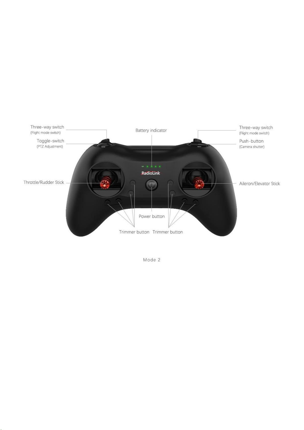
As image of T8S (Mode 2) shown below, there are two 3-way switches, one toggle-switch, one
push-button, eight trimmer buttons and two joysticks. The Mode can be personalized to 1(throttle on right hand)
or 2 (throttle on left hand) or both sticks return to center points with the small accessory packed in the bag.
Factory setting by default: CH5/3-way switch on the right, CH6/ Push-button, CH7/3-way switch on the
left, CH8/toggle-switch.
1.1 Installation of Remote Control
1.1.1 Installation of Receiver Antenna
1. Keep antennas as straight as possible, or the effective control range will reduce.
2. Big models may contain metal parts that influence signal emission. In this case. antennas should be
positioned at both sides of the model to ensure the best signal status in all circumstances.
3. Antennas should be kept away from metal conductor and carbon fiber at least half inch away and no over
bending.
4. Keep antennas away from motor, ESC or other possible interference sources.
5. Sponge or foam material is advised to use to prevent vibration when installing receiver.
6. Receiver contains some electronic components of high-precision. Be careful to avoid strong vibration and
high temperature.
7. Special vibration-proof material for R/C like foam or rubber cloth is used to pack to protect receiver. Keeping
1
Page 6
Radiolink Electronic Ltd
1) Channel Qty: 8
2) Operating Voltage:4.8-10V
3) Operating Current:30mA (Input Voltage 5V)
4) Dimension : 48.5*21*11mm
5) Weight:7g
CH8 (AUX)
CH7 (AUX)
CH6 (AUX)
CH5 (AUX)
CH4 (RUDD)
CH3 (THRO)
CH2 (ELEV)
CH1 (AILE)
Antenna
Binding Button (ID SET)
LED
www.radiolink.com
the receiver in a well sealed plastic bag can avoid humidity and dust, which would possibly make the receiver
out of control.
When all the above steps are complete, please turn off the transmitter and repower on to test if the receiver is
correctly connected with it.
1.1.2 T8S Battery Charging
The built-in battery of T8S is 1S lithium. When the voltage becomes low, the green indicator will flash with a DD
warning tone. Make sure to charge the battery in time to avoid the possible damage by over discharge.
T8S charging is as simple as only an android USB cable needed, connecting to the computer or portable
charger.
1.2 Basic Setup
1.2.1 Compatible Receivers
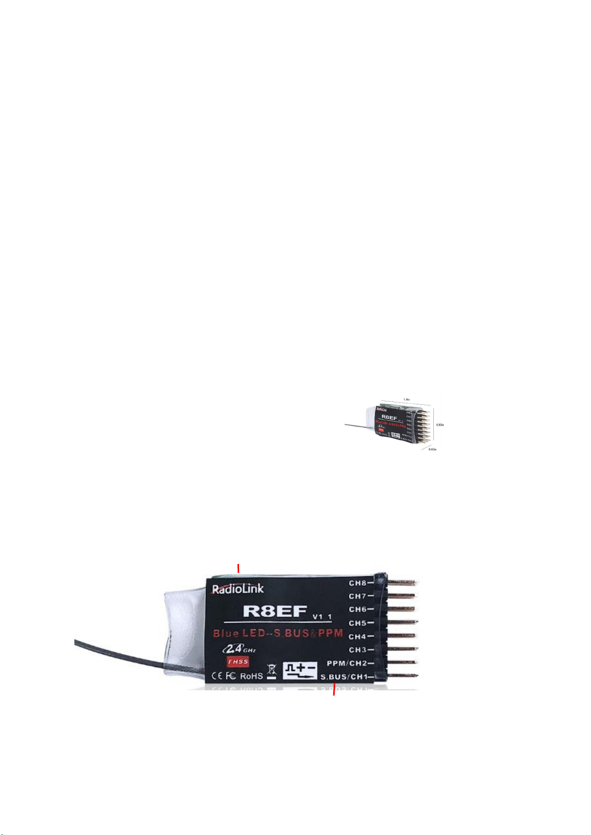
The standard receiver equipped to T8S is R8EF, 2.4G 8-channel receiver with SBUS,PPM and PWM signal
output supported. R8FM is another compatible receiver with extreme light weight of 2.5g and double signal
output of SBUS and PPM. The control distance of both receiver is up to 2000 meters.
R8EF Specifications
6) 2048 section precision, 0.5us per section, servo anti-shake rudder.
7) Distance: 2000m in the air (depending on the actual flight circumstances)
Signal Working Mode
(1) PWM Working Mode: Receiver indicator is RED with all 8 channels output PWM signal.
2
Page 7

Radiolink Electronic Ltd
Antenna
Binding Button(ID SET)
CH8 (AUX), PWM
CH7 (AUX),PWM
CH6 (AUX),PWM
CH5 (AUX),PWM
CH4 (RUDD),PWM
CH3 (THRO),PWM
PPM
SBUS
LED
Antenna
www.radiolink.com
(2) SBUS/PPM Working Mode
Receiver indicator is Blue(Purple) with 8 channels output in total. Channel 1 is SBUS signal, channel 2 PPM
signal and channel 3 to 8 PWM signal.
1.2.2 Binding
Every transmitter owns a unique ID code. Before using, binding transmitter to receiver on aircraft is a must.
When done binding, ID code will be stored in the receiver, no need to rebind, unless the receiver is going to
work with another transmitter. If a new R8EF or R8FM receiver is purchased, binding needs to be done before
using.
Binding steps of all transmitters and receivers from RadioLink are the same as follow:
(1) Put the transmitter and the receiver close to each other within 50 centimeters
(2) Power on the transmitter and the receiver. The receiver will bind to the closest transmitter.
(3) Press the ID SET on the side of the receiver for more than 1s, the flashing LED means binding starts.
When LED is always on (stops flashing), binding is complete.
(4)Check if servos move as the transmitter commands to verify the binding success.
1.2.3 Signal Switch between SBUS&PPM and PWM
R8EF: Short press the ID SET on the receiver twice within 1s to switch the SBUS/PPM signal to PWM signal.
When the RED LED is on, signal output is PWM. When both RED and BLUE LEDs are on. Signal output is
SBUS&PPM.
R8FM: Short press the ID SET on the receiver twice within 1s to switch the SBUS to PPM signal. When the
RED LED is on, PPM signal is output while SBUS signal is output when both RED and BLUE LEDs are on.
1.2.4 T8S Gimbals Calibration
When the transmitter is power-off, toggle both sticks at the central point. Then press the throttle trimmer button
(with an arrow to left and marked as No.1 in below pic ) and the power button simultaneously, the four green
indicators will start flashing and the T8S is ready to be calibrated..
3
Page 8

Radiolink Electronic Ltd
Throttle Trimmer Buttons
Elevator Trimmer Buttons
Aileron Trimmer Buttons
Rudder Trimmer Buttons
1
3
4
6
5
7
8
www.radiolink.com
Range Calibration: Toggle both sticks (Ch1-4) to the highest point/maximum and the lowest point/minimum.
Then back to the central point. (Refer to image below)
Central Point Calibration: When the joysticks are back to the central point, press the throttle trimmer button
(with an arrow to right and marked as No.2 in below pic). Two short DD sounds will be heard while the first
green indicator is always on, meaning the stick calibration is complete.
Chapter 2 Firmware Upgrade
T8S can be upgraded with latest functions added, keeping advanced as always.
The function of data backup makes massive copy possible, even the same model can directly copy data. Set
parameters once, copy at ease!
The whole file with all necessary tools can be download via
http://radiolink.com.cn/doce/Firmwares/T8S/T8Sparamsetuptools.rar
Note The latest firmware for T8S is under development and will be available very soon. The current
available one is T8S_FHSS_V803_69da_20190725_33bit.hex. as factory default. Below upgrade steps
are explained with the default firmware and this T8S manual and the zip file will upgrade as soon as the
latest T8S firmware comes out.
4
Page 9

1. Driver Installation: Select the correct driver depending on the computer system.
2. Connect T8S with computer via a USB cable
3. Open the software to upgrade T8S firmware
Radiolink Electronic Ltd
www.radiolink.com
3. Choose the correct COM port
4. Click CONNECT and press the power button once quickly within 1s. When “DISCONNECT” in red turns to
“CONNECT” in green, it means it’s connected with success.
5. Click“APROM” and choose the latest firmware, which will be constantly upgrading, please visit RadioLink
website to download the latest version
)
5
Page 10

Radiolink Electronic Ltd
www.radiolink.com
6. Click “START” and the process bar becomes green. When the green bar goes to the end and shows PASS,
the firmware is upgraded with success.
7. When upgrade with success, close the software and T8S will make three DEE sounds.
Chapter 3 Parameters Setup via Mobile
3.1 Android APP Installation
Scan the QR code on the right or choose the file RadiolinkT8FB/T8S.APK in the
zip file downloaded via http://radiolink.com.cn/doce/Firmwares/T8S/T8Sparamsetuptools.rar
and install into an Android phone.
Note The version of T8S parameters setup APP is only available on
Android mobiles with V4.0 or above. Some Android phones (eg. OPPO R9s) need to activate the OTG function
to ensure successful connection (Activate Steps: Settings - Other settings - OTG Connection)
6
Page 11

Radiolink Electronic Ltd
OTG
Cable
Android USB Cable
OTG cable must
connect with the
mobile
www.radiolink.com
3.2 Connection
When the installation of parameter setup app is complete, connect T8S with a Android phone as below picture
shown with a USB cable and a OTG cable. The APP interface will pop out, click ALLOW/CONFIRM to enter the
APP .
Note:The smaller head of the USB cable connects with T8S while the bigger head connects with OTG cable.
The smaller head of the OTG cable connects the mobile.
When the APP is installed and cables between T8S and android phone are connected correctly, a notice
will pop out to ask if ok to open the app. Click yes then the APP interface will pop out and displayed as
below. Then power on T8S.
3.3 Parameters Setup Menu
There are four parameter setup menus: SERVO/BASIC/ADVANCED/SYSTEM
Click CONNECT on top left of the interface, notice of “Device has attached to Android” will pop out and the
SERVO menu will be reached directly if connected with success. If fail, please click CONNECT again.
7
Page 12

Radiolink Electronic Ltd
www.radiolink.com
(DIS)CONNECT: When APP is opened on the mobile, T8S will be connected automatically. If can’t be identified,
click DISCONNECT then CONNECT again.
READ: Click READ, the APP will start reading the data in T8S, the process won’t complete until 4 D sounds are
heard. Every time reopen the APP, the data displayed are default. If any parameter is changed, it can’t be
displayed until clicking READ.
UPDATE: Click to update the changed data into the T8S and a D sound means update complete. If no D sound
means update failure. Click UPDATE each time parameter is modified.
SAVE: Click to save the APP data in the /model/model01.text in the mobile and APP will automatically create a
model01. txt file.
LOAD: Click LOAD and the APP will take the data from /model/model01.txt. APP will notify if this file can’t be
found.
CLOSE: Click Close to exit.
Note There is T8S(T8FB) voltage displaying on each menu.
Parameters Setting Steps
When parameters need to be modified, click READ first to input the original data into the software, then
modify as wish and click UPDATE to output the modified data to T8S.
When parameters SAVE as TXT file need to be input, click LOAD first to input the saved data into the
software then click UPDATE to copy them to T8S.
3.3.1 SERVO Menu
The 8 rectangles shows the CH1-CH8 servos range(4 basic channels and 4 auxiliary channel) from left to right.
8
Page 13

Radiolink Electronic Ltd
www.radiolink.com
3.3.2 BASIC Menu
There are six parameters to setup including ”REV”“SUB”“EPA-L”“EPA-R”“F/S”“DELAY”
REV: Defines the relationship between the transmitter controls and the receiver output for channels with
options of NORM and REV. Make sure to check all servos move to the correct direction as wish under control.
Make sure to check all servos move to the correct direction under control.
Note
If programmable mix control function is used to control several servos for fixed wing/gliders,
eg. V-TAIL mix control, make sure to set the phase to avoid possible confusion.
SUB: Makes small changes or corrections to the neutral position of each servo. The default is 0 setting by
factory setting. That is, no SUB-TRIM. The range is from -120 to +120 and can be modified with actual need.
It’s advised to center the digital trims before making SUB-TRIM changes, and keep all of the SUB-TRIM
values as small as possible. In order to restrict the servo travel range, the recommended procedure is as
follows:
•
Measure and record the desired surface position;
•
Zero out the SUB-TRIM ;
•
Mount servo arms and linkages so that the control surface’s neutral is as correct as possible;
•
Modify with SUB-TRIM small range value to make fine corrections.
EPA-L &EPA-R : Sets the range of each channel in percentage. The most flexible version of travel
adjustment is available. It independently adjusts each end of each individual servo’s travel, rather than one
setting for the servo affecting both directions. The default value is 96.
F/S: Sets responsive action of model in case of signal loss or low Rx voltage(in percentage).
Each channel can be set independently.
•
The NOR (normal) setting holds the servo in its last commanded position.
•
The F/S (Fail Safe) function moves each servo to a predetermined position.
Note
The setting of the throttle F/S also applies to the low battery voltage. F/S value 0 means throttle stick at the
lowest point while 50 means at the central point.
9
Page 14

Radiolink Electronic Ltd
www.radiolink.com
The F/S function is used in certain competitions to ensure safety landing of the model prior to flying away and
dropping. Conversely, it can also be used make all servos neutral to maximize the flight time.
DELAY: Adjusts the synchronous ratio between the servos position and the actual operation. The default
value is 100 by factory setting meaning no delay.
3.3.3 ADVANCED Menu
There are four parameters to setup: ”D/R” “ATTITUDE” “ELEVON” “V-TAIL”
D/R: Sets the auxilary switch to control the max and min values of corresponding channel range. Turn on “MIX”
(mix control) first and choose an auxilary switch to flip and set the max/min range value to its correspoding
channel by toggling. In the example picture shown above: When flip SWA upward and toggle CH1 stick , it
means the max/min range of CH1 can be +100 and -100. If the UP value modified to 50, it means the max
range can only be +50/-50 when toggle CH1 up and down. ‘DOWN” means when flip SWA downward, the
max/min value of CH1 is +100/-100.
ATTITUDE: Turn on “CH”first and select the preferred channel. The values behind each channel means
different control percentage output different control signals.
Pilots can set 6 different modes (NORMAL, ATTI, GPS, HOVER, F/S and AUX) by adjusting the related rates.
Every mode has different rates to get a unique signal. NORMAL mode preset 0%, ATTI 50%, GPS 100%,
HOVER 25%, F/S 75% and AUX 50%. 0% means a output signal 1ms, and 100% means 2ms.
Note If flight controller used is RadioLink PIX or Mini Pix, no setup needed here by default.
ELEVON: Turn on “MIX” (mix control) first, adjust the aileron distance and allow aileron differential.
ADJUSTABILITY:
•
CH1 and CH2 are required.
•
Independently adjustable aileron travel allows aileron differential.
•
Independently adjustable elevator travel allows for differences in up vs. down travel.
•
The separate ELEVON settings for each condition can be set. (GLIDER only)
10
Page 15

Radiolink Electronic Ltd
www.radiolink.com
V-TAIL: This function is used on the V-tail aircraft.
V-TAIL mixing is used with v-tail aircraft so that both elevator and rudder functions are combined for the two
tail surfaces. Both elevator and rudder travel can be adjusted independently on each surface.
ADJUSTABILITY:
• CH2 and CH4 are required.
• Independently adjustable travel allows for differences in servo travels.
• Rudder differential is not available. To create rudder differential, set RUD1 and 2 to 0, then use two
programmable mixes, RUD-ELE and RUD-RUD, setting different percentages for up and down. These are
new rudder travels. Turn the trim and link off, switch assignment null so rudder won’t be accidentally turned
off.
Note
V-TAIL function and ELEVON/AILEVATOR mix functions can’t be activated at the same time. If both of these
functions are activated, an error message will be displayed and you must inactivate the last function prior to
activating ELEVON.
Make sure to move the elevator and rudder sticks regularly while checking the servo motions. If a large travel
value is set, when the sticks are moved at the same time, the controls may mutually disturb or run out of travel.
Decrease the travel until no disturbance occurs.
3.3.4 SYSTEM Menu
There are three parameters to set: “AUX-CH” “PROG.MIX1” “PROG.MIX2”
AUX-CH
CH5/6/7/8 Auxilary channels Ch5 to Ch8 can be personalized to different switches
TX Alarm
When the transmitter voltage is lower than the value set, T8S will make D sound to warn.
STK-MODE by default
1 is throttle at right while 2 is throttle at left. 3 is throttle at right for toys while 4 is throttle at left for toys.
VERSION: The numbers mean different firmware versions which can be updated.
PROG. MIX1/PROG. MIX2
Programmable mix controls is to
1. Diversify attitude changes of aircraft (eg. Rolling to realize when rudder are commanded);
11
Page 16

Radiolink Electronic Ltd
www.radiolink.com
2. Control a certain axis with two or more servos(eg. 2 rudder servos);
3. Correct special movement automatically (eg. Lower FLAP and ELEVATOR servos at the same time);
4. Control the second channel to respond to the movement of the first channel(eg. Increase smoke oil to
respond to high speed, but only when the smoke switch is activated).;
5. Turn off the main control under certain circumstances (eg. For dual-engine aircraft, turn off a motor or speed
up/down one motor to assist rudder to turn)
PROG. MIX1: the mix control of AILERON and ELEVATOR servos is to assist turning.
PROG. MIX2: the mix control of ELEVATOR and FLAP servos is to loop in small diameter.
Adjustability: Channel 1 to 8 can be personalized to mix.
MAS: Master channel. Other channels need to cooperate with movements of the master channels.
SLA: Slave channel. Many mix controls are controlled by one master channel. Eg. Rudder-Aileron mix control
with ration of 25% to correct rolling. No switch is needed.
Chapter 4 T8S Parameters Setup via Computer
4.1 Software Installation and Connect
Connect the computer and the T8S with an android USB cable (No OTG cable needed)
Open the parameter setup software in the downloaded file,then power on T8S
Choose Port Number( COM port will be automatic identified when connected), setting baud rate: 115200,
8-1-None(8 data bits, 1 stop bit, no parity check), click OPEN to connect.
Note When click OPEN to connect, the SETTING parts mentioned above will turn grey and can’t be changed
and PARAMETERS at bottom right will be displayed
12
Page 17

Radiolink Electronic Ltd
www.radiolink.com
4.2 Parameters Setup Menu
READ: T8S data will be read and displayed on computer when click “READ”and two D sounds will be heard.
LOAD: The data file in TXT format saved will be loaded in the software.
UPDATE: Modify the data as wish then click“UPDATE”to change the parameter in T8S. (two green LEDs on
the right will flash once with one D sound).
SAVE The data read or set will be saved as TXT file in the computer. This is very helpful if there are several
sets of radio data need to be saved or if one set of parameters need to be copied in different radios.
Parameters Setting Steps
When parameters need to be modified, click READ first to input the original data into the software, then
modify as wish and click UPDATE to output the modified data to T8S.
When parameters SAVE as TXT file need to be input, click LOAD first to input the saved data into the
software then click UPDATE to copy them to T8S.
4.2.1 BASIC Menu
There are 6 parameters to setup: “REVERSE””SUB-TRIM””END POINT””FAIL SAFE””AUX-CH””DELAY”
13
Page 18

Radiolink Electronic Ltd
www.radiolink.com
REVERSE: Defines the relationship between the transmitter controls and the receiver output for channels
with option of NORM and REV. Refer to 3.3.2-REV (P9) for more details .
SUB-TRIM: Makes small changes or corrections to the neutral position of each servo. Refer to 3.3.2-SUB
(P9) for more details .
END POINT: Sets the range of each channel(in percentage);
The most flexible version of travel adjustment is available. It independently adjusts each end of each
individual servo’s travel, rather than one setting for the servo affecting both directions. Refer to 3.3.2-EPA-L
&EPA-R (P9) for more details .
FAIL SAFE: Sets responsive action of model in case of signal loss or low Rx voltage(in percentage).
Refer to 3.3.2-F/S (P9) for more details .
AUX-CH: Defines the relationship between the transmitter controls and the receiver output for channels 5-8.
Refer to 3.3.4 for more details .
DELAY: Adjust the ratio between the position of servos and the actual operation. Refer to 3.3.2-DELAY (P10)
for more details .
4.2.2 ADVANCED Menu
There are six parameters setup ”D/R” “ATTITUDE” “ELEVON” “V-TAIL”PROG.MIX1/PROG.MIX2 as below
shown, please refer to 3.3.3 (P10-11) and 3.3.4(P11) for more details..
14
Page 19

Radiolink Electronic Ltd
www.radiolink.com
Chapter 5 FAQ
What is the connection order of APP--USB--T8S ?
A: The best order is: Turn on T8S -- connect USB cable-- connect APP. When connected with success, a notice
will pop out to open APP.
Why the voltage displayed always moves up or down when connecting T8S to APP, sometime is 0,
sometime is 7.98v ?
A: Close the APP, then reconnect again.
Why does the APP show the flashback reminder?
A: Please contact our after-sales service, we will send you an upgrade software to solve this problem.
What are the correct steps for the “READ”?
A: In general, please click the “READ” first after connecting T8S to APP to make sure the data of APP is the
default or the one you setup last time.
How to restore factory settings?
A: The data shown on the APP when opened (don’t click READ ) is factory setting data. Or click UPDATE to so
restore the factory setting.
What if the APP always fails to connect to T8S?
A: It could possibly because of the android USB cable. If not, please contact our after-sales service.
15
Page 20

Radiolink Electronic Ltd
Find
the
folder
Storage
and
model
www.radiolink.com
Do the TXT file of “Smart-phone APP” and “the computer parameter setting software” work for the same
effect ?
A: Both of the two files are the same, but the name of computer software needs to be changed as“model01.txt”,
then create a file box (model) at root directory in Phone, put the “model01.txt” in “model” .
Where to find “SAVE” file (/model/model01.text) in phone?
What if the APP flashback when you click “LOAD” button?
A: Open the permissions.
Settings - Permissions - APPS - RadioLink T8S- Accept.
16
Page 21

Radiolink Electronic Ltd
www.radiolink.com
Thank you again for choosing RadioLink product.
17
 Loading...