

Page 1
T6EAPT6EAP
For Radiolink T6EAP 6-channel
PPM(FM) modulation
Radio control system for aircraft
INSTRUCTION MANUAL
Technical support available at : http://www.radiolink.com.cn
Radiolink Electronic
Page 2

TABLE OF CONTENTS
Introduction..................................................................................................1
Contents and specifications......................................................................................2
Glossary.............................................................................................................2
Introduction to the 6EAP system................................................................................3
Transmitter controls and descriptions ......................................................................3
Radio installation ....................................................................................................4
Receiver and servo connections ...............................................................................5
LCD and Programming controls.................................................................................6
Programming the T6EAP radio .................................................................................7
Model select / Data reset / Model name..........................................................7
Servo reversing...........................................................................................8
Dual rates...................................................................................................8
Exponentials...............................................................................................8
End Point Adjustments.................................................................................9
Trims..........................................................................................................9
Programmable Mixer..................................................................................10
Flaperon mixing..................................................................................... ...11
Flap trim...................................................................................................11
V-tail mixing.............................................................................................12
Elevon mixing................................................................................... ........13
Flow chart.................................................................................................14
Other T6EAP functions .............................................................................................15
Trainer switch...........................................................................................15
Flap control lever......................................................................................15
Adjustable-length control sticks.................................................................15
Changing the stick mode............................................................................15
Link Procedure..........................................................................................................21
INTRODUCTION
Thank you for purchasing the RadioLink's T6EAP digital proportional R/C aircraft system. If this is your first
“computer” radio, rest assured that it is designed to make initial setup and field-tuning of your airplane easier and more
accurate than would be if using a “non-computer” radio. Although this is a beginner or sport system with the
requirements of those flyers in mind, in order to make the best use of your T6EAP and to operate it safely, you must
carefully read all of the instructions.
Suggestion: If, while reading the instructions, you are unclear of some of the procedures or functions and become
“stuck,” continue to read on anyway. Often, the function or procedure will be explained again later in a different way
providing another perspective from which to understand it. Another suggestion is to connect the battery, switch and
servos to the receiver and actually operate the radio on your workbench as you make programming changes. Then,
you'll be able to see the effects of your programming inputs.
1
Page 3

CONTENTS AND SPECIFICATIONS
Transmitter: T6EAP
T6EAP Transmitter with programmable mixing
and 6-model memory.
Transmitting on 2,400 MHz band.
Operating system: 2-stick, 6-channel system
Modulation: FHSS
Power supply: 9.6V Ni-Cd battery Or 12V alkaline battery
Current drain: 250mA
Receiver: R6EH
6CH 2.4GHz Receiver.
Power requirement: 4.8V or 6V
Current drain: 9.5mA @ 4.8V
Size: 43x39x16mm
Weight: 13.5g
*Specifications and ratings are subject to change without notice
GLOSSARY
It will be helpful to understand the following terms before reading the rest of the manual. The terms are not in
alphabetical order, but are in a logical order that prepares the reader for understanding the next term.
Reversing (servo reversing) - A function that allows the user to determine the direction of response of each servo. If,
after hooking up the servos, a control on the model responds in the wrong direction, the user may change the servo's
direction so the control responds correctly.
Throw - When speaking of a control surface (such as an elevator or aileron), the throw is
the distance the surface moves. Control surface throw is usually measured at the trailing
edge of the surface and is expressed in inches or millimeters. The model in the diagram has
1/2" [13mm] of up elevator throw. Throw can also refer to the distance a servo arm (or
wheel) travels.
Dual rate (D/R) - On the T6EAP the dual rate switch allows you to instantly switch, in flight, between two different
control throws for the aileron, elevator and rudder. Often, different control throws are required for different types of
flying. (“Low” throws may be required for flying at high speeds where the model's response becomes more sensitive
and “high” throws may be required for aggressive aerobatic maneuvers or landing or flying at lower speeds where the
model's response becomes less sensitive.)
End point adjustment (E.P.A.) - Sets the overall, maximum distance the servo rotates in either direction. (No matter
where the dual rates are set, the servo will never travel beyond the limit set by the end point adjustment.)
Exponential - Normally, servos respond proportionally to control stick input from the transmitter (e.g., if the stick is
moved halfway, the servo will move halfway). However, with “exponential,” the servo can be made to move more or less
than initial stick movement (less servo movement is more common). Exponentials are commonly used to “soften,” or
decrease initial servo travel for the ailerons, elevators and rudder. This way, initial control stick inputs from the pilot
result in small servo movement for a smoother flying airplane.
*(Dual rates adjust the amount of servo travel. Exponentials determine where most of the travel will occur.)
Mixing - Two (or more) servos can be made to operate together either by mechanically joining the wires (with a Y-
connector) or by electronically “joining” them through programming functions in the transmitter. When servos are
electronically joined via programming, they are said to be “mixed.” Unlike joining servos with a Y-connector, when
servos are mixed electronically they can be made to move in opposition. Additionally, each servo's end points can be
independently set.
2
Page 4
INTRODUCTION TO THE T6EAP SYSTEM
IMPORTANT!: Always turn on the transmitter first, then the receiver. When turning off the system, always turn off the
receiver first. The object is never to have the receiver on by itself. Otherwise, the servos or control surfaces could be
damaged, or in the case of electric-powered models, the motor may unexpectedly turn on causing severe injury.
IMPORTANT!: Never collapse the transmitter antenna by pushing down from the top. If one of the segments becomes
momentarily stuck you may damage the antenna. Instead, collapse the antenna from the bottom, drawing in one segment
at a time.
Transmitter
The liquid-crystal display (LCD) on the face of the compact, ergonomically-designed case is easy to read and allows
rapid data input. The system also holds independent memories for six different models. The new, adjustable-length
control sticks provide an improved feel. External switches operate dual rates (D/R), landing gear, and trainer cord or
“buddy-box” capabilities. Programming features include servo reversing and E.P.A on all channels, dual rates,
exponentials and programmable mixing. Additionally, any one of four, factory-set, preprogrammed “wing-type” mixers
including flaperon, V-tail, elevon mixing may be selected.
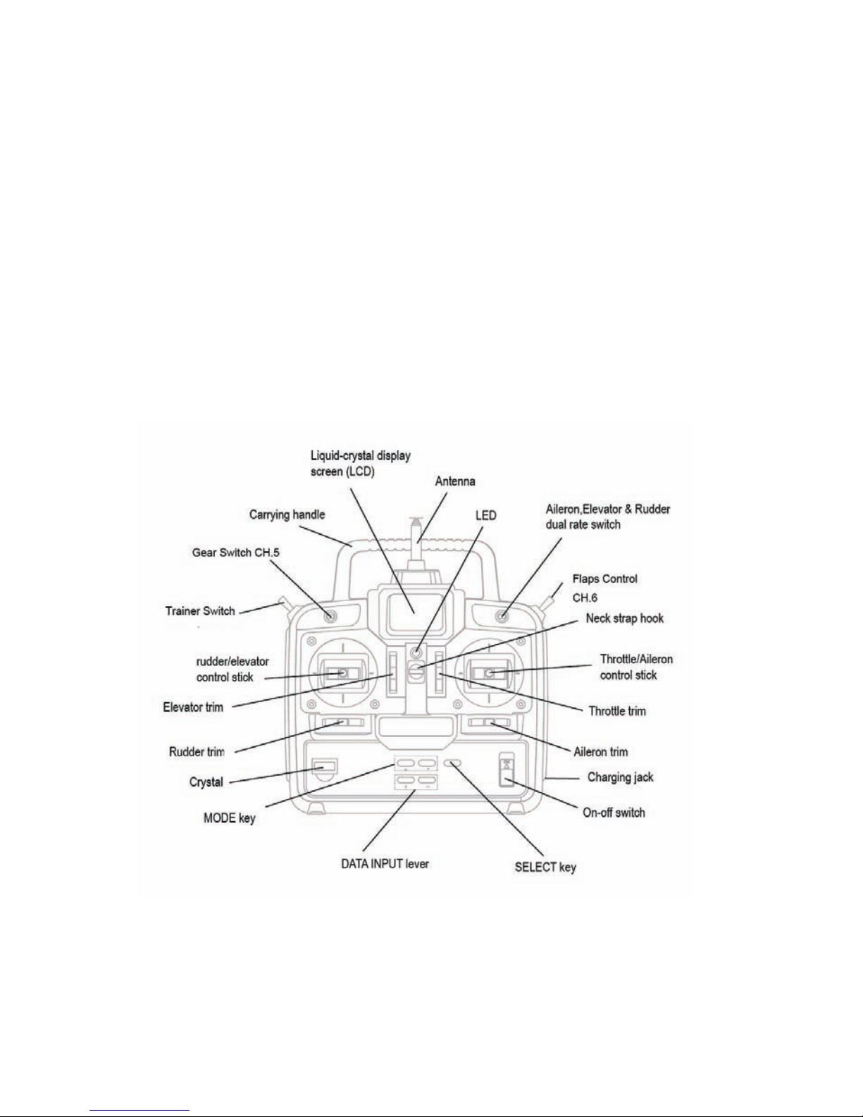
Transmitter controls
The diagram and explanations briefly describe the functions of the T6EAP transmitter. Full instructions on how to operate
the controls are provided beginning on page 7.
NOTE: The diagram shows a Mode 2 system as supplied.
DESCRIPTIONS:
Aileron, Elevator and Rudder dual rate switch Aileron, Elevator and Rudder dual rate switch
Use this switch to “flip” between two aileron, elevator and rudder control throw settings. The throws can be set up
however you prefer, but generally, when the switch is “up” the throws are greater (“high rate”) and when the switch is
“down” the throws are less (“low rate”). This switch also flips between exponential rates (if used).
Flap control dial/Channel 6 - This dial operates the servo connected to channel 6 in the receiver if your model has
flaps this is the control used to operate them.
Neck strap hook - Mounting point for optional neck strap.
Aileron/elevator control stick - Operates the servos connected to channel 1 (aileron) and channel 2 (elevator) in the
receiver.
3
Page 5
Trim levers (all) - Used to shift the neutral or center position of each servo as labeled in the diagram.
NOTE: The throttle trim lever is intended for fine tuning the throttle servo when the engine is at idle. Throttle trim does not affect
the throttle servo when the throttle control stick is all the way up (so idle r.p.m. can be adjusted without affecting throttle settings
through the rest of the stick movement.)
Aileron/elevator control stick - Operates the servos connected to channel 1 (aileron) and channel 2 (elevator) in the
receiver.
Trim levers (all) - Used to shift the neutral or center position of each servo as labeled in the diagram.
Charging jack - Port for charging the transmitter batteries with the included battery charger.
On-off switch - Turn on or off the transmitter.
DATA INPUT lever - Used to change the values of the various functions displayed on the LCD screen.
Liquid-crystal display screen (LCD) - Displays programming modes and values entered.
MODE key - Used to scroll through and display the ten or eleven(PCM) different functions.
SELECT key - Used to display the values for the current function.
Throttle/rudder control stick - Operates the servos connected to channel 3 (throttle) and channel 4 (rudder) in the
receiver.
Trainer switch - Operates the trainer functions. To operate as a trainer switch the transmitter must be connected to
another transmitter via. a trainer cord (available separately).
Retractable landing gear switch/Channel 5 - Switch operates the servo connected to channel 5 in the receiver if
your model has retractable landing gear this is the control used to extend and retract the gear.
Antenna - Radiates signals to the receiver. Never fly a model without fully extending the antenna or you may create
interference to other modelers and decrease operational signal range of the transmitter. The antenna may be removed
and replaced with another in case it is inadvertently broken.
RADIO INSTALLATION
Follow these guidelines to properly mount the servos, receiver and battery.
* Make certain the alignment tab alignment tab on the battery, switch and servo connectors is oriented correctly and
“keys” into the corresponding notch in the receiver or connectors before plugging them in. When unplugging
connectors, never pull on the wires. Always pull on the plastic connector instead.
* If any servo wires are not long enough to reach the receiver, servo extension wires (available separately) may be
used.
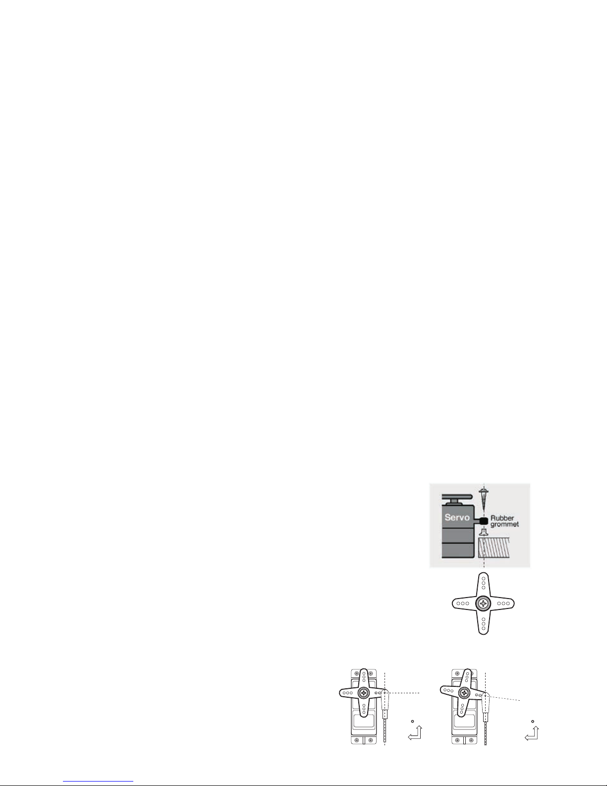
* Always mount the servos with the supplied rubber grommets rubber grommets. Do
not over tighten the screws. No part of the servo casing should contact the mounting
rails, servo tray or any
other part of the airplane structure. Otherwise, vibration will be transmitted to the servo
causing premature wear and/or servo failure.
* Note the small numbers (1, 2, 3, 4) molded into each arm on the 4-arm servo arms.
The numbers indicate how many degrees each arm is “off” from 90 degrees to correct
for minute manufacturing deviations from servo to servo.
1
234
* To center the servos, connect them to the receiver and turn
on the transmitter and receiver. Center the trims on the
transmitter, then find the arm that will be perpendicular to the
pushrod when placed on the servo.
1
234
1
2
3
4
90
Not 90
The trims on the radio should be centered.
4
Page 6
* After the servos are installed, operate each servo over its full travel and check that the pushrods and servo arms do
not bind or contact each other. Also make sure the controls do not require excess force to operate. If there is an
objectionable buzzing sound coming from a servo, there is probably too much resistance in the control. Find and
correct the problem. Even if there is no servo damage, excess battery drain will result.
IMPORTANT: NEVER cut the receiver antenna or mount it in the model folded back on itself. Doing so will change its
electrical length, possibly reducing the distance from the pilot that the model can be controlled (“range”).
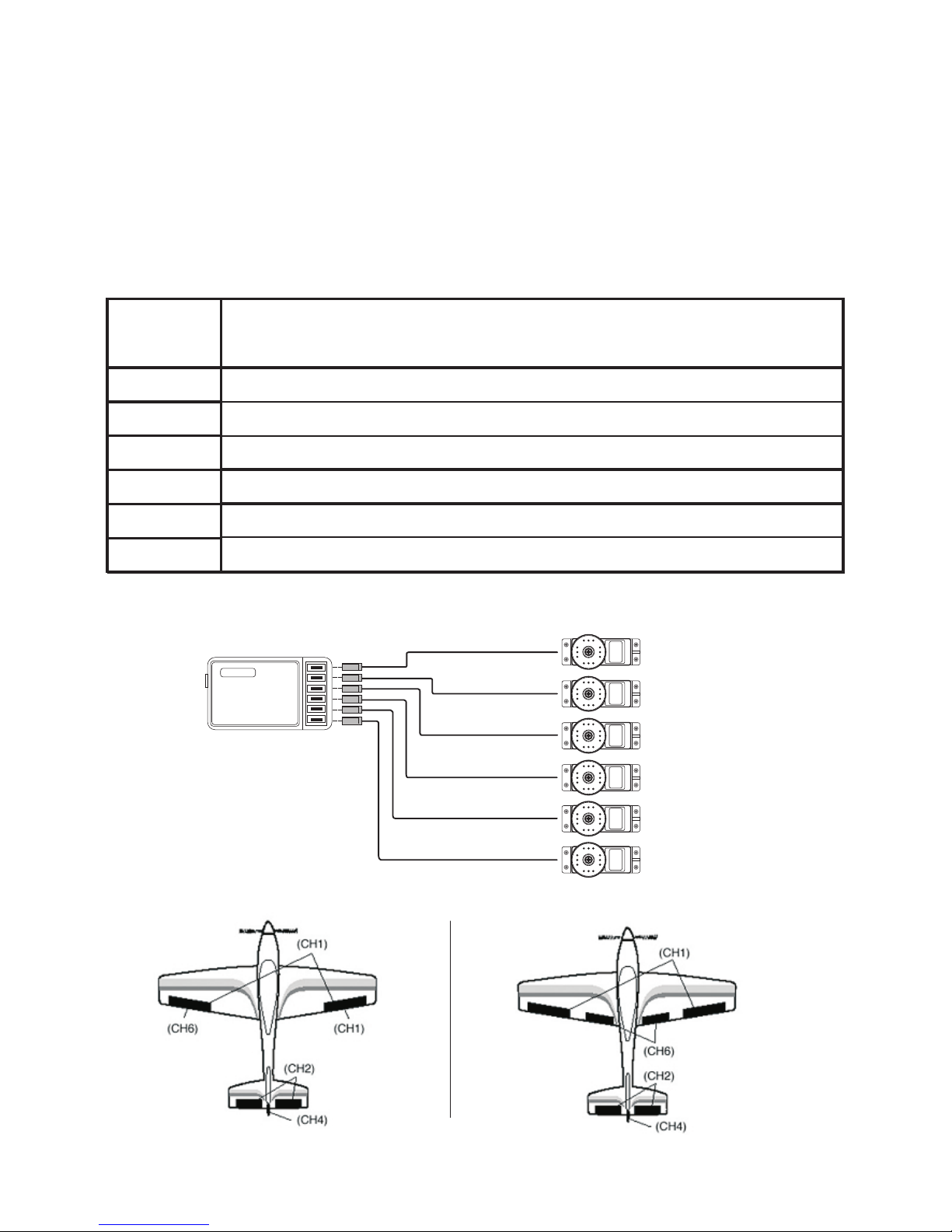
RECEIVER AND SERVO CONNECTIONS
Connect the servos to the receiver to perform the functions indicated:
Receiver
output
channel
Function
1 Aileron -or-right flaperon -or-right elevon (for tailless models)
2 Elevator -or-left ruddervator (for V-tail models) -or-left elevon (for tailless models)
3 Throttle
4 Rudder -or-right ruddervator (for V-tail models)
5 Retractable landing gear
6
Flap -or-left flaperon
The diagram shown is for aircraft models only. Additional servos may have to be purchased separately.
Aileron Servo
(Ch1)
6 Channal
Receiver
Elevator Servo
(CH2)
Throttle Servo
(Ch3)
Rudder Servo
(Ch4)
Gear Servo
(Ch5)
Flap (or 2nd
Flaperon) Servo
(Ch6)
Flaperon Mode(Dual Aileron Servos CH1&6)
Independent Aileron and Flap
5
Page 7

LIQUID CHIP DISPLAY (LCD) & PROGRAMMING CONTROLS
MDL 1
PPM
1
10.6V
Mode Button - use to
select desired function
while programm
Data Input Button - use
to input memory or setting.
Select Button-use to
select items within function
to be set or changed in the
screen
Power Switch
Modulation
Indicator
Transmitter
Battery Voltage
Current Model
Memory Number
Current Model
Memory Name
When the transmitter is initially turned on, the model memory number model memory number, model memory name
model, modulation type and transmitter battery voltage are displayed on the LCD screen. When prompted by the user,
the functions and settings stored in the memory can also be read on the screen. The user accesses the different
functions using the MODE and SELECT keys and changes the values and settings using the DATA INPUT lever. (This is
called programming!)
Note: Feel free to explore by scrolling through the programs and viewing the displays using the MODE and SELECT keys. The
MODE and SELECT keys only determine what will be displayed on the screen and will not change any of the settings. Only when
using the DATA INPUT lever will you be able to change any of the settings.
Model memory number and model name
The T6EAP stores model memories for six models. This means all the data (control throws, trims, end points, etc.) for
up to six different models can be stored in the transmitter and activated at any time (depending upon which model you
choose to fly that day). This eliminates the requirement for reconfiguring the transmitter each time you decide to fly a
different model with it! When the transmitter is turned on the model number, model name, modulation and the
transmitter voltage will be indicated on the LCD screen. Before every flight BE CERTAIN that the correct model number
for the model you intend to fly appears on the screen. If the transmitter is not operating the correct model, some (or all)
of the controls could be reversed and the travels and trims will be wrong.
Flying a model with the wrong program will result in a crash, so always be certain the model number and model name in the
transmitter is correct. One way to ensure this is to write the corresponding model number directly on the airplane, or attach a list
to the bottom or back of the transmitter.
Transmitter battery voltage
In addition to the model number, the LCD screen also displays the transmitter battery voltage. When the voltage
goes below approximately 8.5 Volts the “battery” icon will flash and the low-battery alarm will continuously “beep”
until the transmitter is turned off. When the low-battery alarm sounds you will have approximately four minutes (or
less) to land your model before losing control. You should never allow the transmitter voltage to become this low while
flying, but if it does, land immediately.
9.4 Volts - No more flying until recharge.
8.9 Volts - Land as soon as safely possible.
8.5 Volts - Emergency- Land immediately! Emergency- Land immediately!
SUGGESTED GUIDELINES
6
Page 8

PROGRAMMING THE T6EAP RADIO
Anytime you wish to view or change any of the current settings in the transmitter, the programming mode must first be
entered by, of course, turning on the power, then by pressing the 2“MODE” keys simultaneously and holding them
down for one second. Once “in the program” the MODE key will be used to scroll through all of the functions (model
number/ data reset/ model name, reversing, dual rates/ exponentials, end point adjustments, trim, programmable mix,
“flaperon” mixing, “v-tail” mixing, “elevon” mixing, flap trim) and the SELECT key will be used to view the settings
within the function. When a data change is actually required the “DATA INPUT” button will be used to increase or
decrease the value of the item displayed, thus making the change.
You can return to the “home” screen (where the model number and battery voltage is displayed) by pressing the 2”MODE” keys
simultaneously and holding them down for one second.
Model Select / Data Reset / Model Name
MODL - Model select function
To select model memory:
1. Access the Model Select function in the programming mode (by pressing the 2 MODE
keys simultaneously and holding them down for one second). The number for the current,
active model will be blinking.
2. To activate a different model memory press the DATA INPUT lever until the desired
model number appears.
3. Now the model has been selected. All programming inputs from this point forward will
affect only the model number on the screen (until another model number is selected).
PPM
MODL
1
RCST Data reset function
All the data for any model memory can be reset to the original factory defaults. Often this function is done to get a “fresh
To reset data:
1. Access the Model Select function in the programming mode (by pressing the 2 MODE
keys simultaneously and holding them down for one second). Use the DATA INPUT lever to
select the model memory you wish to reset.
2. Once the desired model number is displayed on the screen, press the SELECT key. A
“REST” will appear on the screen.
PPM
REST
1
CLR
3. Push DATA INPUT upward or downward for about 2 seconds to clear and reset the memory. “CLR” blinks first, and
then it stops blinking with a sound. Now the model data is reset to the initial setting that is the default value set at the
factory.
The existing modulation setting is not reset. If the power switch is turned off while reset is underway, the data may not be reset.
CAUTION: Resetting the current model memory will permanently erase ALL programming information for that model.
The data cannot be recovered. Do not reset the model unless certainly you want flushing-out that memory and start from
scratch.
When actually setting up a model you should have the model in front of you with the power on so you can actually see the
effects of your programming inputs and measure the control throws.
Model name function
Assign a name to the model memory. By giving each model a name that is immediately recognizable, you can quickly
select the correct model, and minimize the chance of flying wrong model memory that could lead crash.
PPM
MDL1
1. Access the Model Select function in the programming mode (by pressing the 2 MODE
keys simultaneously and holding them down for one second). Use the DATA INPUT lever
to select the model number you wish to change.
2. Once the desired model number is displayed on the screen, press the SELECT key. A
NAME will appear on the screen.
7
Page 9

3. Choose a character for the first digit by using DATA INPUT lever. Then move to the next digit by pressing the SELECT
key and choose a character in the same way. Continue choosing characters for the third and fourth digits. You can use
up to four characters for the name.
REVR - Servo Reversing
The servo reversing function is used to change the direction that a servo responds to a control input from the transmitter
(stick, dial or switch). After using the reversing function, check all the controls on the model to be certain be certain
they are operating in the correct direction and that you did not inadvertently reverse a servo other than the one intended.
Reversing the wrong servo (and not checking the response of the controls before each flight) may be the most common
cause of a crash!
PPM
Revr
1
NOR
REV
CH
To reverse a servo:
1. Enter the programming mode and use the MODE key to access the REVR function.
2. Use the SELECT key to select the channel you wish to reverse.
3. Push the DATA INPUT lever downward to reverse the servo (REV), or push the lever
upward to make the servo operate normally (NOR). The arrow will indicate the condition of
the servo (normal or reversed). In the diagram channel 1 (aileron) is “normal” (not
reversed).
4. Use the SELECT key to display other channels to be reversed.
Dual Rates / Exponential Settings
The aileron, elevator and rudder dual rates on the T6EAP are simultaneously activated by the dual rate switch. The
amount of travel decrease for each control may be set between 0% and 100% of the values set for the end points.
Note: It is possible to set a dual rate value to zero, thus causing no response from that channel. If the dual rates are inadvertently set to
zero, a crash could result.
Note: When performing initial model setup, the E.P.A.s should be set prior to setting the dual rates. When setting the E.P.A.s for the first
time on a new model, the dual rates should be set to 100%.
PPM
1
CH
100
%
D/R - Dual Rate Settings
To set the dual rates:
1. Enter the programming mode. Access the “D/R” screen with the MODE key.
2. Select the channel to be adjusted (1-aileron, 2-elevator, 4-rudder) by pressing the
SELECT key until the desired channel number the left side on the screen.
3. Place the dual rate switch in the desired position for the value you wish to change.
(Generally, pilots prefer to have the switch in the “up” position for the high rate, and in the “down” position for the low
rate.)
4. Change the dual rate value using the DATA INPUT lever until the desired control throw is achieved. If you wish to
change the control throw when the switch is in the other position as well, flip the switch, then use the DATA INPUT lever
to change the throw.
5. Repeat the procedure for the other dual rate (channel 2-elevator, 4-rudder).
EXPO - Exponential Settings
The “exponentials” are in the same function as the dual rates. (Pressing the MODE key will take you to the next function
which is End Point Adjustments). The same as dual rates, “expos” can be set for both switch positions. Negative
exponential (-) decreases initial servo movement. Positive exponential (+) increases initial servo movement. The
exponential “curve” may be set anywhere between -100% and +100%.
PPM
1
CH
0
%
EXPO
1. Enter the programming mode. Access the “D/R” screen with the MODE key.
2. Access the “EXPO” screen with the SELECT key.
3. Select the channel (1-aileron, 2-elevator, 4-rudder) you wish to set by pressing the
SELECT key. The active channel number will be displayed on the screen.
8
Page 10

4. Position the dual rate switch where desired for the value you wish to change.
5. Enter the amount of exponential with the DATA INPUT lever. (As stated above, an exponential value with a “-” in front
of it makes the initial servo movement less, or “softer.”)
6. Flip the switch to the other position to enter the exponential value for that switch position.
7. Repeat for the settings on the other channel.
1
234
0- 120%
At 120%
At 100%
EPA - End Point Adjustment
Note: Since changing the “end points” will also change the dual rates, the end points should be set prior to setting the dual rates. If you
set the dual rates first, and then go back and change the end points, the dual rate throws will also change.
The EPA function is designed to “fine tune” the servo throws in cases where
changing the pushrod hookup will not achieve the correct throw. The pushrods
should first be connected to the servo arms and control horns so the correct, or
near correct control surface throw will be achieved. THEN the EPAs may be used
to make small changes in the servo throw until the desired control throw is
achieved. The control throws should be set up so that the “end points” are as near
to 100% as possible. If the EPA values must be set below 70% or above 120% to
get the desired throw, you should strongly consider changing the pushrod
connections so the values can be set closer to 100%. (When the EPA is set to
100% the maximum servo throw for channels 1, 2, 3 & 4 is approximately 40 °
and approximately 55° for channels 5 & 6.)
To set the end points:
1. Enter the programming mode and use the MODE key to access the “EPA” screen. The
channel number being adjusted will show on the left side on the screen and the % symbol
will be flashing.
2. To change the RIGHT aileron throw move the aileron stick to the right, then push the
DATA INPUT lever up or down to change the value and the throw.
PPM
1
CH
100
%
Epa
3. Move the stick to the left and use the DATA INPUT lever to change the LEFT aileron throw.
4. Use the SELECT key to display the other channels and set the other end points. Notice that moving the stick (or switch
or dial) from one end to the other changes the value displayed and the position of the arrow for that “end” of the control
input.
TRIM - Trim Settings
There are four trim levers (“trims”) on the front of the transmitter. Three of the trims are for adjusting the neutral position
of the aileron, elevator and rudder servos. The fourth trim is for setting the idle r.p.m. of the engine when the throttle
stick is all the way down. The intended use of the trims is to make small servo adjustments, in flight, to get the model
properly “trimmed” (so it will fly straight-and-level). Because the trims are intended to be used while the model is in
flight, you do not have to “enter the program” to adjust the trims. Simply push or pull on the trim levers while flying and
the neutral position of the servos will shift. Keep in mind that you should start out with the control surfaces centered
when the servos are centered and the trims are “zeroed” (or near zero). THEN you can adjust the trims once airborne.
Center the servos:
1. Turn on the transmitter and receiver. Operate the controls to make sure the servos respond in the correct direction.
Use the reversing function to reverse any servos necessary.
2. Center the throttle control stick.
3. Place the servo arms on the servos so they are perpendicular to the pushrods (see page 5). It is okay to cut off any
unused servo arms.
4. Connect the pushrods to the control surfaces. Adjust the length of the pushrods until the control surfaces are
centered when the servos are centered.
Note: The throttle trim affects the throttle servo only when the throttle stick is below “1/2 stick.” This way, the final closing of the
carburetor can be adjusted without affecting the servo throughout the rest of the range.
9
Page 11

To adjust the trim settings:
Once the servos and control surfaces have been connected and the control throws have been set using the end points
and dual rates, get the model airborne. Adjust the trims as necessary to get the model to fly straight-and-level. If much
trim is required on any one control it is a good idea to readjust the pushrods so the trims can be returned to neutral
(zero). Adjusting the trims with the trim levers changes the servo's position in increments of “4.” If finer adjustments
are required, land the model, then enter the program as described below to adjust the trims in increments of “1.”
1. Enter the programming mode and use the MODE key to activate the TRIM menu.
2. Press the SELECT key to display the channel to be adjusted (the figure shows trim
adjustment for CH1).
3. Adjust the trim using the DATA INPUT lever. Note that initially, the values change in
increments of “1,” but if the DATA INPUT lever is held long enough the values will change
more rapidly.
4. Repeat the steps for other channels that require trim adjustments.
PPM
1
CH
0
Trim
PMIX - Programmable Mixer
Unlike the “wing mixing” function (explained later) where the channels to be mixed are factory-set, the T6EAP also
contains one programmable mix for you, the pilot determine the channels to be mixed. This could be used to correct
unwanted flight tendencies (by mixing rudder to aileron, or aileron to rudder for example).
PPM
PMIX
Inh
To set up a programmable mix:
1. Enter the programming mode. Access the “PMIX” screen with the MODE key.
PPM
PPM
PPM
PPM
PMIX
Mas
Slv
PMIX
On
Ch1
Ch4
0
%
2. Push the DATA INPUT lever upward. This will cause the flashing “INH” display to change
to a flashing “ON” display.
3. Push SELECT key to call the screen for selecting channels to control “MAS” (Master)
mixing. Then select the channel by pushing DATA INPUT lever. Channel 1 (aileron) in this
figure is assigned to the master.
4. Push SELECT key to call the screen for selecting channels to control “SLV” (Slave)
mixing. Then select the channel by pushing DATA INPUT lever. Channel 4 (rudder) in this
figure is assigned to the slave.
5. Press the SELECT key twice to display the flashing % sign. Use the DATA INPUT lever to
set the percentage of mixing from -100% to +100% (depending on the direction and
distance you wish the slave servo to move).
6. Observe how the controls on the model respond to be certain you have achieved the correct mix and that the throws
are as desired.
10
Page 12

Wing Mixing Type Selection
With the programmable mix (previously described) the user determines the two channels to be mixed. The wing mixing
function is another mix that may be used, but the channels mixed are predetermined. There are three different wing
mixing functions to select from:
Aileron Operation
Flap Operation
*If necessary, use the Servo Reversing function to achieve the correct direction of servo throws.
FLPR- Flaperon mixing
This function allows the ailerons to be used both as ailerons and as flaps. The flap control dial (CH 6) operates the flap
function. To use flaperon mixing both ailerons must be operated by separate servos.
PPM
Flpr
Inh
To activate flaperon mixing:
1. Connect the aileron servo in the right wing to channel 1 (aileron) in the receiver and
connect the aileron servo in the left wing to channel 6 (flaps) in the receiver.
2. Enter the programming mode. Access the “FLPR ” screen with the MODE key.
PPM
Flpr
PPM
Flpr
On
PPM
Flpr
0
%
You cannot set “Flaperon ” mixing when “Elevon ” mixing has already been set. In order to
enable “Flaperon ” mixing, you first need to cancel “Elevon ” mixing. However, it is
allowed to use “Flaperon” and “V-Tail” mixing simultaneously.
3. Push the DATA INPUT lever upward. This will cause the flashing “INH ” display to
change to a flashing “ON ” display. Now the mixing is on.
4. If needed to set ailerons differential. Press the SELECT key to display the flashing “%”
sign. Use the DATA INPUT lever to set the percentage of ailerons differential from -100%
to +100% (The “-” direction indicates decreasing amount of movement toward the
upward from the aileron surface, while “+” direction indicates decreasing amount of
movement toward the downward from the aileron surface.)
5. Once this mix has been activated, move the servos to their full extremes to make certain they are not overdriving the
controls. If necessary, adjust the linkages to achieve the correct control throws.
FLTR - Flap trim
The Flap Trim function is used to specify the amount of flap travel produced moving the flap control (the Flap control
dial). As normal flap control dial will be inhibited to use if the flaperon function is activated, the Flap Trim function
should be activated if you need to control flap by Flap control dial.
To activate flap trim:
1. Enter the programming mode. Access the “FLTR” screen with the MODE key.
PPM
Fltr
Inh
11
Page 13

PPM
Fltr
On
PPM
Fltr
0
%
2. If “INH” is blinking, push DATA INPUT lever upward. Then you will see that the blinking
“INH” changes to “ON”. Your flap trim is now turned on.
3. Set the travel of the flap control dial at between -100% and +100% by using DATA INPUT
lever.
V-TL V-tail mixing
Intended for V-tail aircraft (such as a Beechcraft Bonanza), V -tail mixing allows the ruddervators to operate both as
rudders and elevators. The same as the other mixes, V -tail mixing requires that each ruddervator be operated by a
separate servo.
Ch2 Ch4
Up Elevator
Ch2 Ch4
Left Rudder
(View from rear)
*If necessary, use the Servo Reversing function to achieve
the correct direction of servo throws.
To activate V-tail mixing:
1. Connect the left ruddervator servo to channel 2 (elevator) in
the receiver and connect the right ruddervator servo to channel
4 (rudder) in the receiver.
PPM
V-tl
Inh
PPM
PPM
PPM
V-tl
V-tl
V-tl
On
50
2. Enter the programming mode. Access the “V-TL ” screen with the MODE key.
You cannot set “V-tail ” mixing when “Elevon ” mixing has already been set. In order to
enable “V-tail ” mixing, you first need to cancel “Elevon ” mixing. However, it is allowed to
use “V-Tail” and “Flaperon” mixing simultaneously.
3. Push the DATA INPUT lever upward. This will cause the flashing “INH ” display to
change to a flashing “ON ” display. Now the mixing is on.
4. Next you may the elevator setting. Press the SELECT key to display the “CH2” and
flashing “%” sign. Use the DATA INPUT lever to set the percentage of elevator travel rate
from -100% to +100%
5. Next you may the rudder setting. Press the SELECT key to display the “CH4” and
flashing “%” sign. Use the DATA INPUT lever to set the percentage of rudder travel rate
from -100% to +100%
6. Once this mix has been activated, move the servos to their full extremes to make certain
they are not overdriving the controls. If necessary, adjust the linkages to achieve the
correct control throws.
2
%
CH
PPM
V-tl
50
4
%
CH
12
Page 14

ELVN Elevon mixing
Intended for tailless, “flying wing” models such as delta wings and flying wings,
elevon mixing mixes channel 1 (aileron) to channel 2 (elevator) allowing the
elevons to operate in unison (as elevators) or in opposition (as ailerons). This
function requires that each elevon be operated by a separate servo.
To activate elevon mixing:
1. Connect the servo in the right wing to channel 2 (elevator) in the receiver and
connect the servo in the left wing to channel 1 (aileron) in the receiver.
PPM
Elvn
Inh
PPM
PPM
PPM
Elvn
Elvn
Elvn
On
50
1
%
CH
PPM
Elvn
50
2
%
CH
2. Enter the programming mode. Access the “ELVN” screen with the MODE key.
You cannot set “Elevon” mixing when “Flaperon” or “V-TL” mixing has already been
set. In order to enable “Elevon” mixing, you first need to cancel both “Flaperon” and
“V-tail” mixing.
3. Push the DATA INPUT lever upward. This will cause the flashing “INH” display to
change to a flashing “ON” display. Now the mixing is on.
4. Next you set the left wing to channel 1 (aileron) setting. Press the SELECT key to
display the “CH1” and flashing “%” sign. Use the DATA INPUT lever to set the
percentage of elevator travel rate from -100% to +100%
5. Next you set the right wing to channel 2 (elevator) setting. Press the SELECT key to
display the “CH2” and flashing “%” sign. Use the DATA INPUT lever to set the
percentage of rudder travel rate from -100% to +100%
6. Once this mix has been activated, move the servos to their full extremes to make certain they are not overdriving the
controls. If necessary, adjust the linkages to achieve the correct control throws.
13
Page 15

PPM
MODL
I
PPM
MODL
6
[Model 2- 5]
PPM
REST
CLR
PPM
MOL 1
PPM
REVR
I
CH
[CH 2-5]
PPM
REVR
6
CH
PPM
D/R
I
CH
100
%
PPM
D/R
2
CH
100
%
PPM
D/R
4
CH
100
%
PPM
EXPO
1
CH
0
%
PPM
EXPO
2
CH
0
%
PPM
EXPO
4
CH
0
%
[CH 2-5]
PPM
EPA
I
CH
100
%
PPM
EPA
6
CH
100
%
[CH 2-3]
PPM
TRIM
I
CH
0
%
+
-
PPM
TRIM
4
CH
0
%
+
-
PPM
PMIX
Inh
PPM
PMIX
On
PPM
Mas
Ch1
PPM
Slv
Ch4
PPM
PMIX
0
%
PPM
Flpr
Inh
PPM
Flpr
On
PPM
Flpr
0
%
PPM
Fltr
Inh
PPM
Fltr
On
PPM
Fltr
0
%
PPM
V-tl
Inh
PPM
V-tl
On
PPM
V-tl
50
2
%
CH
PPM
V-tl
50
4
%
CH
PPM
Elvn
Inh
PPM
Elvn
On
PPM
Elvn
50
1
%
CH
PPM
Elvn
50
2
%
CH
To enter or leave Programming Mode, press 2 MODE keys simultaneously for one second.
To change the Stick Mode, turn on the transmitter holding both 2 MODE keys down simultaneously.
Use the DATA INPUT lever to display the desired stick mode.
FLOW CHART
14
MODE
SELECT
DATA INPUT
MODE KEY
Page 16

Trainer switch
To utilize the trainer function, the appropriate trainer cord (available separately) and a second Futaba transmitter
(usually provided by your flight instructor or R/C club) will be required. When two radios are connected with the trainer
cord, they are both capable of operating the model, but it's usually best for the instructor to hold the radio that has been
setup for the plane to be flown (as it is already programmed to fly the model). When the instructor holds the trainer
switch on his radio, the student will have control. When the instructor wishes to regain control he simply releases the
switch. Then he will have immediate, full control.
To use the trainer cord:
1. It is best for the instructor to use the transmitter that is already set up for the model to be flown.
2. If the student's radio has PCM/PPM capability, set it to PPM.
3. If the student's radio has a plug-in RF module, remove the module.
4. Collapse the student's antenna and fully extend the instructor's antenna.
5. With the transmitters off, connect the trainer cord to both radios. (On the T6EAP the trainer jack is in the center of the
rear of the case.) Do not force the plug into the transmitter and note that the plug is “keyed” so it can go in only one way.
6. Turn on the instructor's transmitter. DO NOT turn on the students transmitter it will automatically “power up,” but will
not transmit a signal. Set the servo reversing and trims of the student's radio to match that of the instructor's.
7. Turn on the receiver switch in the model. Depress the trainer switch on the instructor's radio. Use the student's radio
to operate the controls (ailerons, elevator, rudder, etc.) and observe how they respond. Make any adjustments necessary
to the student's transmitter to get the controls to respond correctly.
8. Check to see that the trims are in “sync” by toggling the trainer switch back and forth a few times. The controls on the
model should remain stationary. If the controls do not remain stationary, this indicates that the trim settings on the
student's radio do not match those on the instructor's radio. Adjust the student's trims as necessary.
Note: When the instructor initially depresses the trainer switch on his transmitter, there will be a one-second delay
before the student takes control. In most situations this momentary delay will go unnoticed.
Optional Flap control lever (Option)
When the flaperon mixing function is activated, the optional flap control lever flap control lever can be used to set
maximum flap deflection by mechanically limiting the dial. This will prevent inadvertently retracting the flaps beyond
their full, "up" position. To use the flap control lever, turn the flap dial until the flaps are retracted (up). Place the flap
control lever over the dial so that the arm is contacting the transmitter case. This will limit rotation of the dial so the
flaps cannot go up any farther.
Adjustable-length control sticks
The control stick length is adjustable to make the transmitter more comfortable to hold and operate. To adjust the length,
hold the locking piece (B) locking piece (B) and turn the stick tip (A) stick tip (A) counterclockwise. Turn the locking
piece B up or down to lengthen or shorten the stick. When the length is suitable, lock the stick in position by turning
locking piece B counterclockwise.
OTHER 6EXAP FUNCTIONS
Changing the 6EXAP stick mode
The transmitter may be operated in four different stick “modes” (1, 2, 3 & 4).
The modes determine the functions that will be operated by control sticks.
To change the mode, simultaneously depress the MODE and SELECT keys,
then turn on the power. The current mode will appear on the LCD screen.
Push the DATA INPUT lever up or down to change the mode. If a mode is
selected that moves the throttle control to the right stick, the throttle detent
mechanism will have to be moved as well.
15
Page 17

Each transmitter has an individually assigned, unique ID code. In order to start
operation, the receiver must be linked with the ID code of the transmitter with
which it is being paired. Once the link is made, the ID code is stored in the
receiver and no further linking is necessary unless the receiver is to be used
with another transmitter. (For T/R set, the link is already done at factory. When
you purchased another receiver, this procedure is necessary; otherwise the
receiver will not work.
1. Place the transmitter and the receiver close to each other within one (1) meter
2. Turn on the transmitter.
3. Check the LED that is placed on the back side of the transmitter to see if the
RF signal is active. When the green LED is ON solid, the RF signal is being sent.
4. Turn on the receiver.
5. Press down the "ID SET" switch for more than one second, and release the
switch. The receiver starts the linking operation.
6. When the linking is complete, the LED in the receiver will change to solid
green. Please confirm that the servos will now operate by your transmitter.
LINK PROCEDURE
ID SET
16
Page 18

T6EAPT6EAP
For Radiolink T6EAP 6-channel
PPM(FM) modulation
Radio control system for aircraft
INSTRUCTION MANUAL
Technical support available at : http://www.radiolink.com.cn
Radiolink Electronic
 Loading...