

Page 1
Instructions
Read and retain carefully for as long as the product is being used. It contains vital information on the operation
and installation. This booklet should be regarded as part of the product.
If you are just installing the Alarm, this booklet must be given to the householder. This booklet is to be given to
any subsequent user.
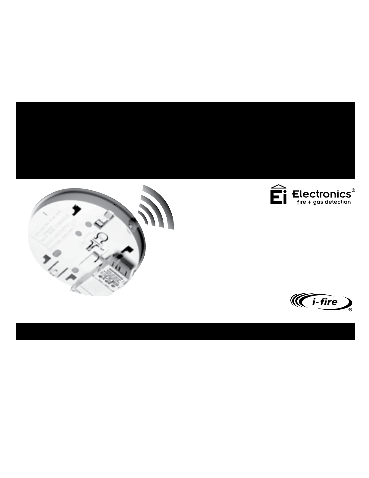
Model: Ei168RC
RadioLINK
Alarm Base
Page 2

Contents
1. Overview ........................................................................................................
2. Quick install guide .....................................................................................
3. Installation ...................................................................................................
4. Troubleshooting the RF link ....................................................................
5. Checking & maintaining the alarm system ........................................
6. Technical specification .............................................................................
7. Guarantee ....................................................................................................
8. Limitations of radio communications ...................................................
9. Getting the RadioLINK Base serviced ....................................................
2
3
6
8
17
19
22
23
23
25
Page
Page 3
1. Overview
This version of the Ei168RC retains all the functionality of previous generations but
has some additional features. It can be easily distinguished from previous versions by
the blue LED on the side which replaces the amber LED.
The primary function of the RadioLINK base is to interconnect all Alarms in the system,
i.e. when one Alarm senses fire, the Ei168RC base attached to that Alarm will transmit
an RF signal that will activate the sounders in all the other Alarms.
The Ei168RC also supports Remote Control (RC) functionality. If the system has been
fitted with one or more Remote Controllers or switches (
See Works with table)
.
3
Page 4
4
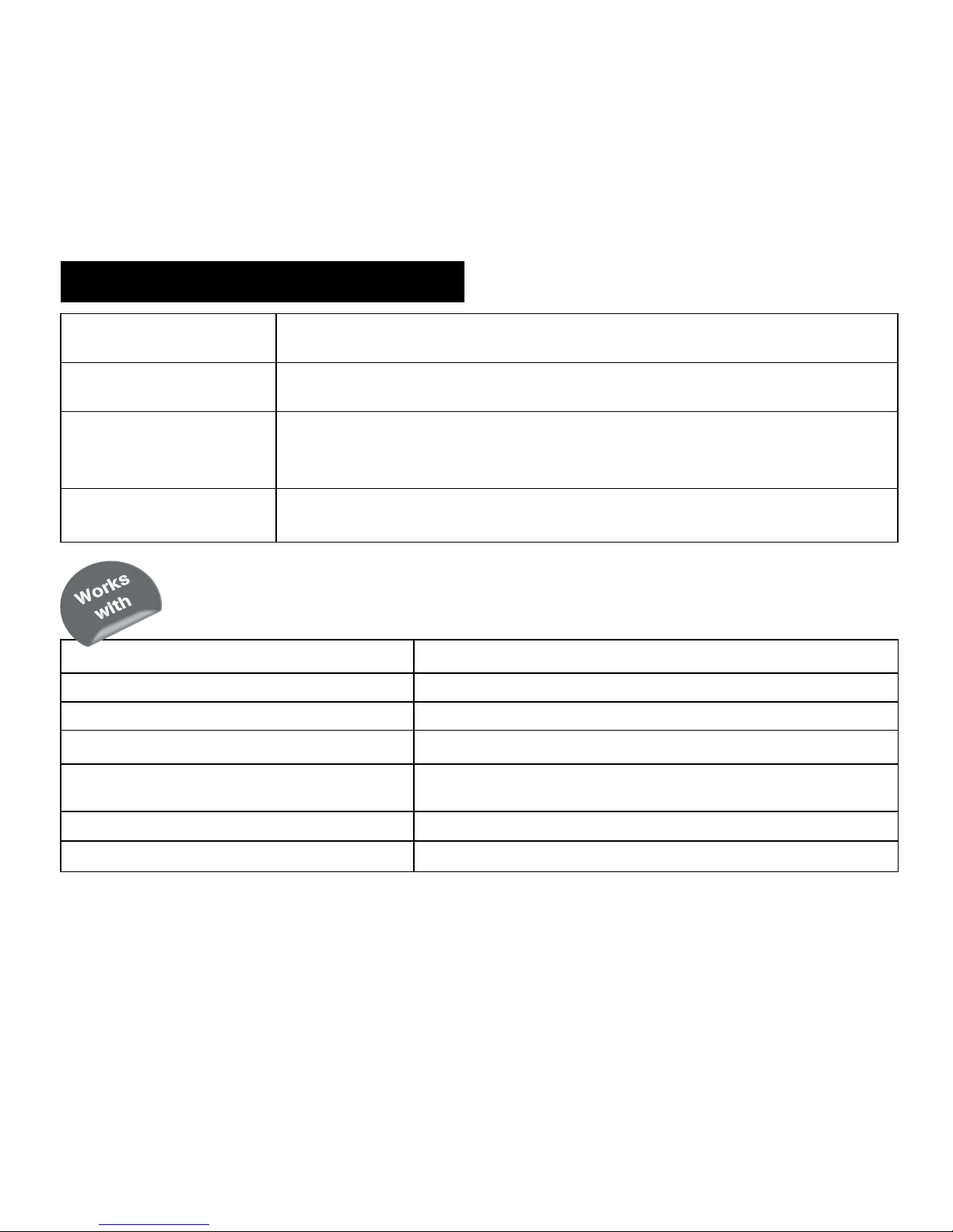
Function
Remote Testing
Description
All the Alarms can be tested from a centralised location
Remote LocatingThis will silence all the Alarms in the system except
the one sensing the fire
Remote Silencing This will silence all the Alarms in the system
Model No. - Alarms Comment
Ei160RC & Ei140RC Series RadioLINK interconnect and Remote Control (RC)
Ei2110 Multi-Sensor Fire AlarmRadioLINK interconnect and Remote Control (RC)
Model No. - RadioLINK Devices
Ei450 Remote Controller
Remote Controller for Ei2110, Ei160RC Series, Ei140RC Series
when fitted with Ei168RC RadioLINK bases
Ei408, Ei428 & Ei428SK Input and output relay modules
Ei407 Manual Call Point
Remote Control Functions
Page 5
5
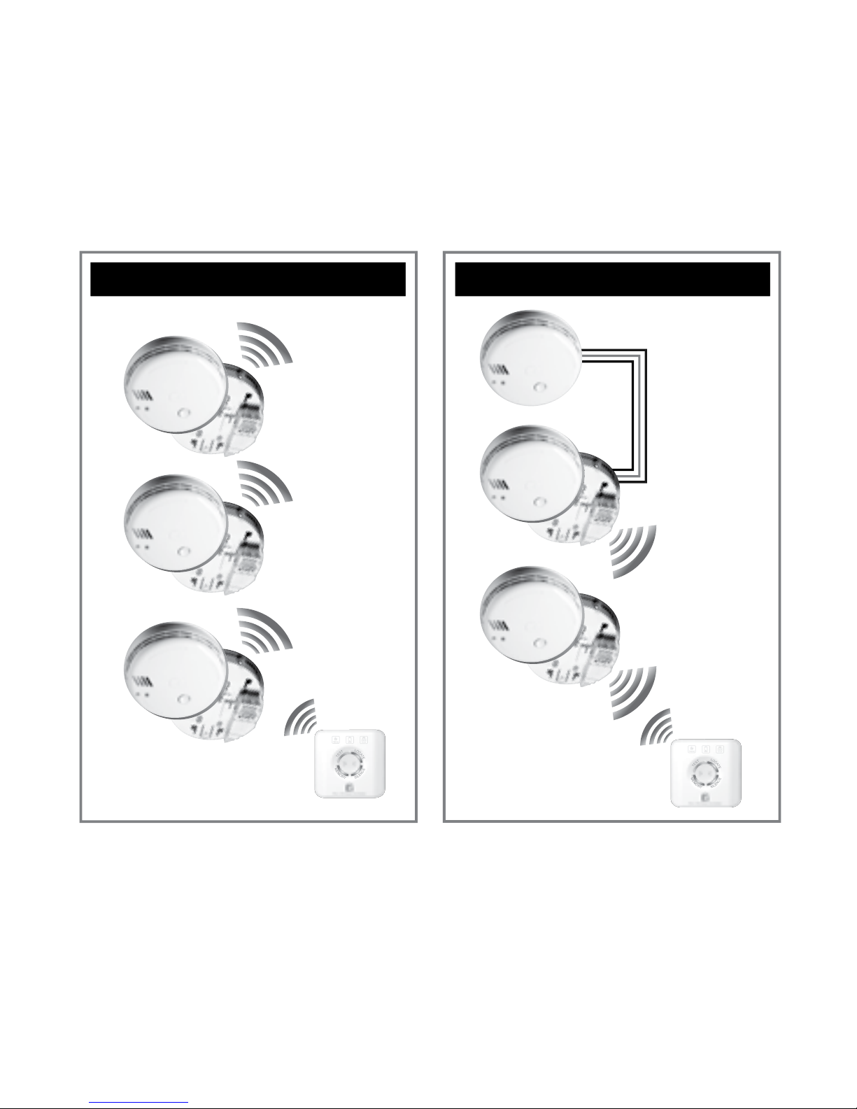
RadioLINK System
Mixed Wired &
RadioLINK System
Alarm Controller
Hardwired
interconnect
Wireless
interconnect
Alarm Controller
In this configuration the alarm controller must be a RadioLINK device.
It is not possible to control the system from the hardware interconnect side
Page 6
2. Quick Install Guide
The Ei168RC RadioLINK Base must be installed by a qualified electrician.
The maximum number of RadioLINK Alarms in each system is 12.
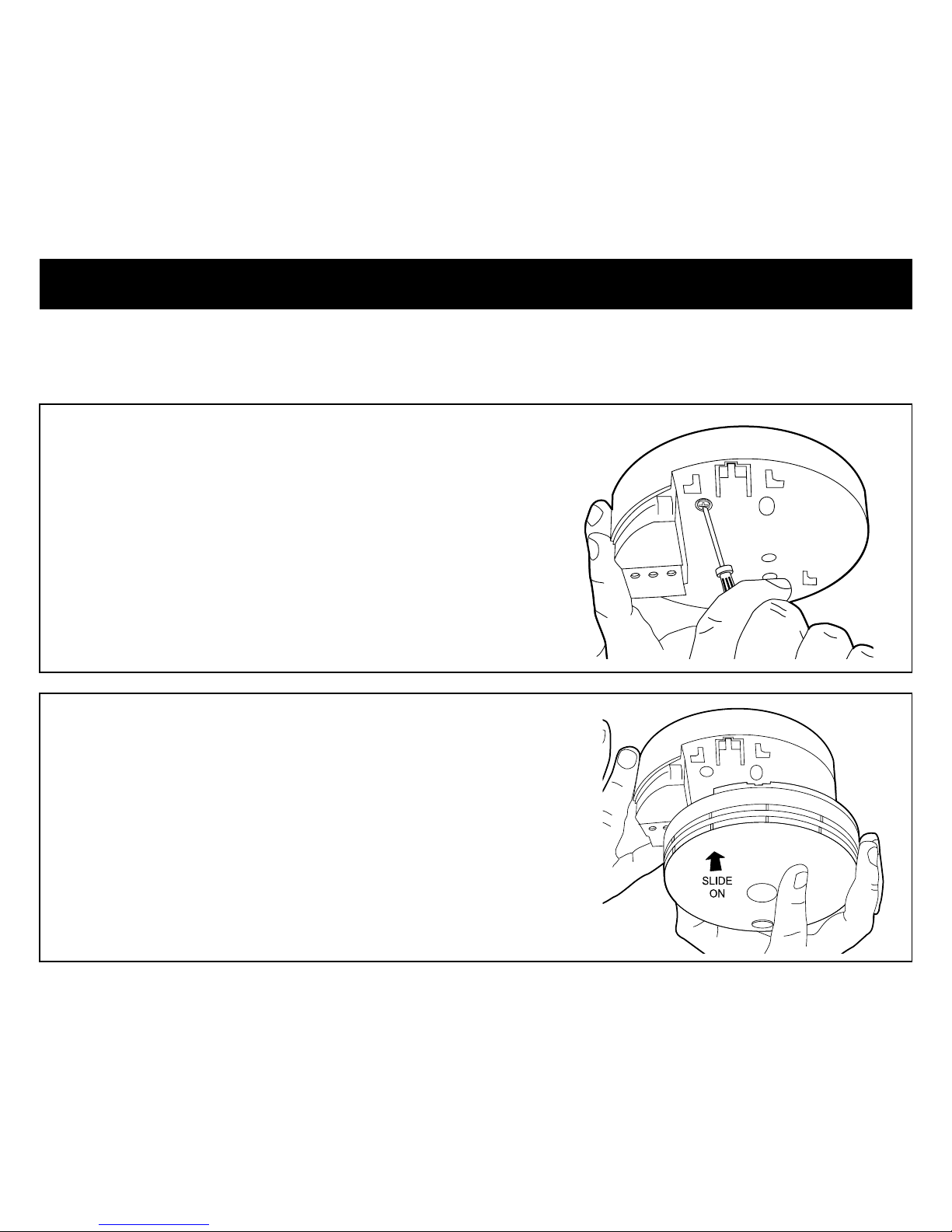
Install each RadioLINK Base in the centre of the
ceiling at least 0.30m from light fittings as per
the Smoke/Heat Alarm instructions and connect
to nearest mains circuit.
Slide Alarm on to the Ei168RC RadioLINK Base.
This will automatically activate the rechargeable
back-up cells in the base.
Repeat this procedure for all Alarms in the
system.
6
Page 7
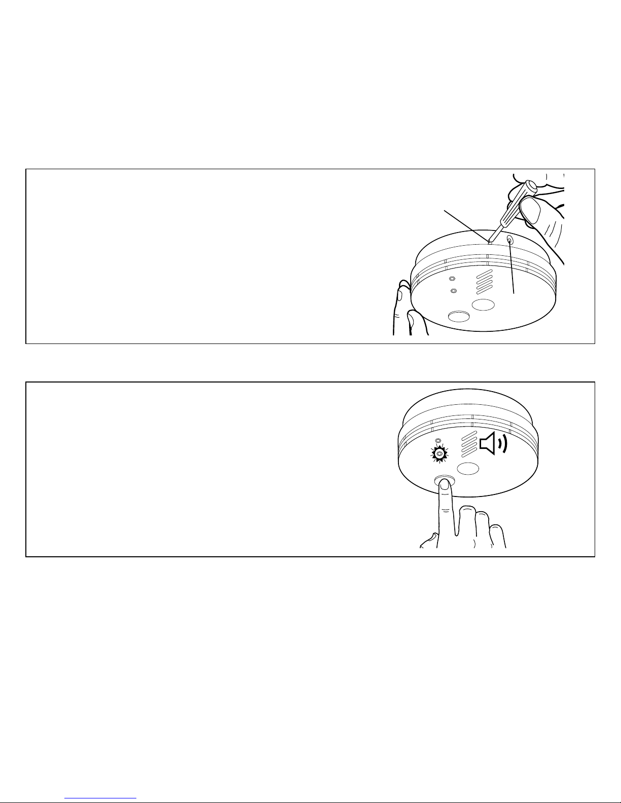
To House Code, insert a small screwdriver
into the House Code switch slot and remove
immediately when blue light comes on. Repeat
this for all alarms in the system. This must be
completed as quickly as possible to activate the
House Code mode and ensure the system only
communicates with itself and not neighbouring
systems.
It is essential that the RadioLINK Bases are House Coded.
Press and hold the Button to test each Alarm.
Check that the red light is flashing, the horn is
sounding. To ensure the Alarm is communicating
with others check that the blue light comes on
for approx 3 seconds.
This guide is for quick referencing only. You must read the user manual
thoroughly before installation and use.
7
INSERT SCREWDRIVER TO
TURN ON HOUSE CODE SWITCH
BLUE LIGHT
Page 8
3. Installation
8
Mains operated products should be installed by a qualified
electrician as per the requirements for Electrical Installations
published as IEE Wiring Regulations – BS7671 current edition.
Failure to install this unit correctly may expose the user to
shock or fire hazards.
This unit is not waterproof and must not be exposed to dripping
or splashing liquids.
Mixing the Live and Neutral connections will damage the alarm.
Ensure that the same colours are used throughout the
premises for Live, Neutral and Interconnect wires (if used).
WARNING
WARNING
WARNING
Alternative Energy Sources (Wind, Solar, UPS, etc.).
This product is designed to be connected to a Pure or True
Sine Wave 230 Vac supply. If connecting to a power source
that utilises an inverter, e.g. PV solar panel or UPS, the Total
Harmonic Distortion (THD) must be less than 5%. If in doubt
check with manufacturer of the inverter.
Light Dimmer Circuits
This product must not be powered from a light dimmer circuit.
Page 9
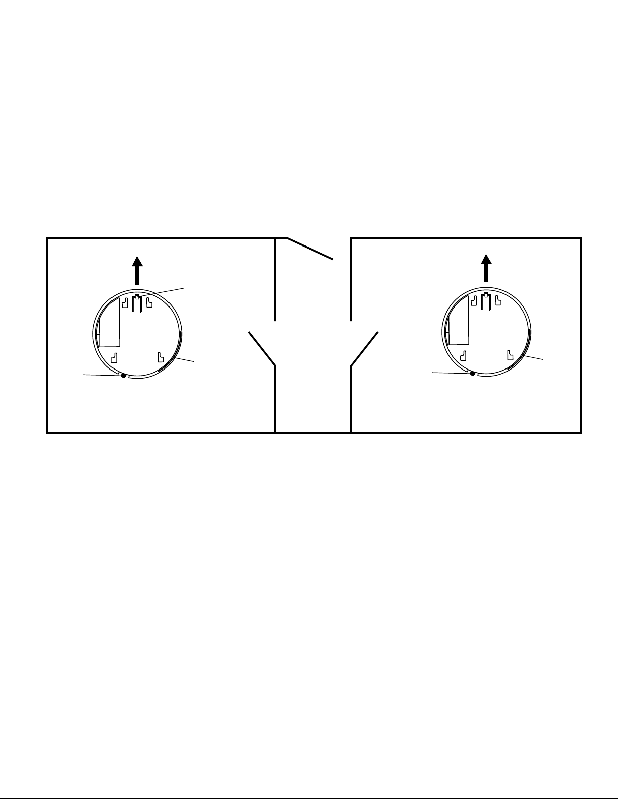
Orientation of RadioLINK bases
It is best practice to align all the RadioLINK bases in the same direction as shown in
the diagram above. This will ensure that all the antennas are in parallel which will
maximise the RF signal strength.
9
Orientate
Latch to
point to
front wall
Orientate all RadioLINK bases in the same direction
Front Wall
Front Wall
RadioLINK Base
LED
Antenna
RadioLINK Base
LED
Antenna
Page 10

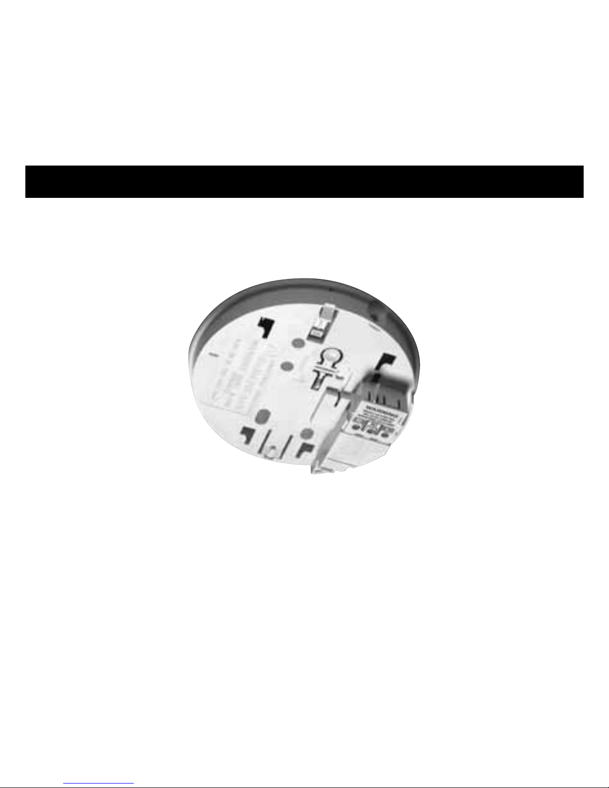
Fixing & Wiring
Select a location complying with the advice in
the Smoke/Heat Alarm instruction leaflet.
Disconnect the AC mains supply from the circuit
that is going to be used.
Remove the cover from the terminal block as
shown here.
Bring the mains wires through the ceiling and
thread them through the hole in the rear of
the base.
If the mains wires are being brought along
the surface, break the knockout and trim to
accommodate the conduit.
10
Page 11

To prevent air draughts affecting smoke or heat
entering the alarm it is important to seal the
area around the hole in the ceiling with foam
or silicon rubber.
Screw the base to the ceiling using a single
screw for now. The second screw should be
inserted at the end of this procedure to secure
the base permanently.
Connect the wiring to the terminal block as
shown here.
L: Live - connect to the house wires coloured
brown, or marked L.
N: Neutral - connect to the house wires coloured
blue, or marked N.
IC: (Hardwire Interconnect- Only used to bridge
a mixed wired and wireless system)
Insert second screw and tighten both screws on the base and replace the terminal cover.
REMOVEABLE
TRUNKING DOOR FOR
11
Page 12

Slide the Alarm head onto the base. Connect the
mains power to the alarm circuit. Check the green
light is on.
Wait 10 seconds and check that the green led on
the Alarm cover is on indicating that mains power
is present.
If the blue light flashes every 10
seconds, remove the alarm and
manually depress the rechargeable
cell “on” switch as shown and refit
the alarm. If there is still a problem
the cells may be depleted so leave
the unit on mains power for 2
hours to charge and test again.
Press and hold the test button. The red led will flash
and the horn will sound.
Repeat this installation procedure for all RadioLINK
bases in the system.
12
Page 13

A maximum of 12 RadioLink bases may be used in any one system. If your system has more
than 12 Alarms please consult your supplier or contact tech support (see back page).
House Coding
When all the RadioLINK bases have been installed and fitted with Alarms, you are
now ready to house code the system.
It is essential to House Code the RadioLINK Bases to ensure they will
not accidently communicate with nearby systems. Failure to house
code the system may also result in a system malfunction.
Press and hold the House Code switch on the
side of any one of the RadioLINK Bases with a
small screwdriver until the blue light illuminates.
Immediately release the switch and the blue light
will flash quickly and then stop. The flashing will
repeat every 5 to 10 seconds thereafter.
Repeat this procedure for all Alarms in the system.
Any additional RadioLINK devices being used in
the system, e.g. Ei450 remote controller must also
be included in the house coding. For house coding
instructions of RadioLINK devices consult their
manuals.
WARNING
BLUE LIGHT
HOUSE CODE SWITCH
13
Page 14

Check that all the devices have been successfully
house coded.
This can be done by counting the amount
of blue flashes on each RadioLINK base. The
number of flashes should correspond to the
number of devices in the system. e.g. if the
system has 4 Alarms and a remote controller
(e.g. Ei450) the blue light on each base will flash
5 times and repeat this pattern every 5 to 10
seconds.
To complete the commissioning, the system
must exit house code mode.
The units will automatically exit house code
after 30 minutes. Once the house coding is
completed the system will not communicate
with any other RadioLINK devices.
The house code procedure can also be
terminated on demand. To do this, press the
house code button on one of the bases. When
the blue light comes on solid release the button.
This unit will then send a signal to all the other
14
Page 15

RadioLINK devices instructing them to exit the
house code mode.
Note: Some RadioLINK devices do not support
the on demand exit house code feature. You may
allow them to automatically exit house code
after the time period or if you wish, you can do
it manually. Consult the individual RadioLINK
device manual for further instructions.
Check the communication by pressing the test/
hush button for up to 20 seconds on each unit
in turn. The red light will flash, the Alarm will
sound and blue light on the RadioLINK Base
sidewall will illuminate continuously for around
3.5 seconds. All other Alarms should sound (this
may take up to 20 seconds).
If all the units are not communicating consult
the “Troubleshooting the RF link” section for
information on how to resolve the problem.
15
BLUE LIGHT
HOUSE CODE SWITCH
Page 16

Factory reset the house code
Sometimes in order to resolve an RF
communication issue, it may be necessary to reset
(factory reset) and house code the system again.
To reset each RadioLINK base insert and hold
a screwdriver into the house code slot on the
base as shown here. The blue light will come on
solid. Hold the screwdriver in position until the
blue light starts to flash (6 seconds approx.) and
then release the screwdriver. When all devices
have been factory reset you can then start a new
house code procedure. To factory reset other
RadioLINK devices consult their manuals.
CAUTION: This is not the same procedure as entering and exiting house code.
16
BLUE LIGHT
HOUSE CODE SWITCH
Page 17

If when checking the RadioLINK interconnection some of the alarms do not respond
to the button test, then:
(i) Ensure you have held the test button down for up to 20 seconds and the blue light
has come on continuously for 3.5 seconds.
(ii) Ensure all bases are orientated the same way with respect to the front wall of the
dwelling (to have the antennas parallel - see below).
4. Troubleshooting the RF link
17
Orientate
Latch to
point to
front wall
Orientate all RadioLINK bases in the same direction
Front Wall
Front Wall
RadioLINK Base
LED
Antenna
RadioLINK Base
LED
Antenna
Page 18

(iii) Extend the flexible antenna from the base housing. To do this, the antenna should
first be removed from its groove in the base of the unit. Remove the breakaway section
in the outer rim and push the antenna in to this groove. For improved signal strength
the antenna can be pushed flat or vertical with respect to the ceiling.
(iv) Re-locate/rotate the units. There are a number of reasons why the radio signals may
not reach all the smoke alarms in your system (see Section on “Limitations of Radio
Communications”). Try rotating the units or re-locating the units (e.g. move them away
from metal surfaces or wiring) as this can significantly improve signal reception.
Rotating and/or relocating the units may move them out of the range of existing
units even though they may have already been House Coded correctly in the system.
It is important therefore to check that all detectors are communicating in their final
installed positions. If units are rotated and/or resited, we recommend that all units are
returned to the factory settings (press and hold the House Code switch on for around
6 seconds until the blue light comes on solidly and then flashes rapidly and stops.
Release the House Code switch). Then House Code all units again in their final positions
as per Section “Installation”. The RadioLINK interconnection should then be checked by
counting the number of flashes and button testing all units.
Note: The RadioLINK Base will only transmit and repeat alarm RF messages as long as
the Smoke Alarm is detecting fire or for 30 minutes whichever is the shorter.
18
Page 19

Check that the green light is on continuously to
indicate that mains power is present and that
the red light flashes every 40 seconds.
Frequent testing of the system is a requirement
to ensure its continued and safe operation.
Guidelines and best practices for testing are
as follows:
1. After the system is installed
2. Once weekly thereafter
3. After prolonged absence from the
dwelling (e.g. after holiday period)
4. After repair or servicing of any of the
systems elements or household
electrical works.
5. Checking & Maintaining the Alarm System
19
Page 20

To test an individual Alarm press and hold the
test button until he horn sounds and the red
light flashes. This will ensure that the sensor,
electronics and sounder are working.
To test the RadioLINK system, press and hold
the test button on one of the Alarms. The blue
light on the side of the Ei168RC base will come
on solid for around 3.5 seconds. Continue to
hold the test button until all the Alarms in the
system are sounding. This will take between
20 to 45 seconds depending on the number
of Alarms in the system, e.g. a system with 12
Alarms will need a 45 second test. Release the
test button when the test is completed. The
local Alarm will stop sounding but you will hear
the other Alarms sounding in the distance and
then die out.
DO NOT TEST WITH FLAME (this can set fire to the Alarm and
damage the house)
We do not recommend testing with smoke or heat as the results can
be misleading unless special apparatus is used.
20
WARNING
Page 21

Battery Back-up Check
Check that the rechargeable lithium battery is
functioning and able to power the Ei168RC. If
the battery is disconnected or depleted the blue
light will flash every 10 seconds
End of Life (EOL) Check
Check the replace unit by date on all Ei168RC
bases and attached Alarms. If the date has been
exceeded then the device should be replaced.
Housekeeping
Wipe the Alarm with a damp cloth. Do not use
any detergents or house cleaning products.
21
Page 22

Vacuum all around the smoke entry openings
in the smoke Alarms to remove any excess dust,
lint, cobwebs, etc.
6. Technical Specification
Supply Voltage 230VAC ~50Hz, 80mA
Battery Back-up 10 year Rechargeable Lithium
RF Frequency 868.499Mhz
Temp Range 0
o
C to 40oC (Cat 3)
Humidity 15% - 95% (Non Condensing)
Receiver Category Cat 2
RF Performance EN 300-220
EMC Performance EN 301-489
RF Power +5dBm (min)
Range >100 meters in free space
Multi-Repeater Range is extended by rebroadcasting
Multi-Path Improves system reliability
Number of RF interconnected Alarms 12 per house code group*
*Note: For applications with greater than 12 Alarms please contact technical
support for guidance.
22
Page 23

7. Guarantee
Ei Electronics guarantees the Model Ei168RC for 5 years from date of purchase against
any defects that are due to faulty materials or workmanship.
This guarantee only applies to normal conditions of use and service and does not
include damage resulting from accident, neglect, misuse, unauthorised dismantling, or
contamination howsoever caused. This guarantee excludes incidental and consequential
damage.
This guarantee does not cover costs associated with the removal and/or installation
of units.
If the product should become defective within the guarantee period, it may be
returned with proof of purchase, carefully packaged, and with the problem clearly
stated to the place of purchase or phone one of these numbers for advice.
UK: 0870 758 4001 ROI: +353 61 471277
We shall at our discretion repair or replace the faulty unit.
8. Limitations of Radio Communications
Ei Electronics radio communication systems are very reliable and are tested to high
standards. However, due to their low transmitting power and limited range (required
by regulatory bodies) there are some limitations to be considered:
(i) Radio equipment, such as the Ei168RC RadioLINK Base, should be tested regularly
23
Page 24

- at least weekly. This is to determine whether there are sources of interference
preventing communication. The radio paths may be disrupted by moving furniture or
renovations, and so regular testing will help identify these and other faults, so that
they can be rectified (see Section 5).
(ii) Receivers may be blocked by radio signals occurring on or near their operating
frequencies, regardless of the House Coding. The Ei168RC RadioLINK Base is in
compliance with the R&TTE Directive (1999/5/EC), and has been proven to provide
reasonable protection against harmful interference in residential installations. This
equipment generates, uses and can radiate radio frequency energy and, if not installed
and used in accordance with the instructions, may cause interference to radio and/or
television reception.
However, there is no guarantee that interference will not occur in a particular
installation. If this device does cause such interference, which can be verified by
turning the RadioLINK device on and off (remove both the mains and turn off backup
power supplies), the user is encouraged to eliminate the interference by one or more
of the following measures:
(i) Re-orientate or re-locate the unit.
(ii) Increase the distance between the Ei168RC and the device being affected.
(iii) Connect the device being affected to a mains outlet on a circuit different from
the one that supplies the Ei168RC.
(iv) Consult the supplier or an experienced radio/television technician.
24
Page 25

9. Getting the RadioLINK Base Serviced
If your RadioLINK Base fails to work after you have carefully read all the instructions
and checked that the unit has been installed correctly contact Customer Assistance at
the nearest address given at the end of this leaflet.
If it needs to be returned for repair or
replacement, lightly press the “off” switch to
disconnect the rechargeable cells and put both
the Alarm and the Ei168RC RadioLINK Base in a
padded box and send it to “Customer Assistance
and Information” at the nearest address given on
the unit or in this leaflet.
State the nature of the fault, where the RadioLINK Base and Alarm were purchased and
the date of purchase. Do not snap the Smoke/Heat Alarm on to the RadioLINK Base as
this connects the battery and the unit may beep or Alarm in the post.
RECHARGEABLE
CELL "ON" SWITCH
25
Page 26

26
The crossed out wheelie bin symbol that is on your
product indicates that this product should not be disposed
of via the normal household waste stream. Proper
disposal will prevent possible harm to the environment or
to human health. When disposing of this product please
separate it from other waste streams to ensure that it can
be recycled in an environmentally sound manner. For
more details on collection and proper disposal, please
contact your local government office or the retailer where
you purchased this product.
Block E1
0889
Hereby, Ei Electronics declares that this Ei168RC RadioLink Alarm Base,
is in compliance with the essential requirements and other relevant
provisions of Directive 1999/5/EC. The Declaration of Conformity may be
consulted at www.eielectronics.com/compliance
Page 27

27
Page 28

Aico Ltd
Mile End Business Park,
Maesbury Road, Oswestry,
Shropshire SY10 8NN, U.K.
Telephone: 0870 7584000
www.aico.co.uk
Ei Electronics
Shannon Industrial Estate,
Shannon, Co. Clare, Ireland.
Telephone: +353 (0)61 471277
www.eielectronics.com
P/N B17688 Rev 3© Ei Electronics 2013
 Loading...