

RadioLAN Campus BridgeLINK User Manual

Wireless Local Area Network
Campus BridgeLINK™ User Guide
890-007 Rev. A 01/28/99 © 1999 RadioLAN. All rights Reserved

Notices
FCC
This equipment has been tested and found to comply with the limits for a Class A digital device, pursuant to Part
15 of the FCC rules. These limits are designed to provide reasonable protection against harmful interference in a
residential installation. This equipment generates, uses, and can radiate radio frequency energy and, if not
installed and used in accordance with the instructions, may cause harmful interference to radio communications.
However, there is no guarantee that interference will not occur in a particular installation. If this equipment does
cause harmful interference to radio or television reception, which can be determined by turning the equipment off
and on, the user is encouraged to try to correct the interference by one of the following measures:
• Reorient or relocate the receiving antenna.
• Increase the separation between the equipment and receiver.
• Connect the equipment into an outlet on a circuit different from that to which the receiver is connected.
• Consult the dealer or an experienced radio/TV technician for help.
FCCID: MCIPUNIIT
FCC Rule Part(s): 15
Frequency (MHz): 5775, 5200, 5300
Equipment Class Low Power Communication Device Transmitter
890-007 Rev. A 01/28/99 Page ii © 1999 RadioLAN.

Remarks:
UNII WLAN and Class A PCMCIA Card
Maximum Output Power: 50 mW
Notes:
This device has shown compliance with new rules adopted under Docket 87-389 and is not affected by
Section 15.37, transition rule.
Each radio is marked with its operating frequency.
FCC regulations require that this device be professionally installed by a person knowledgeable in electronics and
trained in the correct installation of this device.
UL safety listing requires that the installation conform to the National Electrical Code sections 810 and 820.
All interface cables must be shielded.
This device complies with Part 15 of FCC rules. Operation is subject to the following two conditions: 1) this device
may not cause harmful interference, and 2) this device must accept any interference received, including
interference that may cause undesired operation.
890-007 Rev. A 01/28/99 Page iii © 1999 RadioLAN.

Disclaimer
The instructions in this document have been carefully checked for accuracy and are presumed to be reliable.
RadioLAN and its writers assume no responsibility for inaccuracies and reserve the right to modify and revise this
document without notice.
It is always our goal at RadioLAN to supply accurate and reliable documentation. If you discover a discrepancy in
this document, please e-mail your comments or suggested corrections to marketing@radiolan.com.
No part of this publication may be placed in a retrieval system, transmitted, or reproduced in any way, including,
but not limited to, photograph, photocopy, computer disk or other record, without prior agreement and written
permission from:
RadioLAN
455 De Guigne Drive
Sunnyvale, CA 94086
© 1999 RadioLAN, Sunnyvale, CA, USA. All rights reserved.
890-007 Rev. A 01/28/99 Page iv © 1999 RadioLAN.

Trademark Disclosures
RadioLAN has made every effort to provide disclosures when using trademarks owned by other companies.
Trademarked designations appear throughout this publication. The publisher states that it is using the
designations only for editorial purposes, and to the benefit of the trademark owner with no intent to infringe upon
that trademark. The following trademarks are found in this manual:
Microsoft™, Windows for Workgroups™, Windows 95™, Microsoft Internet Explorer™, and Windows NT™ are trademarks of
Microsoft Corporation.
Netscape™ is a registered trademark of The Netscape Corporation;
Novell™ and NetWare™ are trademarks of Novell, Inc.
Xerox™ is a trademark of Xerox Corporation.
IBM™ is a trademark of International Business Machines.
10BaseRadio™ and RadioLAN/10™ are trademarks of Radio/LAN.
Java™ is a trademark of Sun Microsystems, Inc.
Manual Conventions
The following text formats are used throughout this manual:
References to other locations in the manual or to other manuals provided by RadioLAN are italicized.
Narrow Bold Letters describe buttons and fields on the screen.
SMALL CAPITAL LETTERS describe Screen Names or Screen Tab Names.
Bold and Italicized Letters indicate important information.
890-007 Rev. A 01/28/99 Page v © 1999 RadioLAN.

Table of Contents
Notices...................................................................................................................................................................ii
FCC........................................................................................................................................................................ii
Disclaimer.............................................................................................................................................................. iv
Trademark Disclosures ............................................................................................................................................ v
Manual Conventions................................................................................................................................................ v
Introduction.........................................................................................................................................................1
The Campus BridgeLINK™ System ..........................................................................................................................3
The Directional Antenna ...........................................................................................................................................8
A Typical Campus BridgeLINK™ Application...........................................................................................................10
Determining the Distance between Buildings...........................................................................................................11
Initial IP Address Setup.........................................................................................................................................12
Installing the CPU............................................................................................................................................15
Tools You Will Need ..............................................................................................................................................15
Locating the CPU ..................................................................................................................................................16
Mounting the CPU .................................................................................................................................................17
Grounding Considerations ......................................................................................................................................20
Installing the Antenna.....................................................................................................................................21
890-007 Rev. A 01/28/99 Page vi © 1999 RadioLAN.

A Brief Word About Safety......................................................................................................................................21
Choosing the Best Mounting Height........................................................................................................................22
Sighting Each Campus BridgeLINK™ Antenna........................................................................................................23
Apply Power to the CPU.........................................................................................................................................25
Adding Security to the Wireless Network.................................................................................................................26
Local Management................................................................................................................................................26
Dual Remote Management: HTML and SNMP .........................................................................................................26
Using the Campus BridgeLINK™ Manager...............................................................................................28
The CPU Web Site ................................................................................................................................................28
Browsing the Network for the CPU ..........................................................................................................................29
Logging onto Campus BridgeLINK™ Manager.........................................................................................................29
Campus BridgeLINK™ Manager Site Layout...........................................................................................................31
Aiming the Directional Antennas.............................................................................................................................33
Setting Up Security Features ..................................................................................................................................35
Setting Up SNMP Capabilities................................................................................................................................36
Setting the CPU’s Mode of Operation ......................................................................................................................47
Securing the CPU with Data Encryption ..................................................................................................................48
Bridging the Link and 10BaseT Networks................................................................................................................49
Managing Packet Flow Through the CPU................................................................................................................57
Interrogating the System for Performance Information ..............................................................................................67
Upgrading System Software...................................................................................................................................74
Saving or Rejecting Configuration Setting Changes .................................................................................................77
Resetting the CPU.................................................................................................................................................79
890-007 Rev. A 01/28/99 Page vii © 1999 RadioLAN.

Recording Important System Information.................................................................................................80
Viewing the System Log .........................................................................................................................................83
Managing the CPU Locally............................................................................................................................84
CPU Local Management........................................................................................................................................86
Hot Keys ...............................................................................................................................................................86
Logging onto the CPU Configuration Screen............................................................................................................87
Using the Main Menu.............................................................................................................................................89
Working with the System Configuration Menu ..........................................................................................................91
Configuration Manager Menu Items ........................................................................................................................95
Troubleshooting.............................................................................................................................................108
Glossary............................................................................................................................................................110
Appendix A: Indicators, Switches, and Connectors.............................................................................113
Indicators............................................................................................................................................................ 113
MDI/MDI-X Switch ............................................................................................................................................... 114
I/O Connectors.................................................................................................................................................... 115
Serial Port Connector...................................................................................................................................116
Appendix B: Technical Specifications.....................................................................................................117
Network Protocol................................................................................................................................................. 117
Standards Support............................................................................................................................................... 117
890-007 Rev. A 01/28/99 Page viii © 1999 RadioLAN.

Electrical Specifications........................................................................................................................................ 117
Physical Specifications......................................................................................................................................... 118
Environmental Specifications................................................................................................................................ 118
Electromagnetic Emissions .................................................................................................................................. 119
Safety Agency Approvals ..................................................................................................................................... 119
Getting Technical Support...........................................................................................................................120
890-007 Rev. A 01/28/99 Page ix © 1999 RadioLAN.

Notes
890-007 Rev. A 01/28/99 Page x © 1999 RadioLAN.
Introduction
Historically, connecting two buildings to allow networking
between two local area networks required the expense
and effort related to running a cable from one building to
another. This may have involved installing an aerial cable
or digging a trench and installing conduit and wiring
between the two buildings, which is time-consuming,
labor-intensive, and costly.
After installation, cable degradation, due to moisture,
corrosion, or alterations in landscaping, can compromise
the network connection between the two buildings.
Repairing and replacing cable runs is also costly, timeconsuming, and labor-intensive.
RadioLAN overcomes these difficult installation issues
with its Campus BridgeLINK™ product line. This exciting
new technology easily connects two buildings, using radio
frequency technology. Because this technology uses
radio frequency to make the connection between the
buildings, cable runs, conduit, trenching, and labor
involved with these activities are no longer required.
890-007 Rev. A 01/28/99 Page 1 © 1999 RadioLAN, Inc.
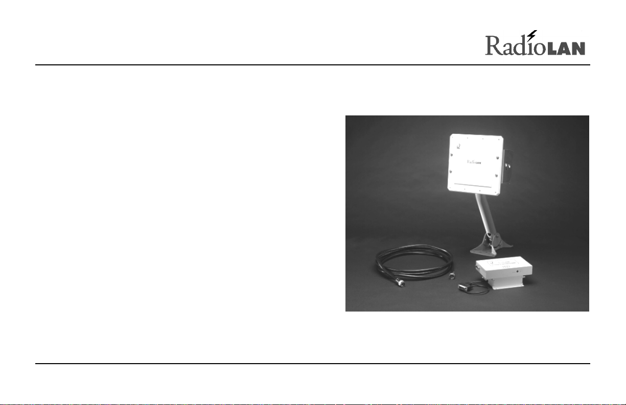
Figure 1: Campus BridgeLINK™ Products

RadioLAN allows you to connect two buildings, which are up to one mile apart, using a Campus BridgeLINK™
Processor Unit (CPU), a Companion Radio Module (CRM), and an 8.86” square directional antenna for each
building link. When using the Campus BridgeLINK™ application, you need only install the components at each
building, aim the antennas toward one another, and power the system on. The only requirements for each
building location are Campus BridgeLINK™ system components and access to network cabling and power.
The directional antenna and its cabling is weatherproof, small-profile, and sturdy. Because the directional antenna
allows for a 19° angle of operation, aiming the antennas so they point toward one another is nearly effortless.
Connecting two networks in two locations using the old-fashioned, hard-wired method could take days,
considering the labor intensive effort needed. When using Campus BridgeLINK, the task is simplified. The task of
connecting two networks is reduced to mere hours, without the back-breaking labor related to trenching, laying
conduit and then cleaning up the landscaping mess afterward.
In this section, we will introduce you to the concepts of Campus BridgeLINK™ communication, using a RadioLAN
Wireless Campus BridgeLINK™ system. Here, you will become familiar with the CPU, the CRM, the directional
antenna, and the signal analysis tools.
890-007 Rev. A 01/28/99 Page 2 © 1999 RadioLAN, Inc.
The Campus BridgeLINK™ System
Local Port
10BaseT Port
The Campus BridgeLINK system includes the Campus
BridgeLINK™ Processor Unit (CPU) with a mounting bracket,
a Companion Radio Module (CRM), and a directional antenna.
Also included is the power transformer that you can plug into a
non-switched electric outlet. You can install these items in
plain view, hidden away in a closet, or above ceiling tile.
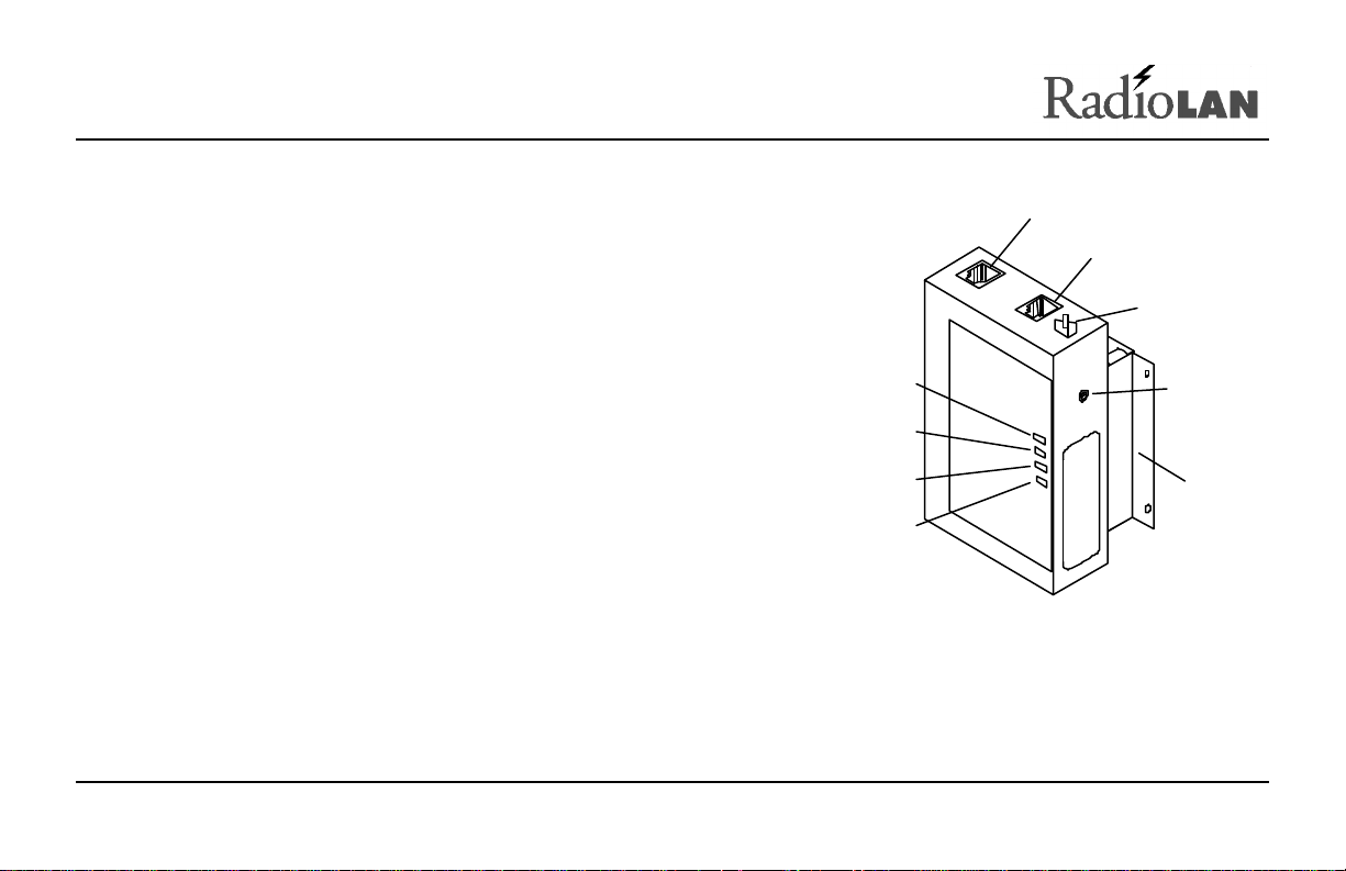
Campus BridgeLINK™ Processor Unit (CPU)
The CPU features a number of LED indicators, switches, and
jacks that allows you to connect the module to external
devices and help you see the CPU status.
LED Indicators
The face of the CPU features four LED indicators:
• The green Power LED illuminates when power is applied
to the CPU. As long as the CPU is powered, this LED is
normally illuminated.
890-007 Rev. A 01/28/99 Page 3 © 1999 RadioLAN, Inc.
Status LEDs:
Fault
Status 2
Status 1
Power
Figure 2: CPU (Campus BridgeLINK™
Processor Unit)
MDI/MDI-X
Selector
Power
Jack
Radio
Mounting
Bracket

• The amber Fault LED illuminates for several seconds during the power-on diagnostic sequence. When the
CPU is operating, this LED is normally extinguished.
• The green Status 1 LED illuminates when the CPU detects the presence of the distant CPU. When the CPU
is operating, this LED normally illuminates when the near and far CPUs are active.
• The green Status 2 LED illuminates when the CPU detects the presence of data passing through the wireless
link. During normal CPU operation, this LED flickers when near and far CPUs are active.
One end of the CPU features a button and two ports:
• MDI/MDI-X selector button
• 10BaseT port
• Local port
MDI/MDI-X Switch
The MDI/MDI-X selector button switches the jack’s pin assignment of transmit and receive data wire pairs for the
10BaseT port.
Use MDI-X configuration when the remote end of the wires is connected to a network station. For example, use
this setting when connecting the CPU to a 10BaseT Network Interface Card or to an MDI port with a 10BaseT
concentrator.
Set the switch for MDI configuration when the remote end of the wire is connected to a 10BaseT concentrator or a
hub.
890-007 Rev. A 01/28/99 Page 4 © 1999 RadioLAN, Inc.

10BaseT Port Jack
Next to the MDI/MDI-X selector button you will find the 10BaseT port. The 10BaseT port interfaces the CPU to its
local area network. The 10BaseT port is RJ45-compatible, which allows an eight-wire connection to a network
hub or other hard-wired external device.
10BaseT LED Indicators
On the upper left and right corners of the 10BaseT port are green LEDs which indicate transmit and receive status
from the network.
When the CAR LED illuminates, this indicates that the Ethernet carrier is active.
When the ACT LED illuminates, this indicates Ethernet activity on the network. This LED flickers during normal
operation.
Local Port Jack
Located on the opposite end from the selector button, on the same face of the CPU, is the local port jack. The
local port is compatible with RJ11 connectors and allows connection to a local terminal. When you need a local
terminal connection, use the local terminal to configure the CPU.
890-007 Rev. A 01/28/99 Page 5 © 1999 RadioLAN, Inc.
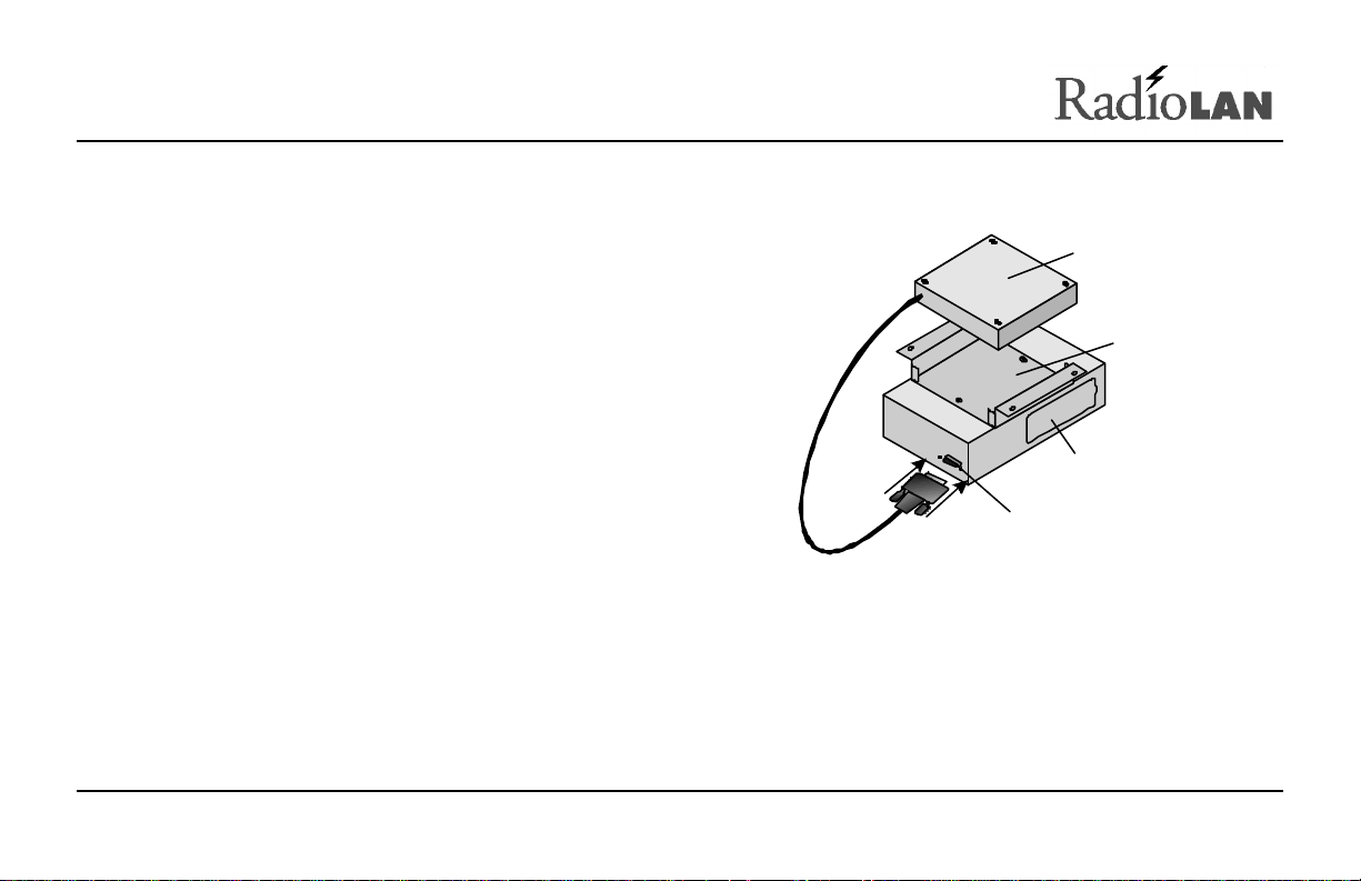
CRM Port
CPU
CRM
CRM Port
Mounting
At the opposite end of the CPU, there is a female 15-pin
D connector. The connector allows you to connect the
CRM to the CPU, using the cable that is attached to the
Radio Unit.
Bracket
Mounting Bracket
The mounting bracket is specially shaped so that it
allows the CRM to slide into the mounting bracket
before securing the CPU to a flat surface.
Figure 3: CRM (Companion Radio Module) Port
890-007 Rev. A 01/28/99 Page 6 © 1999 RadioLAN, Inc.
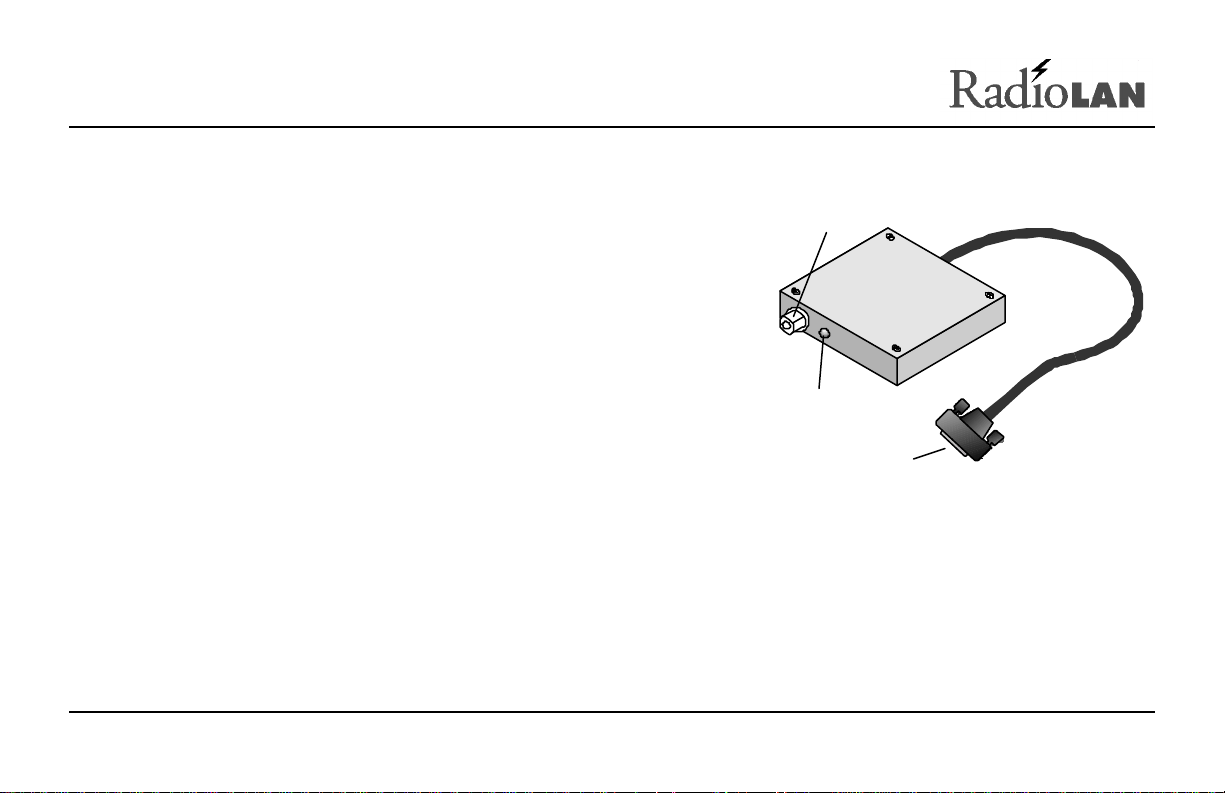
The Companion Radio Module (CRM)
Directional Antenna
Connector
The CRM interfaces the CPU with the directional antenna. The
CRM is small, durable, and designed to insert easily into the
Connector (Type N)
mounting bracket that is attached to the CPU.
On one end of the CRM, there is a Type N connector and an LED
indicator. The Type N connector attaches the CRM to the
directional antenna.
The LED illuminates amber when the CRM is transmitting data. It
illuminates green when the CRM is receiving data.
Activity
LED
CPU
Figure 4: CRM (Companion
Radio Module)
890-007 Rev. A 01/28/99 Page 7 © 1999 RadioLAN, Inc.
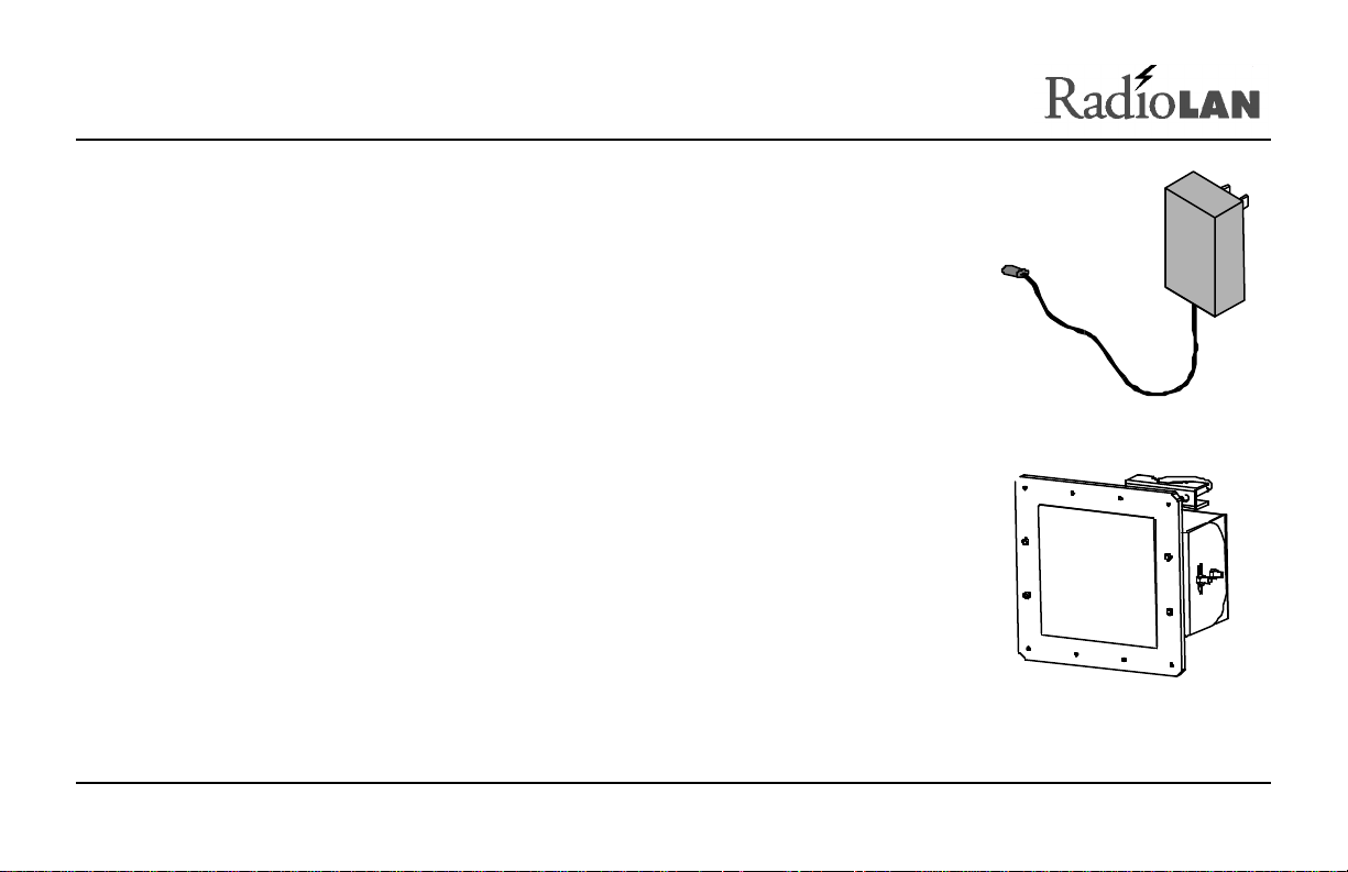
Power Transformer
The power transformer provides an easy connection to electrical outlets. One end of
the transformer has a power cable with a connector that is compatible with the
CPU’s power jack. The other end plugs into an electrical outlet. RadioLAN
recommends using a non-switched electrical outlet for connection to the CPU.
Figure 5: Power
Transformer
The Directional Antenna
The directional antenna assembly includes the directional antenna and a mounting
clamp. The directional antenna is a 18dbi-gain, small-profile directional antenna. It is
8.86 inches square, and mounted on a pivoting base.
Figure 6: Directional
Antenna
890-007 Rev. A 01/28/99 Page 8 © 1999 RadioLAN, Inc.
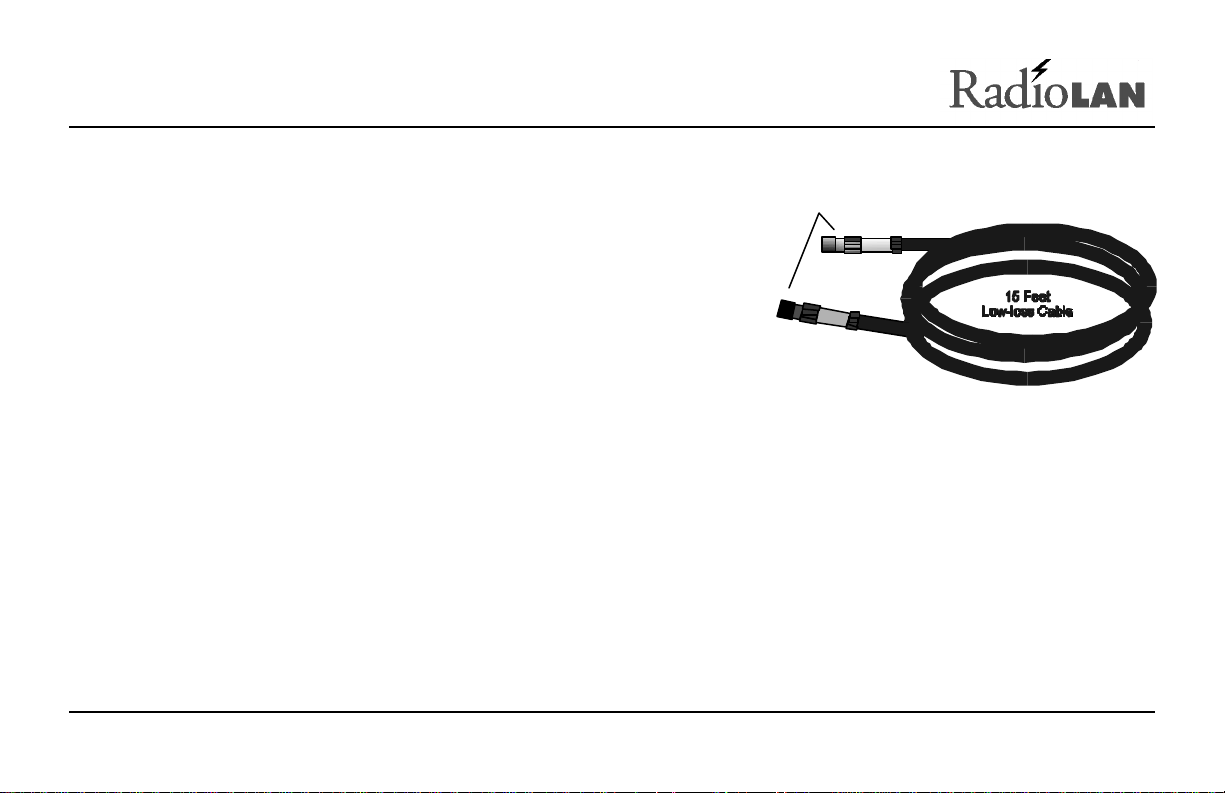
Antenna Cable
Type N Connectors
The antenna cable provided is a 15-foot, low-loss cable. It is made
of fire retardant material, and is UV stabilized. Cold-shrink tubing is
supplied to cover the antenna end connector after connection to the
cable. See the installation instructions packaged with the shrink
tubing for installation directions.
Figure 7: Low-Loss RF Cable
890-007 Rev. A 01/28/99 Page 9 © 1999 RadioLAN, Inc.
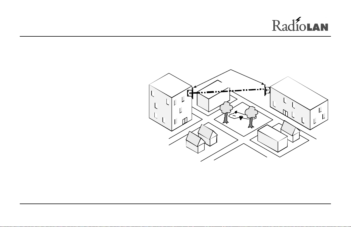
A Typical Campus BridgeLINK™ Application
8.8“ Directional Antenna
Figure 8 shows a typical Campus
BridgeLINK application in which two
buildings, with local area networks in
each, are located up to one mile away
from one another. Notice that there are
no solid obstructions between the two
buildings and that each building
antenna points toward the other.
Because the system uses radio
frequency to establish the connection
between the two buildings, it is
important to avoid blocking the radio
link with any objects, such as a trees,
buildings, walls, or items that are
attached to the building walls, such as stairwells,
fire escapes, or other antenna equipment.
890-007 Rev. A 01/28/99 Page 10 © 1999 RadioLAN, Inc.
Figure 8: A Typical Campus BridgeLINK™
Up to 1 Mile Apart
Application
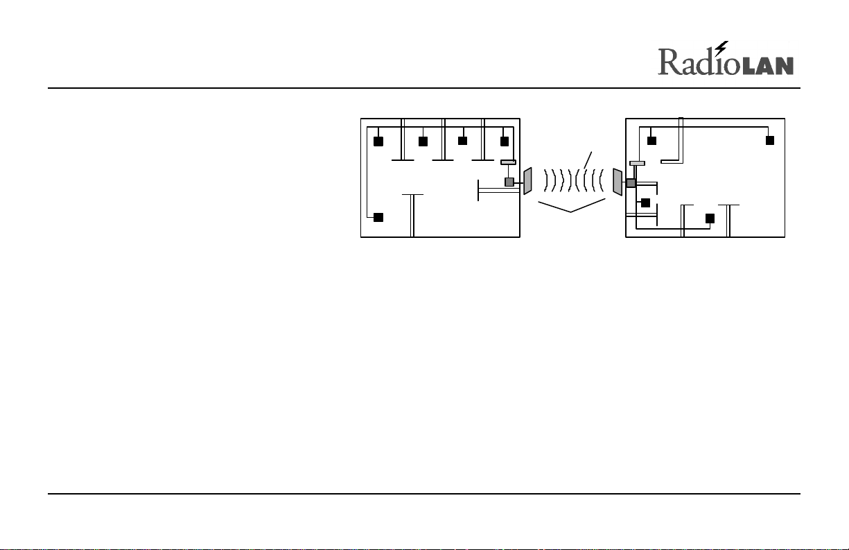
Figure 9 illustrates the networks inside
Campus BridgeLINK
Hub
CPU
each building. Notice that the CPU is
attached directly to a hub, which
connects network nodes together.
Hub
CPU
(Up to 1 mile apart)
Building 1 Building 2
Wireless
Link
Modules
Figure 9: Linking Networks in Two Locations
Determining the Distance between Buildings
It is important to verify that you do not exceed the distance capabilities of Campus BridgeLINK. If you are unsure
of the distance between the two points, you can use a measuring device, such as optical devices found in some
binoculars, or a tape measure. You can also see the architect’s site plan or contact a local surveying service for
assistance.
890-007 Rev. A 01/28/99 Page 11 © 1999 RadioLAN, Inc.
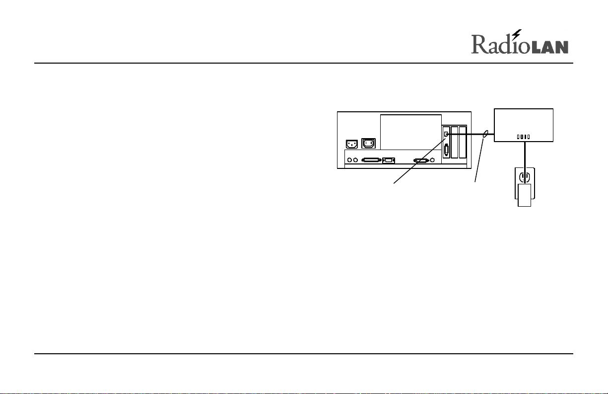
Initial IP Address Setup
Before you can use the TCP/IP management services of
CPU
a CPU, it must contain a valid network IP Address. There
are three ways to assign an IP Address to the CPU:
• Connection between the CPU and a PC on the same
local LAN segment
• A VT-100 terminal connection to the CPU Local Port
This section describes in detail each method for assigning
10BaseT Network
Interface Card
Figure 10: Quick Configuration
10BaseT Ethernet
or Crossover Cable
Power
Adapter
the CPU an IP Address.
890-007 Rev. A 01/28/99 Page 12 © 1999 RadioLAN, Inc.

Temporarily Connect the CPU
To use the IP ASSIGN Utility, you must first obtain a PC with a 10BaseT Network Interface Card that has its own
IP Address. The PC must not be running a DHCP Server while performing this procedure.
1. Determine the method that you are using to assign the IP Address:
Using a PC with a 10BaseT Network Interface Card: If you installed the IP ASSIGN Utility in a PC with a
10BaseT Network Interface Card, connect an RJ45, 10BaseT cable between the CPU and the jack on the
PC’s Network Interface Card.
Using the CPU Local Port: If you are using the local port, connect the serial port from a VT-100 terminal to
the CPU local port.
2. Connect the Radio Unit to the CPU.
3. Connect the CPU’s power adapter to the power jack on the CPU.
4. Plug the CPU’s power adapter into a 115VAC electrical outlet.
The CPU’s Power LED illuminates.
If you are using a PC with a network interface card, see Using the IP ASSIGN Utility to Assign the CPU’s IP
Address on page 14. If you are using the CPU local port, see Managing the CPU Locally on page 86.
890-007 Rev. A 01/28/99 Page 13 © 1999 RadioLAN, Inc.
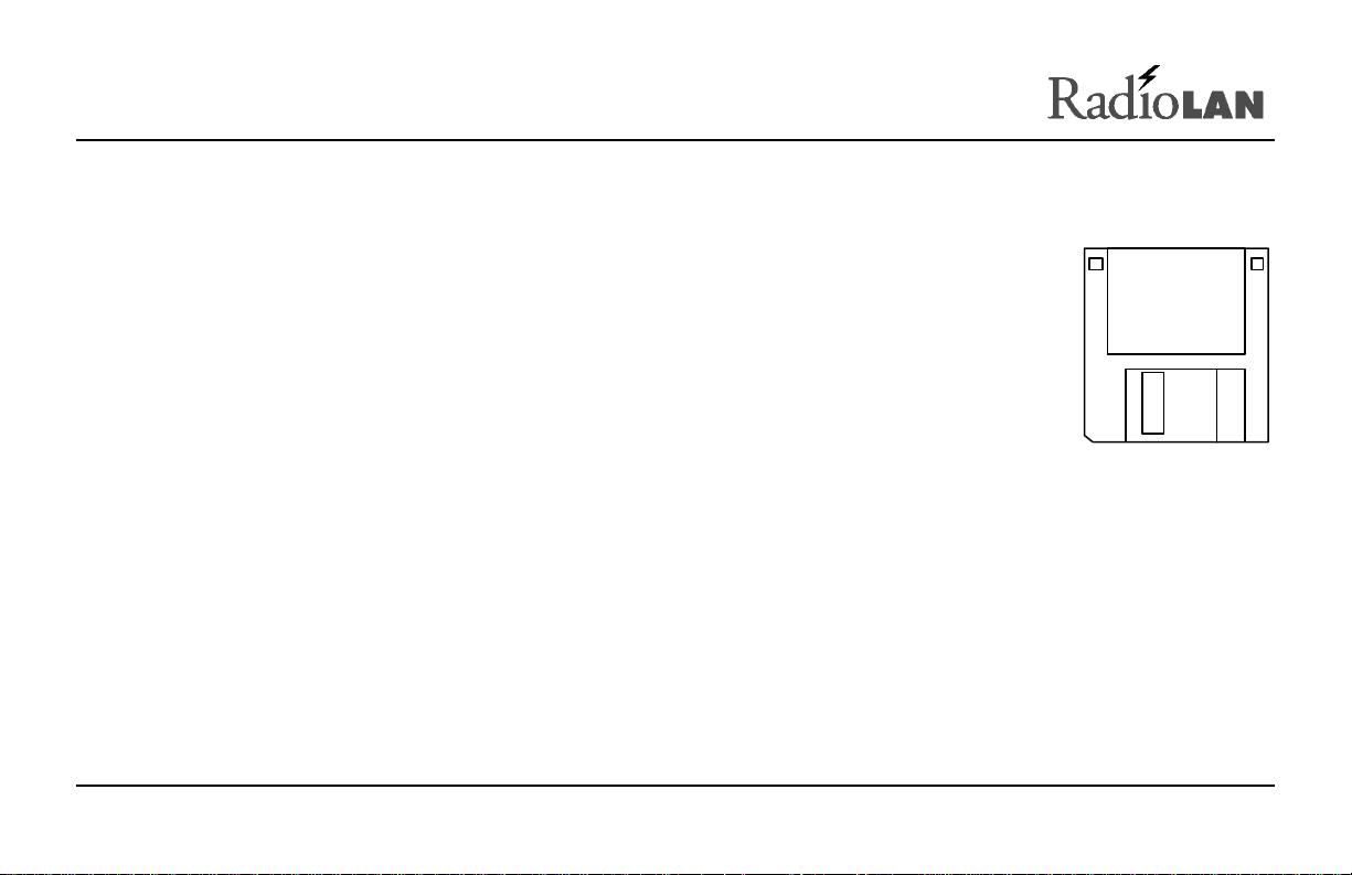
Using the IP ASSIGN Utility to Assign the CPU’s IP Address
RadioLAN provides the IP ASSIGN Utility diskette with your package. The utility allows you
to assign an IP Address to the CPU quickly.
To install the IP ASSIGN Utility and assign an IP Address to the CPU, follow these steps
from a PC connected to the CPU:
1. Insert the IP ASSIGN Utility diskette into drive A.
2. Using the Windows RUN command, type A: IP ASSIGN and click OK.
The utility starts and begins searching the local LAN segment for any CPUs that are not
configured with an agent IP Address.
The utility returns a page listing of the Media Access Control (MAC) Addresses for all
non-configured CPUs on the LAN segment.
Figure 11:
Configuration
Disk
3. Highlight the MAC Address for the CPU that you want to configure.
4. Enter the desired temporary IP Address for the CPU. Later, you can permanently set it using the IP
PARAMETERS page.
The utility checks the IP Address to verify its validity. If the newly entered IP Address is valid, the utility
assigns it to the CPU and prompts you to configure the CPU using your network browser.
5. Choose Yes to launch your default network browser, and press Enter.
The utility displays the login page for the CPU configuration program.
890-007 Rev. A 01/28/99 Page 14 © 1999 RadioLAN, Inc.

Installing the CPU
When installing a CPU you must mount it onto a wall or a ceiling. You must locate the CPU at a distance from the
antenna that is no farther than the cable will allow. The cable length is a maximum of 15 feet; this means you
must consider all bends in the cable when determining your distance.
You must also locate the CPU in an area from which it has access to local network cabling and electricity. Before
selecting an electrical outlet for use in powering the CPU, verify that the electrical outlet is non-switched (for
example, it is not attached to a wall switch). You should also consider placing the CPU in a location where it is out
of reach of the general public.
FCC regulations require that this device be professionally installed by a person knowledgeable in
electronics and trained in the correct installation of this device.
All interface cables must be shielded.
Tools You Will Need
To install the CPU, you will need the following tools: drill, drill bit, screwdriver, screws, pencil, measuring tape.
890-007 Rev. A 01/28/99 Page 15 © 1999 RadioLAN, Inc.
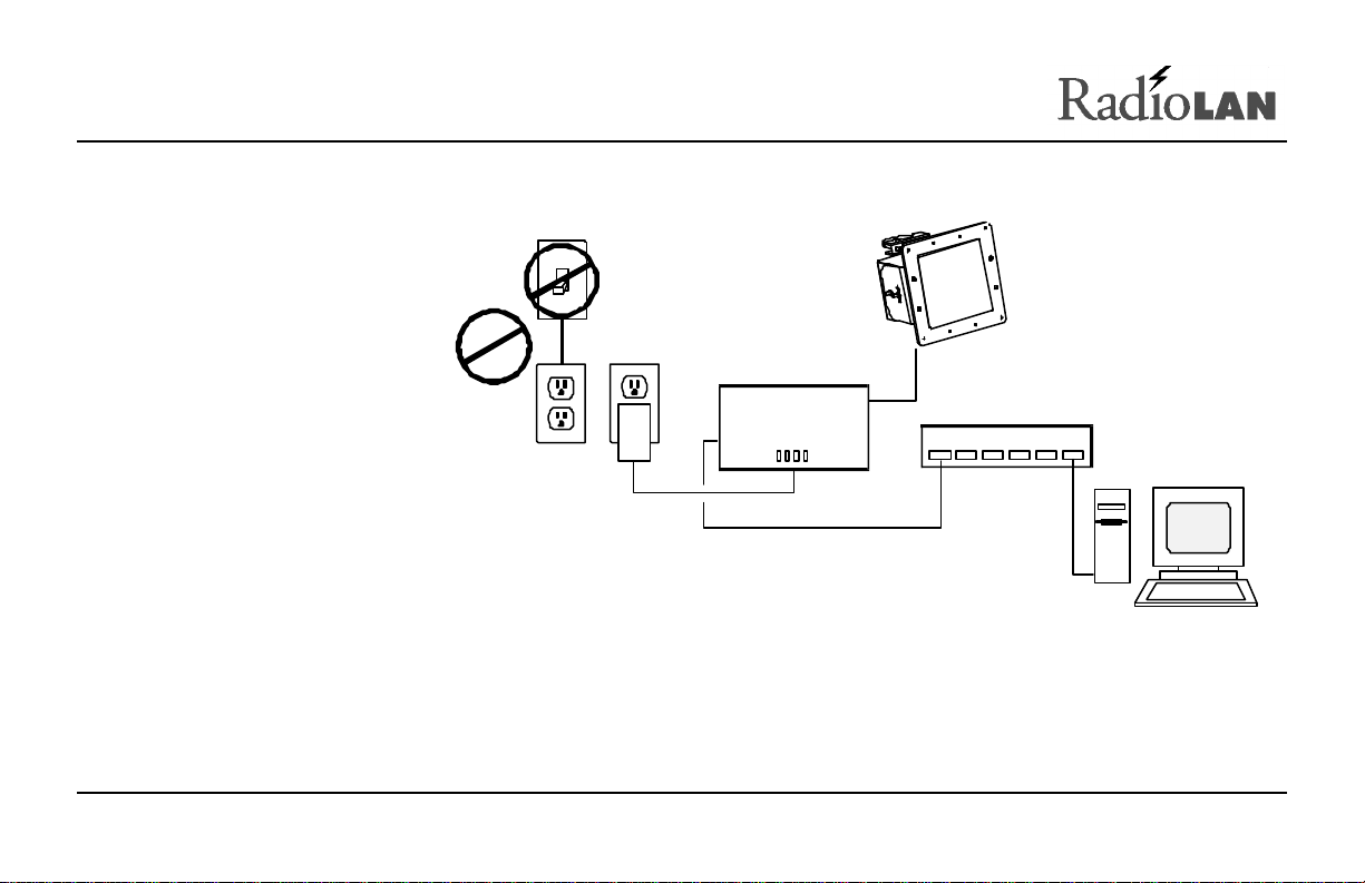
Locating the CPU
Wired Network Server
After verifying that the
CPU is located near a
power source and network
cabling, and is within the
15-foot cable distance
constraint of the antenna,
you must install the CPU
Switched
Outlet
securely to the mounting
surface (for example, a
wall or ceiling).
Non-switched
Outlet
890-007 Rev. A 01/28/99 Page 16 © 1999 RadioLAN, Inc.
Directional Antenna
Campus
BridgeLINK
Module
10BaseT HUB
1 2 3 4 5 6
Figure 12: Locating the CPU Closely to
Network, Power, and the Antenna
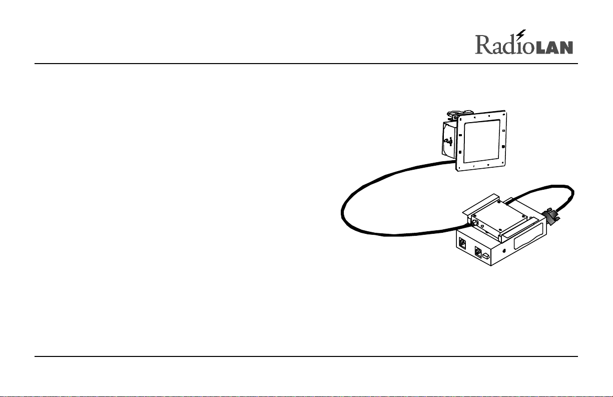
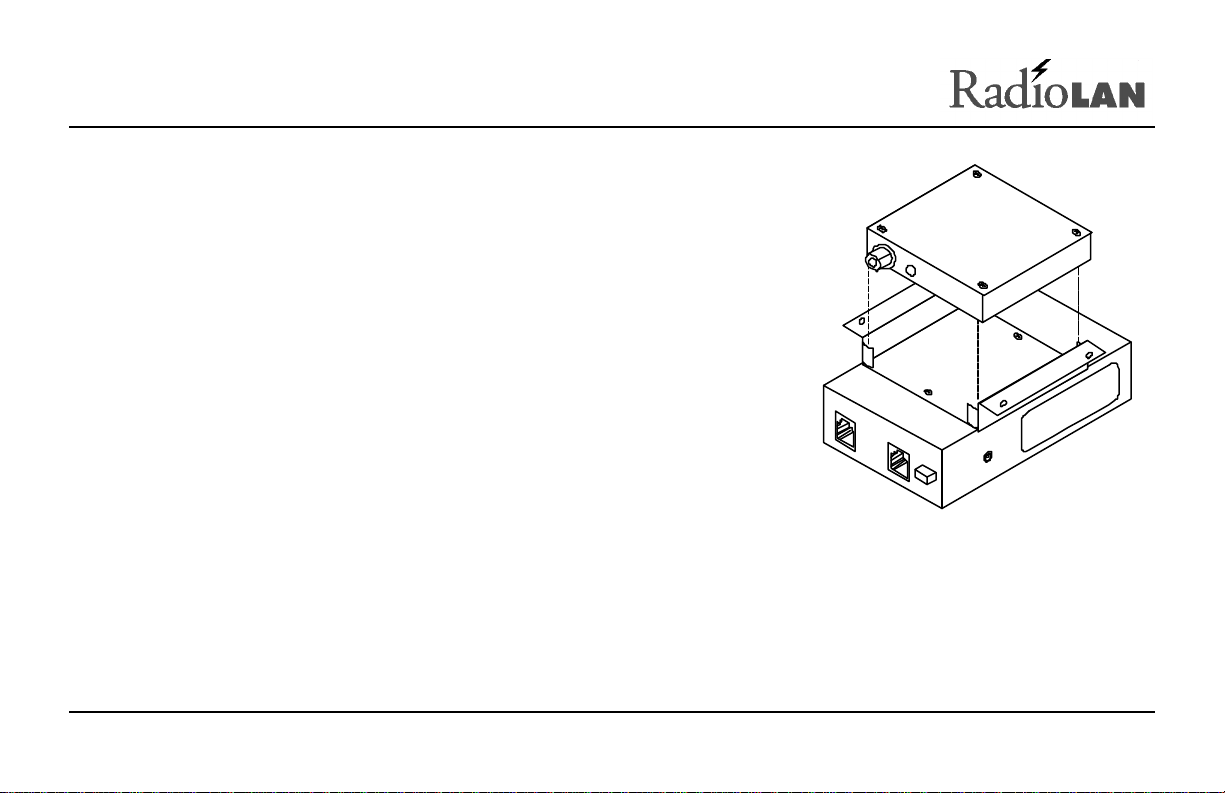
Mounting the CPU
When mounting the CPU, you must follow these steps.
Before mounting the CPU to the mounting surface,
connect the connector at the end of the CRM’s cable to
the 15 pin D connector on the CPU (see Figure 13).
Route the antenna cable from the directional antenna to
the CRM, and slip the cold-shrink tubing over the end of
the cable before connecting the cable to the antenna.
Connect the cable to the CRM, using a clockwise rotation.
Tighten the antenna connector so that it is snug but does
not strip the threads of the connector on the CRM.
Complete the shrink tubing installation by following the
instructions provided with the tubing.
Figure 13: Connecting the Antenna Cable to
the CRM
890-007 Rev. A 01/28/99 Page 17 © 1999 RadioLAN, Inc.
Orient the CRM so that its cable does not cross over the mounting
brackets and then insert the CRM into the mounting bracket so that it is
flush with the rim of the bracket (see Figure 14).
Orient the CPU on the mounting surface in the location where you would
like it to be attached.
Figure 14: Inserting the CRM into the Bracket
890-007 Rev. A 01/28/99 Page 18 © 1999 RadioLAN, Inc.
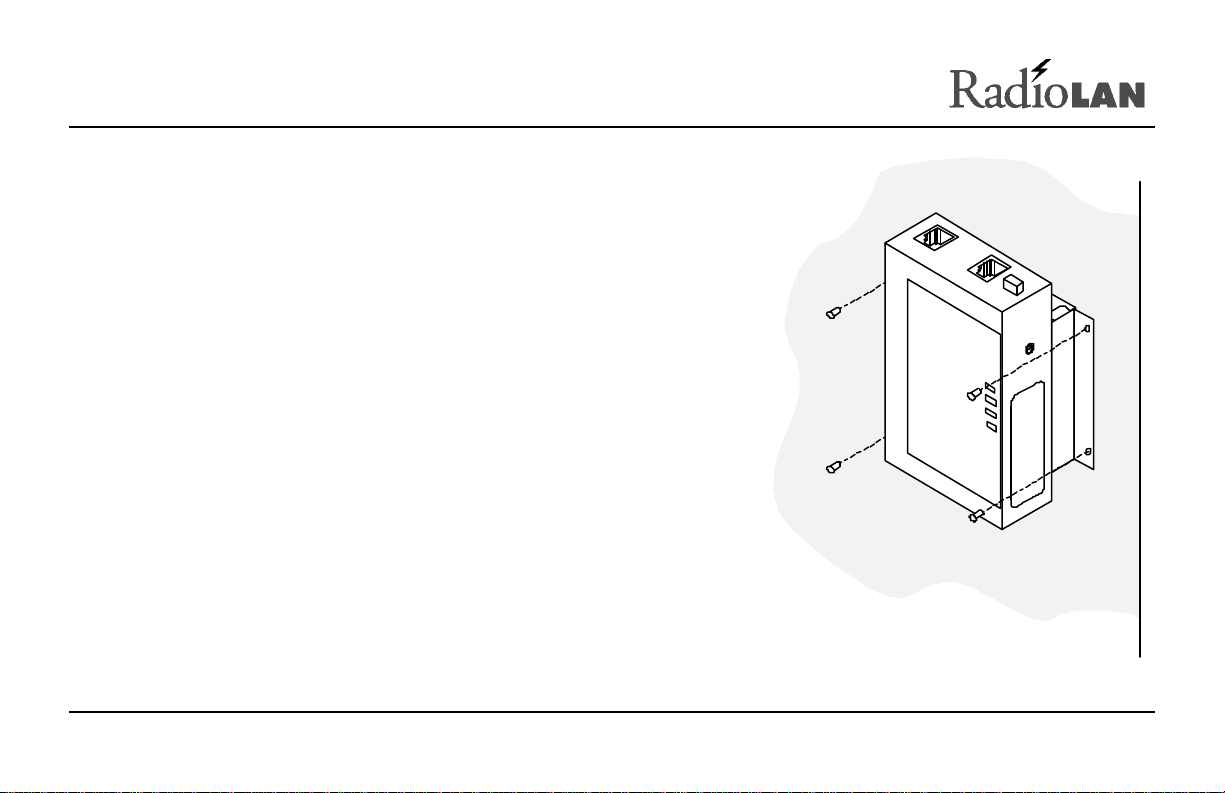
Use a pencil to mark the brackets screw hole locations onto the
surface upon which you will mount the CPU.
At the location’s screw holes, install any necessary anchoring
devices. This is especially recommended when installing the CPU
onto a sheet-rock or gypsum surface.
Hold the CPU up to the mounting surface (see Figure 15),
orienting the screw holes with the mounting anchors, then drive
screws securely into the surface. Tighten down the screws.
Connecting the Network
When connecting the CPU to the hardware network hub or to a
PC, you must use a RJ45-compatible, dual modular cable. The
cable is an eight-wire, twisted-pair cable and must not exceed the
distance limitations provided by the IEEE 802.3 standard. After
routing the cable to the network, insert the modular connector into
the port on the CPU.
Figure 15: Marking Screw Locations
890-007 Rev. A 01/28/99 Page 19 © 1999 RadioLAN, Inc.
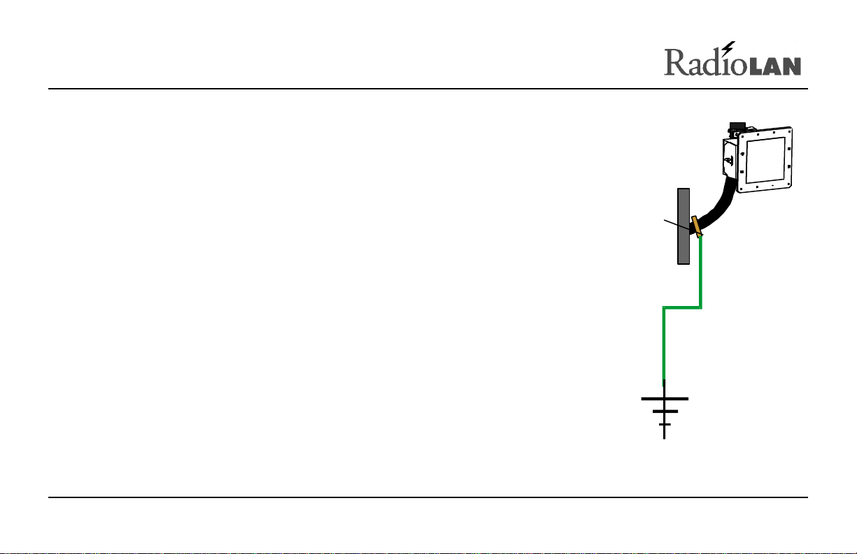
Grounding Considerations
Ground
RadioLAN recommends that you properly ground the directional antenna as
described in mounting hardware installation instructions and required by
your local ordinances.
RadioLAN recommends that you connect the antenna assembly to a ground
rod driven a minimum of 10 feet into the soil. For proper grounding of the
antenna and cable follow Section 810 of the National Electrical Code. Use
UL-listed ground clamps and lugs.
Figure 16: Acceptable Ground Source
890-007 Rev. A 01/28/99 Page 20 © 1999 RadioLAN, Inc.
Dish Mounting
Hardware
Clamp
Approved
Ground
 Loading...