

Page 1

™
PCMx
Pipeline Current Mapper system
User Guide
用户指南
Bedienungsanleitung
Руководство пользователя
Guía del usuario
Guide de l’utilisateur
90/UG105INT/03
Page 2

ENGLISH 4
英文 22
DEUTSCH 40
РУССКИЙ 58
ESPAÑOL 76
FRANÇAIS 94
Page 3

Preface
About this guide
CAUTION: This guide provides basic operating instructions for the PCMx receiver
and transmitters. It also contains important safety information and guidelines
and as such should be read in its entirety before attempting to operate the PCMx
receiver and transmitters.
This guide is intended as a quick reference guide only. For detailed instructions,
including the use of accessories, help with eCert
and usage-logging please refer to the PCMx operation and PCM Manager manuals.
With the magnetometer foot removed the PCMx is automatically congured as an
RD8100 PDLG cable and pipe locator. Additional instructions on its use as a cable and
pipe locator can be found in the RD8100 operation manual. All manuals are available
for download from www.radiodetection.com.
Certicates of conformity for the PCMx and Tx transmitter ranges can be found at
www.radiodetection.com.
WARNING! Direct connection to live conductors is POTENTIALLY LETHAL.
Direct connections to live conductors should be attempted by fully qualied
personnel only using the relevant products that allow connections to energized lines.
WARNING! The transmitter is capable of outputting potentially lethal
voltages. Take care when applying signals to any pipe or cable and be sure to
notify other technicians who may be working on the line.
WARNING! Reduce audio level before using headphones to avoid damaging
your hearing.
WARNING! This equipment is NOT approved for use in areas where
hazardous gases may be present.
WARNING! The PCMx receiver will detect most buried conductors but there
are some objects that do not radiate any detectable signal. The PCMx, or any
other electromagnetic receiver, cannot detect these objects so proceed with
caution. There are also some live cables which the PCMx will not be able to
detect in Power mode. The PCMx does not indicate whether a signal is from a
single cable or from several in close proximity.
WARNING! Batteries can get hot after prolonged use at full output power.
Take care while replacing or handling batteries.
WARNING! The depth accuracy is ± 5% or better under standard earth
conditions and with undistorted elds. If you intend to excavate a located pipe,
it is imperative that due care is taken appropriate to the danger of personal injury
and damage to infrastructure. It is recommended that depth measurement is
repeated throughout an excavation.
™
, CALSafe™, survey measurements
3 Year Extended Warranty
PCMx receivers and transmitters are covered by a 1 year warranty as standard.
Customers can extend the warranty period of the receiver to a total of 3 years by
registering their products within 3 months of purchase.
Registration is carried out using the PCM Manager PC software which can be
downloaded from the Radiodetection website. Visit www.radiodetection.com/PCMx.
You can also register your product(s) by sending an email to rd_support@spx.com,
including the following details:
• Serial number of each product to be registered
• Date of purchase
• Company name and address, including country
• Contact name, email address and telephone number
• Country of residence.
From time to time Radiodetection may release new software to improve the
performance or add new functionality to its products. By registering, users will
benet from email alerts advising about new software and special offers related to
its product range.
Users can opt-out at any time from receiving software and technical notications,
or just from receiving marketing material by contacting Radiodetection.
eCert and Self-Test
The PCMx receiver is safety equipment which should be regularly checked to
ensure its correct operation.
eCert provides a thorough test of the PCMx locating circuitry including the
magnetometer foot and supplies a Radiodetection Calibration Certicate when a
positive test result is obtained.
To run an eCert, the magnetometer foot must be on and the receiver should be
connected to an internet-enabled PC on which the PCM Manager PC software is
installed. NOTE! Testing without the foot result in a “FAIL”.
Refer to the PCM Manager manual for further details. Additional purchase may be
required.
PCMx receivers incorporate an Enhanced Self-Test feature. In addition to the
typical checks for display and power functions, the PCMx applies test signals to its
locating circuitry during a Self-Test to check accuracy and performance.
We recommend that a self-test is run at least weekly, or before each use.
ENGLISH
4 5
Page 4

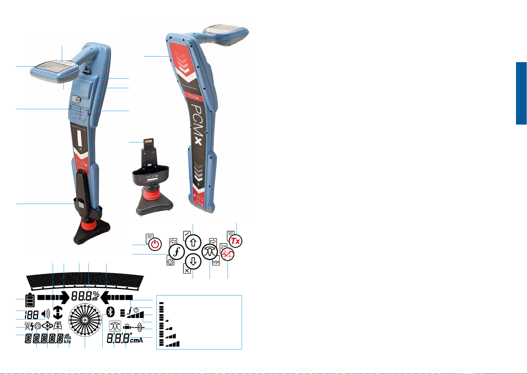
PCMx receiver
1
2
3
7
5
18 191923
17
20
21
22
24
25
26 27 28 30 3134 3229
Receiver features
1. Keypad.
9
4
10
8
6
2. LCD with auto backlight.
3. Speaker.
4. Lithium-Ion battery pack.
5. Removable magnetometer foot. Used
to detect the 4Hz mapping signal.
6. Connector for magnetometer foot
7. Accessory connector.
8. Headphone connector.
9. Bluetooth
®
module antenna.
10. USB port (inside battery
compartment).
29. Frequency / current / menu readout.
30. Bluetooth status icon: Flashing icon
means pairing is in progress. Solid
icon indicates a connection is active.
31. Antenna mode icon: Indicates
antenna mode selection: Peak /
Peak+ / Null / Broad Peak / Guidance.
32. Sonde icon: Indicates that a sonde
signal source is selected.
33. Line icon: Indicates that a line signal
source is selected.
34. Compass: Shows the orientation of
the located cable or sonde relative to
the receiver.
ENGLISH
35. Transmitter communication status
Receiver keypad
11. Power key.
12. Frequency key.
13. Up and down arrows.
14. Antenna key.
15. Survey key.
16. Transmitter key.
13
11
12
14 15
13
35
36
38
39
33
37
GPS
active, seeking satellite lock
GPS satellite lock acquired
3-5 satellites in view
6-8 satellites in view
9-11 satellites in view
12 or more satellites in view
16
Receiver screen icons
17. Signal strength bar graph with peak
marker.
18. Signal strength readout.
19. Null / Proportional Guidance arrows.
20. Battery level.
21. Sensitivity readout / Log number.
22. Volume level.
23. Current Direction or Fault Find arrows
(see note below).
24. Radio Mode icon.
25. Power Mode icon.
26. Accessory / Measurement icon.
27. CD Mode icon.
– conrms successful iLOC
communication. (Tx-1,Tx-5, Tx-10 only).
36. Transmitter standby indicator.
(Tx-1,Tx-5, Tx-10 only).
37. Depth readout.
38. GPS Status.
39. GPS Signal quality.
Current Direction arrows
NOTE! Different industry conventions have
developed for Current Direction arrows
and this is reected in the different modes
of use. In pipeline surveying the arrows
indicate the return path to earth. The utility
locating industry use the arrows to indicate
the path of the signal as it transmitted away
from the transmitter.
When the PCMx has the magnetometer
foot attached, a reverse arrow, (pointing
towards the Tx), on the receiver screen
indicates that the user is following the
correct cable or pipeline.
With the foot removed, a forward arrow,
(pointing away from the Tx), indicates the
user is locating the correct cable or pipeline.
™
28. A-Frame icon.
6 7
Page 5

Tx-150PCM & Tx-25PCM transmitters
10
2
3
7
10
4
2
3
8
The Tx-150PCM and the Tx-25PCM
Transmitter controls
are constant current transmitters which
transmit a 4Hz mapping frequency
suitable for pipeline surveys.
9
The Tx-150PCM (150W) allows for long
range signal detection of up to 30km
(20 miles). Signicantly fewer pipeline
connection points are needed thereby
4
reducing the time required to evaluate a
section of pipeline.
5
The Tx-25PCM (25W) has internal Li-ion
batteries that allow it to operate in the
eld independently of external power
sources.
6
Transmitter features
1. On/Off switch.
2. LCD display: Indicates current output,
(4Hz or 8kHz) in Amps.
3. LED indicators. Provide critical
feedback on the transmitter’s
operation.
4. AC Input socket.
5. DC Input socket (Tx-150PCM only).
6. Output lead socket.
10
6
9
7. Output Level Selector: Select the
output level in Amps.
8. Frequency Selector: Selects the
frequency.
9. Communication Port: For service
personnel only.
10. Heat sink: Vents heat from the
Frequency Select
The rotary switch selects the applied
frequencies as follows:
ELF Transmission lines
ELF Maximum range.
35% 4Hz and 65% ELF
(128Hz or 98Hz).
ELCD
Use for ACVG and current
direction.
35% 4Hz, 30% 8Hz and
35% ELF.
LFCD
Use as ELCD, alternative
locate frequency for congested
areas. 35% 4Hz, 30% 8Hz
and 35% LF (640Hz or 512Hz).
8kHz Locate only signal, no 4Hz
frequency for pipeline mapping.
Output Current Selector
This rotary switch allows users to select
different current settings.
The options are;
Tx-150PCM:
100mA, 300mA,
600mA, 1A, 2A,
3A
Tx-25PCM:
30mA, 60mA,
100mA, 300mA,
600mA, 1A
ENGLISH
transmitter during operation.
When the transmitter is operating, the
selected current will remain at a constant
level, unless the input power supply limit
is reached.
1
7
8 9
8
Page 6

Indication and warning lights
LCD Display: Displays the 4Hz or 8kHz
signal current that is being delivered
onto the pipe. On startup it conrms the
AC frequency setting and associated
location frequencies. The Tx-25PCM also
displays the battery level on startup.
Output
Voltage Level: Indicates the output
voltage levels. If no LED is lit the output
voltage is below 20V. Do not use
excessive voltage or current, as this may
result in high current density through
small holidays and coating defects.
The may cause minor corrosion if the
transmitter is left on for very long periods.
Voltage Limit: LED on.
Transmitter has reached its 100V output
voltage limit – resistance of the pipe or
ground connection is too high. Check all
connections to correct this problem.
NOTE: If the pipeline being surveyed
has coating that is known to be in good
condition, it is probable that the voltage
warning LED’s will illuminate as the
current is increased.
Undesirable voltage on output:
LED ashes. This indicates a high
voltage, such as mains, has been
detected on the output. The unit will
not operate until the cause of the high
voltage has been removed and the
transmitter has been reset by switching
it off, and on again.
Power Limit: System cannot
supply power required to
support transmission at the selected
current. Switch to a lower current setting
until the OK LED illuminates GREEN.
Allow a few seconds to settle between
selections.
Tx Over Temperature: Lights if
temperature exceeds recommended
limits. The transmitter will automatically shut
down. Wait until the transmitter has cooled
down before recommencing operation.
: Lights GREEN to indicate unit is
working correctly
Tx-25PCM only
Power: Indicates power supply
connected
Battery Charging: Indicates when
battery is charging. Lights ORANGE
when battery level is low. Lights Green
when battery is almost charged. When
fully charged the LED will turn off.
Battery Charge Temperature:
Indicates when battery is out of
temperature range for charging.
Tx-1, Tx-5 and Tx-10
transmitters
The PCMx can also be used with a
Radiodetection locating transmitter.
These transmitters do not produce a 4Hz
mapping signal but can be used to either:
• Boost the locate part of the signal when
the PCMx is being used for pipeline
surveys, (for more information see the
PCMx Operation Manual).
• Provide a wider range of locate signals
when the PCMx is being used in
RD8100 mode, as a precision cable
and pipe locator, (for more information
see the RD8100 Operation Manual).
Setting up your
PCMx receiver
Before you begin
IMPORTANT! This guide is intended
to be a quick reference guide. We
recommend you read the full operation
manual before you attempt to operate
the PCMx receiver or transmitters.
Rechargeable battery packs
Your PCMx comes with a Lithium-Ion
battery pack installed. To charge the
battery:
• Connect the battery charger to a
100-240VAC mains supply.
• Connect the battery charger to the
connector on the battery pack.
NOTE: It is not necessary to disconnect
the battery from the receiver for charging.
Switch on the mains supply. The charge
LED provides the battery pack charging
status as follows:
• Red = Charging
• Green = Fully Charged.
• Disconnect the charger once the
battery pack is fully charged
Checking your system
software version
If you wish to check which version
of software is running on your
PCMx, press and hold the
when switching on the receiver. This
information may be asked for when
contacting Radiodetection or your local
representative for technical support.
key
System setup
It is important that you set up the system
according to regional / operational
requirements, and your personal
preferences, before you conduct your rst
survey. You can set the system up using
the menus as described below.
The PCMx receiver menu allows you to
select or change system options. Once
entered, the menu is navigated using
the arrow keys. When in the menu, most
on-screen icons will temporarily disappear
and the menu options will appear in the
bottom left-hand corner of the display.
The right arrow enters a submenu and the
left arrow returns to the previous menu.
Note that when browsing the receiver
menu, the
right arrows.
To navigate menus:
1. Press the key to enter the menu.
2. Use the
through the menu options.
3. Press the
submenu.
4. Use the
through the submenu options.
5. Press the
and return to the previous menu.
6. Press the
operation screen.
NOTE: When you select an option and
press the
enabled automatically.
and keys act as left and
keys to scroll
or
key to enter the option’s
keys to scroll
or
key to conrm a selection
key to return to the main
key, the option will be
ENGLISH
10 11
Page 7

Receiver menu options
• VOL: Adjust the speaker volume from
0 (mute) to 3 (loudest).
• DATA: Delete, send or review saved
SurveyCERT measurements and
enable or disable the Bluetooth
communication channel.
• BT: Enable, disable, reset or pair
Bluetooth connections. Also denes the
protocol used when connecting to a PC
or PDA.
• GPS: Enable, disable or reset the
internal GPS module.
• CDR: Perform a Current Direction
(CD) Reset. (Alternatively press and
hold the
• UNITS: Select metric or imperial units.
• INFO: Run a Self-Test, display the date
of the most recent service recalibration
(M CAL) or the most recent eCert
calibration.
• LANG: Select menu language.
• POWER: Select local power network
frequency: 50 or 60Hz.
• ANT: Enable or disable any antenna
mode with the exception of Peak.
• FREQ: Enable or disable individual
frequencies.
• ALERT: Enable or disable StrikeAlert
• BATT: Set battery type: Alkaline or NiMH.
Li-Ion auto-selects when connected.
• ARROW: Select Null or proportional
Guidance arrows in Peak+ mode
• COMPA: Enable or disable display of
the Compass feature.
• TIME: Set a time to turn receiver off
after a period of inactivity.
• VIEW: Review survey measurements
(PCM mode only).
key when in CD mode).
™
Examples of using the
menu, selecting options
and making changes:
Receiver mains power frequency
NOTE: It is important to ensure your
receiver is set to locate the power
frequencies used in your country. If
the PCMx is set to the incorrect power
frequency, the user will have difculty
locating in Power, CPS, ELF and LF
modes as these locate frequencies are
all dependent upon the correct power
frequency.
To select the correct frequency (50 or
60Hz) for your country or region’s power
supply:
1. Press the
2. Scroll to the POWER menu using the
or
3. Press the
POWER menu.
4. Use the
correct mains frequency.
5. Press the
your selection and return to the main
operation screen.
Battery set up
The PCMx is supplied with a Lithium-Ion
.
rechargeable battery. The Li-Ion option
will automatically be selected when the
battery pack is connected to the receiver.
If you wish to use other battery types,
using the tray supplied, the appropriate
battery type must be selected.
To set your battery type:
1. Press the
2. Scroll to the BATT menu using the
or
arrows.
12 13
key to enter the menu.
keys.
key to enter the
keys to select the
or
key twice to accept
key to enter the menu.
3. Press the
key (transmitter) to enter the BATT
menu.
4. Scroll up or down to select the correct
battery type (Alkaline, Nickel-metal
Hydride or Lithium-Ion).
5. Press the
your selection and return to the main
operation screen.
key (receiver) or the
key twice to accept
Running a Self-Test
We recommend that a Self-Test is run at
least weekly, or before each use. As the
Self-Test tests the integrity of the locate
circuity, it is important that it is carried out
away from larger metallic object such as
vehicles, or strong electrical signals. To
run a Self-Test:
1. Ensure the magnetometer foot is
connected. The Self-Test will fail
without it.
2. Press the
3. Scroll to the INFO menu using the
or
arrows.
4. Press the
menu.
5. Select TEST using the
arrows.
6. Press the
7. Press the
Self-Test.
8. Once the Self-Test is completed,
the result (PASS or FAIL) will be
displayed.
9. Restart the receiver using the
key to enter the menu.
key to enter the INFO
or
key to select YES.
key to begin the
key.
Bluetooth wireless
connections
PCMx receivers feature a Bluetooth
wireless module, as standard, providing
the ability to connect to compatible
devices such as mobile devices running
a compatible application such as
PCM Manager or Bluetooth enabled
transmitters.
NOTE: The PCMx wireless features
may be subject to national and or local
regulations. Please consult your local
authorities for more information.
WARNING! Do not attempt any
wireless connection in areas where such
technology is considered hazardous.
This may include: petrochemical
facilities, medical facilities or around
navigation equipment.
Switching Bluetooth on
By default, PCMx receivers are shipped
with the Bluetooth wireless connection
module switched off.
1. Press the
2. Scroll to the BT menu using the
or
keys.
3. Press the
key (transmitter) to enter the BT menu.
4. Scroll up or down to the ON option.
5. Press the
ON and return to the previous menu.
You can switch Bluetooth off to conserve
battery life, or to comply with regulations
in areas where wireless communications
are considered hazardous. To do this,
follow the above process, selecting ‘OFF’
in the BT menus.
key to enter the menu.
key (locator) or the
key to switch Bluetooth
ENGLISH
Page 8

PCMx transmitter
signal connection
WARNING! Appropriate safety
procedures must be followed before
removing pipeline CP connection from
the rectier. Before handling connection
leads switch both the rectier and PCMx
transmitter OFF.
Connection to a rectier
A rectier station is an ideal place to
connect the output of a PCMx transmitter
as it provides connections to both pipe
and an anode bed for a suitable ground.
The rectier can also be used to power
transmitter using the mains supply. The
Tx-150PCM can also be powered from
the rectier output.
1. Disconnect both pipe and anode
cables from the rectier.
2. Ensure the transmitter is turned off.
3. Connect the White signal output lead
to the pipe cable.
4. Connect the Green signal output lead
to the anode cable.
Rectifier
(Disconnected)
Insulating
Joint
0
I
A
V
+
Mains
Supply
PCM Tx
Anode
When connection to a
rectier is not possible
Connection of a PCMx transmitter can be
made to a suitable test point or directly
to the pipeline itself. Connect the White
output cable to the connection that is
connected directly to the pipeline and
connect the Green output lead to either
a sacricial anode or use a suitable earth
stake.
If using a sacricial anode, make sure
that it is not directly connected to the
pipeline. When using an earth stake,
position the stake 45m / 150 feet away
from the pipe. To achieve a suitable
earth, it may be necessary to use more
than one earth stake linked together.
When connecting to an electrical
isolation joint, you may connect the
White lead to one side of the joint and
the Green output lead to the opposite
side of the pipe section as this can often
provide a suitable ground connection.
Conducting a
pipeline survey
Locate and pinpoint the pipe
A B
C
C
A
B
With the magnetometer foot attached,
switch on the PCMx receiver.
1. Use the
key to match the frequency
mode of the receiver to the operating
frequency of the transmitter. If you
intend to conduct a survey of the
pipeline, ensure both transmitter and
receiver are set to one of the mapping
frequencies, (ELF, ELCD or LFCD).
2. If you wish to capture location ensure
the internal GPS is switched on (see
details below).
3. Set the antenna mode to Peak+
by pressing the antenna key
The screen will display
.
Once in
Peak+, holding down the antenna
key alternates between adding
Guidance or Null modes to the Peak
reading. Add Guidance mode, by
holding the antenna key down; Guide
appears in the lower left corner of the
display. Two holds may be required
depending on the starting mode.
4. Use map information or pipeline
markers to determine an approximate
location for the pipe. Holding the
PCMx receiver upright at your side,
follow the guidance arrow to cross the
path of the pipe. Proximity to the pipe
is indicated by a rising bar graph and
an increase in tone when volume is
switched on.
Pinpointing denes the exact position
and direction of a pipeline after its
position is approximately known.
Pinpointing is important as the depth
and current readings are affected by
misalignment errors.
1. Adjust the receiver sensitivity to
approximately 50% by pressing
and
the
keys. This enables
changes in the bar graph to be more
readily seen.
2. Hold the PCMx upright and near to
the ground.
3. Move it slowly from side to side
and dene the point of maximum
response by looking at the bar graph.
The guide arrows should be at
minimum length.
4. To align the PCMx with the pipeline,
rotate the receiver until the compass
is in the 6 O’clock position.
™
The PCMx receiver features TruDepth
, a
feature that helps to ensure the accuracy
of locate or survey measurements. When
the receiver is not aligned correctly with
the pipe direction, the depth and current
measurements are automatically removed
from the display. The measurements
will also be removed when the receiver
determines that signal conditions are too
poor for reliable results.
Having pinpointed the pipe, the PCMx will
display the depth of the pipe, (measured to
the center of the pipe), and the current of
the locate signal. It is now possible, using
the guide arrows, to follow the pipeline.
ENGLISH
14 15
Page 9

To turn the internal GPS on:
1. Press the
2. Scroll to the GPS menu using the
keys.
or
3. Press the
menu.
4. Scroll to INT to select internal GPS.
5. Press the
your selection and return to the main
operation screen.
6. When a GPS lock has been acquired
the GPS lock symbol will display on
the screen. An indicator of the number
of satellites in view is also given.
key to enter the menu.
key to enter the GPS
key twice to accept
Conducting an ACCA survey
An Alternating Current, Current
Attenuation, (ACCA) survey measures the
attenuation of the transmitted 4Hz signal
to establish the pattern of current loss.
The results can be used to; establish the
condition of the pipeline coating, locate
faults, or nd shorts caused by contact
with other metal objects.
Having used the pinpointing method
above to ensure you are directly above
the correct pipeline, it is now possible to
take measurements of the 4Hz signal.
Procedure:
1. Use the peak response reading and
compass direction to ensure you are
directly above the pipeline.
2. Sit the receiver on the ground,
keeping it upright and very still.
3. Press and hold the
approximately one second. Upon
release a live 4Hz reading is
displayed on the bottom right of the
screen. It is normal for this reading
to uctuate within a couple of mA.
However, a widely uctuating reading
key for
may indicate interference and it may
be better to move along the pipeline
to take the measurement.
4. The reading can be stored by pressing
or rejected by pressing the
the
key. The PCMx can store up to 10,000
readings and the log number of the
stored reading will be shown on the
display.
5. Continue taking readings in this way
along the length of the pipeline you
wish to survey
6. For best results, readings should be
taken at intervals of equal distance.
NOTE: If Bluetooth is switched on, the
PCMx receiver will automatically attempt
to send the reading via Bluetooth to
a paired device. If the PCMx has not
been paired, a BT error code will be
displayed. If it is intended to only save
the reading internally within the PCMx
receiver, switch the BT-PC setting in the
DATA menu to OFF.
To overwrite a saved result, select the
result log and press
measurement is taken, press the
to overwrite the selected reading. The
log number that was overwritten will be
displayed and the receiver will revert to
storing new measurements at the end of
the current records.
. Once a new
key
Conducting an ACVG survey
An Alternating Current Voltage Gradient,
(ACVG), survey measures the leakage
current in the vicinity of the pipeline
to assess the coating condition, and
pinpoint coating defects. An advantage
of this survey method is that it can be
done on a route parallel to the pipe. For
example, it may be done on a pavement
or grass verge parallel to a pipe running
below a road surface. It requires the use
of an A-Frame in addition to the PCMx
receiver and transmitter.
Temporary measurements
In some situations, it can be difcult to view
the display when taking a measurement.
A temporary measurement can be taken
for review before committing the record
to memory. Take the measurement as
detailed above, but instead of pressing
the save or delete key, press the antenna
key
The measurement will be held
on screen for review. To save the
measurement, press
.
Review and Overwrite
Measurement Logs
Saved readings within the PCMx can be
reviewed or overwritten. To view a saved
result, press
and select VIEW. The last saved result will
be displayed. To view other logs, use the
or
16 17
to enter the system menu
keys to step through.
Procedure:
1. Connect the transmitter to the pipeline
and ground using the procedure
described previously.
2. Set the PCMx transmitter to either
ELCD or LFCD mode.
3. Connect the A-frame to the PCMx
receiver via the accessory socket,
and turn on the receiver.
4. The PCMx will automatically choose
ACVG mode and an A-frame symbol
will be displayed.
5. Choose an appropriate starting point
for your survey. If a suspected fault
location has been identied from a
previous ACCA survey, begin the
survey approximately 60 feet, (20
meters) from the suspected fault.
6. Place the A-frame spikes in the
ground above, or parallel with,
the pipe. Position the green spike
forwards and the red spike towards
the transmitter connection point.
7. If no fault is apparent, the arrows
will icker on and off and the dB
readings will be erratic. When a fault
is present, the Fault Find, (FF) arrows
will display the fault direction and the
dB readings will be stable. The dB
reading will increase as the A-Frame
is positioned closer to the fault.
8. Follow the pipeline pushing the
A-Frame spikes into the ground at
regular intervals and checking for
FF arrows.
9. Move in the direction of the arrows.
Find the point at which the arrows
change direction. If the A-frame has
been positioned directly above the
pipe, the fault location will be directly
below the A-Frame at this point.
10. If the measurements have been taken
to the side of the pipe line, rotate the
A-Frame 90° so that the green spike
points towards the pipeline. Move
back and forth across the pipeline to
locate the fault in this direction, the
intersection point will be directly over
the fault.
ENGLISH
Page 10

Conducting survey types
simultaneously
The PCMx allows users to conduct
both an ACCA and an ACVG survey
simultaneously. By collecting the data in
one pass of the pipeline, rather that two,
survey time can be reduced signicantly.
Procedure:
1. Connect the transmitter to the pipeline
and ground using the procedure
described previously.
2. Set the PCMx transmitter to either
ELCD or LFCD mode.
3. Connect the A-frame to the PCMx
receiver via the accessory socket,
and turn on the receiver.
4. The PCMx will automatically select
ACVG mode and an A-frame symbol
will be displayed.
5. Match the mode of the receiver to the
transmitter by repeated presses of the
key.
6. Begin your survey by following the
procedures given above for conducting
an ACVG survey. The display will
show locate information (Peak-PLUS
mode) and FF information.
7. To take a 4Hz current reading, follow
steps 2 through 6 of the procedures
given above for conducting an ACCA
survey.
PCM Manager
for mobile devices
Available from Google Play Store,
PCM Manager for mobile devices is
a companion application for PCMx
receivers. It enables live graphing of
survey results, walk forward and walk
back features. It can also be used to
collect location data from compatible
GPS devices. After installing the software
on your mobile device select the PCM
Manager icon.
Prepare the PCMx receiver to pair by
selecting the BT option in the system
menu. Scroll to PAIR and press the
key to select the BT – PC option.
ON your Android device ensure
Bluetooth is switched on. Launch PCM
Manager and choose the menu option on
the top left. Select Pairing.
Press SEARCH FOR DEVICES. On
the PCMx receiver press the
initiate pairing. The name of the device
will appear underneath BLUETOOTH
DEVICES FOUND.
key to
Select the device name. A prompt for
the pairing code will appear. Insert 1234
and press OK. The device name will now
appear under Paired Devices.
Press
Select START SURVEY to begin a
survey. Each time you take a survey
measurement, it will appear on the screen
and a graph will appear over time. Select
FINISH SURVEY to end the survey.
For more information about the
application, select Manuals from the PCM
Manager menu or download the manual
from www.radiodetection.com/PCMx
to return to the main screen.
ENGLISH
18 19
Page 11

PCM Manager
PC Software
PCM Manager PC software is also
available. The PC application allows the
user to download survey data from the
eld for analysis. It is compatible with
PCs running Microsoft Windows XP, 7, 8,
8.1 and 10. To download PCM Manager,
go to www.radiodetection.com/PCMx
If you do not have internet access, or
wish to receive PCM Manager on a CD-
ROM, contact your local Radiodetection
ofce or representative.
For more information about PCM
Manager PC software refer to the PCM
Manager operation manual.
Training
Radiodetection provides training services
for most Radiodetection products. Our
qualied instructors will train equipment
operators or other personnel at your
preferred location or at Radiodetection
headquarters. For more information go
to www.radiodetection.com or contact
your local Radiodetection representative.
Care and
maintenance
The PCMx receiver and transmitters
are robust, durable and weatherproof.
However, you can extend your
equipment’s life by following these care
and maintenance guidelines.
General
Store the equipment in a clean and dry
environment.
Ensure all terminals and connection
sockets are clean, free of debris and
corrosion and are undamaged.
Do not use this equipment when
damaged or faulty.
Batteries and power supply
Only use the rechargeable battery packs,
chargers and power supplies approved
by Radiodetection.
If not using rechargeable packs, use good
quality Alkaline or NiMH batteries only.
Batteries should be disposed of in
accordance with your company’s work
practice, and/ or any relevant laws or
guidelines in your country.
Cleaning
WARNING! Do not attempt to clean
this equipment when it is powered
or connected to any power source,
including batteries, adapters and live
cables.
Ensure the equipment is clean and dry
whenever possible.
Clean with a soft, moistened cloth. Do
not use abrasive materials or chemicals
as they may damage the casing,
including the reective labels. Do not use
high pressure jets of water to clean the
equipment.
If using this equipment in foul water
systems or other areas where biological
hazards may be present, use an
appropriate disinfectant.
Software upgrades
From time to time, Radiodetection may
release software upgrades to enhance
features and improve performance of the
PCMx receiver. Software upgrades are
free of charge and provided through the
PCM Manager PC software.
E-mail alerts and notication of new
software releases are sent to all
registered users. You can also check if
your products are up-to-date or upgrade
them by using the PCM Manager
software upgrade screen.
NOTE: To upgrade your product’s
software you need to have created an
account using PCM Manager and have a
live internet connection.
Disassembly
Do not attempt to disassemble this
equipment under any circumstances.
The receiver and transmitter contain
no user serviceable parts.
Unauthorized disassembly will void
the manufacturer’s warranty, and may
damage the equipment or reduce its
performance.
Service and maintenance
Regularly check your equipment for
correct operation by using the Self-Test
function and eCert.
The receiver and transmitter are
designed so that they do not require
regular recalibration. However, as with all
safety equipment, it is recommended that
they are serviced and calibrated at least
once a year either at Radiodetection or
an approved repair center.
NOTE: Service by non-approved service
centers may void the manufacturer’s
warranty.
Details of Radiodetection ofces and
distribution partners can be found at
www.radiodetection.com.
Radiodetection products, including this
guide, are under continuous development
and are subject to change without
notice. Go to www.radiodetection.com
or contact your local Radiodetection
representative for the latest information
regarding the PCMx receiver or any
Radiodetection product.
ENGLISH
Copyright © 2017 Radiodetection Ltd. All rights reserved. Radiodetection is a subsidiary of SPX Corporation. Radiodetection and PCMx are
registered trademarks of Radiodetection in the United States and/or other countries. The following are trademarks of Radiodetection: PCMx,
RD8100, eCert, iLOC, TruDepth, SideStep, SideStepauto, PCM Manager, Peak+, SurveyCERT, StrikeAlert, CALSafe, Current Direction. The
Bluetooth word, mark and logos are registered trademarks of Bluetooth SIG, Inc. and any use of such trademarks by Radiodetection is under
license. Due to a policy of continued development, we reserve the right to alter or amend any published
specication without notice. This document may not be copied, reproduced, transmitted, modied or used, in
whole or in part, without the prior written consent of Radiodetection Ltd.
20 21
Page 12

序言
关于本指南
注意:本指南提供了 PCMx 接收机和发射机的基本操作说明。本指南中包含重要的安全信
息和指导,在操作 PCMx 接收机和发射机前应完整阅读本指南。
本指南仅用作快速参考指南。有关详细说明,包括配件的使用,eCert™、CALSafe™
、探测测量以及使用记录的帮助,请参考 PCMx 操作手册和 PCM Manager 手册。取
下磁力计支脚后,PCMx 将自动被配置为 RD8100 PDLG 电缆和管道定位器。有关其
用作电缆和管道定位的附加说明,请参见 RD8100 操作手册。所有手册均可从
www.radiodetection.com 网站进行下载。
3 三年延长质保
PCMx 接收机和发射机的标准质保期为 1 年。顾客可以在购买产品后 3 个月内,通
过产品注册将质保期延长至 3 年。
产品注册要通过 PCM Manager 电脑软件完成,可从雷迪网站上下载该软件。请访
问 www.radiodetection.com/PCMx。
您还可以通过发送电子邮件至 rd_support@spx.com 注册您的产品,电子邮件需
包含以下详细信息:
• 每个需注册产品的序列号
英文
PCMx 和 Tx 发射机系列的合格证书请见 www.radiodetection.com。
警告!和带电导体直连可能具有致命危险。与带电导体的直连仅可由具有充分资质
的人员操作,并仅使用允许和通电线路连接的相关产品。
警告!发射机能输出具有可致命的电压。将信号引用于管道或线缆时应注意,要确
保通知可能在线路上工作的其他技术人员。
警告!使用耳机前,应降低音量,避免损伤您的听力。
警告!在可能存在有害气体的区域不得使用本设备。
警告!PCMx 接收机可探测到大部分埋设导体,但有部分物体并不发射出任何可探
测的信号。由于 PCMx 或任何其它电磁接收机无法探测到这些物体,因此在操作时要小
心谨慎。还存在一些 PCMx 在电力模式无法探测到的带电线缆。PCMx 无法表明信号是
来自单个线缆还是来自紧密靠近的若干线缆。
警告!在全功率输出下长时间使用后,电池可能变热。
在更换或处理电池时要小心谨慎。
警告!在标准接地条件和未失真场下,深度精度为 ±5% 或更好。如果您打算挖掘一
个定位管道,必须适当注意人身伤害和基础设施损坏的危险。建议在整个挖掘过程中重
复进行深度测量。
• 购买日期
• 公司名称与地址(包括国家)
• 联系人姓名、电邮地址与电话号码
• 居住国家。
雷迪可能不时发布新的软件,来提升这些产品的性能或增加新功能。通过产品注
册,用户可获得电邮订阅提醒,了解产品相关的新软件和特别优惠及服务。
用户可以随时选择停止接收软件和技术通知,或通过联系雷迪选择停止接收营销材
料。
eCert 与自检
PCMx 接收机是一种安全设备,应定期进行检查,确保其正常运行。
eCert 可对 PCMx 定位电路(包括磁力计脚)进行全面测试,如果测试结果合格,
将提供雷迪标定证明。
要运行 eCert,应打开磁力计脚并将接收机与连网的电脑相连,且该电脑上已安装
PCM Manager 软件。注:在没有磁力计脚的情况下进行测试将导致“失败”。
有关更多信息,请参考 PCM Manager 操作手册。该软件可能需要另外购买。
PCMx 接收机包含增强自检功能。除了对屏显与电源功能的必要检测外,PCMx 在
自检中还会将信号施加在定位电路上,以检查设备精度和性能。
建议至少每周或每次使用之前对设备进行一次自检。
22 23
Page 13
PCMx 接收机
1
2
3
7
5
17
20
21
22
24
25
26 27 28 30 3134 3229
接收机功能
1. 键盘。
2. 含自动背光的 LCD 显示屏。
9
3. 扬声器。
4. 锂电池组。
4
10
5. 可拆卸磁力计脚。用于检测 4Hz 映射
信号。
6. 磁力计脚连接器
8
7. 配件连接器。
8. 耳机连接器。
9. 蓝牙模块天线。
10. USB 端口(位于电池盒内部)。
6
接收机键盘
11. 电源键。
12. 频率键。
13. 上下箭头。
14. 天线键。
15. 探测键。
16. 发射机键。
30. 蓝牙状态图标:图标闪烁则表示正在
进行配对。若图标常亮,则表示已经
建立连接。
31. 天线模式图标:表示天线模式选择:
峰值/峰值+/谷值/宽峰值/导向。
32. 探头图标:表示已经选定一个探头信
号源。
33. 管线图标:表示已经选定一个管线信
号源。
34. 罗盘:表示定位管线或探头与接收机
的相对方向。
35. 发射机通信状态——确认 iLOC™ 通信
成功。(仅限 Tx-1、Tx-5、Tx-10)。
36. 发射机待机指示器。
(仅限 Tx-1、Tx-5、Tx-10)。
37. 深度读数。
38. GPS 状态。
39. GPS 信号质量。
电流方向箭头
注!电流方向箭头有不同的行业惯例,这反
映在不同的使用模式中。在管道探测中,箭
英文
头表示接地的返回路径。公用事业定位行业
13
16
接收机屏幕图标
17. 带峰值标识的信号强度图表。
11
12
18 191923
18. 信号强度读数。
19. 谷值/比例导向箭头。
20. 电量图标。
21. 灵敏度读数/日志号。
22. 音量图标。
14 15
13
35
36
38
39
33
37
GPS 启动,寻找卫星锁定
已获取 GPS 卫星锁定
3-5 颗卫星探测到
6-8 颗卫星探测到
9-11 颗卫星探测到
12 颗或更多卫星探测到
23. 电流方向和故障查找箭头(请参见下
面的注释)。
24. 无线电模式图标。
25. 电源模式图标。
26. 配件或测量指示器图标。
27. CD 模式图标。
28. A 型图标。
使用箭头来指示远离发射机的信号路径。
当 PCMx 连接了磁力计脚时,接收机屏幕上
的反向箭头(指向 Tx 的方向)说明用户正
在跟踪正确的电缆或管道。
当磁力计脚被移除时,向前箭头(指向远离
Tx 的方向)说明用户正在定位正确的电缆
或管道。
29. 频率/电流/菜单读数。
24 25
Page 14

Tx-150PCM 和 Tx-25PCM 发射机
10
2
3
7
10
4
2
3
8
Tx-150PCM 和 Tx-25PCM 是传输适合于
发射机控制
管道测量的 4Hz 映射频率的恒流发送器。
Tx-150PCM(150W)能使信号的检测距
离长达 30 公里(20 英里)。它需要明显
9
更少的管道连接点,从而减少评估一段管
道所需的时间。
Tx-25PCM(25W)具有内部锂电池,允
许其在独立于外部电源的情况下在现场进
4
5
行操作。
发射机功能
1. 开/关按钮。
2. LCD 显示屏:表示安培的电流输出
(4Hz 或 8kHz)。
6
3. LED 指示灯。提供有关发射机操作的
关键反馈。
4. 交流电源输入插口。
频率选择
旋转开关选择应用的频率如下:
ELF 传输线
ELF 最大范围。
35% 4Hz 和 65% ELF
(128Hz 或 98Hz)。
ELCD
LFCD
8kHz 仅定位信号,没有 4Hz 频率用
用于 ACVG 和电流方向。
35% 4Hz、30% 8Hz 和
35% ELF。
用于 ELCD、拥塞区域的替代
定位频率。35% 4Hz、30%
8Hz 和 35% ELF(640Hz 或
512Hz)。
于管道
英文
5. 直流电源输入插口(仅限 Tx150PCM)。
6. 输出线缆插座。
7. 输出水平选择器选择以安培为单位的
输出水平。
8. 频率选择器:选择频率。
9. 通讯端口:仅供维修人员使用。
10. 热沉:在运行期间排出发射机的热
10
量。
输出电流选择器
该旋转开关允许用户选择不同的电流设
置。
选项包括:
Tx-150PCM:
100mA、
300mA、
600mA、
1A、2A、3A
6
9
Tx-25PCM:
30mA、60mA、
100mA、
300mA、
600mA、1A
当发射机正在运作时,除非达到输入电源
极限,否则所选电流将保持在恒定。
1
7
26 27
8
Page 15

指示灯和警告灯
LCD 显示屏:显示输送到管道上的 4Hz
或 8kHz 信号电流。在启动时,它确认
了 AC 频率设置和相关的位置频率。Tx25PCM 还会在启动时显示电池电量。
输出电压
水平:表示输出电压水平。如果 LED 灯
没有亮起,这意味着输出电压低于 20V。
请勿使用过高的输出电压或输出电流,因
为这样可能在管道泄漏处或涂层破损点产
生很高的电流密度。长时间施加信号会造
成轻度腐蚀。
电压限值:LED 灯亮。发射机
已到达 100V 输出电压限值——管道电阻
或大地电阻过高。检查所有连接以纠正此
问题。
注:如果被测管道具有已知处于良好状态的
涂层,则电流警告 LED 可能随着电流增加
而发亮。
输出电压不合要求:
LED 灯闪烁。这表示在输出上检测到高电
压(例如电源)。在高电压的原因被消除
并且发射机已经通过关闭并重新打开后被
复位之前,设备将不会运作。
功率超限:系统无法按选定电
流输出提供发射电能。切换到
较低的电流设置,直到 OK LED 灯变为绿
灯。电流调整后需几秒钟才会稳定。
Tx 温度过高:如果温度超过建议的
限制,指示灯将亮起。发射机会自
动关机。等发射机冷却后才能再开机。
: 设备运作正常时亮绿灯
仅限 Tx-25PCM
电源:表示电源已连接
电池充电:表示电池正在充电。电池
电量低时亮橙色。电池几乎充满时亮
绿色。当充满电时,LED 将熄灭。
电池充电温度:表示电池超出充电温
度范围。
Tx-1、Tx-5 和 Tx-10
发射机
PCMx 还可以与雷迪定位发射机一起使
用。这些发射机不产生 4Hz 测绘信号,但
可以用于:
• 当 PCMx 用于管道探测时,提高信号
的定位部分(欲知更多信息,请参阅
PCMx 操作手册)。
• 当在 RD8100 模式下使用 PCMx 作为
精密电缆和管道定位器时(欲知更多信
息,请参见“RD8100 操作手册”),
提供更宽范围的定位信号。
设置您的 PCMx 接
收机
在您开始之前
重要提示!本指南仅作为快速参考指南使
用。我们建议您在操作 PCMx 接收机或发射
机前,先阅读完整的操作手册。
可充电电池组
您的 PCMx 配备了一个锂电池组。为电
池充电:
• 将电池充电器连接到 100-240VAC 主
电源。
• 将电池充电器连接到电池组上的连接
器。
注:无需断开电池与接收器的连接以进行充
电。
打开电源。充电 LED 灯提供以下的电池
组充电状态:
• 红色 = 正在充电
• 绿色 = 充满电。
• 一旦电池组充满电,请断开充电器
检测您的系统软件版本
如需检测您的 PCMx 上运行的软件版本,
请打开接收机并按住
雷迪或您当地的技术支持代表时询问版本
信息。
键。还可在联系
系统设置
进行首次操作之前,您可以根据区域/操
作要求和您的个人偏好来设置系统,这一
点很重要。您可以使用下面的菜单来设置
系统。
通过 PCMx 接收机和发射机菜单,您可以
选择或更改系统选项。进入菜单后,会有
箭头键来导航菜单。在菜单中,屏幕上的
大部分图标会暂时消失,在显示屏左下角
会出现菜单选项。
点击右箭头,将进入子菜单,点击左箭头
则会返回到上一级菜单。
请注意,在浏览接收机菜单时,
键将作为左右箭头使用。
导航菜单:
1. 按下 键进入菜单。
2. 使用
3. 按下
4. 使用
动。
5. 按下
单。
6. 按下
注:当您选择某一选项,并按下 键时,
将自动启用该选项。
或 键在菜单选项中滚动。
键进入选项的子菜单。
或 键在子菜单选项中滚
键确认选择并返回上一个菜
键返回主操作屏幕。
键和
英文
28 29
Page 16

接收机菜单选项
• VOL:在 0(静音)和 3(最高)之间
调节扬声器的音量。
• DATA:删除、发送或审阅所保存的
SurveyCERT 测量数据,并启用或禁用
蓝牙通讯频道。
• BT:启用、禁用、重设或配对蓝牙连
接。在接入个人电脑或个人掌上电脑
(PDA)时,将确定所使用的协议。
• GPS:启用、禁用或重设内部 GPS 模
块。
• CDR:电流方向(CD)重设。(处于
CD 模式时,按住
• UNITS:选择公制或英制。
• INFO:进行自检、显示最近重新标定
(M CAL)或最近 eCert 标定的日期。
• LANG:选择菜单语言。
• POWER:选择本地电力网络频率:50
或 60Hz。
• ANT:启用或禁用任何天线模式,峰值
模式除外。
• FREQ:启用或禁用单个频率。
• ALERT:启用或禁用 StrikeAlert
• BATT:设置电池类型:碱性或镍氢。
连接后,锂离子自动选择。
• ARROW:在峰值+模式中选择谷值或
比例导向箭头
• COMPA:启用或禁用罗盘功能的显
示。
• 时间:设定在一段时间不活动后关闭接
收机。
• VIEW:查看探测测量(仅限 PCM 模
式)。
键)。
™
。
菜单使用、选项选择以及更
改操作示例:
接收机主电源频率
注:确保您的接收机设置为定位用于您所在
国家/地区的电源频率这一点很重要。如果
PCMx 设置为不正确的电源频率,用户将难
以在电源、CPS、ELF 和 LF 模式中进行定
位,因为这些定位频率都取决于正确的电源
频率。
请选择您所在国家或地区合适的电源频率
(50 或 60Hz):
1. 按下
2. 使用
3. 按下
4. 使用
率。
5. 按两次
回到主操作屏幕。
电池设置
PCMx 配备了一个可充电锂电池。
当电池组连接到接收器时,将自动选择锂
离子选项。如果要使用其他电池类型,请
使用随附的托盘,选择适当的电池类型。
设置您的电池类型:
1. 按下
2. 使用
3. 按下
机)进入 BATT 菜单。
4. 向上或向下滚动,选择正确的电池类
型(碱性电池、镍氢电池或锂电池)
。
5. 按两次
回到主操作屏幕。
键进入菜单。
或 键滚动至电源菜单。
键进入电源菜单。
或 键选择合适的电源频
键以确认您的选择,然后返
键进入菜单。
或 键滚动至 BATT 菜单。
键(接收机)或 键(发射
键以确认您的选择,然后返
运行自检
建议至少每周或每次使用之前对设备进行
一次自检。自检主要检测定位电路的完好
性,因此自检时应远离大型金属物体,例
如车辆或强电力信号,这一点尤为重要。
若要运行自检功能:
1. 确保已连接磁力计脚。如果没有磁力
计脚,自检将失败。
2. 按下
3. 使用
4. 按下
5. 使用
6. 按下
7. 按下
8. 一旦完成自检,结果(通过或失败)
将显示在屏幕上。
9. 使用
键进入菜单。
或 键滚动至 INFO 菜单。
键进入 INFO 菜单。
或 箭头选择 TEST。
键选择“YES”。
键开始自检。
键重新启动接收机。
蓝牙无线连接
PCMx 接收机的标配包含蓝牙无线模块,
能够和兼容设备相连,例如运行兼容程序
(如:PCM Manager)的手持设备或具
有蓝牙功能的发射机。
注:PCMx 无线功能需要遵守本国或当地规
定。请咨询您当地部门了解更多信息。
警告!不要在无线连接技术可能存在危
险的区域使用该连接。这些区域可能包括:
石化设施,医疗场所或导航设备周围。
打开蓝牙
PCMx 接收机在运送时已默认禁用蓝牙无
线连接模块。
1. 按下
2. 使用
3. 按下
机)进入 BT 菜单。
4. 上下滚动至 ON 选项。
5. 按下
菜单。
您可以关闭蓝牙以延长电池寿命,或在将
无线连接视为危险的区域遵守相关规范。
要关闭蓝牙,请遵照上述操作过程,在
BT 菜单中选择‘OFF’按钮。
键进入菜单。
或 键滚动至 BT 菜单。
键(定位仪)或 键(发射
键,打开蓝牙,返回上一个
英文
30 31
Page 17

PCMx 发射机信号
连接
警告!在从整流器去除管道 CP 连接之
前,必须遵循适当的安全程序。在处理连接
导线之前,请关闭整流器和 PCMx 发射机。
连接到整流器
整流器站是连接 PCMx 发射机输出的理想
场所,因为它提供与两个管道的连接和用
于合适接地点的阳极床。整流器也可用于
使用主电源为发射机供电。Tx-150PCM
也可以从整流器输出供电。
1. 断开整流器的管道和阳极电缆。
2. 确保发射机电源断开。
3. 将白色信号输出线与管道线缆连接。
4. 将绿色信号输出线连接到阳极线缆。
Rectifier
(Disconnected)
Insulating
Joint
0
I
A
V
+
Mains
Supply
PCM Tx
Anode
当无法连接到整流器时
可以将 PCMx 发射机连接到合适的测试
点或直接连接到管道本身。将白色输出电
缆连接到直接连接到管道的连接点,并将
绿色输出线连接到牺牲阳极或使用合适的
接地棒。
如果使用牺牲阳极,确保没有直接连接到
管道上。当使用接地棒时,接地棒必须离
开管道至少 45 尺(150 尺)。为了实现
合适的接地,可能需要使用多个连接在一
起的接地棒。
当连接到电气隔离接头时,您可以将白色
导线连接到接头的一侧,绿色输出线连接
到管道部分的相对侧,因为这通常可以提
供合适的接地连接。
开展管道探测
找到并精确定位管道
C
A B
C
A
B
连接磁力计支脚后,打开 PCMx 接收机。
1. 使用
键将接收机的频率模式与发
射机的工作频率相匹配。如果您打
算对管道进行探测,请确保发射机
和接收机均设置为其中一个测绘频率
(ELF、ELCD 或 LFCD)。
2. 如果要捕获位置,请确保内部 GPS 已
打开(请参阅下面的详细信息)。
3. 按下天线键
值+。屏幕将显示
,将天线模式设置为峰
峰值+,按住天
线键将导向或谷值模式添加到峰值读
数之间交替。通过按住天线键以添加
导向模式;导向显示在显示屏的左下
角。根据启动模式,可能需要按两次
天线键。
4. 使用地图信息或管道标记来确定管道
的大致位置。将 PCMx 接收机垂直放
在您身边,按照指示箭头穿过管道的
路径。上升条形图和音量打开时的音
调增加表示与管道的接近程度。
在追踪了目标管线,并且知道其大致方位
后,定点定位便能确定目标管线的精确位
置和走向。定点定位是很重要的,偏差直
接影响深度和电流读数的精确度。
1. 按下
和 键,将接收机灵敏度调
至 50%。这使得能够更容易地看到条
形图的改变。
2. 手提 PCMx,使其垂直接近地面。
3. 在管道的一侧和另一侧缓慢来回移
动,通过查看条形图确定最大响应位
置。引导箭头应为最小长度。
4. 要将 PCMx 与管道对准,请旋转接收
机,直到罗盘处于 6 点钟位置。
™
PCMx 接收机具有 TruDepth
功能,该功
能可以确保您的定位或探测测量值的准确
性。当接收机未与管道方向正确对齐时,
显示器会自动清除深度和电流数据。当接
收机确定信号条件太差无法进行可靠测量
时,测量也将被移除。
在精确定位管道后,PCMx 将显示管道的
深度(测量到管道的中心)和定位信号的
电流。现在可以使用引导箭头跟随管道。
英文
32 33
Page 18

要打开内部 GPS:
1. 按下 键进入菜单。
2. 使用
3. 按下
4. 滚动至 INT 选择内部 GPS。
5. 按两次
回到主操作屏幕。
6. 当获得 GPS 锁定时,屏幕上将显示
GPS 锁定符号。此外还显示了卫星数
量的指标。
或 键滚动至 GPS 菜单。
键进入 GPS 菜单。
键以确认您的选择,然后返
开展 ACCA 探测
交流电流、电流衰减、(ACCA)探测测
量所传输 4Hz 信号的衰减,以建立电流损
耗的模式。结果可用于:建立管道涂层的
状况、定位故障或找到与其他金属物体接
触所引起的短路。
使用上面的精确定位方法确保您位于正确
的管道上方,现在可以测量 4Hz 信号。
程序:
1. 使用峰值响应读数和罗盘方向,以确
保您直接位于管道上方。
2. 将接收机放在地面上,保持直立且一
动不动。
3. 按住
下方将显示 4Hz 的实时读数。这个读
数在几 mA 内出现波动是正常的。然
而,大幅波动的读数可能表明干扰,
沿着管道进行探测可能会更好。
4. 按
键拒绝。PCMx 可以存储多达 10,000
个读数,而显示屏上将显示已存储读
数的记录编号。
5. 沿着您想要测量的管道长度继续读取
读数
6. 为获得最佳结果,应按一定的间隔进
行测量。
键约一秒钟。释放后,屏幕右
键可以存储读数,或者可按
注:如果已打开蓝牙,PCMx 接收机将自
动尝试通过蓝牙将读数发送到已配对的设备
上。如果尚未配对 PCMx,将显示 BT 错误
代码。如果仅打算在 PCMx 接收机内部保存
读数,请将 DATA菜单中的 BT-PC 设置切
换到 OFF。
临时测量
在某些情况下,进行测量时可能难以查看
显示。在将记录提交到记忆之前,可以进
行临时测量以进行审查。进行上述测量,
但不按下保存或删除键,而是按下天线键
。测量将保留在屏幕上以供查看。要保
存测量,请按
。
查看和覆盖测量日志
PCMx 中保存的读数可以被检查或覆盖。
要查看保存的结果,请按
单,然后选择 VIEW。最后保存的结果将
被显示。要查看其他记录,请使用
键逐步执行。
要覆盖保存的结果,请选择结果记录,然
后按
覆盖所选读数。该被覆盖的记录编号将被
显示,并且该接收机将恢复到在当前记录
结束时存储新测量。
。一旦进行新的测量,按 键以
进入系统菜
或
进行 ACVG 探测
交流电压梯度(ACVG)探测将测量管道
附近的泄漏电流,以评估涂层状况,并确
定涂层缺陷。这种探测方法的优点是可以
在与管道平行的路径上完成。例如,它可
以在平行于在路面下方行进的管道的路面
或草地边缘上进行。除 PCMx 接收机和发
射机外,它还需要使用 A 字架。
程序:
1. 使用先前描述的方法,将发射机连接
到管道和地面。
2. 将 PCMx 发射机设置为 ELCD 或
LFCD 模式。
3. 通过附件插口将 A 字架连接到 PCMx
接收机,并打开接收机。
4. PCMx 将自动选择 ACVG 模式,并显
示 A 字架符号。
5. 为您的探测选择适当的起点。如果从
先前的 ACCA 探测中识别出疑似故障
位置,则从可疑故障开始大约 60 尺
(20 米)处开始测量。
6. 将 A 字架的脚钉放在地面上或与管道
平行。将绿色脚钉向前放置,红色脚
钉朝向发射机连接点。
7. 没有故障时,箭头将前后闪烁不定,
而且 dB 读数将不稳定。当存在故障
时,故障查找(FF)箭头将显示故障
方向,而且 dB 读数将稳定。当 A 字
架接近故障点时,dB 值将会增大。
8. 沿着管道以定期的间隔将 A 字架脚钉
插入地面并检查 FF 箭头。
9. 沿箭头方向移动。找到箭头改变方向
的点。如果 A 字架位于管道的正上
方,则故障点将直接在 A 字架下方。
10. 如果测量已经到达管道侧面,请将 A
字架旋转90°,使得绿色脚钉指向管
道。在管道上来回移动,并以这个方
向定位故障,中心点就在故障点的正
上方。
英文
34 35
Page 19

同时进行探测类型
PCMx 允许用户同时进行 ACCA 和 ACVG
探测。通过在管道的一次通过中收集数
据,而不是两次,这将可明显减少探测时
间。
程序:
1. 使用先前描述的方法,将发射机连接
到管道和地面。
2. 将 PCMx 发射机设置为 ELCD 或
LFCD 模式。
3. 通过附件插口将 A 字架连接到 PCMx
接收机,并打开接收机。
4. PCMx 将自动选择 ACVG 模式,并显
示 A 字架符号。
5. 通过重复按
的模式相匹配。
6. 按照上面给出的程序进行 ACVG 探
测。显示屏将显示定位信息(峰值+模
式)和 FF 信息。
7. 要采取 4Hz 的电流读数,按照上面给
出的步骤 2 到 6 进行 ACCA 探测。
键,使接收机与发射机
适用于移动设备的
PCM Manager
适用于移动设备的 PCM Manager 是
PCMx 接收机的配套应用程序。可从
Google Play 商店下载。它可以实时绘制
探测结果,并具有前进和后退特征。它
也可以用于从兼容的 GPS 设备收集位置
数据。在移动设备上安装软件后,选择
PCM Manager 图标。
通过选择系统菜单中的 BT 选项,准备配
对 PCMx 接收机。滚动到 PAIR 并按
键选择 BT - PC 选项。
确保您 Android 设备上的蓝牙已打开。启
动 PCM Manager,并选择左上角的菜单
选项。选择配对。
按搜索设备。在 PCMx 接收机上按
启动配对。设备名称将显示在找到蓝牙设
备下方。
选择设备名称。将出现配对代码的提示。
输入 1234,然后按 OK。设备名称现在将
显示在已配对设备下。
英文
键
36 37
键返回主屏幕。选择开始探测以开
按
始探测。每次进行探测测量时,它就会出
现在屏幕上,而且图形会出现一段时间。
选择完成探测以结束探测。
如需了解更多有关应用程序的信息,请
从 PCM Manager 菜单中选择手册,或
从 www.radiodetection.com/PCMx 下
载手册
Page 20

PCM Manager 电脑
软件
也可用 PCM Manager 电脑软件。电脑应
用程序允许用户从现场下载探测数据以用
于分析。它与使用微软 Windows XP、7
、8 和 8.1 系统的个人电脑兼容。如需
下载 PCM Manager,请访问网站 www.
radiodetection.com/PCMx。
如果您尚未连网或希望获得 CD-ROM 格
式的 PCM Manager,请您联系当地的雷
迪办公室或代表人员。
如需了解更多有关 PCM Manager 的信
息,请参考 PCM Manager 操作手册。
培训
雷迪公司提供大部分雷迪产品的培训服
务。我们具有相关资质的讲师将在贵方选
择的地点或雷迪总部对设备操作员或其他
人员进行培训。如需了解更多信息,请访
问 www.radiodetection.com 或联系您
当地的雷迪代表。
维护和保养
PCMx 接收机和发射机功能强大、持久耐
用,并不受气候影响。但您还可以通过遵
循以下维护与保养指南,来延长您设备的
使用寿命。
一般要求
将该设备存放在清洁干燥的环境中。
确保所有终端和连接插座清洁、无污物、
无腐蚀且未损坏。
当本设备受损或有故障时请勿使用。
电池和供电
仅允许使用雷迪公司批准的可充电电池
组、充电器以及电源。
若未使用可充电电池组,则仅允许使用优
质的碱性电池或镍氢电池。
应根据贵公司的工作规范,以及/或贵国
家的相关法律或准则来处理电池。
清洁
警告!当本设备通电或连接到任何电源
时,包括电池、适配器以及带电线缆,不要
尝试清洁本设备。
尽可能确保本设备清洁、干燥。
请使用柔软湿润的布料清洁本设备。不要
使用研磨材料或化学物质,因为这些物质
可能损坏外壳,包括反光标签。不要使用
高压水流清洗设备。
若在污水系统中或可能存在生物风险的其
它区域内使用本设备,请使用恰当的消毒
剂。
软件升级
雷迪公司可能会不时发布软件升级以增强
功能,并提高 PCMx 接收机的性能。软
件升级是免费的,且软件的升级将通过
PCM Manager 个人电脑软件提供
新软件版本的电子邮件提醒和通知会发
送给所有注册用户。您也可以通过 PCM
Manager 软件升级界面检查您的产品是否
为最新版本或对其进行升级。
注:若要升级您产品的软件,您需要使用
PCM Manager 创建一个账户,并连接在线
网络。
拆卸
在任何情况下都不要试图拆卸本设备。
接收机和发射机不包含用户可维护零件。
未经批准的拆卸将导致制造商的质保失
效,并且可能会损坏设备或降低设备性
能。
维修和维护
使用自检功能和 eCert 定期检查您的设备
是否运转正常。
接收机和发射机在设计上是不需要定期标
定的。然而,和所有安全设备一样,建议
每年至少在雷迪公司或其批准的维修中心
对设备进行一次维修和校准。
注:若由未经批准的维修中心维护,可能导
致制造商的质保失效。
雷迪公司办公室和经销合作伙伴的详细信
息可登录 www.radiodetection.com 进
行查找。
雷迪公司的产品(包括本指南)均在不断
的开发之中,因此会在不预先通知的情
况下出作出变更。有关 PCMx 接收机或
任何雷迪产品的最新信息,请访问 www.
radiodetection.com 或联系您当地的雷
迪公司代表。
英文
Copyright © 2017 Radiodetection Ltd. 保留所有权利。雷迪 (Radiodetection) 是斯必克公司 (SPX Corporation) 旗下的子公司。雷迪
(Radiodetection) 和 PCMx 是雷迪公司在美国和/或其他国家的注册商标。以下均为雷迪公司的商标:PCMx、RD8100、eCert、iLOC、TruDep
th、SideStep、SideStepauto、PCM Manager、Peak+、SurveyCERT、StrikeAlert、CALSafe、Current Direction。Bluetooth® 字标和徽标是
Bluetooth SIG, Inc. 所拥有的注册商标,雷迪公司在授权下使用这些标记。鉴于持续发展的政策,我们保留在不预先通知的情况下变更或修订任
何已出版规格的权利。未经雷迪公司事先书面许可,不得拷贝、翻印、传播、修改或使用本文档的全部或部分内容。
38 39
Page 21

Vorwort
Über diese Bedienungsanleitung
VORSICHT: In dieser Bedienungsanleitung werden die wesentlichen
Bedienungsabläufe für den PCMx-Empfänger und die PCMx-Sender beschrieben.
Sie enthält zudem wichtige Sicherheitsinformationen und -richtlinien und sollte
daher in ihrer Gänze gelesen werden, bevor der PCMx-Empfänger und die PCMxSender in Betrieb genommen werden.
Diese Bedienungsanleitung ist nur als Kurzanleitung zu verstehen. Detaillierte Informationen,
einschließlich der Verwendung von Zubehör, sowie Hilfe mit eCert
Untersuchungsergebnissen und dem Nutzungsdatenlogging nden Sie in den Bedienungsanleitungen
für den PCMx und den PCM Manager. Wird der Magnetometer-Fuß abgenommen, konguriert sich
der PCMx automatisch wie ein RD8100 PDLG-Ortungsempfänger für Kabel und Rohrleitungen.
Weitere Anweisungen zur Nutzung des Systems als Kabel- und Rohrleitungsempfänger nden Sie in
der Bedienungsanleitung für den RD8100. Sämtliche Bedienungsanleitungen können auf der Website
www.radiodetection.com heruntergeladen werden.
Konformitätserklärungen für die Serie der PCMx und der Tx-Sender nden Sie auf der Website
www.radiodetection.com.
WARNUNG! Ein direkter Anschluss an stromführende Leiter ist POTENZIELL TÖDLICH. Direkte
Ankopplungen an spannungsführende Leiter sind ausschließlich von qualiziertem Fachpersonal und
unter ausschließlicher Verwendung relevanter Produkte, die Anschlüsse an unter Spannung stehenden
Leitungen zulassen, vorzunehmen.
WARNUNG! Der Sender kann potenziell lebensgefährliche Spannungen abgeben. Gehen Sie mit
Vorsicht vor, wenn Sie Signale an eine Rohrleitung oder ein Kabel koppeln und stellen Sie sicher, dass
andere Techniker, die ggf. an derselben Leitung arbeiten, hierüber informiert sind.
WARNUNG! Reduzieren Sie die Lautstärke, bevor Sie Kopfhörer benutzen, um Gehörschäden zu
vermeiden.
WARNUNG! Dieses Gerät ist NICHT für Umgebungen zugelassen, in denen (feuer)gefährliche Gase
vorhanden sein können.
WARNUNG! Der PCMx-Ortungsempfänger kann die meisten unterirdischen Kabel und Rohrleitungen
erkennen. Es gibt jedoch Gegenstände, die keine ortbaren Signale abstrahlen. Der PCMx sowie jeder
andere elektromagnetische Ortungsempfänger kann diese nicht aufnden – gehen Sie daher mit Vorsicht
vor. Auch gibt es einige unter Spannung stehende Kabel, die der PCMx im Modus Power (Stromnetz)
nicht nden kann. Der PCMx zeigt nicht an, ob das empfangene Signal von einem einzelnen Kabel
ausgeht oder ob es sich um mehrere dicht gepackte Kabel handelt.
WARNUNG! Akkus/Batterien können sich nach längerem Einsatz unter voller Ausgangsleistung erhitzen.
Gehen Sie bei der Handhabung oder beim Auswechseln der Akkus/Batterien mit entsprechender Vorsicht vor.
WARNUNG! Die Genauigkeit der Tiefenmessungen beträgt bei üblichen Erdungsbedinungen und bei
ungestörten Magnetfeldern ± 5% oder besser. Wird eine geortete Rohrleitung freigelegt, muss die zum Schutz
vor Verletzungsgefahren und Beschädigungen der Infrastruktur gebotene Sorgfalt eingehalten werden.
Es wird empfohlen, wiederholt Tiefenmessungen während der gesamten Aushubarbeiten durchzuführen.
™
, CALSafe™, den
Erweiterte Garantie für drei Jahre
PCMx-Empfänger und -Sender schließen standardmäßig eine einjährige Garantie ein. Kunden
können die Garantiedauer ihres Empfängers auf insgesamt drei Jahre verlängern, indem sie ihre
Produkte innerhalb von drei Monaten ab Kaufdatum registrieren.
Die Registrierung erfolgt über die PCM Manager PC-Software, die über die Website von Radiodetection
heruntergeladen werden kann. Besuchen Sie die Website www.radiodetection.com/PCMx.
Sie können Ihr(e) Produkt(e) auch registrieren, indem Sie eine E-Mail an rd_support@spx.com
senden und folgende Angaben einschließen:
• Seriennummer jedes Produkts, das registriert werden soll
• Kaufdatum
• Name und Anschrift der Firma, einschließlich des Landes
• Kontaktname, E-Mail-Adresse und Telefonnummer
• Land Ihrer Niederlassung
Von Zeit zu Zeit kann Radiodetection neue Software veröffentlichen, um die Gebrauchsleistungen
zu verbessern oder das Produkt durch neue Funktionen zu erweitern. Eine Registrierung bietet
den Vorteil, dass Sie per E-Mail über neue Software und Sonderangebote bezüglich der jeweiligen
DEUTSCH
Produktreihe informiert werden.
Benutzer können den Empfang von Informationen bezüglich Software und technischen Entwicklungen oder
auch nur den Empfang von Marketing-Materialien jederzeit beenden, indem sie Radiodetection kontaktieren.
eCert und Selbsttest
Der PCMx-Empfänger stellt eine Sicherheitsausrüstung dar, die regelmäßig geprüft werden sollte, um
ihre Funktionstüchtigkeit sicherzustellen.
eCert bietet eine gründliche Prüfung der PXMx-Ortungsregelkreise, einschließlich Magnetometer-Fuß,
und gibt ein Radiodetection-Kalibrierungszertikat aus, wenn ein positives Prüfungsergebnis ermittelt
wurde.
Um eCert auszuführen, muss Magnetometer-Fuß montiert und der Empfänger an einen PC mit
Internetverbindung und installierter PCM Manager PC-Software angeschlossen sein. HINWEIS! Eine
Prüfung ohne montierten Magnetometer-Fuß führt zum Ergebnis „FAIL“ (Fehlgeschlagen).
Weitere Einzelheiten nden Sie in der Bedienungsanleitung des PCM Managers. Zusätzlicher Kauf ist
eventuell erforderlich.
PCMx-Empfänger beinhalten eine ausführliche Selbsttest-Funktion. Neben den typischen Prüfungen
der Anzeige- und Leistungsfunktionen sendet der PCMx im Selbsttest Testsignale an seine
Ortungsregelkreise, um Genauigkeit und Leistungsfähigkeit zu prüfen.
Wir empfehlen den Selbsttest vor jedem Einsatz oder mindestens einmal wöchentlich durchzuführen.
40 41
Page 22

PCMx-Empfänger
1
2
3
7
5
18 191923
17
20
21
22
24
25
26 27 28 30 3134 3229
Eigenschaften des
Empfängers
1. Tastatur/Bedienfeld
9
2. LCD mit automatischer Hintergrundbeleuchtung
3. Lautsprecher
4
10
4. Lithium-Ionen-Akkusatz
5. Abnehmbarer Magnetometer-Fuß. Dient zur
Ortung des 4Hz-Mapping-Signals
6. Anschluss für Magnetometer-Fuß
8
7. Zubehörbuchse
8. Kopfhörerbuchse
®
9. Antenne des Bluetooth
6
10. USB-Port (im Batteriefach)
-Moduls
Tastatur/Bedienfeld des
Empfängers
11. Einschalttaste
12. Frequenztaste
13. Auf- und Ab-Pfeile
14. Antennen(modus)taste
15. Trassierungswert-Taste
13
16
16. Sendertaste
Bildschirmsymbole des
11
12
14 15
13
35
36
38
39
33
37
42 43
GPS
aktiv, sucht Satellitenanbindung
Anbindung an GPS-Satellit erfolgt
3-5 Satelliten in Sichtweite
6-8 Satelliten in Sichtweite
9-11 Satelliten in Sichtweite
12 oder mehr Satelliten in Sichtweite
Empfängers
17. Signalstärken-Balkenanzeige mit Schleppzeiger
18. Signalstärkenanzeige (numerisch)
19. Null- / Proportional-Richtungspfeile
20. Batterieladung
21. Empndlichkeitsanzeige / Protokollnummer
22. Lautstärke
23. CD-(Stromrichtungs-) oder Fault Find(Fehlerortungs-)pfeile (siehe nachfolgenden Hinweis)
24. Symbol für Radiomodus
25. Symbol für Stromnetzmodus
26. Symbol für Zubehör / Messung
27. Symbol für CD-Modus
28. Symbol für Modus A-Frame (Rahmenantenne)
29. Numerische Anzeige für Frequenz / Strom / Menü
30. Symbol für Bluetooth-Status: Ein blinkendes
Symbol zeigt ein gerade stattndendes
Pairing an. Ein dauerhaftes Symbol zeigt eine
aktive Verbindung an.
31. Symbol für Antennenmodus: Zeigt die
Auswahl des Antennenmodus an: Spitze /
Spitze+ / Null / Breite Spitze / Führung.
32. Sondensymbol: Zeigt an, dass eine
Sondensignalquelle ausgewählt ist
33. Kabelsymbol: Zeigt an, dass eine Leitung als
Signalquelle ausgewählt ist
34. Kompass: Zeigt die relative Richtung des georteten
Kabels oder der Sonde zum Empfänger an
35. Kommunikationsstatus des Senders –
™
bestätigt erfolgreiche iLOC
-Kommunikation
(nur Tx-1, Tx-5, Tx-10)
36. Standby-Anzeige des Senders
(nur Tx-1, Tx-5, Tx-10)
37. Tiefen-Anzeige
38. GPS-Status
39. GPS-Signalgüte
CD-(Stromrichtungs-)Pfeile
HINWEIS! Verschiedene branchentypische
Betrachtungsweisen haben sich hinsichtlich der
CD-Pfeile entwickelt, die sich in den verschiedenen
Nutzungsmodi widerspiegeln. Bei der Pipeline- oder
Rohrleitungsuntersuchung zeigen die Pfeile den
Rückweg des Signals zur Masse an. Bei der Ortung
von Leitungsnetzen werden die CD-Pfeile zur Anzeige
des Signalpfads vom Sender weg verwendet.
Ist der Magnetometer-Fuß am PCMx montiert,
zeigt ein Rückwärtspfeil (Pfeil in Richtung Tx) im
Empfängerbildschirm an, dass der Anwender dem
richtigen Kabel oder der richtigen Rohrleitung folgt.
Bei abgenommenen Fuß, zeigt ein Vorwärtspfeil
(vom Tx weg) an, dass der Anwender das richtige
Kabel oder die richtige Rohrleitung ortet.
DEUTSCH
Page 23

Tx-150PCM- und Tx-25PCM- Sender
10
2
3
7
10
4
2
3
8
Bei dem Tx-150PCM und dem Tx-25PCM handelt
Bedienelemente des Senders
es sich um Konstantstrom-Sender, die eine für
Untersuchungen von Rohrleitungen geeignete
Mapping-Frequenz von 4 Hz aussenden.
9
Der Tx-150PCM (150 W) ermöglicht eine
Signalerkennung mit einer großen Reichweite
von bis zu 30 km (20 Meilen). Es werden
wesentlich weniger Ankopplungspunkte
4
benötigt, wodurch sich die zur Bewertung
eines Rohrleitungsabschnitts erforderliche Zeit
verringert.
5
Der Tx-25PCM (25 W) hat einen integrierten
Lithium-Ionen-Akkusatz, der einen
netzunabhängigen Betrieb im Feld ermöglicht.
6
Eigenschaften des Senders
1. Ein-/Ausschalter
2. LCD-Anzeige: Zeigt den Stromausgangswert
(4Hz oder 8kHz) in Ampere (A) an
3. LED-Anzeigen: Kritische Rückmeldungen
über die Funktion des Senders
4. Stromnetz-Eingangsbuchse
5. DC-Eingangsbuchse für externe Versorgung
mit Gleichspannung (nur Tx-150PCM)
6. Ausgangsleitungs-Buchse
10
6
9
7. Wahlschalter für die Ausgangsleistungsstufe:
Auswahl des Ausgangsstroms in A
8. Wahlschalter für die Frequenz: Auswahl der
Frequenz
9. Kommunikationsanschluss: Nur für
RD-Service-Personal
10. Kühlkörper: Leitet überschüssige Wärme
während des Betriebs ab
Frequenzwahl
Über den Drehschalter wählen Sie die
angewendeten Frequenzen wie folgt aus:
ELF Übertragungswege
ELF Maximaler Bereich.
35% 4Hz und 65% ELF
(128Hz oder 98Hz)
ELCD
Verwendung für ACVG und
Stromrichtung.
35% 4Hz, 30% 8Hz und 35% ELF
LFCD
Verwendung als ELCD, alternative
Ortungsfrequenz für überlagerte
Bereiche.
35% 4Hz, 30% 8Hz und
35% LF (640Hz oder 512Hz)
8kHz Signal für reine Ortung, keine 4Hz-
Frequenz zum Rohrleitungs-Mapping
Wahlschalter für Ausgangsstrom
Über diesen Drehschalter können verschiedene
Signalstromstärken eingestellt werden.
Folgende Optionen
sind verfügbar:
Tx-150PCM: 100mA,
300mA, 600mA, 1A,
2A, 3A
Tx-25PCM:
30mA, 60mA,
100mA, 300mA,
600mA, 1A
DEUTSCH
Während des Sendebetriebs bleibt der ausgewählte
Signalstrom konstant, bis der Grenzwert für die
Spannungsversorgung erreicht wird.
1
7
44 45
8
Page 24

Anzeige- und Warnleuchten
LCD-Anzeige: Zeigt den 4Hz- oder 8kHz-Signalstrom
an, der an die Rohrleitung abgegeben wird.Beim
Aufstarten werden die Netzfrequenzeinstellung
und die zugehörigen Ortungsfrequenzen
überprüft. Der Tx-25PCM zeigt beim Start zudem
den Akkustand beim Start an.
Ausgangsspannungspegel: Zeigt die Pegel
der Ausgangsspannung an. Wenn keine LED
leuchtet, liegt die Ausgangsspannung an den
Klemmen unter 20V. Legen Sie keine zu hohe
Spannung bzw. keinen zu hohen Strom an, da
es sonst zu einer hohen Stromdichte an kleinen
Fehlstellen und Beschichtungsdefekten kommen
kann. Dies kann zu kleinen Korrosionen an der
Leitung führen, wenn der Sender über sehr lange
Zeiträume eingeschaltet bleibt.
Spannungsbegrenzung: LED leuchtet.
Der Sender ist in die Spannungsbegrenzung von
100V gelaufen. Der Widerstand der Rohrleitung oder
der Masse-Verbindung ist zu hoch. Überprüfen Sie
alle Verbindungen, um dieses Problem zu beheben.
HINWEIS: Falls die untersuchte Rohrleitung
über eine bekanntermaßen gute Beschichtung
verfügt, leuchten wahrscheinlich die LED
der Spannungswarnung auf, wenn der
Signalstrom erhöht wird.
Unerwünschte Spannung am Ausgang:
LED blinkt. Dies zeigt an, dass eine hohe
Fremdspannung, z. B. Netzspannung, am
Ausgang anliegt. Die Einheit unterbricht den
Betrieb, bis die Ursache für die hohe Spannung
behoben und der Sender durch Aus- und wieder
Einschalten zurückgesetzt wurde.
Leistungsbegrenzung: Das System
kann die erforderliche Leistung für den
ausgewählten Signalstrom nicht liefern. Wechseln
Sie zu niedrigeren Signalstrom-Einstellungen, bis die
OK-LED GRÜN leuchtet. Warten Sie jeweils einige
Sekunden, damit sich das System abgleichen kann.
überschreitet. Der Sender wird automatisch
abschalten. Warten Sie, bis der Sender abgekühlt
ist, bevor Sie den Betrieb wieder aufnehmen.
einwandfrei arbeitet
Nur Tx-25PCM
Akkustand. Leuchtet GRÜN, bei nahezu aufgeladenem
Akku. Ist der Akku voll geladen, erlischt die LED.
Sender Tx-1, Tx-5 und
Tx-10
Der PCMx kann auch zusammen mit einem
Radiodetection-Ortungssender verwendet werden.
Diese Sender erzeugen kein 4Hz-Mapping-Signal,
können jedoch für Folgendes verwendet werden:
• Zur Verstärkung des Ortungsanteils des Signals,
• Zur Bereitstellung einer größeren Reihe von
Tx-Übertemperatur: Leuchtet auf, wenn die
Temperatur die empfohlenen Grenzwerte
: Leuchtet GRÜN, soweit die Einheit
Stromnetz: Zeigt an, dass eine externe
Spannungsversorgung angeschlossen ist
Akku-Ladekontrolle: Zeigt an, dass der Akku
aufgeladen wird. Leuchtet ORANGE, bei niedrigem
Akku-Ladetemperatur: Anzeige, wenn der
Akku außerhalb des Temperaturbereichs für
Auadung liegt.
wenn der PCMx für Rohrleitungsuntersuchungen
verwendet wird (weitere Informationen dazu
nden Sie in der PCMx-Bedienungsanleitung).
Ortungssignalen, wenn der PCMx im RD8100Modus zur Präzisions-Ortung für Kabel
und Rohrleitungen verwendet wird (weitere
Informationen nden Sie in der RD8100-
Bedienungsanleitung).
Einrichten des PCMxEmpfängers
Erste Schritte
WICHTIG! Diese Bedienungsanleitung ist nur als
Kurzanleitung zu verstehen. Wir empfehlen, das
vollständige Bedienungshandbuch zu lesen, bevor
Sie den PCMx-Empfänger oder die Sender in Betrieb
nehmen.
Wiederauadbare Akkusätze
Ihr PCMx wird mit eingebautem Lithium-IonenAkkusatz ausgeliefert. So laden Sie den Akku:
• Schließen Sie das Akku-Ladegerät an eine
100-240VAC-Netzspannungs-Versorgung an.
• Schließen Sie das Akku-Ladegerät an der
Ladebuchse des Akkus an.
HINWEIS: Zum Laden muss der Akku nicht
vom Empfänger getrennt werden.
Schalten Sie die Netzversorgung ein. Die LadeLED zeigt den Ladestatus des Akkusatzes wie
folgt an:
• Rot = wird geladen
• Grün = voll geladen
• Trennen Sie das Ladegerät, sobald der
Akkusatz vollständig aufgeladen ist.
Prüfen der Software-Version
Systemeinrichtung
Es ist wichtig, dass Sie das System nach
Ihren persönlichen Vorlieben und den
Betriebserfordernissen in Ihrem Land einstellen,
bevor Sie Ihre erste Untersuchung durchführen.
Sie können das System wie nachstehend
beschrieben unter Verwendung des jeweiligen
Menüs einrichten.
Im Menü des PCMx-Empfängers können Sie
Systemoptionen auswählen oder ändern. Die
Navigation im Menü erfolgt über die Pfeiltasten.
Beim Aufrufen des Menüs werden die meisten
Bildschirmsymbole vorübergehend ausgeblendet
und die Menüoptionen werden links unten
angezeigt.
Mit der rechten Pfeiltaste öffnen Sie ein
Untermenü und mit der linken Pfeiltaste kehren
Sie zum vorhergehenden Menü zurück.
Beachten Sie bitte, dass auf dem Menü des
Empfängers die Tasten
rechte Pfeile fungieren.
So navigieren Sie im Menü:
1. Drücken Sie die Taste , um das Menü
2. Verwenden Sie die Taste
3. Drücken Sie die Taste
Ihres Systems
Wollen Sie wissen, welche Software-Version
auf Ihrem PCMx läuft, drücken und halten Sie
beim Einschalten des Empfängers die Taste
. Diese Information kann erforderlich sein,
wenn Sie Radiodetection oder Ihren nächsten
Händler zwecks technischer Unterstützung
kontaktieren.
4. Verwenden Sie die Taste
5. Drücken Sie die Taste
6. Drücken Sie die Taste
HINWEIS: Haben Sie eine Option angewählt
und drücken die Taste
Option automatisch aktiviert.
DEUTSCH
und als linke und
zu öffnen.
oder , um
durch die Menüoptionen zu scrollen.
, um das jeweilige
Untermenü aufzurufen.
oder , um
durch die Optionen des Untermenüs zu
scrollen.
, um eine Auswahl
zu bestätigen und zum vorherigen Menü
zurückzukehren.
, um zum
Hauptfunktionsbildschirm zurückzukehren.
wird ebendiese
46 47
Page 25

Menü-Optionen am
• TIME: Festlegen der Zeitspanne, nach der der
Empfänger
• VOL: Einstellen der Lautstärke von 0 (stumm)
bis 3 (lauteste)
• DATA: Löschen, Senden oder Aufrufen
gespeicherter SurveyCERT-Daten und Aktivieren
oder Deaktivieren der Bluetooth-Kommunikation
• BT: Aktivieren, Deaktivieren, Rücksetzen oder
Pairen der Bluetooth-Verbindungen. Außerdem
Festlegen des verwendeten Protokolls bei der
Herstellung einer Verbindung mit einem PDA
oder PC
• GPS: Aktivieren, Deaktivieren oder Rücksetzen
des internen GPS-Moduls
• CDR: Durchführen eines Current-Direction(CD)Resets (Umkehr des Stromrichtungspfeils)
(alternativ können Sie im CD-Modus die Taste
drücken und gedrückt halten)
• UNITS: Auswahl der Maßeinheit (metrisch oder
britisches Maßsystem)
• INFO: Ausführen eines Selbsttests, Anzeigen
des Datums der letzten Wartungskalibrierung (M
CAL) oder der letzten eCert Kalibrierung
• LANG: Auswahl der Menüsprache
• POWER: Einstellen der örtlichen Netzfrequenz:
50Hz oder 60Hz
• ANT: Aktivieren oder Deaktivieren der
Antennenmodi mit Ausnahme von „Spitze“
• FREQ: Aktivieren oder Deaktivieren der
einzelnen Frequenzen
• ALERT: Aktivieren oder Deaktivieren von
StrikeAlert
• BATT: Auswahl des Akku-/Batterietyps: Alkali oder
NiMH. Die Option „Li-Ion“ (Lithium-Ionen-Akkusatz)
wird automatisch bei Anschluss ausgewählt.
• ARROW: Auswahl der Null- oder Proportional-
Richtungspfeile im Modus „Peak+“ (Spitze+)
• COMPA: Aktivieren oder Deaktivieren der
Kompassanzeigefunktion.
™
(Minderdeckungsalarm)
• VIEW: Anzeigen der
Beispiele für die Verwendung
des Menüs, Auswahl von
Optionen und Vornehmen
von Änderungen:
Netzfrequenz am Empfänger
HINWEIS: Stellen Sie unbedingt sicher, dass der
Empfänger auf die in Ihrem Land verwendete
Netzfrequenz eingestellt ist. Falls der
die falsche Netzfrequenz eingestellt ist, wird der
Anwender in den Modi „Power“, „CPS“,
und „LF“ Schwierigkeit mit der Ortung haben,
da diese Ortungsfrequenzen von der korrekt
eingestellten Netzfrequenz abhängen.
Wählen Sie die richtige Frequenz (50Hz oder
60Hz) für die Netzversorgung in Ihrem Land oder
Ihrer Region aus:
1. Drücken Sie die Taste
2. Scrollen Sie mithilfe der Taste
3. Drücken Sie die Taste
4. Drücken Sie die Taste
5. Drücken Sie die Taste
Akku bzw. Batterietyp einrichten
Der PCMx wird mit installiertem Lithium-Ionen-
Akku ausgeliefert. Die Option „Li-Ion“ wird
automatisch ausgewählt, wenn der Akkusatz mit
dem Empfänger verbunden wird. Falls Sie mithilfe
des mitgelieferten Batteriefachs einen anderen
Akku- oder Batterietyp verwenden wollen, müssen
Sie den verwendeten Typ auswählen.
48 49
Empfänger bei Inaktivität abschalten soll
Untersuchungsmessergebnisse (nur PCM-Modus)
PCMx auf
„ELF“
, um das Menü zu
öffnen.
oder
zum Menü POWER.
, um das Menü
POWER aufzurufen.
oder , um die
passende Netzfrequenz anzuwählen.
zweimal, um
Ihre Auswahl anzunehmen und zum
Hauptfunktionsbildschirm zurückzukehren.
So stellen Sie den Akku-/Batterietyp ein:
1. Drücken Sie die Taste , um das Menü zu öffnen.
2. Scrollen Sie mithilfe der Pfeiltaste oder
durch das Menü BATT.
3. Drücken Sie die Taste
Taste (Sender), um das Menü BATT aufzurufen.
4. Scrollen Sie auf- oder abwärts, um den richtigen
Batterie-/Akkutyp auszuwählen (Alkali-Batterien,
Nickel-Metallhydrid- oder Lithium-Ionen-Akku).
5. Drücken Sie die Taste
Ihre Auswahl anzunehmen und zum
Hauptfunktionsbildschirm zurückzukehren.
(Empfänger) oder die
zweimal, um
Ausführen eines Selbsttests
Wir empfehlen, den Selbsttest vor jedem
Einsatz oder mindestens einmal wöchentlich
durchzuführen. Da ein Selbsttest die Integrität
der Ortungsregelkreise prüft, ist es wichtig, dass
er abseits von größeren Metallgegenständen
wie z. B. Fahrzeugen oder starken elektrischen
Signalen durchgeführt wird. So führen Sie einen
Selbsttest durch:
1. Vergewissern Sie sich, dass der Fuß mit
integriertem Magnetometer montiert ist. Ohne
montierten Fuß schlägt der Selbsttest fehl.
2. Drücken Sie die Taste
öffnen.
3. Scrollen Sie mithilfe der Pfeiltaste
zum Menü INFO.
4. Drücken Sie die Taste
aufzurufen.
5. Wählen Sie über die Pfeiltaste
TEST aus.
6. Drücken Sie die Taste
auszuwählen.
7. Drücken Sie die Taste
zu starten.
8. Nach Abschluss des Selbsttests wird das
Ergebnis (PASS für Bestanden oder FAIL für
Fehlgeschlagen) angezeigt.
9. Starten Sie den Empfänger über die Taste
neu.
, um das Menü zu
oder
, um das Menü INFO
oder
, um YES (Ja)
, um den Selbsttest
Drahtlose BluetoothVerbindungen
PCMx-Empfänger verfügen serienmäßig über
ein Bluetooth-Modul, das eine Verbindung zu
kompatiblen Geräten wie Mobilgeräte, auf denen
eine kompatible Anwendung wie der PCM Manager
ausgeführt wird, ermöglicht, oder die Verbindung zu
Bluetooth-fähigen Sendern herzustellen.
HINWEIS: Die Drahtlosfunktionen des PCMx
unterliegen ggf. nationalen und/oder lokalen
Bestimmungen. Weitere Informationen erhalten
Sie von den lokalen Behörden.
Drahtlosverbindung in Umgebungen herzustellen,
in denen diese Technologie als gefährlich gilt.
Hierzu gehören u. U. petrochemische Betriebe,
medizinische Einrichtungen oder die Nähe zu
Navigationseinrichtungen.
Einschalten der BluetoothFunktion
Bei Auslieferung ist das Bluetooth-Modul der
PCMx-Empfänger standardmäßig deaktiviert.
1. Drücken Sie die Taste
2. Scrollen Sie mithilfe der Taste
3. Drücken Sie die Taste
4. Scrollen Sie nach oben oder unten, bis Sie zur
5. Drücken Sie die Taste
Sie können die Bluetooth-Funktion ausschalten,
um die Lebensdauer des Akkus zu verlängern
oder Bestimmungen in Umgebungen einzuhalten,
in denen eine drahtlose Kommunikation als
gefährlich angesehen wird. Befolgen Sie dazu die
vorstehenden Schritte und wählen Sie im Menü BT
die Option OFF (Aus) aus.
WARNUNG! Versuchen Sie nicht, eine
, um das Menü zu
öffnen.
oder zum
Menü BT.
(Empfänger) oder
die Taste
aufzurufen.
Option ON (Ein) gelangen.
Funktion einzuschalten und zum vorherigen
Menü zurückzukehren.
(Sender), um das Menü BT
, um die Bluetooth-
DEUTSCH
Page 26

Signalverbindung des
PCMx-Senders
WARNUNG! Bevor die KKS-Verbindung
der Rohrleitung vom Gleichrichter
getrennt wird, müssen angemessene
Sicherheitsmaßnahmen ergriffen werden.
Schalten Sie den Gleichrichter sowie
den PCMx-Sender aus, bevor Sie die
Verbindungskabel berühren.
Anschließen an einen
Gleichrichter
Eine Gleichrichterstation ist der ideale Ort für die
Ankopplung des Ausgangs eines PCMx-Senders,
da sie gute Verbindungen zur Rohrleitung und
zu einem Anodenbett für eine geeignete Masse
vorhält. Der Gleichrichter kann zudem den Sender
über das Netz mit Spannung versorgen. Der
Tx-150PCM kann auch über den Ausgang des
Gleichrichters betrieben werden.
1. Trennen Sie Rohrleitungs- sowie Anodenkabel
vom Gleichrichter.
2. Vergewissern Sie sich, dass der Sender
ausgeschaltet ist.
3. Verbinden Sie das weiße Signalausgangskabel
mit dem Rohrleitungskabel.
4. Verbinden Sie das grüne Signalausgangskabel
mit dem Anodenkabel.
Rectifier
(Disconnected)
Insulating
Joint
0
I
A
V
+
Mains
Supply
PCM Tx
Anode
Wenn ein Ankopplung an
einen Gleichrichter nicht
A
C
B
möglich ist
Der PCMx-Sender kann über einen geeigneten
Prüfpunkt oder direkt an die Rohrleitung selbst
angeschlossen werden. Schließen Sie das weiße
Ausgangskabel an die Verbindung an, die direkt mit
der Rohrleitung verbunden ist, und schließen Sie das
grüne Ausgangskabel entweder an eine Opferanode
oder einen geeigneten Masse-/Erdspieß an.
Stellen Sie bei Verwendung einer Opferanode
sicher, dass diese nicht direkt mit der Rohrleitung
verbunden ist. Wird ein Masse-/Erdspieß
verwendet, ist der Spieß 45m (150 Fuß)
rechtwinklig entfernt von der Rohrleitung zu
positionieren. Um eine genügende Erdung zu
erreichen, müssen unter Umständen mehr als ein
Masse-/Erdspieß miteinander verbunden werden.
Erfolgt der Anschluss an einem galvanischen
Trennungspunkt, können Sie das weiße Kabel auf
der einen Seite des Trennungspunkts und das grüne
Ausgangskabel auf der gegenüberliegenden Seite
des Rohrleitungsabschnitts anschließen, da dies
häug eine ausreichende Masseverbindung bietet.
Ausführen einer Rohrleitungsuntersuchung
Orten und Lage Bestimmen
an der Rohrleitung
A B
C
50 51
Schalten Sie den PCMx-Empfänger bei
montiertem Magnetometer-Fuß ein
1. Stimmen Sie den Frequenzmodus des
Empfängers mithilfe der Taste
mit der
eingestellten Betriebsfrequenz des Senders
ab. Falls Sie eine Untersuchung der
Rohrleitung durchführen wollen, vergewissern
Sie sich, dass sowohl der Sender als auch der
Empfänger auf eine der Mapping-Frequenzen
(ELF, ELCD oder LFCD) eingestellt sind.
2. Wenn Sie eine Ortung durchführen wollen,
achten Sie darauf, dass das interne GPS-Modul
eingeschaltet ist (siehe nachfolgende Details).
3. Stellen Sie den Antennenmodus auf
„Peak+“ (Spitze+) ein, indem Sie auf die
Antennenmodustaste
Bildschirm wird das Symbol
drücken. Auf dem
angezeigt.
Wenn Sie nach dem Wechsel in den Modus
„Peak+“ (Spitze+) die Antennentaste
gedrückt halten, wechselt das System
zwischen dem Zuschalten des Führungsoder des Nullmodus zur Erweiterung der
Anzeige „Spitze“ hin und her. Schalten Sie
den Führungsmodus hinzu, indem Sie die
Antennenmodustaste gedrückt halten. In
der unteren linken Ecke der Anzeige wird
„Guide“ (Führung) angezeigt. Abhängig
vom Startmodus ist unter Umständen ein
zweimaliges Gedrückthalten erforderlich.
4. Verwenden Sie Karteninformationen oder
Rohrleitungsmarker zur Bestimmung der
ungefähren Position der Rohrleitung. Halten
Sie den PCMx-Empfänger aufrecht an Ihrer
Seite und folgen Sie dem Führungspfeil,
um den Verlauf der Rohrleitung zu kreuzen.
Wenn Sie sich der Rohrleitung nähern, wird
dies durch ansteigende Balkenanzeige und
einen lauter werdenden Signalton angezeigt,
sofern der Ton eingeschaltet ist.
Unter Lokalisierung versteht sich die exakte
Bestimmung der Position und Ausrichtung einer
Rohrleitung nach der ungefähren Ortung der
Position der Rohrleitung. Die Lokalisierung ist
wichtig, da die Tiefen- und Strommesswerte durch
Fehler in der Ausrichtung beeinusst werden.
1. Stellen Sie die Empndlichkeit des
Empfängers auf ca. 50 % ein, indem Sie die
Taste
oder drücken. Auf diese Weise
sind Änderungen der Balkenanzeige leichter
erkennbar.
2. Halten Sie den PCMx aufrecht und nahe am
Boden.
3. Bewegen Sie ihn langsam von einer
Seite zur anderen und bestimmen Sie
den Punkt maximaler Reaktion, indem
Sie die Balkenanzeige beobachten. Die
Führungspfeile sollten in möglichst kurzer
Länge erscheinen.
4. Zur Ausrichtung des PCMx auf die
Rohrleitung drehen Sie den Empfänger,
bis sich der Kompass in der 6-Uhr-Stellung
bendet.
™
Der PCMx-Empfänger verfügt mit TruDepth
über
eine Funktion, die die Genauigkeit von Ortungs-
oder Untersuchungsmesswerten sicherstellt.
Sobald der Empfänger nicht mehr korrekt auf die
Rohrleitungsrichtung ausgerichtet ist, werden die
Tiefen- und Strommesswerte automatisch aus
der Anzeige augeblendet. Die Messwerte werden
auch augeblendet, wenn der Empfänger feststellt,
dass die Signalbedingungen für zuverlässige
Ergebnisse zu schlecht sind.
DEUTSCH
Page 27

Wurde die genaue Position der Rohrleitung
bestimmt, zeigt der PCMx die Tiefe der
Rohrleitung (gemessen bis zu Mitte der
Rohrleitung) und den Stromwert des
Ortungssignals an. Nun ist es möglich, die
Führungspfeile zum Folgen des Verlaufs der
Rohrleitung zu verwenden.
So schalten Sie das interne GPSModul ein:
1. Drücken Sie die Taste , um das Menü zu öffnen.
2. Scrollen Sie mithilfe der Taste
Menü GPS.
3. Drücken Sie die Taste
aufzurufen.
4. Scrollen Sie zur Option INT, um das interne GPS-
Modul auszuwählen.
5. Drücken Sie die Taste
Ihre Auswahl anzunehmen und zum
Hauptfunktionsbildschirm zurückzukehren.
6. Wenn eine GPS-Anbindung hergestellt wurde,
wird das GPS-Anbindungssymbol auf dem
Bildschirm angezeigt. Zudem wird die Anzahl der
Satelliten in Sichtweite angezeigt.
oder zum
, um das Menü GPS
zweimal, um
Durchführen einer ACCAUntersuchung
Bei einer Untersuchung vom Typ „ACCA“
(Alternating Current, Current Attenuation oder
Wechselspannung-Signalstromdämpung) wird
die Dämpfung des übermittelten 4Hz-Signals
gemessen, um ein Stromverlust-Muster zu erstellen.
Die Ergebnisse können zum Bewerten des Zustands
der Rohrleitungsbeschichtung bzw. zum Finden von
Fehlstellen oder Kurzschlüssen, durch Kontakt mit
anderen Metallobjekten verursacht, verwendet werden.
Haben Sie mit dem zuvor beschriebenen
Verfahren zur genauen Positionsbestimmung
sichergestellt, dass Sie sich direkt über der
richtigen Rohrleitung benden, können Sie nun
Messungen mit dem 4Hz-Signal durchführen.
Verfahren:
1. Stellen Sie mithilfe des Spitze-Reaktionswerts
und der Kompassrichtung sicher, dass Sie
sich direkt über der Rohrleitung benden.
2. Setzen Sie den Empfänger auf den Boden auf
und halten Sie ihn aufrecht und sehr ruhig.
3. Drücken und halten Sie die Taste
eine Sekunde lang. Nach Loslassen der Taste
wird ein 4Hz-Live-Messwert unten rechts
im Bildschirm angezeigt. Es ist normal, dass
dieser Messwert um einige mA schwankt.
Große Schwankungen der Messwerts weisen
jedoch auf eine Störung hin und es ist unter
Umständen ratsam, an einer anderen Stelle der
Rohrleitung die Messung zu wiederholen.
4. Sie können den Messwert speichern, indem
Sie auf die Taste
Messwert verwerfen, indem Sie auf die
Taste
10.000 Messdatensätze speichern und
die Protokollnummer des gespeicherten
Messwerts wird in der Anzeige angezeigt.
5. Fahren Sie auf diese Weise mit den
Messungen entlang der zu untersuchenden
Rohrleitung fort.
6. Beste Ergebnisse erhalten Sie, wenn Sie die
Messungen in gleichen Abständen durchführen.
HINWEIS: Falls die Bluetooth-Funktion
eingeschaltet ist, versucht der PCMxEmpfänger automatisch, den Messwert über
Bluetooth an das gepairte Gerät zu senden.
Wurde das PCMx nicht mit einem anderen
Gerät gepairt, wird ein BT-Fehlercode
angezeigt. Soll der Messwert nur intern
innerhalb des PCMx-Empfängers gespeichert
werden, schalten Sie die Einstellung BT-PC
im Menü DATA (Daten) auf OFF (Aus).
Temporäre Messungen
In einigen Situationen kann eine Beobachtung der
Anzeige während des Messvorgangs schwierig
sein. In diesem Fall kann eine temporäre
Messung zur Überprüfung durchgeführt werden,
bevor der Messwert im Speicher abgelegt wird.
52 53
etwa
drücken, oder den
drücken. Der PCMx kann bis zu
Führen Sie die Messung wie zuvor beschrieben
durch, drücken Sie jedoch statt der Taste zum
Speichern / Löschen die Taste Antennenmodus
. Der Messwert wird weiterhin zur Überprüfung
auf dem Bildschirm angezeigt. Zur Bestätigung/
Speicherung der Messdaten drücken Sie
.
Überprüfen und Überschreiben
von protokollierten Messdaten
Im PCMx gespeicherte Messdaten können überprüft
oder überschrieben werden. Zur Anzeige eines
gespeicherten Ergebnisses drücken Sie
um das Systemmenü aufzurufen und die Option
VIEW (Anzeigen) auszuwählen. Das zuletzt
gespeicherte Ergebnis wird angezeigt. Um durch die
protokollierten Messdaten zu scrollen, verwenden
Sie die Taste
Zum Überschreiben eines gespeicherten Ergebnisses
wählen Sie das protokollierte Ergebnis aus und
drücken Sie dann
genommen ist, drücken Sie die Taste
ausgewählten Messdatensatz zu überschreiben.
Die Protokollnummer des überschriebenen
Datensatzes wird angezeigt und der Empfänger
kehrt zur Speicherung neuer Messdaten am Ende
der aktuellen Datensätze zurück.
oder .
. Sobald die neue Messung
,
, um den
Verfahren:
1. Schließen Sie den Sender wie zuvor beschrieben
2. Stellen Sie den PCMx-Sender entweder auf
3. Schließen Sie die Rahmenantenne über die
4. Der PCMx wählt automatisch den Modus ACVG aus,
5. Wählen Sie einen geeigneten Startpunkt für Ihre
6. Platzieren Sie die Spitzen der Rahmenantennen
Durchführen einer ACVGUntersuchung
Bei einer Untersuchung des Typs „ACVG“
(Alternating Current Voltage Gradient bzw.
Wechelspannungs-Spannungsgradient) wird der
Leckstrom in der Nähe der Rohrleitung gemessen,
um den Zustand der Beschichtung zu bewerten und
etwaige Beschichtungsfehler genau zu lokalisieren.
Ein Vorteil dieses Untersuchungsverfahrens
ist die Möglichkeit, dieses auf einer parallelen
Strecke neben der Rohrleitung durchzuführen.
So kann sie beispielsweise auf einem
Gehweg oder Grünstreifen parallel zu einer
Rohrleitung durchgeführt werden, die unter
einer Straßenoberäche verläuft. Hierzu wird
neben dem PCMx-Empfänger und -Sender eine
Rahmenantenne benötigt.
7. Ist kein Fehler sichtbar, blinken die Pfeile und die
8. Folgen Sie dem Verlauf der Rohrleitung,
9. Bewegen Sie sich in Richtung der Pfeile. Finden Sie
an die Rohrleitung und die Masse an.
den Modus ELCD oder LFCD ein.
Zubehörbuchse an den PCMx-Empfänger an,
und schalten Sie den Empfänger ein.
DEUTSCH
und das Rahmenantennen-Symbol wird angezeigt.
Untersuchung aus. Falls in einer vorherigen ACCA-
Untersuchung eine fehlerverdächtigte Stelle ermittelt
wurde, beginnen Sie die Untersuchung rund
20m (60 Fuß) von dieser Stelle entfernt.
über der oder parallel zur Rohrleitung.
Positionieren Sie die grüne Spitze vom
Verbindungspunkt des Senders weg und die
rote Spitze in Richtung des Senders.
dB-Messwerte schwanken. Ist ein Fehler erkannt,
zeigen die Fehlerortungspfeile (Fault Find, FF) die
Richtung zum Fehler an, und die dB-Messwerte
sind stabil. Der dB-Messwert steigt an, je näher
die Rahmenantenne am Fehler positioniert wird.
drücken Sie die Spitzen der Rahmenantenne
in regelmäßigen Abständen in den Boden und
beobachten Sie die FF-Pfeile.
den Punkt, an dem die Pfeilrichtung wechselt. Wenn
die Rahmenantenne direkt über der Rohrleitung
positioniert wurde, bendet sich die Fehlstelle direkt
an diesem Punkt unterhalb der Rahmenantenne.
Page 28

10. Wurden die Messungen parallel neben der
Rohrleitung durchgeführt, drehen Sie die
Rahmenantenne jetzt um 90°, sodass die
grüne Spitze zur Rohrleitung zeigt. Bewegen
Sie die Rahmenantenne rechtwinklig zur
Rohrleitung vor und zurück, um den Fehler
in dieser Richtung zu orten. Der Schnittpunkt
bendet sich direkt über der Fehlstelle.
Simultanes Durchführen von
Untersuchungstypen
Der PCMx gestattet simultanes Durchführen von
ACCA- und ACVG-Untersuchungen. Durch die
Erfassung von Daten in einem Durchgang statt
in zweien kann die Untersuchungszeit erheblich
reduziert werden.
Verfahren:
1. Schließen Sie den Sender wie zuvor
beschrieben an die Rohrleitung und die
Masse an.
2. Stellen Sie den PCMx-Sender entweder auf
den Modus ELCD oder LFCD ein.
3. Schließen Sie die Rahmenantenne über die
Zubehörbuchse an den PCMx-Empfänger an,
und schalten Sie den Empfänger ein.
4. Der PCMx wählt automatisch den Modus
ACVG aus, und das Rahmenantennensymbol
wird angezeigt.
5. Stimmen Sie den Modus des Empfängers mit
dem des Senders ab, indem Sie wiederholt
die Taste
6. Beginnen Sie Ihre Untersuchung, indem Sie
die die zuvor beschriebenen Schritte zur
Durchführung einer ACVG-Untersuchung
ausführen. In der Anzeige werden die
Ortungsinformationen (Modus „Peak+“
(Spitze+)) und die Fehlerortungsinformtionen
angezeigt.
7. Um einen 4Hz-Strommesswert zu erhalten,
befolgen Sie die Schritte 2 bis 6 des zuvor
beschriebenen Verfahrens zur Durchführung
einer ACCA-Untersuchung.
drücken.
PCM Manager
für Mobilgeräte
Die entsprechende Begleit-App für PCMx-
Empfänger, PCM Manager for mobile devices,
ist erhältlich über den Google Play Store.
Sie ermöglicht die grasche Darstellung der
Untersuchungsergebnisse in Echtzeit und bietet
Funktionen zum Vor- und Zurückschreiten. Sie
kann zudem zur Erfassung von Ortungsdaten von
kompatiblen GPS-Geräten verwendet werden.
Wählen Sie nach der Installation der Software auf
Ihrem Mobilgerät das Symbol „PCM Manager“ aus.
Bereiten Sie den PCMx-Empfänger auf den
Pairing-Vorgang vor, indem Sie die BT-Option im
Systemmenü auswählen. Scrollen Sie zur Option
PAIR (Pairen) und drücken Sie die Taste
die Option „BT – PC“ auszuwählen.
, um
Vergewissern Sie sich, dass die Bluetooth-Funktion
auf Ihrem Android-Gerät eingeschaltet ist. Starten Sie
den PCM Manager und wählen Sie die Menüoption
oben links aus. Wählen Sie die Option Pairing.
Drücken Sie die Option SEARCH FOR DEVICES
(Nach Geräten suchen). Drücken Sie die Taste
am PCMx-Empfänger, um den Pairing-
Vorgang zu starten. Der Name des Geräts
wird unter BLUETOOTH DEVICES FOUND
(Gefundene Bluetooth-Geräte) angezeigt.
Wählen Sie den Gerätenamen aus. Daraufhin
erscheint eine Aufforderung zur Eingabe des
Pairing-Codes. Geben Sie die Zahlen 1234 ein
und drücken Sie OK. Der Gerätename erscheint
nun unter „Paired Devices“ (Gepairte Geräte).
Drücken Sie die Taste
Hauptfunktionsbildschirm zurückzukehren.
Wählen Sie die Option START SURVEY
(Untersuchung starten), um eine Untersuchung
zu starten. Jedesmal, wenn Sie eine
Untersuchungsmessung durchführen, erscheint
der Messwert auf dem Bildschirm und ein
Verlaufsdiagramm wird angezeigt. Wählen Sie
die Option FINISH SURVEY (Untersuchung
beenden), um die Untersuchung zu beenden.
Weitere Informationen zur Anwendung nden
Sie unter „Manuals“ (Bedienungsanleitungen)
im Menü „PCM Manager“ oder laden Sie die
Bedienungsanleitung von folgender Website
herunter: www.radiodetection.com/PCMx
DEUTSCH
, um zum
54 55
Page 29

PCM Manager
PC-Software
Eine PCM Manager PC-Software ist ebenfalls
erhältlich. Die PC-Anwendung gestattet
dem Anwender, die vor Ort erfassten
Untersuchungsdaten zu Analysezwecken
herunterzuladen. Sie ist kompatibel mit PCs, auf
denen Microsoft Windows XP, 7, 8, 8.1 und 10
ausgeführt wird. Herunterladen können Sie den
PCM Manager auf der Website
www.radiodetection.com/PCM Manager.
Wenn Sie über keinen Internetanschluss verfügen
oder den PCM Manager auf einer CD-ROM
erhalten möchten, kontaktieren Sie Ihre nächste
Radiodetection-Niederlassung oder Ihren
nächsten Vertragshändler.
Weitere Informationen über die PCM
Manager PC-Software nden Sie in der
Bedienungsanleitung zum PCM Manager.
Schulung
Radiodetection bietet Ihnen Produkt-
Schulungen an. Unser qualiziertes Personal
schult Ihre Anwender direkt bei Ihnen vor Ort
oder in einer Radiodetection-Niederlassung.
Weitere Informationen nden Sie unter
www.radiodetection.com oder bei Ihrem
regionalen Vertragshändler.
Pflege und Wartung
Der PCMx-Empfänger und die PCMx-Sender
sind robust, langlebig und wetterfest. Sie können
die Lebensdauer Ihres Geräts weiter verlängern,
indem Sie die folgenden Pege- und Wartungs-
Tips befolgen.
Allgemein
Bewahren Sie das Gerät in einer sauberen und
trockenen Umgebung auf.
Sorgen Sie dafür, dass alle Anschlüsse und
Verbindungsbuchsen sauber, frei von Schmutz
und Korrosion sowie unbeschädigt sind.
Verwenden Sie das Gerät nicht, wenn es
beschädigt oder fehlerhaft ist.
Batterien/Akkus und
Stromversorgung
Verwenden Sie nur Akkusätze, Ladegeräte und
Netzteile, die von Radiodetection zugelassen
sind.
Wenn Sie keine (wiederauadbaren) Akkusätze
benutzen, wählen Sie nur hochwertige Alkali-
Zellen oder NiMH-Akkus.
Akkus/Batterien sind in Übereinstimmung mit den
Grundsätzen Ihres Unternehmens und/oder den in
Ihrem Land geltenden Gesetzen oder Vorschriften
zu entsorgen.
Reinigung
WARNUNG! Versuchen Sie nicht, dieses
Gerät zu reinigen, solange es eingeschaltet
oder an eine Stromquelle angeschlossen ist.
Hierzu gehören Batterien/Akkus, Adapter und
spannungsführende Kabel.
Stellen Sie sicher, dass das Gerät, soweit
möglich, sauber und trocken ist.
Reinigen Sie es mit einem weichen,
angefeuchteten Tuch. Verwenden Sie keine
scheuernden Mittel oder Chemikalien, da diese
das Gehäuse und reektierende Aufkleber
beschädigen könnten. Verwenden Sie keine
Hochdruckwasserstrahlen zur Reinigung des
Geräts.
Wenn Sie das Gerät in Schmutzwassersystemen
oder anderen Umgebungen mit möglichen
biologischen Gefahren einsetzen, verwenden Sie
ein geeignetes Desinfektionsmittel.
Software-Upgrades
Radiodetection gibt von Zeit zu Zeit SoftwareUpgrades heraus, um die Funktionen und
Leistung des PCMx-Empfängers zu verbessern.
Software-Upgrades sind kostenlos und
werden über die PCM Manager PC-Software
bereitgestellt.
E-Mail-Benachrichtigungen und Bekanntgabe neuer
Software-Versionen werden an alle registrierten
Nutzer gesendet. Sie können auch prüfen, ob Ihre
Produkte auf dem neusten Stand sind, oder Sie
können sie über den Upgrade-Bildschirm der PCM
Manager-Software aktualisieren.
HINWEIS: Um die Software Ihres Produkts
zu aktualisieren, müssen Sie über den PCM
Manager ein Konto eingerichtet haben und
über eine Internet-Verbindung verfügen.
Demontage
Versuchen Sie niemals, das Gerät
auseinanderzubauen. Empfänger und Sender
enthalten keine vom Anwender zu reparierenden
oder zu wartenden Teile.
Durch unbefugtes Öffnen kann das Gerät
beschädigt oder seine Leistung beeinträchtigt
werden und die Werksgarantie verfällt.
Service und Wartung
Prüfen Sie regelmäßig den korrekten Betrieb Ihres
Geräts mithilfe der Selbsttest-Funktion und eCert.
Empfänger und Sender sind so konstruiert, dass
keine regelmäßige Kalibrierung erforderlich
ist. Wie bei allen Sicherheitsausrüstungen gilt
jedoch auch hier, dass das Gerät mindestens
einmal im Jahr von Radiodetection oder in
einem zugelassenen Servicecenter gewartet und
kalibriert werden sollte.
HINWEIS: Ein Eingriff durch nicht zugelassene
Wartungszentren kann zum Verfall der
Herstellergarantie führen.
Angaben zu Radiodetections Niederlassungen
und Handelspartnern nden Sie unter www.
radiodetection.com.
Produkte von Radiodetection, einschließlich
dieser Bedienungsanleitung, unterliegen
ständiger Weiterentwicklung und können
ohne Vorankündigung geändert werden.
Für die neuesten Informationen bezüglich
des PCMx-Empfängers oder aller anderen
Produkte von Radiodetection besuchen Sie
www.radiodetection.com oder kontaktieren
Sie Ihren nächsten Radiodetection-Händler.
DEUTSCH
Copyright © 2017 Radiodetection Ltd. Alle Rechte vorbehalten. Radiodetection ist eine Tochtergesellschaft der SPX Corporation. Radiodetection
und PCMx sind eingetragene Warenzeichen von Radiodetection in den USA und/oder anderen Ländern. Die folgenden Bezeichnungen sind
Warenzeichen von Radiodetection: PCMx, RD8100, eCert, iLOC, TruDepth, SideStep, SideStepauto, PCM Manager, Peak+, SurveyCERT,
StrikeAlert, CALSafe, Current Direction. Das Wort und die Marke Bluetooth und die dazugehörigen Logos sind Eigentum der Bluetooth SIG Inc.
und jegliche Nutzung dieser Handelsmarken durch Radiodetection erfolgt unter Lizenz. Radiodetection behält sich das Recht vor, Neuerungen
und Verbesserungen ohne Vorankündigung durchzuführen. Dieses Dokument darf ohne vorherige schriftliche Genehmigung vonseiten
Radiodetection Ltd. weder als Ganzes noch in Teilen kopiert, neu aufgelegt, übertragen, geändert oder verwendet werden.
56 57
Page 30

Введение
Информация о настоящем руководстве
ВНИМАНИЕ: В настоящем руководстве представлены основные инструкции по эксплуатации
приемника PCMx и генераторов. В нем также содержится важная информация по технике
безопасности и указания, поэтому перед эксплуатацией приемника PCMx и генераторов
необходимо полностью прочитать руководство.
Данное руководство является краткой инструкцией. Для получения подробных инструкций, в том числе
касающихся использования дополнительных принадлежностей, помощи в работе с eCert
измерений в рамках анализа, а также регистрации использования, пожалуйста, см. руководства
по эксплуатации PCMx и PCM Manager. При удалении лапы магнитометра PCMx автоматически
настраивается как кабеле- и трассоискатель RD8100 PDLG. Дополнительные инструкции по его
использованию в качестве кабеле- и трассоискателя можно найти в руководстве по эксплуатации RD8100.
Все руководства доступны для загрузки на веб-сайте www.radiodetection.com.
Сертификаты соответствия перечня PCMx и Tx генератора можно найти на веб-сайте www.
radiodetection.com.
ПРЕДУПРЕЖДЕНИЕ! Прямое подключение к проводникам под напряжением несет в себе
ПОТЕНЦИАЛЬНО СМЕРТЕЛЬНУЮ ОПАСНОСТЬ. Попытки прямого подключения к проводникам
под напряжением должны осуществляться только достаточно квалифицированным персоналом
с использованием соответствующих изделий, которые позволяют выполнять подключение к
линиям под напряжением.
ПРЕДУПРЕЖДЕНИЕ! Генератор способен создавать потенциально смертельно опасные
напряжения. Соблюдайте осторожность при подаче сигналов на любую трубу или кабель, а также
обязательно уведомите прочих технических специалистов, которые могут работать на линии.
ПРЕДУПРЕЖДЕНИЕ! Перед тем как использовать наушники, уменьшите уровень громкости
для предотвращения причинения вреда Вашему слуху.
ПРЕДУПРЕЖДЕНИЕ! Данное оборудование НЕ одобрено для использования в местах, где
могут присутствовать опасные газы.
ПРЕДУПРЕЖДЕНИЕ! Приемник PCMx обнаруживает наиболее глубоко залегающие
проводники, но некоторые объекты не излучают какого-либо обнаруживаемого сигнала.
Приемник PCMx или любой иной электромагнитный приемник не может обнаружить данные
объекты, поэтому действуйте с осторожностью. Имеется также несколько кабелей под
напряжением, которые приемник PCMx не сможет обнаружить в режиме Power (Электрические
кабели). Приемник PCMx не указывает, исходит ли сигнал от одного кабеля или от нескольких
кабелей, находящихся в непосредственной близости друг от друга.
ПРЕДУПРЕЖДЕНИЕ! Батареи могут нагреться после продолжительного использования на
полной выходной мощности. Будьте осторожны во время замены или обращения с батареями.
ПРЕДУПРЕЖДЕНИЕ! Погрешность определения глубины составляет ± 5% или более при
стандартных условиях заземления и с неискаженными полями. Если Вы намереваетесь выкопать
локализованную трубу, необходимо соблюдать надлежащую осторожность в соответствии со
степенью опасности, следствием которой может быть причинение вреда здоровью людей или
повреждение инфраструктуры. Рекомендуется повторять измерение глубины во время процесса
выкапывания.
™
, CALSafe™,
Расширенная гарантия на 3 года
На приемники PCMx и генераторы стандартно распространяется гарантия сроком на 1 год. Заказчики
могут продлить срок гарантии на приемник до 3 лет путем регистрации своих изделий в течение 3
месяцев с момента приобретения.
Регистрация осуществляется с использованием программного обеспечения PCM Manager, которое
можно загрузить на веб-сайте компании Radiodetection. Перейдите на веб-сайт www.radiodetection.
com/PCMx.
Вы можете также зарегистрировать свое(-и) изделие(-я) путем отправки электронного письма по
адресу rd_support@spx.com, указав следующие сведения:
• Серийный номер каждого изделия, которое необходимо зарегистрировать
• Дата приобретения
• Название и адрес компании, включая страну
• Имя контактного лица, адрес электронной почты и номер телефона
• Страна регистрации.
Время от времени компания Radiodetection может выпускать новое программное обеспечение для
улучшения производительности или добавления новых функциональных возможностей своих изделий.
При регистрации пользователи будут получать по электронной почте полезную информацию с
рекомендациями, касающимися нового программного обеспечения, а также специальные предложения
касательно ассортимента продукции.
Пользователи могут в любое время отказаться от получения уведомлений о программном
обеспечении и технических сообщений или просто от получения маркетинговых материалов,
обратившись в компанию Radiodetection.
eCert и автоматическая самодиагностика
Приемник PCMx является оборудованием для обеспечения безопасности, которое следует регулярно
проверять для гарантии его правильной эксплуатации.
eCert обеспечивает тщательную проверку поисковых контуров PCMx, в том числе лапы магнитометра,
по результатам которой выдается сертификат калибровки Radiodetection.
Для проведения проверки eCert лапа магнитометра должна быть подстыкована, а приемник
необходимо подключить к ПК с выходом в Интернет и установленным программным обеспечением
PCM Manager. ПРИМЕЧАНИЕ! Проверка без лапы приведет к “FAIL” («СБОЙ»).
Для получения подробной информации см. руководство PCM Manager. Может понадобиться
приобретение дополнительного оборудования.
Приемники PCMx обладают функцией расширенной автоматической самодиагностики. В дополнение
к обычным проверкам функций дисплея и питания в PCMx во время автоматической самодиагностики
применяются испытательные сигналы на поисковые цепи для проверки точности и работы.
Мы рекомендуем проводить автоматическую самодиагностику не реже одного раза в неделю либо
перед каждым использованием.
РУССКИЙ
58 59
Page 31

Приемник PCMx
1
2
3
7
5
17
20
21
22
24
25
26 27 28 30 3134 3229
Компоненты приемника
1. Клавиатура.
2. ЖК-дисплей с автоматической подсветкой.
9
3. Динамик.
4. Комплект литий-ионных батарей.
4
10
5. Съемная лапа магнитометра. Применяется для
обнаружения локализующего сигнала 4 Гц
6. Разъем для подключения лапы магнитометра
7. Разъем для подключения принадлежностей.
8
8. Разъем для подключения наушников.
9. Антенна с модулем Bluetooth
®
.
10. USB-порт (внутри батарейного отсека).
6
Клавиатура приемника
11. Клавиша питания.
12. Клавиша частоты.
13. Стрелки вверх и вниз.
14. Клавиша антенны.
15. Клавиша исследования.
16. Клавиша генератора.
Значки на экране приемника
13
11
12
18 191923
14 15
13
35
36
38
39
33
37
GPS активен, поиск сигнала спутника
Сигнал спутника GPS получен
3-5 спутников в пределах видимости
6-8 спутников в пределах видимости
9-11 спутников в пределах видимости
12 или более спутников в пределах
видимости
16
17. Шкала уровня сигнала с отметкой пикового
значения.
18. Показание уровня сигнала.
19. Стрелки нулевого/пропорционального
наведения.
20. Уровень заряда батареи.
21. Показание чувствительности/номер записи.
22. Уровень громкости.
23. Стрелки направления тока или поиска
неисправностей (см. примечание далее).
24. Значок режима кабели связи.
25. Значок режима электрические кабели.
26. Значок принадлежности/измерения.
27. Значок режима CD.
28. Значок А-рамки.
29. Показание частоты/тока/меню.
30. Значок состояния Bluetooth: мигающий значок
означает, что осуществляется соединение.
Горящий значок указывает, что соединение
активно.
31. Значок режима антенны: указывает выбор
режима антенны: Peak / Peak+ / Null / Broad
Peak / Guidance (Пик./Пик.+/Ноль/Размытый
пик./Наведение).
32. Значок зонда: указывает, что выбран источник
сигнала зонда.
33. Значок линии: указывает, что выбран источник
сигнала линии.
34. Компас: показывает ориентацию
локализованного кабеля или зонда
относительно приемника.
35. Состояние связи генератора
– подтверждает успешное подключение iLOC™.
(только Tx-1, Tx-5, Tx-10).
36. Индикатор режима ожидания генератора.
(только Tx-1, Tx-5, Tx-10).
37. Показание глубины.
38. Состояние GPS.
39. Качество сигнала GPS.
Стрелки направления тока
ПРИМЕЧАНИЕ! В рамках различных
промышленных норм стрелки направления
тока имеют разное значение. Это отражается в
различных режимах использования прибора. При
анализе трубопроводов стрелки указывают путь к
неисправности. При локализации коммуникаций
стрелки применяются для указания пути сигнала
при его передаче от генератора.
При подсоединении лапы магнитометра к
устройству PCMx обратная стрелка (указывающая
в направлении Tx) на экране приемника указывает,
что пользователь следует за выбранным кабелем
или трубопроводом.
При отсоединенной лапе стрелка вперед
(указывающая в направлении от Tx) указывает, что
пользователь локализует выбранный кабель или
трубопровод.
РУССКИЙ
60 61
Page 32

Генераторы Tx-150PCM и Tx-25PCM
10
2
3
7
10
4
2
3
8
Tx-150PCM и Tx-25PCM являются генераторами
Органы управления генератора
постоянного тока, которые передают
локализующую частоту 4 Гц, которая подходит для
анализа трубопроводов.
9
Генератор Tx-150PCM (150 Вт) позволяет
обнаруживать сигналы на большом расстоянии
– до 30 км (20 миль). Необходимо значительно
меньшее количество точек подключения
4
трубопровода, что позволяет сократить время,
необходимое для анализа участка трубопровода.
5
Генератор Tx-25PCM (25 Вт) имеет встроенные
литий-ионные аккумуляторы, которые позволяют
эксплуатировать его в поле независимо от внешних
источников питания.
6
Компоненты генератора
1. Выключатель.
2. ЖК-дисплей: указывает ток на выходе
(4 Гц или 8 кГц) в амперах.
3. Светодиодные индикаторы. Предоставляют
критическую информацию по работе
генератора.
4. Разъем для подключения источника
переменного тока.
5. Разъем для подключения источника
постоянного тока (только Tx-150PCM).
10
6. Разъем выводного провода.
7. Переключатель уровня выходного сигнала:
выбор уровня выходного сигнала в амперах.
6
9
8. Переключатель частоты: выбор частоты.
9. Порт связи: только для сервисного
обслуживания.
10. Теплоотвод: отводит тепло из генератора во
время работы.
Выбор частоты
При помощи поворотного переключателя выбор
применяемых частот осуществляется следующим
образом:
ELF (СНЧ) Магистральные трубопроводы.
ELF (СНЧ) Максимальный диапазон.
35% 4 Гц и 65% СНЧ
(128 Гц или 98 Гц).
ELCD
(СНЧ и
направление
тока)
LFCD
(НЧ и
направление
тока)
Используется для градиента
потенциала переменного тока и
направления тока.
35% 4 Гц, 30% 8 Гц и 35% СНЧ.
Используется как ELCD (СНЧ и
направление тока), альтернативная
частота локации для районных
сетей. 35% 4 Гц, 30% 8 Гц
и 35% НЧ (640 Гц или 512 Гц).
8 кГц Локализация только сигнала, частота
4 Гц не используется для определения
локации трубопровода.
Переключатель выходного тока
Поворотный переключатель позволяет
пользователям выбирать различные настройки
тока.
Варианты
следующие:
Tx-150PCM: 100 мА,
300 мА, 600 мА, 1 A,
2 A, 3 A
Tx-25PCM:
30 мА, 60 мА,
РУССКИЙ
100 мА, 300 мА,
600 мА, 1 A
Когда генератор работает, выбранный ток будет
оставаться на постоянном уровне, если только не
достигнет предела первичного источника питания.
1
7
8
62 63
Page 33

Индикация и предупредительные световые сигналы
ЖК-дисплей: отображает сигнальный ток 4 Гц
или 8 кГц, который подается на трубу. При запуске
он подтверждает настройку частоты переменного
тока и связанные с этим частоты локации.
На устройстве Tx-25PCM при запуске также
отображается уровень заряда батареи.
Уровень
выходного напряжения: указывает уровни
выходного напряжения. Если ни один светодиод
не горит, выходное напряжение составляет менее
20 В. Не используйте чрезмерное напряжение
либо ток, так как это может привести к высокой
плотности тока из-за небольших пропусков и
дефектов покрытия. Если генератор остается
включенным в течение очень продолжительных
периодов, это может привести к незначительной
коррозии.
Предел напряжения: светодиод
включен. Генератор достиг предела выходного
напряжения 100 В – сопротивление соединения на
трубу или на землю слишком высокое. Проверьте
все соединения для исправления данной проблемы.
ПРИМЕЧАНИЕ: Если анализируемый
трубопровод имеет покрытие, о котором
известно, что оно находится в хорошем
состоянии, существует вероятность того, что
предупредительный светодиод, указывающий на
напряжение, загорится по мере увеличения тока.
Нежелательное напряжение на выходе:
светодиод мигает. Он указывает на то, что на
выходе было обнаружено высокое напряжение,
например, в электрической сети. Устройство не
будет работать до тех пор, пока не будет устранена
причина высокого напряжения и не будет выполнен
сброс генератора путем его выключения, а затем
повторного включения.
Предел мощности: система не может
обеспечивать мощность, необходимую
для поддержания передачи с применением
выбранного тока. Переключайтесь на более низкое
значение тока до тех пор, пока светодиод ОК не
будет ЗЕЛЕНОГО цвета. Подождите несколько
секунд для выравнивания при переключении между
вариантами выбора.
Повышенная температура Tx: загорается,
если температура превышает
рекомендованные пределы. Генератор
автоматически отключится. Перед тем как
возобновить работу, подождите, пока генератор не
остынет.
: загорится ЗЕЛЕНЫМ цветом для указания
того, что устройство работает правильно
Только Tx-25PCM
Питание: указывает, что источник питания
подключен
Зарядка батареи: указывает, когда
аккумуляторная батарея заряжается. Горит
ОРАНЖЕВЫМ цветом, когда уровень заряда
батареи низкий. Горит зеленым цветом, когда
батарея почти заряжена. При полной зарядке
светодиод выключится.
Температура при зарядке батареи:
указывает, когда температура аккумуляторной
батареи вышла за пределы диапазона при зарядке.
Генераторы Tx-1, Tx-5 и Tx-10
Устройство PCMx может также использоваться
с локализующим генератором от компании
Radiodetection. Данные генераторы не производят
локализующего сигнала 4 Гц, но они могут
использоваться в следующих случаях:
• усиление части сигнала, отвечающей за
локализацию, когда устройство PCMx
используется для анализа трубопроводов (для
получения более подробной информации см.
Руководство по эксплуатации PCMx).
• обеспечение более широкого диапазона
сигналов локализации, когда устройство PCMx
используется в режиме RD8100, как точный
локатор кабелей и труб (для получения более
подробной информации см. Руководство по
эксплуатации RD8100).
Настройка Вашего
приемника PCMx
Перед тем, как начать
ВАЖНО! Данное руководство является
лишь краткой инструкцией. Перед началом
эксплуатации приемника PCMx или генераторов
мы рекомендуем Вам прочитать полное
руководство по эксплуатации.
Комплект аккумуляторных
батарей
Приемник PCMx поставляется с установленным
комплектом литий-ионных аккумуляторных
батарей. Для зарядки батареи:
• Подсоедините зарядное устройство батареи к
электрической сети 100–240 В переменного
тока.
• Подсоедините зарядное устройство батареи к
разъему на комплекте батарей.
ПРИМЕЧАНИЕ: Не нужно отсоединять батарею
от приемника при зарядке.
Включите источник питания. Светодиод зарядки
отображает состояние зарядки комплекта батарей
следующим образом:
• Красный = Зарядка
• Зеленый = Полностью заряжен.
• Как только комплект батарей будет полностью
заряжен, отсоедините зарядное устройство
Проверка версии программного
обеспечения Вашей системы
Если Вы желаете проверить, какая версия
программного обеспечения работает на Вашем
приемнике PCMx, нажмите и удерживайте кнопку
при его включении. Данная информация может
быть необходима при обращении в компанию
Radiodetection или к местному представителю для
получения технической поддержки.
Настройка системы
Перед проведением первого обследования
важно, чтобы Вы выполнили настройку системы в
соответствии с региональными/эксплуатационными
требованиями, а также Вашими личными
предпочтениями. Вы можете настроить систему,
используя меню, как описано далее.
Меню приемника PCMx позволяет Вам
выбирать или изменять опции системы. После
входа навигация в меню осуществляется с
использованием клавиш со стрелками. При
нахождении в меню большинство экранных значков
временно исчезнет, а в левом нижнем углу дисплея
появятся пункты меню.
При помощи стрелки вправо осуществляется вход
в подменю, а с помощью стрелки влево – возврат в
предыдущее меню.
Помните, что во время просмотра меню приемника
клавиши
вправо.
и действуют как стрелки влево и
Для навигации по меню:
1. Нажмите клавишу для входа в меню.
2. Используйте клавиши
прокрутки пунктов меню.
3. Нажмите клавишу
пункта.
4. Используйте клавиши
прокрутки пунктов подменю.
5. Нажмите клавишу
выбора и возврата к предыдущему меню.
6. Нажмите клавишу
основному рабочему экрану.
ПРИМЕЧАНИЕ: При выборе пункта и нажатии
клавиши
автоматически.
данная опция будет включена
или для
для входа в подменю
или для
для подтверждения
для возврата к
РУССКИЙ
64 65
Page 34

Пункты меню приемника
• VOL (ГРОМК.): регулировка громкости
динамика от 0 (без звука) до 3 (макс.
громкость).
• DATA (ДАННЫЕ): удаление, отправка и
просмотр сохраненных измерений SurveyCERT,
а также включение либо выключение канала
связи Bluetooth.
• BT: включение, выключение, сброс или
установление соединений Bluetooth. Также
определяет используемый протокол при
подключении к ПК или КПК.
• GPS: включение, выключение или сброс
внутреннего модуля GPS.
• CDR: выполнение сброса направления тока
(CD). (Как вариант, нажмите и удерживайте
клавишу
• UNITS (ЕДИНИЦЫ): выбор метрических единиц
или единиц британской системы.
• INFO (ИНФОРМАЦИЯ): выполнение
автоматической самодиагностики, отображение
даты самой последней сервисной калибровки
(M CAL) либо последней калибровки eCert.
• LANG (ЯЗЫК): выбор языка меню.
• POWER (ЭЛЕКТРИЧЕСКИЙ КАБЕЛЬ): выбор
частоты местной сети питания: 50 или 60 Гц.
• ANT (АНТ.): включение или выключение любого
режима антенны за исключением Peak (Пик.).
• FREQ (ЧАСТ.): включение или выключение
индивидуальных значений частоты.
• ALERT (ТРЕВОГА): включение или выключение
функции StrikeAlert
• BATT (БАТ.): установка типа батареи: щелочная
или NiMH. При подключении автоматически
выбрана литий-ионная.
• ARROW (СТРЕЛКА): выбор стрелок нулевого
или пропорционального наведения в режиме
Peak+ (Пик. +).
• COMPA (КОМПАС): включение или выключение
отображения функции компаса.
• TIME (ВРЕМЯ): установка времени выключения
приемника после периода бездействия.
• VIEW (ПРОСМОТР): просмотр измерений в
рамках исследования (только в режиме PCM).
при нахождении в режиме CD).
™
.
Примеры использования меню,
выбора пунктов и внесения
изменений:
Частота источника питания
приемника
ПРИМЕЧАНИЕ: Важно обеспечивать, чтобы
Ваш приемник был настроен на локализацию
промышленных частот, используемых в
Вашей стране. Если приемник PCMx настроен
на неправильную промышленную частоту,
пользователю будет сложно выполнить
локализацию в режимах Power (Электрический
кабель), CPS (СКЗ), ELF (СНЧ) и LF (НЧ), так
как все данные частоты локации зависят от
правильной промышленной частоты.
Для выбора правильной частоты (50 или 60 Гц) для
электрических сетей Вашей страны или региона:
1. Нажмите клавишу
2. Перейдите к меню POWER (ЭЛЕКТРИЧЕСКИЙ
КАБЕЛЬ), используя клавиши
3. Нажмите клавишу
POWER (ЭЛЕКТРИЧЕСКИЙ КАБЕЛЬ).
4. Используйте клавиши
правильной частоты электрической сети.
5. Нажмите клавишу
Вашего выбора и возврата к основному
рабочему экрану.
для входа в меню.
или .
для входа в меню
или для выбора
дважды для принятия
Настройка батареи
Приемник PCMx поставляется с литий-ионной
аккумуляторной батареей. Пункт Li-Ion будет
автоматически выбран при подключении
комплекта батарей к приемнику. Если Вы
желаете использовать батареи иных типов с
предоставленной кассетой, необходимо выбрать
батарею подходящего типа.
Для установки типа Вашей батареи:
1. Нажмите клавишу для входа в меню.
2. Перейдите к меню BATT (БАТ.), используя
стрелки
66 67
или .
3. Нажмите клавишу
клавишу (генератор) для входа в меню
BATT (БАТ.).
4. Прокрутите вверх или вниз для выбора
правильного типа батареи (щелочная, никельметалл-гидридная или литий-ионная).
5. Нажмите клавишу
Вашего выбора и возврата к основному
рабочему экрану.
Выполнение автоматической
самодиагностики
Мы рекомендуем проводить автоматическую
самодиагностику не реже одного раза в неделю
либо перед каждым использованием. Поскольку
в рамках автоматической самодиагностики
выполняется проверка целостности поисковых
контуров, важно, чтобы она проводилась вдали
от крупных металлических объектов, таких
как транспортные средства, либо мощных
электрических сигналов. Для проведения
автоматической самодиагностики:
1. Убедитесь, что лапа магнитометра
подсоединена. Автоматическая
самодиагностика завершится некорректно при
ее отсутствии.
2. Нажмите клавишу
3. Перейдите к меню INFO (ИНФОРМАЦИЯ),
используя стрелки
4. Нажмите клавишу
(ИНФОРМАЦИЯ).
5. Выберите TEST (ДИАГНОСТИКА), используя
стрелки
6. Нажмите клавишу
7. Нажмите клавишу
автоматической самодиагностики.
8. Как только автоматическая самодиагностика
будет завершена, будет отображаться
результат (PASS (ВЫПОЛНЕНО) или FAIL (НЕ
ВЫПОЛНЕНО)).
9. Перезапустите приемник, используя клавишу
или .
.
(приемника) или
дважды для принятия
для входа в меню.
или .
для входа в меню INFO
для выбора YES (ДА).
для начала
Беспроводные соединения
Bluetooth
Приемники PCMx стандартно включают в
себя беспроводной модуль Bluetooth, который
обеспечивает возможность подключения к
совместимым устройствам, таким как мобильные
устройства, на которых работает совместимое
приложение, например, PCM Manager, или
генераторы с встроенным Bluetooth.
ПРИМЕЧАНИЕ: Беспроводные компоненты
PCMx могут подпадать под действие
национальных или докальных ограничений.
Для получения более подробной информации,
пожалуйста, обратитесь в местные органы
власти.
ПРЕДУПРЕЖДЕНИЕ! Не пытайтесь
использовать беспроводные соединения в
тех местах, где такая технология считается
опасной. Это касается нефтехимических
комплексов, медицинских учреждений или зон
вокруг навигационного оборудования.
Включение Bluetooth
По умолчанию приемники PCMx поставляются
с выключенным модулем беспроводной связи
Bluetooth.
1. Нажмите клавишу
2. Перейдите к меню BT, используя клавиши
либо .
3. Нажмите клавишу
(генератор) для входа в меню BT.
4. Прокрутите вверх или вниз к опции ON (ВКЛ.).
5. Нажмите клавишу
и возврата к предыдущему меню.
Вы можете выключить Bluetooth для экономии
заряда батареи или соответствия требованиям
положений в местах, где беспроводная
связь считается опасной. Для этого следуйте
вышеописанной процедуре и в меню ВТ выберите
‘OFF’ («ВЫКЛ»).
для входа в меню.
(локатор) или клавишу
для включения Bluetooth
РУССКИЙ
Page 35

Сигнальное соединение
генератора PCMx
ПРЕДУПРЕЖДЕНИЕ! Перед отсоединением
подключения с электрохимической защитой
трубопровода от коррозии от выпрямителя
необходимо соблюдать соответствующие
правила техники безопасности. Перед
выполнением действий с соединительными
проводами выключите и выпрямитель, и
генератор PCMx.
Подключение к выпрямителю
Выпрямительная подстанция является
идеальным местом для подключения вывода
генератора PCMx, так как она обеспечивает
подключение как трубы, так и штатного анода для
подходящего заземления. Выпрямитель может
также использоваться для питания генератора
с использованием электропитания от сети.
Устройство Tx-150PCM может также питаться от
выхода выпрямителя.
1. Отсоедините трубопроводный и анодный
кабели от выпрямителя.
2. Убедитесь, что генератор выключен.
3. Подсоедините белый сигнальный выводной
провод к кабелю трубы.
4. Подсоедините зеленый сигнальный выводной
провод к анодному кабелю.
Rectifier
(Disconnected)
Insulating
Joint
0
I
A
V
+
Mains
Supply
PCM Tx
Anode
Если подключение к
выпрямителю невозможно
Генератор PCMx может быть подключен
к подходящей контрольной точке или
непосредственно к самому трубопроводу.
Подсоедините белый выходной кабель к
соединению, подключенному непосредственно к
трубопроводу, и подсоедините зеленый выходной
кабель к расходуемому аноду, либо воспользуйтесь
подходящим заземляющим стержнем.
Если Вы используете расходуемый
анод, убедитесь, что он не подсоединен
непосредственно к трубопроводу. Если Вы
используете заземляющий стержень, размещайте
его на расстоянии 45 м/150 футов от трубы. Для
обеспечения подходящего заземления может
быть необходимо использовать более одного
заземляющего стержня, которые должны быть
соединены между собой.
При подсоединении к электрической изоляционной
вставке можно подсоединить белый провод к одной
стороне вставки, а зеленый выводной кабель
к противоположной стороне отрезка трубы, так
как зачастую это может обеспечить подходящее
заземляющее соединение.
Проведение обследования
трубопровода
Обнаружение и точное
A B
C
C
A
B
позиционирование трубы
Прикрепите лапу магнитометра и включите
приемник PCMx.
1. Используйте клавишу
соответствия режима частоты приемника
и рабочей частоты генератора. Если Вы
намереваетесь провести анализ трубопровода,
убедитесь, что и генератор, и приемник
настроены на одну из частот локации (ELF
(СНЧ), ELCD (СНЧ и направление тока) или
LFCD (НЧ и направление тока)).
2. Если Вы желаете зафиксировать
местоположение, убедитесь что внутренний
GPS включен (см. подробную информацию
далее).
3. Установите режим антенны на Peak+ (Пик.+),
нажав на клавишу антенны
будет отображаться . При нажатии в
режиме Peak+ (Пик.+) и последующим нажатии
клавиши антенны будет осуществляться
переключение между режимам Guidance
(Наведение) или Null (Ноль) для их добавления
к показанию Peak (Пик.). Добавьте режим
наведения, нажав клавишу антенны; значок
наведения появится в нижнем левом углу
дисплея. В зависимости от режима запуска
может потребоваться два нажатия.
4. Используйте картографические данные или
маркировочные столбы для определения
для обеспечения
. На экране
приблизительного местонахождения трубы.
Удерживая приемник PCMx в вертикальном
положении перед собой, следуйте по
направляющим стрелкам для пересечения
пути трубы. Расстояние до трубы обозначается
при помощи растущей шкалы, а также при
помощи усиления звукового сигнала, если
громкость включена.
Функция точного определения устанавливает
точное положение и направление трубопровода
после того, как его положение будет
приблизительно известно. Функция точного
определения важна, так как на показания глубины
и тока влияют погрешности рассогласования.
1. Отрегулируйте чувствительность приемника
приблизительно до 50 % нажатием на клавиши
и . Это позволит увидеть изменения на
шкале более легко заметными.
2. Удерживайте приемник PCMx в вертикальном
положении и близко к земле.
3. Медленно перемещайте его из стороны в
сторону и при помощи шкалы определите
точку максимального сигнала. Направляющие
стрелки должны быть минимальной длины.
4. Для соосной ориентации приемника PCMx
и трубопровода поворачивайте приемник до
тех пор, пока компас не будет находиться в
положении на 6 часов.
Приемник PCMx оснащен функцией TruDepth
™
,
которая помогает обеспечивать точность локации
или измерений в рамках обследования. Если
приемник неправильно выровнен относительно
направления трубы, значения измерения глубины
и тока автоматически пропадают с дисплея.
Значения измерения также не отобразятся, если
приемник определит, что сигнал слишком слабый
для надежных результатов.
После точного определения трубы на дисплее
приемника PCMx будет отображаться глубина
трубы (измеренная до центра трубы), а также ток
сигнала локации. Теперь, используя направляющие
стрелки, можно следовать по трубопроводу.
РУССКИЙ
68 69
Page 36

Для включения внутреннего GPS:
1. Нажмите клавишу для входа в меню.
2. Перейдите к меню GPS, используя клавиши
или .
3. Нажмите клавишу
4. Прокрутите до INT (ВНУТР.) для выбора
внутреннего GPS.
5. Нажмите клавишу
Вашего выбора и возврата к основному
рабочему экрану.
6. Когда GPS-сигнал получен, на экране будет
отображаться значок GPS-сигнала. Также
будет указан индикатор количества спутников
в пределах видимости.
для входа в меню GPS.
дважды для принятия
Проведение анализа ACCA
В рамках исследования переменного тока,
затухание тока (АССА) осуществляется
измерение затухания передаваемого сигнала
4 Гц для применения принципа потери по току.
Результаты могут применяться для определения
состояния покрытия трубопровода, локализации
неисправностей, а также поиска недостатков,
вызванных контактом с другими металлическими
объектами.
После использования метода точного определения,
описанного выше, чтобы убедиться, что Вы
находитесь непосредственно над верным
трубопроводом, можно произвести измерение
сигнала 4 Гц.
Порядок:
1. Используйте показание максимального отклика
и направление компаса, чтобы убедиться,
что Вы находитесь непосредственно над
трубопроводом.
2. Поместите приемник на землю, удерживая
его в вертикальном положении и совершенно
неподвижно.
3. Нажмите и удерживайте клавишу
приблизительно одной секунды. После того,
как Вы отпустите ее, текущее показание
в течение
4 Гц будет отображаться в правой нижней
части экрана. Нормой для данного показания
является колебание в пределах нескольких
мА. Однако сильно колеблющееся показание
может свидетельствовать о наличии помех, и,
возможно, будет лучше переместиться вдоль
трубопровода для выполнения измерения.
4. Показание можно сохранить нажатием на
клавишу
клавишу . В приемнике PCMx может
быть сохранено до 10 000 показаний, и
номер записи сохраняемого показания будет
отображаться на дисплее.
5. Продолжайте измерение таким же образом по
всей длине трубопровода, который Вы хотите
проанализировать.
6. Для получения наилучших результатов
измерения следует производить через
промежутки на равном расстоянии.
ПРИМЕЧАНИЕ: Если включен Bluetooth,
приемник PCMx будет автоматически пытаться
отправить показание на сопряженное
устройство через Bluetooth. Если приемник
PCMx не был сопряжен, будет отображаться
код ошибки BT. Если необходимо только
сохранять показания в приемнике PCMx,
переключите настройку BT-PC (ВТ-ПК) в меню
DATA (ДАННЫЕ) в положение OFF (ВЫКЛ.).
или отклонить нажатием на
Временные измерения
В некоторых ситуациях может быть сложно
смотреть на дисплей во время осуществления
измерения. Временное измерение может быть
взято для просмотра перед тем, как запись будет
сохранена в памяти. Выполняйте измерение так,
как подробно описано выше, но вместо нажатия
на клавишу сохранения или удаления нажмите
на клавишу антенны . Измерение будет
отображаться на экране для просмотра. Для
сохранения измерения нажмите .
70 71
Просмотр и перезапись
зарегистрированных результатов
измерений
Сохраненные в приемнике PCMx показания
могут быть просмотрены или перезаписаны. Для
просмотра сохраненного результата нажмите
для входа в меню системы и выберите VIEW
(ПРОСМОТР). Будет отображаться последний
сохраненный результат. Для просмотра прочих
записей воспользуйтесь клавишами или
для перехода.
Для перезаписи сохраненного результата выберите
записанный результат и нажмите
будет произведено измерение, нажмите клавишу
для перезаписи выбранного показания.
Будет отображаться номер записи, которая была
перезаписана, а приемник вернется к сохранению
новых измерений в конце текущих записей.
. Как только
Проведение исследования ACVG
В рамках анализа градиента потенциала
переменного тока (ACVG) осуществляется
измерение тока утечки вблизи трубопровода
для оценки состояния покрытия, а также точного
определения дефектов покрытия. Преимуществом
данного метода исследования является то, что оно
может быть выполнено на трассе параллельно
трубе. Например, оно может быть выполнено на
тротуаре или полосе газона параллельно трубе,
пролегающей ниже поверхности дороги. Для этого
необходимо использовать А-рамку в дополнение к
приемнику PCMx и генератору.
Порядок:
1. В соответствии с описанной ранее процедурой
подсоедините генератор к трубопроводу и
заземлению.
2. Установите генератор PCMx в режим ELCD
(СНЧ и направление тока) или LFCD (НЧ и
направление тока).
3. Подсоедините А-рамку к приемнику PCMx через
дополнительный разъем и включите приемник.
4. Устройство PCMx автоматически выберет режим
ACVG, и будет отображаться значок А-рамки.
5. Выберите подходящую начальную точку для
своего исследования. Если на основании
предшествующего анализа АССА было
определено местонахождение предполагаемой
неисправности, начинайте исследование
на расстоянии приблизительно 20 метров
(60 футов) от места предполагаемой
неисправности.
6. Поместите стержни А-рамки в землю над
трубой или параллельно ней. Поместите
зеленый стержень вперед, а красный стержень
по направлению к точке подключения
генератора.
7. Если неисправность не обнаружена,
стрелки будут вспыхивать и гаснуть, а
показания дБ будут изменчивыми. Если
имеется неисправность, стрелки поиска
неисправностей (FF) будут отображать
ее направление, а показания дБ будут
устойчивыми. Показание дБ будет возрастать
по мере того, как А-рамка будет размещена
ближе к неисправности.
8. Следуйте за трубопроводом, утапливая
стержни А-рамки в землю через равные
промежутки и проверяя стрелки поиска
неисправностей.
9. Перемещайтесь в направлении стрелок.
Найдите точку, в которой стрелки изменяют
направление. Если А-рамка была размещена
прямо над трубой, местоположение
неисправности будет находиться
непосредственно под А-рамкой в данной точке.
РУССКИЙ
Page 37

10. Если измерения были произведены сбоку
от трубопровода, поверните А-рамку
на 90° таким образом, чтобы зеленый
стержень был направлен к трубопроводу.
Перемещайтесь назад и вперед вдоль
трубопровода для локализации неисправности
в данном направлении, точка пересечения
будет находиться непосредственно над
неисправностью.
Одновременное проведение
нескольких типов анализа
Система PCMx позволяет пользователям
проводить анализ ACCA и ACVG одновременно.
Путем сбора данных во время одного прохода
вдоль трубопровода вместо двух, можно
значительно сократить время исследования.
Порядок:
1. В соответствии с описанной ранее процедурой
подсоедините генератор к трубопроводу и
заземлению.
2. Установите генератор PCMx в режим ELCD
(СНЧ и направление тока) или LFCD (НЧ и
направление тока).
3. Подсоедините А-рамку к приемнику PCMx
через дополнительный разъем и включите
приемник.
4. Система PCMx автоматически выберет режим
ACVG, и будет отображаться значок А-рамки.
5. Обеспечьте соответствие режимов приемника
и генератора путем повторных нажатий
клавиши
6. Начните исследование в соответствии с
порядком, описанным выше для исследования
ACVG. На дисплее будет отображаться
информация о локализации (режим PeakPLUS (Пик.-ПЛЮС) и информация о поиске
неисправностей.
7. Для выполнения измерения тока 4 Гц следуйте
шагам 2-6 процедуры, описанной выше для
проведения исследования ACCA.
.
PCM Manager
для мобильных устройств
Доступное в магазине приложений Google Play
приложение PCM Manager для мобильных
устройств является сопутствующим приложением
для приемников PCMx. Оно позволяет составлять
диаграммы результатов исследования в непрерывном
режиме, а также включает в себя функции «движение
вперед» и «движение назад». Оно может также
использоваться для сбора данных локализации
с совместимых устройств GPS. После установки
программного обеспечения на Ваше мобильное
устройство выберите значок PCM Manager.
Подготовьте приемник PCMx к установлению
соединения путем выбора пункта BT в системном
меню. Прокрутите до PAIR (УСТАНОВЛЕНИЕ
СОЕДИНЕНИЯ) и нажмите клавишу
выбора пункта BT – PC (ВТ – ПК).
для
Убедитесь, что на Вашем устройстве Android
включен Bluetooth. Запустите PCM Manager и
выберите пункт меню слева вверху. Выберите
Pairing (Установление соединения).
Нажмите SEARCH FOR DEVICES (ПОИСК
УСТРОЙСТВ). На приемнике PCMx нажмите
клавишу
Название устройства появится под сообщением
BLUETOOTH DEVICES FOUND (НАЙДЕНЫ
СЛЕДУЮЩИЕ УСТРОЙСТВА BLUETOOTH).
для запуска установления соединения.
Выберите название устройства. Появится запрос на
ввод кода для установления соединения. Введите
1234 и нажмите ОК. Теперь название устройства
появится в списке сопряженных устройств.
Нажмите
Нажмите START SURVEY (НАЧАТЬ АНАЛИЗ)
для начала исследования. Каждый раз, когда Вы
выполняете измерение в рамках обследования,
его результат будет появляться на экране, и
через некоторое время появится диаграмма. Для
завершения анализа выберите FINISH SURVEY
(ЗАВЕРШИТЬ АНАЛИЗ).
Для получения более подробной информации
выберите Manuals (Руководства) в меню PCM
Manager или загрузите руководство на веб-сайте
www.radiodetection.com/PCMx
для возврата к основному экрану.
РУССКИЙ
72 73
Page 38

Версия ПО PCM Manager
для ПК
Также доступна версия ПО PCM Manager для
ПК. Приложение для ПК позволяет пользователю
загружать данные обследования с поля для
анализа. Оно совместимо с ПК, на которых
установлено ПО Microsoft Windows XP, 7, 8, 8.1 и
10. Для загрузки PCM Manager перейдите на веб-
сайт www.radiodetection.com/PCMx
Если у Вас нет доступа к интернет или Вы желаете
получить PCM Manager на CD-ROM, обратитесь в
местный офис или представительство компании
Radiodetection.
Для получения более подробной информации
о ПО PCM Manager для ПК см. инструкцию по
использованию PCM Manager.
Обучение
Компания Radiodetection предоставляет услуги
по обучению работы по большинству продуктов
Radiodetection. Наши квалифицированные
инструкторы обучат операторов оборудования
или прочий персонал на выбранном Вами объекте
или в главном офисе компании Radiodetection.
Для получения более подробной информации
перейдите на веб-сайт www.radiodetection.
com или обратитесь к местному представителю
компании Radiodetection.
Уход и техническое
обслуживание
Приемник и генераторы PCMx являются
надежными, долговечными и стойкими к
атмосферным воздействиям. Однако Вы можете
увеличить срок службы Вашего оборудования,
если будете соблюдать данные инструкции по
уходу и техническому обслуживанию.
Общая информация
Храните оборудование в чистом и сухом месте.
Обеспечьте, чтобы все клеммы и соединительные
разъемы были чистыми, не имели грязи и
коррозии, а также повреждений.
Не используйте данное оборудование в
поврежденном или неисправном состоянии.
Батареи и источник питания
Используйте только комплекты аккумуляторных
батарей, зарядные устройства и источники
питания, одобренные компанией Radiodetection.
Если Вы не используете комплекты
аккумуляторных батарей, используйте только
качественные щелочные или NiMH батареи.
Батареи необходимо утилизировать в соответствии
с производственной практикой Вашей компании
и/или любыми соответствующими законами или
инструкциями, действующими в Вашей стране.
Очистка
ПРЕДУПРЕЖДЕНИЕ! Не пытайтесь
очистить данное оборудование, если оно
приводится в действие или подсоединено к
любому источнику питания, включая батареи,
переходники и кабели под напряжением.
Всегда, когда это возможно, обеспечивайте, чтобы
оборудование было чистым и сухим.
Производите очистку мягкой, увлажненной
тканью. Не используйте абразивные вещества
или химикаты, так как они могут повредить корпус,
в том числе отражающие метки. Не используйте
водяные струи высокого давления для очистки
оборудования.
Если Вы используете данное оборудование в
системах отведения сточных вод или прочих зонах,
в которых может присутствовать биологическая
опасность, воспользуйтесь подходящим
дезинфицирующим средством.
Обновления программного
обеспечения
Время от времени компания Radiodetection
может выпускать обновления программного
обеспечения для расширения возможностей и
улучшения работы приемника PCMx. Обновления
программного обеспечения являются бесплатными
и предоставляются через версию ПО PCM Manager
для ПК.
Предупреждения и уведомления по электронной
почте о выпуске нового программного обеспечения
отправляются всем зарегистрированным
пользователям. Вы можете также проверить
актуальность версии Ваших продуктов, и обновить
их при помощи экрана обновления ПО PCM
Manager.
ПРИМЕЧАНИЕ: Для обновления ПО Вашего
продукта необходимо создать учетную запись
с использованием PCM Manager и иметь
подключение к интернет.
Разборка
Не пытайтесь разбирать данное оборудование ни
при каких обстоятельствах.
Приемник и генератор не содержат в себе деталей,
которые могут обслуживаться пользователем.
Несанкционированная разборка приведет к
прекращению действия гарантии производителя,
а также может привести к повреждению
оборудованию или ухудшению характеристик.
Сервисное и техническое
обслуживание
Регулярно проверяйте работоспособность
Вашего оборудования при помощи функции
автоматической самодиагностики и eCert.
Приемник и генератор сконструированы таким
образом, что им не требуется регулярная
повторная калибровка. Однако, как и всякое
оборудование для обеспечения безопасности,
оно должно проходить сервисное обслуживание и
калибровку не реже одного раза в год в компании
Radiodetection или авторизованном центре по
ремонту.
ПРИМЕЧАНИЕ: Сервисное обслуживание,
выполненное неавторизованными сервисными
центрами, может привести к прекращению
действия гарантии производителя.
Сведения об офисах и партнерах по сбыту
компании Radiodetection можно найти на веб-сайте
www.radiodetection.com.
Продукция компании Radiodetection, включая
данное руководство, находится в непрерывной
разработке и может быть изменена без
предварительного уведомления. Перейдите на вебсайт www.radiodetection.com или обратитесь к
местному представителю компании Radiodetection
для получения новейшей информации,
касающейся приемника PCMx или любого изделия
производства компании Radiodetection.
РУССКИЙ
© 2017 Radiodetection Ltd. Все права защищены. Radiodetection является дочерней компанией корпорации SPX. Radiodetection и PCMx являются зарегистрированными
торговыми марками компании Radiodetection в США и/или других странах. Следующие торговые марки являются торговыми марками компании Radiodetection: PCMx,
RD8100, eCert, iLOC, TruDepth, SideStep, SideStepauto, PCM Manager, Peak+, SurveyCERT, StrikeAlert, CALSafe, Current Direction. Слово, товарный знак и логотип Bluetooth
являются зарегистрированными товарными марками компании Bluetooth SIG, Inc. и используются компанией Radiodetection по лицензии. В связи с политикой постоянного
совершенствования мы сохраняем за собой право изменять или вносить поправки в технические данные без предупреждения. Запрещается полностью или частично
копировать, воспроизводить, передавать, изменять или использовать данный документ без предварительного письменного согласия компании Radiodetection Ltd.
74 75
Page 39

Preámbulo
Acerca de esta guía
PRECAUCIÓN: Esta guía ofrece instrucciones de operación básicas para el receptor y
transmisores PCMx. Además contiene información e instrucciones de seguridad importantes, por
lo que debe leerse completamente antes de intentar utilizar el receptor y transmisores PCMx.
Esta guía es solo una referencia rápida. Para obtener instrucciones detalladas, incluido el uso de
accesorios, ayuda con eCert
los manuales de instrucciones de PCMx y PCM Manager. Al quitar el pie del magnetómetro, el PCMx
se congura automáticamente como un localizador de cables y tuberías RD8100 PDLG. El manual de
instrucciones del RD8100 ofrece instrucciones adicionales sobre su uso como un localizador de cables y
tuberías. Todos los manuales pueden descargarse de
www.radiodetection.com.
Los certicados de conformidad para la gama de transmisores PCMx y Tx se encuentran en
www.radiodetection.com.
¡ADVERTENCIA! La conexión directa con cables con tensión es POTENCIALMENTE LETAL. Las
conexiones directas a conductores con tensión deben ser realizadas solo por personal altamente
cualicado, utilizando únicamente los productos pertinentes que permitan conexiones a líneas con tensión.
¡ADVERTENCIA! El transmisor puede emitir tensiones potencialmente letales. Preste atención al
aplicar señales a una tubería o cable y asegúrese de noticar a otros técnicos que puedan estar trabajando
en la línea.
¡ADVERTENCIA! Reduzca el nivel de audio antes de usar los auriculares para evitar daños auditivos.
¡ADVERTENCIA! Este equipo NO está aprobado para uso en áreas donde pueda haber gases
peligrosos.
¡ADVERTENCIA! El receptor PCMx detectará la mayoría de los conductores subterráneos, pero existen
algunos objetos que no irradian una señal detectable. El PCMx, o cualquier otro receptor electromagnético,
no pueden detectar estos objetos por lo que se debe proceder con cautela. También existen algunos cables
con tensión que no pueden ser detectados por el PCMx en el modo Potencia. El PCMx no indica si una
señal es de un solo cable o de varios muy cercanos.
¡ADVERTENCIA! Las pilas o las baterías pueden calentarse tras el uso prolongado a plena potencia de
salida. Preste atención al reemplazar o manipular las pilas o las baterías.
¡ADVERTENCIA! La precisión de profundidad es de ±5% o mejor bajo condiciones estándar de puesta
tierra y con campos sin distorsión. Si desea excavar una tubería localizada, es imperativo que se tome el
debido cuidado por el peligro de lesiones personales y daños a la infraestructura. Se recomienda que la
medición de la profundidad se repita durante una excavación.
™
, CALSafe™, mediciones de la inspección y registro de datos consulte
3 años de garantía ampliada
Los receptores y transmisores PCMx cuentan con 1 año de garantía estándar. Los clientes pueden
ampliar el periodo de garantía del receptor a un total de 3 años al registrar sus productos en un plazo
de tiempo de 3 meses tras la compra.
El registro se realiza mediante el programa para PC PCM Manager, que puede descargarse desde el
sitio web de Radiodetection. Visite www.radiodetection.com/PCMx.
También puede registrar su(s) producto(s) mediante el envío de un mensaje de correo electrónico a
rd_support@spx.com con los siguientes datos:
• Número de serie de cada producto que desee registrar.
• Fecha de compra.
• Nombre y dirección de la empresa, incluido el país.
• Nombre de contacto, dirección de correo electrónico y número de teléfono.
• País de residencia.
Periódicamente, Radiodetection puede publicar un nuevo software para mejorar el rendimiento o
agregar nuevas funciones a estos productos. Al registrarse, los usuarios se beneciarán de las alertas
por correo electrónico que le informarán acerca del nuevo software y de ofertas especiales para su
gama de productos.
Los usuarios podrán optar por no recibir estas comunicaciones técnicas y de actualizaciones de
software en cualquier momento, así como recibir material de promoción, poniéndose en contacto con
Radiodetection.
Certicación electrónica por eCert y
comprobación automática
El receptor PCMx es un equipo de seguridad que debe revisarse regularmente para asegurar su
correcto funcionamiento.
eCert ofrece una prueba completa de los circuitos de localización PDMx, incluyendo el pie del magnetómetro
y proporciona un certicado de calibración de Radiodetection si se obtiene un resultado positivo.
Para ejecutar eCert, el pie del magnetómetro y el receptor deben estar conectados a un PC con
conexión a Internet y que tenga instalado el programa PCM Manager. NOTA: La prueba sin el pie
ocasiona una «FALLA».
Consulte el manual de PCM Manager para obtener más detalles. Puede ser necesario realizar una
compra adicional.
Los receptores PCMx incorporan una función de comprobación automática. Además de las comprobaciones
habituales para funciones de visualización y de potencia, el PCMx aplica señales de prueba a su circuito de
localización durante la comprobación automática para vericar la precisión y el rendimiento.
Le recomendamos realizar una comprobación automática por lo menos una vez por semana o antes
de cada uso.
ESPAÑOL
76 77
Page 40

Receptor PCMx
1
2
3
7
5
18 191923
17
20
21
22
24
25
26 27 28 30 3134 3229
Funciones del receptor
1. Teclado.
2. Pantalla LCD con retroiluminación automática.
9
3. Altavoz.
4. Baterías de iones de litio (Li-Ion).
4
10
5. Pie del magnetómetro extraíble. Utilizado para
detectar la señal de cartografía de 4Hz.
6. Conector para el pie del magnetómetro
7. Conector para accesorios.
8
8. Conector para auriculares.
9. Antena del módulo Bluetooth
®
.
10. Puerto USB (dentro del compartimento de la
6
batería).
Teclado del receptor
11. Tecla de encendido.
12. Tecla de frecuencia.
13. Flechas hacia arriba y abajo.
14. Tecla de antena.
15. Tecla de inspección.
16. Tecla del transmisor.
28. Icono de bastidor en A.
29. Lectura de frecuencia/corriente/menú.
30. Icono de estado de Bluetooth: `Icono
parpadeante signica vinculación en progreso
El icono jo indica una conexión activa.
31. Icono del modo Antena: Indica la selección del
modo antena: Pico/Pico+/Nulo/Amplio Pico/
Orientación.
32. Icono de sonda: Indica que se ha seleccionado
una fuente de señal de sonda.
33. Icono de línea: Indica que se ha seleccionado
una fuente de señal de línea.
34. Brújula: Muestra la orientación del cable
localizado o sonda con respecto al receptor.
35. Estado de comunicación del transmisor –
conrma la comunicación correcta con iLOC
™
.
(Tx-1,Tx-5, Tx-10 solamente).
36. Indicador de espera del transmisor.
(Tx-1,Tx-5, Tx-10 solamente).
37. Lectura de profundidad.
38. Estado del GPS.
39. Calidad de la señal GPS.
Flechas de dirección de corriente
13
11
12
14 15
13
35
36
38
39
33
37
GPS activo, intentando jar la señal.
Se ha jado la señal con el satélite GPS.
3-5 satélites a la vista
6-8 satélites a la vista
9-11 satélites a la vista
12 o más satélites a la vista
16
Iconos de la pantalla del
receptor
17. Gráco de barras de la potencia de la señal
con marcador de pico.
18. Lectura de la potencia de la señal.
19. Flechas de orientación proporcionales/nulo.
20. Nivel de batería.
21. Sensibilidad de lectura/Número de registro.
22. Nivel de volumen.
23. Flechas de dirección de corriente o de
búsqueda de averías (consultar nota más
abajo).
24. Icono del modo Radio.
25. Icono del modo Potencia.
26. Icono de Medición/Accesorios.
27. Icono del modo CD.
NOTA: Se han desarrollado diferentes
convenciones en la industria para las echas
de dirección de corriente y esto se reeja en los
diferentes modos de uso. En la inspección de
tuberías, las echas indican la trayectoria de
retorno a tierra. La industria de localización del
servicio usa las echas para indicar la trayectoria
de la señal que se transmite desde el transmisor.
Cuando el PCMx tiene el pie del magnetómetro
adjunto, una echa inversa, (señalando hacia
el Tx), en la pantalla del receptor, indica que
el usuario está siguiendo el cable o la tubería
correctos.
Al quitar el pie, una echa hacia adelante,
(señalando desde el Tx), indica que el usuario está
localizando el cable o la tubería correctos.
ESPAÑOL
78 79
Page 41

Transmisores Tx-150PCM y Tx-25PCM
10
2
3
7
10
4
2
3
8
Los transmisores Tx-150PCM y Tx-25PCM son
Controles del transmisor
transmisores de corriente constante que transmiten
una frecuencia cartográca de 4Hz adecuada para
inspecciones de tuberías.
9
El Tx-150PCM (150W) permite la detección de la
señal de largo alcance de hasta 30 kilómetros (20
millas). Se necesitan signicativamente menos
puntos de conexión de tubería, lo que reduce el
4
tiempo necesario para evaluar una sección de la
tubería.
5
El Tx-25PCM (25W) tiene baterías de Li-ion
internas que le permiten operar en el campo sin
necesidad de fuentes de alimentación externas.
Frecuencia seleccionada
El interruptor giratorio selecciona las frecuencias
aplicadas como se detalla a continuación:
ELF Líneas de transmisión
ELF Alcance máximo 35% 4Hz y 65% ELF
(128Hz o 98Hz).
ELCD
LFCD
Usar para ACVG y dirección de
corriente. 35% 4Hz, 30% 8Hz y
35% ELF.
Usar como ELCD, localización
alternativa frecuencia para áreas
Características del
6
10
6
9
transmisor
1. Interruptor de encendido/apagado (ON/OFF).
2. Pantalla de cristal líquido (LCD): Indica la
salida de corriente, (4Hz y 8kHz) en amperios.
3. Indicadores LED. Proporcionan información
crítica sobre el funcionamiento del transmisor.
4. Toma de entrada de CA.
5. Toma de entrada de CC (Tx-150PCM
solamente).
6. Toma del cable de salida.
7. Selector de nivel de salida: Seleccione el nivel
de salida en amperios.
8. Selector de frecuencia: Selecciona la
frecuencia.
9. Puerto de comunicación: Para el personal de
servicio solamente.
10. Disipador de calor: Ventila el calor desde el
congestionadas. 35% 4Hz, 30% 8Hz
y 35% LF (640Hz o 512Hz).
8kHz Señal de localización solamente, sin
frecuencia de 4Hz para cartografía de
tubería.
Selector de corriente de salida
Este interruptor giratorio permite a los usuarios
seleccionar diferentes ajustes de corriente.
Las opciones
disponibles son:
Tx-150PCM:
100mA, 300mA,
600mA, 1A, 2A, 3A
Tx-25PCM:
30mA, 60mA,
100mA, 300mA,
600mA, 1A
ESPAÑOL
transmisor durante la operación.
Cuando el transmisor está funcionando, la
corriente seleccionada se mantendrá a un nivel
constante, a menos que se alcance el límite del
suministro de energía de entrada.
1
7
80 81
8
Page 42

Luces indicadoras y de
advertencia
Pantalla de cristal líquido (LCD): Muestra la
corriente de señal de 4Hz y 8kHz que se envía
al tubo. Al arrancar, conrma el ajuste de la
frecuencia de CA y las frecuencias de localización
asociadas. El Tx-25PCM también muestra el nivel
de batería durante el arranque.
Nivel de
tensión de salida: Indica los niveles de tensión de
salida. Si no se enciende ningún LED, la tensión
de salida es inferior a 20V. No utilice una tensión o
corriente excesivas, dado que esto puede resultar
en alta densidad de corriente a través de pequeños
huecos y defectos del recubrimiento. Pueden
producir una leve corrosión si se deja el transmisor
encendido durante períodos muy largos.
Límite de tensión: LED encendido.
El transmisor ha alcanzado su límite de voltaje
de salida de 100V – la resistencia de la tubería o
conexión a tierra es demasiado alta. Revisar todas
las conexiones para corregir este problema.
NOTA: Si la tubería que se está inspeccionando
tiene un recubrimiento que se sabe que está en
buenas condiciones, es probable que el LED de
advertencia de voltaje se iluminará al aumentar
la corriente.
Tensión indeseable en la salida:
LED parpadea. Esto indica que se ha detectado un
alto voltaje, como de red, en la salida. La unidad
no funcionará hasta que se haya eliminado la
causa de la tensión alta y que se haya reseteado el
transmisor al apagarlo y encenderlo nuevamente.
Límite de potencia: El sistema no
puede suministrar la potencia
necesaria para soportar la transmisión a la
corriente seleccionada. Cambiar a un ajuste de
corriente inferior hasta que el LED de OK se
ilumine de color VERDE. Esperar unos segundos
entre selecciones.
recomendados. El transmisor se apagará
automáticamente. Esperar hasta que el transmisor
se enfríe antes de hacerlo funcionar nuevamente.
unidad está funcionando correctamente
TX-25PCM solamente
cuando el nivel de batería es bajo. Se ilumina en
VERDE cuando la batería está casi cargada. Cuando
esté completamente cargada, el LED se apagará.
Transmisores Tx-1, Tx-5
y Tx-10
El PCMx puede utilizarse también con un
transmisor de localización de Radiodetection. Estos
transmisores no producen una señal de cartografía
de 4Hz pero se pueden utilizar para:
• Aumentar la parte de localización de la señal
cuando el PCMx se utiliza para inspecciones
de tuberías, (para más información consulte el
Manual de instrucciones del PCMx).
• Proporcionar una amplia gama de señales
de localización cuando el PCMx está siendo
utilizado en modo de RD8100, como un
localizador de cables y tuberías de precisión
(para más información consulte el Manual de
instrucciones del RD8100).
Sobrecalentamiento del Tx: Se ilumina si la
temperatura excede los límites
: Se ilumina en VERDE para indicar que la
Potencia: Indica la fuente de alimentación
conectada
Carga de la batería: Indica cuando la batería
se está cargando. Se ilumina en NARANJA
Temperatura de carga de batería: Indica
cuando la batería está fuera del rango de
temperatura de carga.
Conguración del
receptor PCMx
Antes de comenzar
IMPORTANTE: Esta guía es solo una referencia
rápida. Le recomendamos que lea el manual
de instrucciones antes de comenzar a usar los
transmisores o receptor PCMx.
Baterías recargables
El PCMx viene con una batería de ion de litio
(Li-ion) instalada. Para cargar la batería:
• Conectar el cargador a una fuente de
alimentación 100-240V CA.
• Conectar el cargador al conector de la batería.
NOTA: No es necesario desconectar la batería
del receptor para cargarla.
Encender la alimentación de red. El LED indicador
de carga ofrece el estado de carga de la batería
como se detalla a continuación:
• Rojo = Cargando
• Verde = Completamente cargada.
• Desconectar el cargador cuando la batería esté
completamente cargada
Conguración del sistema
Es importante que congure el sistema según los
requisitos regionales/operativos y sus preferencias
personales antes de realizar la primera inspección.
Puede congurar el sistema utilizando el menú
como se describe a continuación.
El menú del receptor PCMx le permite seleccionar
o cambiar las opciones del sistema. Una vez
que se entra en el menú, se navega mediante
las teclas de dirección. Dentro del menú, la
mayoría de los iconos en pantalla desaparecen
temporalmente y las opciones del menú aparecen
en el margen inferior izquierdo de la pantalla.
Con la echa derecha se accede a un submenú y
con la echa izquierda se regresa al menú anterior.
Tenga en cuenta que al desplazarse por el menú
del receptor, las teclas
echas hacia la izquierda y derecha.
Para navegar por los menús:
1. Pulse la tecla para acceder al menú.
2. Utilice las echas
3. Presione la tecla
4. Utilice las echas
Comprobación de la versión
del software del sistema
Si desea comprobar la versión de software que
se ejecuta en su PCMx, mantenga pulsada la
al encender el receptor. Puede solicitar
tecla
esta información si contacta con Radiodetection
o su representante local para obtener asistencia
técnica.
5. Presione la tecla
6. Presione la tecla
NOTA: Al seleccionar una opción y pulsar la
tecla
y actúan como
o para desplazarse
por las opciones del menú.
para acceder al submenú
de opciones.
o para desplazarse
por las opciones del submenú.
para conrmar la
selección y regresar al menú anterior.
para regresar a la
pantalla principal de operación.
ESPAÑOL
, se activa la opción automáticamente.
82 83
Page 43

Opciones de menú del
• VISTA: Revisa las mediciones de la inspección
receptor
• VOL: Ajusta el volumen del altavoz de 0
(silencio) a 3 (más alto).
• DATOS: Borra, envía o revisa mediciones
guardadas de SurveyCERT y activa o desactiva
el canal de comunicación Bluetooth.
• BT: Activa, desactiva, restablece o sincroniza
conexiones Bluetooth. También dene el
protocolo que se utiliza cuando se conecta a un
PC o una PDA.
• GPS: Activa, desactiva o restablece el módulo
interno del GPS.
• RDC: Reinicia la dirección de corriente (DC).
(Alternativamente, mantenga pulsada la tecla
en el modo CD).
• UNIDADES: selecciona unidades métricas o
imperiales.
• INFO: Realiza una comprobación automática,
muestra la fecha de recalibración más reciente
de servicio (M CAL) o la calibración eCert más
reciente.
• IDIOMA: Selecciona el idioma de los menús.
• POTENCIA: selecciona la frecuencia de la red
eléctrica local: 50 o 60 Hz.
• ANT: activa o desactiva cualquier modo
antena, excepto Pico.
• FREC: Activa o desactiva frecuencias
individuales.
™
• ALERTA: Activa o desactiva StrikeAlert
• BAT: establece el tipo de pilas: Alcalinas o
de NiMH. Selecciona Li-Ion automáticamente
cuando se conectan.
• FLECHA: selecciona las echas de orientación
proporcionales o nulo en el modo Pico+
• BRUJ: Activa o desactiva la visualización de la
función de brújula.
• HORA: Fija una hora para apagar el receptor
después de un período de inactividad.
.
Ejemplos de uso del
menú, selección de
opciones y realización de
modicaciones:
Frecuencia de alimentación de
red del receptor
NOTA: Es importante asegurar que el receptor
esté congurado para localizar las frecuencias
de potencia que se utilicen en su país. Si el
PCMx se ajusta a la frecuencia de potencia
incorrecta, el usuario tendrá dicultades para
localizar en los modos Potencia, CPS, ELF
y LF dado que todas estas frecuencias de
localización dependen de la frecuencia de
potencia correcta.
Para seleccionar la frecuencia correcta (50 o
60 Hz) para el suministro de energía de su país o
región:
1. Pulse la tecla
2. Desplácese hasta el menú POTENCIA con las
3. Presione la tecla
4. Use las teclas
5. Presione la tecla
Conguración de la batería
El PCMx se suministra con una batería recargable
de Li-ion. La opción de Li-ion se seleccionará
automáticamente cuando se conecte la batería al
receptor. Si desea utilizar otros tipos de baterías,
utilizando la bandeja suministrada, se debe
seleccionar el tipo de batería que corresponda.
84 85
(en modo PCM solamente).
para acceder al menú.
echas
POTENCIA.
frecuencia de alimentación de red correcta.
la selección y volver a la pantalla de operación
principal.
o .
para acceder al
o para seleccionar la
dos veces para aceptar
Para establecer el tipo de pila:
1. Pulse la tecla
2. Desplácese hasta el menú BAT utilizando las
echas
3. Presione la tecla
(transmisor) para acceder al menú BAT.
4. Desplácese hacia arriba o hacia abajo para
seleccionar el tipo de pila o batería correcto
(alcalina, hidruro metálico de níquel o ión de litio).
5. Presione la tecla
la selección y volver a la pantalla de operación
principal.
para acceder al menú.
o .
(receptor) o
dos veces para aceptar
Conexiones
inalámbricas Bluetooth
Los receptores PCMx disponen de un módulo
inalámbrico Bluetooth, como estándar, que
ofrece la capacidad de conectarse a dispositivos
compatibles como dispositivos móviles que
ejecutan una aplicación compatible como PCM
Manager o transmisores con Bluetooth activado.
NOTA: Las funciones inalámbricas del PCMx
pueden estar sujetas a las normas nacionales
y/o locales. Consulte a las autoridades locales
para obtener más información.
Realización de una
comprobación automática
Le recomendamos realizar una comprobación
automática por lo menos una vez por semana o
antes de cada uso. Dado que la comprobación
automática prueba la integridad de los circuitos de
localización, es importante que se realice lejos de
objetos metálicos grandes, tales como vehículos
o señales eléctricas potentes. Para realizar una
comprobación automática:
1. Asegúrese de que esté conectado el pie del
magnetómetro. La comprobación automática
fallará sin él.
2. Pulse la tecla
3. Desplácese hasta el menú INFO con las
echas
4. Pulse la tecla
5. Seleccione PRUEBA con las echas
.
6. Pulse la tecla
7. Pulse la tecla
automática.
8. Una vez completada la comprobación
automática, se mostrará el resultado
(APROBADA o DESAPROBADA).
9. Reinicie el receptor con la tecla
para acceder al menú.
o .
para acceder al menú INFO.
o
para seleccionar SÍ.
para iniciar la comprobación
.
conexión inalámbrica en las zonas donde esta
tecnología se considere peligrosa. Por ejemplo:
instalaciones petroquímicas, instalaciones
médicas o alrededor de equipos de navegación.
Activación del Bluetooth
Los receptores PCMx vienen con el módulo de
conexión inalámbrica Bluetooth apagado de
manera predeterminada.
1. Pulse la tecla
2. Desplácese hasta el menú BT con las echas
3. Pulse la tecla
4. Desplácese hacia arriba o hacia abajo hasta la
5. Pulse la tecla
Puede apagar la función Bluetooth para prolongar
la vida de la batería o para acatar las normas
en las áreas donde se consideren peligrosas las
comunicaciones inalámbricas. Para ello, siga el
procedimiento anterior, y seleccione OFF en los
menús de BT.
¡ADVERTENCIA! No trate de hacer una
para acceder al menú.
o .
(localizador) o
(transmisor) para entrar en el menú BT.
opción ENCENDIDO.
para encender la función
Bluetooth y regresar al menú anterior.
ESPAÑOL
Page 44

Conexión de señal de
transmisor del PCMx
Cuando la conexión a un
recticador no sea posible
Se puede conectar un transmisor PCMx a un
¡ADVERTENCIA! Se deben seguir los
procedimientos de seguridad adecuados antes
de quitar la conexión de la tubería CP del
recticador. Antes de manipular los cables de
la conexión se deben apagar el recticador y el
transmisor PCMx.
Conexión a un recticador
La estación del recticador es un lugar ideal para
conectar la salida de un transmisor PCMx, dado
que proporciona las conexiones a la tubería y
a una cama anódica para una conexión a tierra
apropiada. El recticador también puede utilizarse
para alimentar el transmisor utilizando la red
eléctrica. El Tx-150PCM también puede ser
alimentado desde la salida del recticador.
1. Desconectar los cables de la tubería y del
ánodo del recticador.
2. Asegúrese de que el transmisor esté apagado.
punto de prueba conveniente o directamente a la
tubería misma. Conectar el cable de salida blanco
a la conexión que está conectada directamente a
la tubería y conectar la salida verde a un ánodo
de sacricio o utilice una estaca de puesta a tierra
conveniente.
Si usa un ánodo de sacricio, asegúrese de que no
esté conectado directamente a la tubería. Cuando
se use una estaca de puesta a tierra, se debe
posicionar la estaca a 45 m/150 pies de distancia
de la tubería. Para lograr una puesta a tierra
adecuada, puede ser necesario utilizar más de una
estaca de puesta a tierra unidas entre sí.
Al conectar a una junta de aislamiento eléctrico,
puede conectar el cable blanco a un lado de la
junta y el cable de salida verde al lado opuesto de
la sección de tubería, dado que frecuentemente,
esto puede proporcionar una conexión a tierra
adecuada.
3. Conectar el cable de salida de señal blanco en
el cable de la tubería.
4. Conectar el cable de salida de señal verde al
Realización de una
inspección de tubería
cable del ánodo.
Localizar y señalar la
Rectifier
(Disconnected)
Insulating
Joint
0
I
A
V
+
Mains
Supply
PCM Tx
tubería
Anode
A B
C
elevadas y un aumento en el tono cuando el
volumen está encendido.
A
B
La señalización dene la posición exacta y la
dirección de una tubería después de conocer
su posición aproximada. La señalización es
importante dado que las lecturas de la profundidad
y de corriente se ven afectadas por errores de
desalineación.
1. Ajuste la sensibilidad del receptor a
aproximadamente el 50 % con las teclas
. Esto permite cambios en el gráco de
y
barras para que sean más fáciles de ver.
Con el pie del magnetómetro conectado, encender
el receptor PCMx.
1. Usar la tecla
para hacer coincidir el modo
de frecuencia del receptor con la frecuencia
de funcionamiento del transmisor. Si desea
realizar una inspección de tubería, asegúrese
de que el transmisor y el receptor estén
congurados en una de las frecuencias
cartográcas, (ELF, ELCD o LFCD).
2. Si desea capturar la ubicación, asegúrese de
encender el GPS interno (consultar los detalles
más abajo).
3. Fijar el modo antena en Pico+ pulsando la
tecla de la antena
. La pantalla mostrará
Una vez en Pico+, al mantener pulsada
la tecla de la antena, se alterna entre agregar
modos de orientación o nulo a la lectura pico.
Agregar el modo de orientación, al mantener
pulsada la tecla de la antena; aparece en la
esquina inferior izquierda de la pantalla. Puede
ser necesario pulsar dos veces según el modo
C
de inicio.
4. Utilizar la información cartográca o los
marcadores de la tubería para determinar la
ubicación aproximada de la tubería. Con el
receptor PCMx en posición vertical a su lado,
2. Mantener el PCMx en posición vertical y cerca
del suelo.
3. Moverlo lentamente de un lado a otro y denir
el punto de respuesta máxima al observar el
gráco de barras. Las echas de orientación
deben estar en su longitud mínima.
4. Para alinear el PCMx con la tubería, se debe
girar el receptor hasta que la brújula esté en la
posición de las 6:00.
™
El receptor PCMx cuenta con TruDepth
, una
función que ayuda a asegurar la precisión de
las mediciones de localización o de inspección.
Si el receptor no está correctamente alineado
con la dirección de la tubería, las mediciones
de profundidad y de corriente se eliminan
automáticamente de la pantalla. Las mediciones
también se eliminarán cuando el receptor
determine que las condiciones de la señal son
demasiado decientes para obtener resultados
conables.
Después de haber señalizado la tubería, el PCMx
ESPAÑOL
mostrará la profundidad de la tubería, (medida en
el centro de la tubería) y la corriente de la señal
de localización. Ahora, utilizando las echas de
orientación, se puede seguir la tubería.
siga la echa de orientación para cruzar la
trayectoria de la tubería. La proximidad a la
tubería se indica mediante un gráco de barras
86 87
Page 45

Para activar el GPS interno:
1. Pulse la tecla para acceder al menú.
2. Desplácese hasta el menú GPS mediante las
echas
3. Presione la tecla
GPS.
4. Desplácese a INT para seleccionar GPS
interno.
5. Presione la tecla
la selección y volver a la pantalla de operación
principal.
6. Cuando se haya adquirido el bloqueo de
GPS, se mostrará en la pantalla el símbolo de
bloqueo GPS. También se verá un indicador
con el número de satélites a la vista.
Realización de una
inspección ACCA
Una inspección de corriente alterna, atenuación
de corriente, (ACCA, por su sigla en inglés), mide
la atenuación de la transmisión de la señal de 4Hz
para establecer el patrón de pérdida de corriente.
Los resultados pueden utilizarse para; establecer
la condición del recubrimiento de la tubería,
localizar fallas o encontrar cortocircuitos causados
por el contacto con otros objetos metálicos.
Después de usar el método de señalización
anterior para asegurarse de que se está
directamente sobre la tubería correcta, ahora es
posible tomar mediciones de la señal de 4Hz.
Procedimiento:
1. Utilizar la lectura de respuesta máxima y la
dirección de la brújula para asegurarse de que
está directamente sobre la tubería.
2. Colocar el receptor en el suelo, mantenerlo en
posición vertical y muy quieto.
3. Mantener pulsada la tecla
aproximadamente un segundo. Al soltarla se
mostrará una lectura de 4Hz energizada en
la esquina inferior derecha de la pantalla. Es
o .
para ingresar al menú
dos veces para aceptar
durante
4. La lectura puede almacenarse pulsando la
5. Seguir tomando las lecturas de esta manera
6. Para obtener mejores resultados, las lecturas
NOTA: Si Bluetooth está activado, el receptor
PCMx intentará enviar la lectura por Bluetooth
automáticamente a un dispositivo sincronizado.
Si el PCMx no se ha sincronizado, se mostrará
un código de error de BT. Si solo se desea
guardar la información internamente en el
receptor PCMx, cambiar el ajuste de BT-PC en
el menú de DATOS a OFF (desactivado).
Mediciones provisionales
En algunas situaciones, puede ser difícil ver la
pantalla al tomar una medición. Se puede tomar
una medición provisional para su revisión antes
aceptar el registro en memoria. Tomar la medición
como se detalló anteriormente, pero en lugar de
pulsar la tecla guardar o eliminar, pulsar la tecla
de la antena
en pantalla para su revisión. Para guardar la
medición, pulsar
Revisar y sobrescribir los
registros de medición
Las lecturas guardadas dentro del PCMx pueden
ser revisadas o sobrescritas. Para ver un resultado
guardado, pulsar
sistema y seleccionar VER. Se mostrará el último
resultado guardado. Para ver otros registros,
utilizar las teclas
88 89
normal que esta lectura uctúe en un par de
mA. Sin embargo, una lectura que uctúe
ampliamente puede indicar interferencia y
puede ser mejor moverse a lo largo de la
tubería para realizar la medición.
o rechazarse con la tecla . El
tecla
PCMx puede almacenar hasta 10.000 lecturas
y el número de registro de la lectura guardada
se mostrará en la pantalla.
en la longitud de la tubería que se desee
inspeccionar
deben tomarse a intervalos de igual distancia.
. La medición se mantendrá
.
para entrar al menú de
o .
Para sobrescribir el resultado guardado,
seleccionar el registro de resultado y pulsar
. Una vez que se toma una nueva medición,
pulsar la tecla
seleccionada. Se mostrará el número de registro
sobrescrito y el receptor volverá a almacenar
nuevas mediciones al nal de los registros
actuales.
para sobrescribir la lectura
Realización de una
4. El PCMx elegirá automáticamente el modo
5. Elegir un punto de partida adecuado para
6. Colocar las estacas del A-Frame en el suelo,
inspección ACVG
Una inspección de gradiente de voltaje de corriente
alterna, (ACVG, por su sigla en inglés), mide la fuga
de corriente en las inmediaciones de la tubería para
evaluar la condición del recubrimiento y localizar
defectos de recubrimiento. Una ventaja de este
método de inspección es que se puede hacer en
una trayectoria paralela a la tubería. Por ejemplo,
se puede hacer en un pavimento o borde de pasto
paralelo a una tubería que corre por debajo de
la supercie de la calle. Requiere el uso de un
A-Frame además del receptor y transmisor PCMx.
Procedimiento:
1. Conectar el transmisor a la tubería y poner
a tierra mediante el procedimiento descrito
anteriormente.
2. Congurar el transmisor PCMx en modo ELCD
u LFCD.
3. Conectar el A-Frame al receptor PCMx
mediante el enchufe del accesorio y encender
el receptor.
7. Si no existe una falla evidente, las echas
8. Seguir la tubería empujando las estacas del
9. Moverse en la dirección de las echas.
10. Si se han tomado las mediciones para el
ACVG y se mostrará un símbolo del A-frame.
su inspección. Si se ha identicado una
ubicación de presunta falla de una inspección
ACCA anterior, comenzar la inspección
aproximadamente a 60 pies (20 metros) de la
presunta falla.
por sobre o en paralelo a la tubería. Colocar la
estaca verde hacia adelante y la roja hacia el
punto de conexión del transmisor.
parpadearán y las lecturas de dB será
erráticas. Cuando exista una falla, las echas
de búsqueda de fallas (FF) mostrarán la
dirección de la falla y las lecturas de dB serán
estables. La lectura de dB aumentará cuando
el A-Frame se coloque más cerca a la falla.
A-Frame en el suelo a intervalos regulares y
comprobar la presencia de las echas FF.
Encontrar el punto en que las echas cambian
de dirección. Si el A-Frame se ha posicionado
directamente sobre la tubería, la ubicación
de la falla estará directamente debajo del
A-Frame en este punto.
lateral de la tubería, girar el A-Frame a 90°
de manera que la estaca verde apunte hacia
la tubería. Moverse hacia adelante y hacia
atrás por la tubería para localizar la falla en
esta dirección; el punto de intersección estará
directamente sobre la falla.
ESPAÑOL
Page 46

Realización de
tipos de inspección
PCM Manager
para dispositivos
simultáneamente
El PCMx permite a los usuarios llevar realizar
inspecciones ACCA y ACVG simultáneamente. Al
recopilar los datos en un solo paso de la tubería,
en lugar de dos, el tiempo de inspección puede
reducirse signicativamente.
Procedimiento:
1. Conectar el transmisor a la tubería y poner
a tierra mediante el procedimiento descrito
anteriormente.
2. Congurar el transmisor PCMx en modo ELCD
u LFCD.
3. Conectar el A-Frame al receptor PCMx
mediante el enchufe del accesorio y encender
el receptor.
4. El PCMx seleccionará automáticamente el
modo ACVG y se mostrará un símbolo del
A-frame.
5. Coincidir el modo del receptor con el del
transmisor al pulsar repetidamente la tecla
6. Comenzar la inspección siguiendo los
procedimientos mencionados para realizar
una inspección ACVG. La pantalla mostrará
información de localización (modo Pico+) y
de FF.
7. Para tomar una lectura de corriente de 4Hz,
seguir los pasos 2 a 6 de los procedimientos
mencionados para realizar una inspección
ACCA.
móviles
Disponible en Google Play Store, PCM Manager
para dispositivos móviles es una aplicación para
receptores PCMx. Permite la realización de
grácas en vivo de los resultados de la inspección,
funciones de avanzar y retroceder. También puede
utilizarse para recopilar datos de localización de
dispositivos GPS compatibles. Después de instalar
el software en su dispositivo móvil, seleccionar el
ícono PCM Manager.
Preparar el receptor PCMx a sincronizar,
seleccionando la opción BT en el menú del sistema.
Desplazarse hasta SINCRONIZAR y pulsar la tecla
.
para seleccionar la opción BT – PC.
EN su dispositivo Android debe asegurarse de que
la función Bluetooth está encendida. Iniciar PCM
Manager y elegir la opción de menú en la esquina
superior izquierda. Seleccionar sincronización.
Pulsar BUSCAR DISPOSITIVOS. En el
receptor PCMx, pulsar la tecla
sincronización. El nombre del dispositivo aparecerá
debajo de DISPOSITIVOS BLUETOOTH
ENCONTRADOS.
para iniciar la
Seleccionar el nombre del dispositivo. Aparecerá un
mensaje con el código de sincronización. Ingresar
1234 y presionar OK. El nombre del dispositivo
aparecerá en dispositivos sincronizados.
Presionar la tecla
principal. Seleccionar INICIAR INSPECCIÓN para
comenzar una inspección. Cada vez que tome
una medición de la inspección, esta aparecerá en
la pantalla y con el tiempo aparecerá un gráco.
Seleccionar FINALIZAR INSPECCIÓN para
terminar la inspección.
Para obtener más información acerca de la
aplicación, seleccione Manuales en el menú
de PCM Manager o descargue el manual de
www.radiodetection.com/PCMx
para regresar a la pantalla
ESPAÑOL
90 91
Page 47

Software para PC
PCM Manager
También está disponible el software PCM Manager
para PC. La aplicación para PC permite al usuario
descargar datos de la inspección de campo para
su análisis. Es compatible con PC con Microsoft
Windows XP, 7, 8, 8.1 y 10. Para descargar PCM
Manager, visite www.radiodetection.com/PCMx.
Si no tiene acceso a Internet o si preere recibir
PCM Manager en un CD-ROM, póngase en
contacto con la ocina de Radiodetection o con su
representante local.
Para obtener más información acerca de
PCM Manager para PC consulte el Manual de
instrucciones de PCM Manager.
Cuidado y
mantenimiento
El receptor y transmisores PCMx son robustos,
duraderos y resistentes al agua. Sin embargo,
puede ampliar la vida de su equipo si sigue estas
pautas de cuidado y mantenimiento.
Información general
Guarde el equipo en un ambiente limpio y seco.
Asegúrese de que todos los bornes y enchufes de
conexión estén limpios, sin residuos ni corrosión y
en buen estado.
No utilice este equipo si está dañado o defectuoso.
Baterías y alimentación
eléctrica
Formación
Radiodetection proporciona servicios de
formación para la mayoría de los productos de
Radiodetection. Nuestros instructores cualicados
capacitarán a los operarios de equipos u otro
personal en el lugar deseado o en la sede de
Radiodetection. Para obtener más información,
diríjase a www.radiodetection.com o póngase
en contacto con su representante local de
Radiodetection.
Utilice únicamente las baterías recargables,
los cargadores y las fuentes de alimentación
aprobados por Radiodetection.
Si no utiliza baterías recargables, utilice solamente
pilas alcalinas o de NiMH de buena calidad.
Las baterías deben eliminarse de acuerdo con las
prácticas laborales de su empresa o las leyes o
normas pertinentes en su país.
Limpieza
¡ADVERTENCIA! No intente limpiar el
equipo mientras esté encendido o conectado
a una fuente de energía, como baterías,
adaptadores y cables activos.
Asegúrese de que el equipo esté limpio y seco
siempre que sea posible.
Limpie con un paño suave y húmedo. No utilice
materiales abrasivos o productos químicos, ya que
pueden dañar la carcasa, incluidas las etiquetas
reectantes. No utilice chorros de agua de alta
presión para limpiar el equipo.
Si este equipo se utiliza en sistemas de aguas
sucias u otras áreas donde puedan existir riesgos
biológicos, use un desinfectante apropiado.
Actualizaciones de
software
Periódicamente, Radiodetection puede presentar
actualizaciones de software para ampliar las
características y mejorar el rendimiento del
receptor PCMx. Las actualizaciones de software
son gratuitas y se proporcionan mediante el
software para PC PCM Manager.
Todos los usuarios registrados reciben alertas
por correo electrónico y noticaciones de nuevas
versiones de software. También puede comprobar
si sus productos están actualizados o actualizarlos
mediante la pantalla de actualización de software
de PCM Manager.
NOTA: Para actualizar el software de los
productos es necesario haber creado una
cuenta a través de PCM Manager y disponer de
una conexión a Internet activa.
Desmontaje
No intente desmontar este equipo bajo ninguna
circunstancia. El receptor y el transmisor no
contienen piezas reparables por el usuario.
El desmontaje no autorizado anulará la garantía
del fabricante y puede dañar el equipo o reducir su
rendimiento.
Servicio y mantenimiento
Compruebe regularmente su equipo para su
correcto funcionamiento mediante el uso de la
función de comprobación automática y eCert.
El receptor y el transmisor han sido diseñados para
que no requieran recalibración con regularidad.
No obstante, al igual que con todos los equipos
de seguridad, se recomienda realizar un servicio
y calibración por lo menos una vez al año, ya sea
en Radiodetection o en un centro de reparaciones
aprobado.
NOTA: La reparación por centros u operadores
de servicios no autorizados pueden anular la
garantía del fabricante.
Puede hallar los datos de las ocinas de
Radiodetection y socios de distribución en
www.radiodetection.com.
Los productos de Radiodetection, como esta
guía, están en continuo desarrollo y están
sujetos a cambios sin previo aviso. Diríjase a
www.radiodetection.com o póngase en contacto
con su representante local de Radiodetection
para obtener la información más actualizada
sobre el receptor PCMx o cualquier producto de
Radiodetection.
ESPAÑOL
Copyright © 2017 Radiodetection Ltd. Todos los derechos reservados. Radiodetection es una lial de SPX Corporation. Radiodetection y PCMx son marcas
comerciales o marcas comerciales registradas de Rediodetection en Estados Unidos u otros países. Las siguientes son marcas comerciales de Radiodetection:
PCMx, RD8100, eCert, iLOC, TruDepth, SideStep, SideStepauto, PCM Manager, Peak+, SurveyCERT, StrikeAlert, CALSafe, Current Direction. Los logotipos, la
marca y el término Bluetooth son marcas comerciales registradas de Bluetooth SIG, Inc., y cualquier uso que haga Radiodetection de tales marcas se realiza bajo
licencia. Debido a una política de desarrollo continuo, nos reservamos el derecho a alterar o modicar cualquier especicación publicada sin previo aviso. No se
puede copiar, reproducir, transmitir, modicar ni utilizar este documento, ya sea de forma total o parcial, sin el consentimiento previo por escrito de Radiodetection Ltd.
92 93
Page 48

Préambule
À propos de ce guide
ATTENTION : Ce guide fournit des consignes d'utilisation de base pour le récepteur PCMx et ses générateurs.
Il contient également les informations et les directives de sécurité importantes; par conséquent, veuillez lire
attentivement ce guide avant toute mise en service du récepteur PCMx et de ses générateurs.
Ce guide se veut uniquement comme un document de prise en main. Pour des instructions détaillées,
incluant l'utilisation des accessoires, l'assistance eCert
le journal d'utilisation, référez-vous aux manuels d'utilisation PCMx et PCM Manager. Le pied du
magnétomètre retiré, le PCMx se congure automatiquement en détecteur RD8100 de câbles et de
canalisations PDLG. Retrouvez des instructions supplémentaires relatives à son utilisation comme
détecteur de câbles et de canalisations dans le manuel d'utilisation RD8100. Tous les manuels sont
disponibles en téléchargement sur www.radiodetection.com.
Retrouvez les certicats de conformité des générateurs PCMx et Tx sur www.radiodetection.com.
AVERTISSEMENT ! Le raccordement direct sur des conducteurs sous tension présente un DANGER
DE MORT. Le raccordement direct à des conducteurs sous tension doit être effectué uniquement par des
agents qualiés utilisant les accessoires appropriés qui autorisent les raccordements aux lignes sous
tension.
AVERTISSEMENT ! Le générateur peut produire des tensions potentiellement mortelles. Faites preuve
de précautions lorsque vous appliquez des signaux sur un câble ou une canalisation et assurez-vous
d'informer les autres techniciens que vous êtes susceptible de travailler sur la ligne.
AVERTISSEMENT ! Baissez le volume sonore lorsque vous portez les écouteurs an d'éviter des
lésions auditives.
AVERTISSEMENT ! Cet équipement n'est PAS autorisé pour une utilisation dans des zones avec des
gaz dangereux.
AVERTISSEMENT ! Le récepteur PCMx localisera la plupart des conducteurs enterrés. Cependant
certains réseaux n'émettent aucun signal détectable. Le PCMx, ou tout autre récepteur électromagnétique,
est incapable de détecter ces réseaux, veuillez procéder avec prudence. Certains câbles sous tension sont
également indétectables avec le PCMx en mode Power (Puissance). Le PCMx n'indique pas si un signal
provient d'un câble unique ou de plusieurs câbles proches.
AVERTISSEMENT ! Après une utilisation prolongée à pleine puissance de sortie, les piles sont
susceptibles de chauffer. Soyez prudent au moment de les remplacer ou de les manipuler.
AVERTISSEMENT ! La précision de profondeur est de ± 5% ou moins avec un état de sol standard et
des champs exempts de distorsion. Si vous envisagez d'excaver une canalisation localisée, vous devez
impérativement faire preuve des précautions an d’éviter les risques de blessure corporelle et de dommage
de l'infrastructure. Nous recommandons de répéter la mesure de profondeur tout au long de l'excavation.
™
, CALSafe™, les mesures de localisation et
Extension de garantie de 3ans
Les récepteurs PCMx et leurs générateurs font l'objet d'une garantie classique de 1 an. Les clients
peuvent allonger la période de garantie du récepteur à une durée totale de 3 ans en enregistrant leurs
matériels dans un délai de 3 mois à compter de la date d'achat.
L'enregistrement s'effectue via le logiciel PC PCM Manager téléchargeable depuis le site internet de
Radiodetection. Rendez-vous sur www.radiodetection.com/PCMx.
Vous pouvez également enregistrer votre/vos produit(s) en envoyant un email à l'adresse
rd_support@spx.com, en indiquant les informations suivantes :
• Numéro de série de chaque produit à enregistrer
• Date d'achat
• Raison sociale et adresse, ainsi que pays
• Nom du contact, adresse électronique et numéro de téléphone
• Pays de résidence.
De temps à autre, Radiodetection peut sortir un nouveau logiciel permettant d'améliorer la performance
ou d'ajouter de nouvelles fonctionnalités à ses produits. En s'enregistrant, l'utilisateur pourra recevoir
des alertes e-mail l'informant de la sortie de nouveaux logiciels et d'offres spéciales associées à sa
gamme de produits.
Les utilisateurs peuvent se désabonner à tout instant de la réception des notications de sortie de
logiciels et techniques ou encore de la réception de matériel marketing en contactant Radiodetection.
eCert et autotest
Le récepteur PCMx est un équipement de sécurité devant être révisé régulièrement an de s'assurer de
son bon fonctionnement.
eCert offre un test complet des circuits électriques de localisation du PCMx, ainsi que du pied du
magnétomètre et délivre un certicat d'étalonnage Radiodetection sur résultat positif au test.
Pour utiliser eCert, le pied du magnétomètre doit être activé et le récepteur doit être connecté à un
ordinateur avec Internet sur lequel le logiciel PC PCM Manager est installé. REMARQUE ! Test sans
« échec » du pied.
Référez-vous au manuel PCM Manager pour de plus amples informations. Des dépenses
supplémentaires peuvent être nécessaires.
Les récepteurs PCMx sont équipés d'une fonction autotest avancée. Outre les contrôles habituels
réalisés pour les fonctions d'afchage et d'alimentation par l'autotest, le PCMx émet également des
signaux de test vers ses circuits de localisation an de vérier sa précision et ses performances.
Nous vous recommandons d'exécuter un autotest au moins une fois par semaine ou avant toute
utilisation.
FRANÇAIS
94 95
Page 49

Récepteur PCMx
1
2
3
7
5
18 191923
17
20
21
22
24
25
26 27 28 30 3134 3229
Caractéristiques du récepteur
1. Clavier.
2. Écran LCD avec rétroéclairage automatique.
9
3. Haut-parleur.
4. Bloc de batterie lithium-ion.
4
10
5. Pied de magnétomètre amovible. Utilisé pour
détecter le signal de détection 4Hz.
6. Connecteur pour le pied du magnétomètre
8
7. Prise accessoires.
8. Prise casque.
9. Antenne du module Bluetooth
®
.
10. Port USB (dans le compartiment de batterie).
6
Clavier du récepteur
11. Touche Marche/Arrêt.
12. Touche Fréquence.
13. Flèches haut/bas.
14. Touche Antenne.
15. Touche de mesure.
16. Touche Générateur.
13
11
12
14 15
13
35
36
38
39
33
37
96 97
GPS actif, recherche de verrouillage satellite
Satellite GPS verrouillé
3-5 satellites afchés
6-8 satellites afchés
9-11 satellites afchés
12 satellites ou plus afchés
16
Icônes de l'écran du récepteur
17. Bar graph indiquant le niveau du signal avec
indicateur de crête.
18. Pourcentage du signal reçu.
19. Flèches d'orientation en mode nul /
proportionnel.
20. Niveau de charge des batteries.
21. Valeur de sensibilité / numéro du journal.
22. Volume.
23. Flèches de Recherche de défauts ou Direction
du courant (voir remarque ci-dessous).
24. Icône Mode radio.
25. Icône Mode puissance (50hZ).
26. Icône Accessoire / mesure.
27. Icône Mode CD.
28. Icône Arceau.
29. Relevé fréquence / courant / menu.
30. Icône État Bluetooth : Une icône clignotante
signie que l'appairage est en cours. L’icône
xe indique qu'une connexion est active.
31. Icône mode d'antenne : Indique la sélection
du mode antenne : Crête / Crête+ / Nul / Mono
antenne / Orientation.
32. Icône Sonde : indique qu'une source de signal
de sonde est sélectionnée.
33. Icône Ligne : indique qu'une source de signal
mode ligne est sélectionnée.
34. Boussole : Indique l'orientation du câble
localisé ou de la sonde par rapport au
récepteur.
35. État de communication du générateur -
conrme que la communication iLOC
™
est
réussie. (Tx-1, Tx-5, Tx-10 uniquement).
36. Indicateur de veille du générateur.
(Tx-1, Tx-5, Tx-10 uniquement).
37. Relevé de profondeur.
38. État du GPS.
39. Qualité du signal GPS.
Flèches Direction du courant
REMARQUE ! Pour répondre à des besoins dans
les secteurs industriel, a été développé l’utilisation
des èches de direction de courant. Appliquées à la
détection de canalisations, les èches indiquent le
trajet de retour par la terre. Le secteur de la détection
de réseaux utilise les èches pour indiquer le trajet du
signal sortant du générateur.
Lorsque le PCMx est équipé du pied de
magnétomètre, une èche inversée, (pointant vers
le générateur), à l'écran du récepteur indique que
l'utilisateur suit le bon câble ou la bonne canalisation.
Lorsque le pied est ôté, une èche montante,
(pointant dans la direction opposée au générateur),
indique que l'utilisateur localise le bon câble ou la
bonne canalisation.
FRANÇAIS
Page 50

Générateurs Tx-25PCM & Tx-150PCM
10
2
3
7
10
4
2
3
8
Les générateurs Tx-25PCM et Tx-150PCM sont
Commandes du générateur
des générateurs à courant constant générant
une fréquence de détection de 4Hz adaptée à la
localisation de canalisations.
9
Le générateur Tx-150PCM (150 W) permet une
détection sur de longues distances. Jusqu'à 30 km
(20 miles). Il requiert beaucoup moins de points de
connexion aux réseaux, réduisant ainsi le temps de
4
contrôle d’une canalisation.
Le générateur Tx-25PCM (25 W) est doté d'une
5
batterie interne Li-ion permettant son utilisation sur
le terrain sans besoins de sources d'alimentation
externes.
Caractéristiques du générateur
6
1. Interrupteur On/Off.
2. Écran LCD : Indique la sortie de courant,
(4Hz ou 8kHz) en Amps.
3. Témoins lumineux LED. Fournissent un retour
d'informations important sur le fonctionnement
du générateur.
Sélecteur de fréquence
L'interrupteur rotatif sélectionne les fréquences
appliquées comme suit :
Lignes de transmission ELF
ELF Portée maximale.
35% 4Hz et 65% ELF
(128Hz ou 98Hz).
ELCD
Utilisation pour ACVG et direction
du courant. 35% 4Hz, 30% 8Hz et
35% ELF.
LFCD
Utilisation comme ELCD, fréquence
de localisation pour les zones denses.
35% 4Hz, 30% 8Hz et 35% LF (640Hz
ou 512Hz).
8kHz Signal de localisation uniquement,
aucune fréquence 4Hz de détection
des canalisations.
Sélecteur de courant de sortie
4. Prise d'entrée AC.
5. Prise d'entrée DC (Tx-150PCM uniquement).
6. Prise du câble de sortie
7. Sélecteur du seuil de sortie :
10
Sélectionner le seuil de sortie en Amps.
8. Sélecteur de fréquence :
6
Sélectionne la fréquence.
9. Port de communication :
9
Destiné au personnel de maintenance
uniquement.
10. Drain thermique :
Ventile la chaleur du générateur en cours
Cet interrupteur rotatif permet à l'utilisateur de
sélectionner différents paramètres de sortie
courant.
Les options sont les
suivantes :
Tx-150PCM : 100
mA, 300 mA, 600
mA, 1 A, 2 A, 3 A
Tx-25PCM :
30 mA, 60 mA, 100
mA, 300 mA, 600
mA, 1 A
d'utilisation.
Lorsque le générateur fonctionne, le courant
sélectionné restera constant, sous réserve
d'atteindre la limite de tension d'alimentation
d'entrée.
1
7
98 99
8
FRANÇAIS
Page 51

Témoins d’indication
lumineux
Écran LCD : Afche le courant des fréquences
4Hz ou 8kHz actuellement appliqué à la
canalisation. Au démarrage, il conrme la
fréquence AC et les fréquences de localisation
associées. Le générateur Tx-25PCM afche
également, au démarrage, le niveau de la batterie.
Seuil de
tension de sortie : Indique les seuils de tension
de sortie. Si aucun témoin lumineux ne s'allume, la
tension de sortie est inférieure à 20 V. N'appliquez
pas de courant ou tension excessif ; dans le cas
contraire, cela pourrait entraîner une densité de
sortie de courant élevée au niveau des défauts
d'enrobage. Avec pour conséquence, l'apparition
d'une corrosion mineure en cas d’utilisation du
générateur sur des périodes prolongées.
Limite de tension : Témoin lumineux
allumé. Le générateur a atteint sa limite de tension
de sortie de 100V – la résistance de la mise à la
terre ou de la canalisation est trop élevée. Vériez
toutes les connexions an de corriger le problème.
REMARQUE : Si la canalisation à détecter
présente un revêtement en bon état, il est
probable que l'augmentation de courant déclenche
l'activation du témoin lumineux de tension.
Tension indésirable au niveau de la sortie :
Témoin lumineux clignotant. Il indique qu'une
tension élevée, telle que la tension de secteur, a
été détectée au niveau de la sortie. L'unité restera
inerte tant que la cause de la tension élevée n'aura
pas été éliminée et que le générateur, réinitialisé
en le désactivant et réactivant de nouveau.
Limite de puissance : Le système ne
peut fournir la puissance
d'alimentation requise permettant la transmission
au courant sélectionné. Basculez sur un paramètre
de courant inférieur jusqu'à ce que le témoin
lumineux OK s'allume en VERT. Patientez quelques
secondes entre chaque sélection.
Surchauffe Tx : S'allume si la température
excède les limites recommandées. Le
générateur s'éteindra automatiquement. Laissez
refroidir le générateur puis recommencer l'opération.
: S'allume en VERT pour indiquer que l'unité
est prête à fonctionner correctement.
Tx-25PCM uniquement
Power : Indique la mise sous tension.
Chargement de la batterie : Indique que la
batterie est en charge. S'allume en ORANGE
lorsque le niveau de la batterie est faible. S'allume
en Vert lorsque la batterie est pratiquement chargée.
Lorsqu'elle est complètement chargée, le témoin
lumineux s'éteind.
Température de charge de la batterie :
Indique lorsque la batterie se trouve hors de
la plage de température de charge.
GénérateursTx-1,
Tx-5 et Tx-10
Le PCMx peut également être utilisé avec un
générateur de localisation Radiodetection. Ces
générateurs ne produisent aucun signal de détection
4Hz mais peuvent servir soit à :
• Amplier la plage de détection du signal lorsque
le PCMx est utilisé dans le cadre de repérages
de canalisations, (pour plus d'informations voir le
manuel d'utilisation du PCMx).
• Fournir une plage plus importante de signaux de
localisation lorsque le PCMx est utilisé en mode
RD8100, comme détecteur de précision de câbles
et de canalisations, (pour plus d'informations voir
le manuel d'utilisation du RD8100).
Congurer votre
récepteur PCMx
Avant de commencer
IMPORTANT ! Ce guide se veut un guide de mise
en œuvre rapide. Nous vous recommandons de lire
entièrement le manuel d'utilisation avant d'utiliser le
récepteur PCMx ou ses générateurs.
Blocs de batterie rechargeables
Votre PCMx est fourni avec une batterie lithium-ion
interne. Pour charger la batterie :
• Branchez le chargeur batterie à une
alimentation secteur 100-240 V AC.
• Branchez le chargeur batterie au connecteur
du bloc batterie.
REMARQUE : Il n'est pas nécessaire de
déconnecter la batterie du récepteur pour
la charger.
Mettez l'alimentation secteur sous tension. Le
témoin lumineux renseigne sur l’état de charge de
la batterie comme suit:
• Rouge = En charge
• Vert = Charge terminée
• Déconnectez le chargeur une fois la batterie
complètement chargée.
Vérier la version logicielle de
votre système
Si vous souhaitez vérier la version logicielle
exploitée par votre PCMx, appuyez sur la touche
et maintenez-la enfoncée lors de l'activation
du récepteur. Ces informations peuvent vous être
demandées lorsque vous contactez Radiodetection
ou votre représentant local pour une assistance
technique.
Conguration système
Il est important que vous conguriez votre système
selon les exigences régionales / opérationnelles
et vos préférences personnelles avant d'effectuer
le premier traçage. Vous pouvez congurer le
système à l'aide des menus décrits ci-après.
Le menu du récepteur PCMx vous permet de
sélectionner ou de modier les options système.
Une fois à l'intérieur du menu, naviguez à l'aide
des touches èches. Dans le menu, la plupart des
icônes à l'écran disparaîtront temporairement et les
options du menu s'afcheront dans le coin inférieur
gauche de l'écran.
La èche droite permet d'accéder à un sous-menu
et la èche gauche, de revenir au menu précédent.
Notez que lorsque vous naviguez dans le menu
du récepteur, les touches
èches gauche et droite.
Naviguer dans les menus:
1. Appuyez sur la touche pour accéder au
menu.
2. Utilisez les touches
les options du menu.
3. Appuyez sur la touche
sous-menu de l'option.
4. Utilisez les touches
les options du sous-menu.
5. Appuyez sur la touche
sélection et revenir au menu précédent.
6. Appuyez sur la touche
l'écran principal de fonctionnement.
REMARQUE : Lorsque vous sélectionnez une
option et appuyez sur la touche
s'active automatiquement.
et font ofce de
ou pour faire déler
pour accéder au
ou pour faire déler
pour conrmer une
pour revenir à
, l'option
FRANÇAIS
100 101
Page 52

Options du menu du récepteur
• VOL : Règle le volume du haut-parleur de 0
(muet) à 3 (le plus fort).
• DATA : Supprime, envoie ou contrôle les
mesures SurveyCERT enregistrées et active ou
désactive le canal de communication Bluetooth.
• BT : Active, désactive, réinitialise ou appaire
les connexions Bluetooth. Dénit également
le protocole utilisé en cas de connexion à un
ordinateur ou PDA.
• GPS : Active, désactive, réinitialise le module
GPS interne.
• CDR : Procède à une réinitialisation de la
Direction du courant (CD). (En mode CD,
appuyez sur la touche
enfoncée alternativement).
• UNITS : Sélectionne les unités de mesure
métriques ou impériales.
• INFO : Exécute un autotest, afche la date
du dernier étalonnage S.A.V. (M CAL) ou du
dernier étalonnage eCert.
• LANG : Sélectionne la langue des menus.
• POWER (50Hz): Sélectionne la fréquence du
réseau électrique local : 50 ou 60 Hz
• ANT : Active ou désactive tous les modes de
l'antenne à l'exception du mode Crête (Peak).
• FREQ : Active ou désactive les fréquences
individuelles.
• ALERT : Active ou désactive StrikeAlert
• BATT : Dénit le type d’alimentation : alcaline
ou NiMH. Les batteries Li-ion sont sélectionnées
automatiquement lors de leur mise en place.
• FLÈCHE : Sélectionne les èches d'orientation
Nul ou Proportionnel en mode Peak+.
• COMPA : Active ou désactive l'afchage de la
fonction Boussole (Compass).
• TIME : Dénit un temps de désactivation du
récepteur après une période d'inactivité.
• VIEW : Afche les relevés de localisation
(mode PCM uniquement).
et maintenez-la
™
.
Exemples d'utilisation du menu,
de sélection d'options et de
modications:
Fréquence secteur du récepteur
REMARQUE : Il est important de vérier que
votre récepteur est réglé pour la localisation
des fréquences électrique (POWER) utilisées
dans votre pays. Si le PCMx est réglé à la
mauvaise fréquence électrique (POWER),
l'utilisateur rencontrera des difcultés de
localisation en modes Power, CPS, ELF et LF
; ces fréquences de localisation étant toutes
assujetties à la bonne fréquence électrique.
Pour sélectionner la fréquence applicable
(50 ou 60 Hz) à votre pays ou région :
1. Appuyez sur la touche
menu.
2. Naviguez jusqu'au menu POWER à l'aide des
touches
3. Appuyez sur la touche
menu POWER.
4. Utilisez les touches
sélectionner la bonne fréquence réseau.
5. Appuyez deux fois sur la touche
conrmer votre sélection et revenir au menu
principal.
Congurer la batterie
Le PCMx est fourni avec une batterie Lithium-Ion
rechargeable. Le fait de connecter le bloc batterie
sélectionnera automatiquement l'option Li-Ion. Si
vous souhaitez utiliser d'autres types de batterie,
via le support fourni, vous devez sélectionner le
type de batterie approprié.
Pour congurer le type de batterie :
1. Appuyez sur la touche
menu.
2. Naviguez jusqu'au menu BATT à l'aide des
èches
ou .
ou .
pour accéder au
pour accéder au
ou pour
pour
pour accéder au
3. Appuyez sur la touche
touche
BATT.
4. Naviguez vers le haut ou le bas pour
sélectionner le type de batterie approprié
(alcaline, hydrure métallique de nickel ou
lithium-ion).
5. Appuyez deux fois sur la touche
conrmer votre sélection et revenir au menu
principal.
(générateur) pour accéder au menu
Exécuter un autotest
Nous recommandons l'exécution d'un autotest
au moins une fois par semaine, ou avant
chaque utilisation. L'autotest contrôlant l'intégrité
des circuits électriques de localisation, il doit
impérativement être réalisé à l'écart de tout objet
métallique de grande taille, tels qu'un véhicule ou
encore de signaux électriques puissants. Pour
exécuter un autotest :
1. Vériez que le pied du magnétomètre est
connecté. Dans le cas contraire, l'autotest
échouera.
2. Appuyez sur la touche
menu.
3. Naviguez jusqu'au menu INFO à l'aide des
èches
4. Appuyez sur la touche
menu INFO.
5. Sélectionnez TEST à l'aide des èches
6. Appuyez sur la touche
YES.
7. Appuyez sur la touche
l'autotest.
8. Une fois l'autotest terminé, le résultat (ÉCHEC
ou RÉUSSITE) s'afchera.
9. Redémarrez le récepteur à l'aide de la touche
ou .
.
.
(récepteur) ou la
pour
pour accéder au
pour accéder au
ou
pour sélectionner
pour lancer
Connexions sans fil
Bluetooth
Les récepteurs PCMx sont dotés d'un module sans
l Bluetooth, de série, permettant de connecter
des périphériques compatibles tels que des
périphériques mobiles exploitant une application
compatible telle que PCM Manager ou les
générateurs Bluetooth.
REMARQUE : Les fonctions sans l du PCMx
peuvent être régies par des réglementations
locales ou nationales. Veuillez-vous rapprocher
des autorités locales pour plus d'informations.
AVERTISSEMENT ! N'utilisez pas la connexion
sans l dans les endroits où une telle technologie est
considérée comme dangereuse. Cela peut inclure :
les installations pétrochimiques, les installations
médicales ou l'équipement de navigation alentour.
Activer le Bluetooth
Par défaut, les récepteurs PCMx sont expédiés
avec le module de connexion sans l Bluetooth
désactivé.
1. Appuyez sur la touche
au menu.
2. Naviguez jusqu'au menu BT à l'aide des
touches
3. Appuyez sur la touche
touche
menu BT.
4. Naviguez vers le haut ou le bas jusqu'à
l'option ON.
5. Appuyez sur la touche
Bluetooth et revenir au menu précédent.
Vous pouvez désactiver le Bluetooth pour
prolonger l'autonomie de la batterie, ou respecter
la réglementation des lieux où les communications
sans l sont considérées comme dangereuses.
Pour ce faire, suivez la procédure décrite ci-dessus,
en activant « OFF » dans le menu BT.
pour accéder
ou .
(récepteur) ou la
(générateur) pour accéder au
pour activer le
FRANÇAIS
102 103
Page 53

Raccordement du
Connexion impossible au
redresseur
générateur PCMx
AVERTISSEMENT ! Les procédures de sécurité
appropriées doivent être suivies avant de débrancher
la connexion PC canalisations et redresseur. Avant
de manipuler les câbles de connexion, désactivez le
redresseur et le générateur PCMx.
Connecter à un redresseur
Un redresseur est l'endroit idéal où connecter la
sortie d'un générateur PCMx car il présente des
connexions à la fois à la canalisation et à une anode
pour une mise à la terre adaptée. Le redresseur
peut également servir à alimenter le générateur via
l'alimentation secteur. Le Tx-150PCM peut aussi être
alimenté via la sortie du redresseur.
1. Débranchez les câbles d’anode et de la
canalisation du redresseur.
2. Vériez que le générateur est hors tension.
3. Branchez le câble de sortie de signal blanc à la
canalisation.
4. Branchez le câble de sortie de signal vert au
câble d'anode.
La connexion du générateur PCMx peut se faire à
un point de test adapté ou directement au niveau
de la canalisation. Raccordez le câble de sortie
blanc directement à la canalisation et raccordez le
câble de sortie vert soit à l'anode sacricielle soit
au piquet de terre approprié.
Si vous utilisez une anode sacricielle, assurez-
vous qu'elle n'est pas directement connectée
à la canalisation. Si vous utilisez un piquet de
terre, placez le piquet à 45 m/ 150 pieds de la
canalisation. Pour une mise à la terre appropriée, il
peut s'avérer nécessaire d'utiliser plusieurs piquets
de terre reliés les uns aux autres.
En cas de raccordement à partir d’un joint isolant,
vous pourrez connecter le câble blanc d’un côté
du joint et le câble de sortie vert de l’autre côté du
joint, cela constituant généralement une mise à la
terre appropriée.
Localiser une
canalisation
Localiser et repérer la canalisation
Rectifier
(Disconnected)
Insulating
Joint
0
I
A
V
+
Mains
Supply
PCM Tx
Anode
A B
C
couper le cheminement de la canalisation. La
proximité avec la canalisation est indiquée par
A
B
une réponse croissante du bar graph et une
augmentation du niveau sonore lorsque le
volume est activé.
Le déplacement du récepteur permet de dénir la
position exacte et la direction d'une canalisation.
Le repérage est important dans la mesure où
les erreurs d'alignement affectent les relevés de
courant et de profondeur.
1. Ajustez la sensibilité du récepteur sur environ
50 % en appuyant sur les touches
Le pied du magnétomètre installé, activez le
récepteur PCMx.
1. Utilisez la touche
pour ajuster la fréquence
du récepteur à la fréquence de fonctionnement
du générateur. Si vous envisagez de localiser
la conduite, vériez que générateur et
récepteur sont réglés sur une des fréquences
de détection (ELF, ELCD ou LFCD).
2. Si vous souhaitez mémoriser la localisation,
vériez que le GPS interne est activé (voir
ci-dessous).
3. Réglez le mode de réception sur Peak+
(Crête+) en appuyant sur la touche antenne
. L'écran afchera
. Dans Peak+, le
fait de maintenir la touche antenne enfoncée
permet d'alterner entre des modes Nul ou
Orientation au relevé de crête. Ajoutez le mode
Orientation, en maintenant la touche antenne
enfoncée ; Guide apparaît dans le coin inférieur
C
gauche de l'écran. Deux mesures peuvent
être nécessaires en fonction du mode de
démarrage.
4. Utilisez les informations de la cartographie
ou des points connus de la canalisation pour
déterminer son emplacement approximatif.
En maintenant le récepteur PCMx à la
verticale, suivez la èche d'orientation pour
. Cela permet de voir plus facilement les
modications au niveau du bar graph.
2. maintenir le récepteur PCMx droit et proche
du sol.
3. Déplacez-le lentement d'un côté à l'autre et
dénissez le point de réponse maximale à
l'aide du bar graph. Les èches de guidage
doivent être à la longueur minimale.
4. Pour aligner le récepteur PCMx avec la
canalisation, faites pivoter le récepteur jusqu'à
ce que la boussole soit à 6 heure.
Le récepteur PCMx est doté de la fonction
™
TruDepth
permettant de vérier la précision de
relevés de localisation et de repérage. Lorsque le
récepteur n'est pas bien aligné à la canalisation,
les mesures de courant et de profondeur sont
automatiquement supprimées de l'écran. Les
mesures seront également supprimées lorsque
le récepteur détermine que les conditions de
transmission sont trop mauvaises pour obtenir des
résultats ables.
Une fois la canalisation repérée, le récepteur PCMx
afchera la profondeur de la canalisation, (mesurée
à l’axe de la canalisation), et le courant du signal
de localisation. Il est alors possible, à l'aide des
èches de guidage, de suivre la canalisation.
et
104 105
FRANÇAIS
Page 54

Activer le GPS interne :
1. Appuyez sur la touche pour accéder au
menu.
2. Naviguez jusqu'au menu GPS à l'aide des
touches
3. Appuyez sur la touche
menu GPS.
4. Naviguez jusqu'à INT pour sélectionner le GPS
interne.
5. Appuyez deux fois sur la touche
conrmer votre sélection et revenir au menu
principal.
6. Lorsqu'un GPS a été verrouillé, le symbole
verrouillage de GPS s'afche à l'écran. Un
indicateur du nombre de satellites visibles est
également indiqué.
ou .
pour accéder au
pour
Eectuer une localisation ACCA
Une détection d’Atténuation de courant (ACCA)
mesure la chute du signal 4Hz transmis en vue
d'établir un graphique de perte de courant. Les
résultats peuvent servir à : déterminer l'état du
revêtement de la canalisation, localiser les défauts,
ou identier les court-circuit par contact avec
d'autres objets métalliques.
Après avoir utilisé la méthode de repérage ci-
dessus an de vous assurer que vous vous situez
directement au-dessus de la bonne canalisation,
vous pouvez alors mesurer le signal 4Hz.
Procédure :
1. Servez-vous du relevé de réponse crête et
de la boussole pour vous assurer que vous
vous trouvez directement au-dessus de la
canalisation.
2. Posez le récepteur au sol, tout en le
maintenant à la verticale parfaitement
immobile.
3. Appuyez sur la touche
enfoncée pendant environ une seconde. Au
moment où vous la relâchez, le courant de
la fréquence 4Hz s'afche en bas à droite de
et maintenez-la
l'écran. Il est normal que ce relevé uctue
de quelques mA. Néanmoins, un relevé très
uctuant peut indiquer une interférence ; il est
alors préférable de se déplacer le long de la
canalisation pour prendre la mesure.
4. Vous pouvez enregistrer le relevé en appuyant
sur la touche
sur la touche
enregistrer jusqu'à 10 000 relevés ; le numéro de
journal du relevé enregistré s'afchera à l'écran.
5. Continuez d'effectuer les relevés en suivant
cette procédure sur toute la longueur de la
canalisation que vous souhaitez contrôler.
6. An d'obtenir de meilleurs résultats, les relevés
doivent être effectués à intervalles d'égale
distance.
REMARQUE : Lorsque le Bluetooth est activé,
le récepteur PCMx essaiera automatiquement
d'envoyer le relevé par Bluetooth vers le
périphérique appairé. Si le PCMx n'a pas été
appairé, un code d'erreur BT s'afchera. Si
l'objectif est uniquement d'enregistrer le relevé
en interne dans le récepteur PCMx, désactivez
le paramètre BT-PC dans le menu DATA.
Mesures temporaires
Dans certaines situations, il peut être difcile de
consulter l'écran au cours du relevé. Une mesure
temporaire peut être relevée pour contrôle avant
enregistrement dans la mémoire. Relevez la
mesure comme indiqué ci-dessus, cependant,
au lieu d'appuyer sur la touche enregistrer ou
supprimer, appuyez sur la touche antenne
La mesure s'inscrira à l'écran pour contrôle. Pour
enregistrer la mesure, appuyez sur
Revoir et écraser les journaux de mesures
Les relevés enregistrés dans le PCMx peuvent
être revus ou écrasés. Pour consulter un résultat
enregistré, appuyez sur
menu système et sélectionnez VIEW. Le dernier
résultat enregistré s'afchera. Pour consulter
d'autres journaux, utilisez les touches
navigation.
ou le supprimer en appuyant
. Le récepteur PCMx peut
.
pour accéder au
ou de
Pour écraser un résultat enregistré, sélectionnez le
relevé dans le journal de résultats et appuyez sur
. Une fois la nouvelle mesure prise, appuyez sur
la touche
numéro de journal écrasé s'afchera et le récepteur
reviendra à l'enregistrement de nouvelles mesures
à la n des enregistrements actuels.
pour écraser le relevé sélectionné. Le
Eectuer une localisation ACVG
Une détection de gradient de courant (ACVG)
mesure le courant de fuite à proximité de la
conduite an d'évaluer l'état du revêtement et
repère les défauts de revêtement. Un avantage à
cette méthode de détection est qu'elle peut être
effectuée au même moment que le traçage de la
canalisation. Par exemple, elle peut être effectuée
sur un trottoir, ou un accotement en parallèle à
la canalisation positionnée sous la surface d'une
route. Elle requiert l'utilisation d'un arceau de
recherche de défaut en plus du récepteur PCMx et
du générateur.
Procédure :
1. Connectez le générateur à la canalisation et à
la terre via la procédure décrite ci-dessus.
2. Congurez le générateur PCMx soit en mode
ELCD, soit en mode LFCD.
3. Connectez l’arceau au récepteur PCMx via la
prise d'accessoires, et activez le récepteur.
4. Le PCMx sélectionnera automatiquement le
mode ACVG et un symbole arceau s'afchera.
5. Choisissez un point de départ approprié pour
votre localisation. Dans le cas où une suspicion
de localisation de défaut est identiée à partir
d'une détection ACCA précédente, commencez
la localisation à environ 20 mètres (60 pieds)
du défaut suspecté.
6. Placez les pointes de contact de l’arceau dans
le sol au-dessus de, ou parallèlement à, la
canalisation. Positionnez la pointe verte en
avant et la pointe rouge en direction du point
de connexion du générateur.
7. En l'absence de défaut apparent, les èches
clignoteront et le relevé dB sera erratique. En
présence de défaut, les èches de Recherche
de défauts, (FF - Fault Find) afcheront la
direction du défaut et le relevé dB sera stable.
Le relevé dB augmentera en même temps que
l’arceau se rapprochera du défaut.
8. Suivez la canalisation en enfonçant les pointes
de l’arceau dans le sol à intervalles réguliers et
en vériant les
èches FF.
9. Déplacez-vous dans la direction des èches.
Identiez le point à partir duquel les èches
changent de direction. Si l’arceau a été
positionné directement au-dessus de la
canalisation, la localisation du défaut se
trouvera directement en dessous de l’arceau.
10. Si les mesures ont été prises sur le côté de
la canalisation, faites pivoter l’arceau à 90°
de façon à ce que la pointe verte pointe en
direction de la canalisation. Serpentez en
travers de la canalisation an de localiser
le défaut dans cette direction, le point
d'intersection se situera directement au-dessus
du défaut.
FRANÇAIS
106 107
Page 55

Eectuer simultanément
PCM Manager pour
diérents types de localisation
Le récepteur PCMx permet aux utilisateurs
d'effectuer simultanément des localisations ACCA
et ACVG. En collectant les données en un passage,
plutôt que deux, le temps de localisation se voit
considérablement réduit.
Procédure :
1. Connectez le générateur à la canalisation et à
la terre via la procédure décrite ci-dessus.
2. Congurez le générateur PCMx soit en mode
ELCD, soit en mode LFCD.
3. Connectez l’arceau au récepteur PCMx via la
prise d'accessoires, et activez le récepteur.
4. Le PCMx sélectionnera automatiquement le
mode ACVG et un arceau s'afchera.
5. Ajustez la fréquence du récepteur à celle du
générateur en appuyant plusieurs fois sur la
touche
6. Commencez votre localisation en suivant les
procédures indiquées ci-dessus applicables
à la localisation ACVG. L'écran afchera les
informations de localisation (mode Peak-+
(crête-+) et les informations FF.
7. Pour relever une mesure de courant 4Hz,
suivez les étapes 2 à 6 des procédures
indiquées ci-dessus applicables à la
localisation ACCA.
.
périphériques mobiles
Disponible dans Google Play Store, PCM Manager
pour périphériques mobiles est une application
d'assistance pour récepteurs PCMx. Elle permet de
réaliser des graphiques en temps réel des résultats
de localisation, Les mesures peuvent être faites en
avançant ou en reculant. Elle peut également être
utilisée pour collecter les données de localisation
des périphériques GPS. Une fois le logiciel de votre
périphérique mobile installé, sélectionnez l'icône
PCM Manager.
Préparez l'appairage du récepteur PCMx en
sélectionnant l'option BT dans le menu système.
Naviguez jusqu'à PAIR et appuyez sur la touche
pour sélectionner l'option BT – PC
Vériez que le Bluetooth est activé sur votre
périphérique Android. Lancez PCM Manager et
choisissez l'option de menu en haut à gauche.
Sélectionnez Pairing (appairage).
Appuyez sur SEARCH FOR DEVICES (Rechercher
des périphériques). Sur le récepteur PCMx,
appuyez sur la touche
Le nom du périphérique s'afchera en dessous de
BLUETOOTH DEVICES FOUND (périphériques
Bluetooth trouvés).
pour initier l'appairage.
Sélectionnez le nom du périphérique. Une invitation
à entrer le code d'appairage s'afchera. Entrez
1234 et appuyez sur OK. Le nom du périphérique
s'afchera à présent dans Paired Devices
(Périphériques appairés).
Appuyez sur
Sélectionnez START SURVEY (Démarrez la
localisation) pour lancer une localisation. Chaque
fois que vous prenez une mesure de localisation,
elle s'afchera à l'écran et, au l de la progression,
un graphique apparaîtra. Sélectionnez FINISH
SURVEY (Terminer la localisation) pour mettre n à
la localisation.
Pour plus d'informations sur l'application,
sélectionnez Manuals (Manuels) dans le menu
PCM Manager ou téléchargez le manuel sur
www.radiodetection.com/PCMx
pour revenir à l'écran principal.
108 109
FRANÇAIS
Page 56

Logiciel PC PCM
Manager
Le logiciel PC PCM Manager est également
disponible. L'application PC permet à l'utilisateur
de télécharger les données de localisation relevées
sur le terrain pour analyse. Elle est compatible
avec les ordinateurs fonctionnant sous Microsoft
Windows XP, 7, 8, 8.1 et 10. Pour télécharger le
logiciel PCM Manager, rendez-vous sur
www.radiodetection.com/PCMx.
Si vous ne disposez pas d'un accès Internet ou
souhaitez recevoir le logiciel PCM Manager sur
CD-ROM, contactez votre agence ou représentant
Radiodetection local.
Pour plus d'informations sur le logiciel PC PCM
Manager, référez-vous au manuel d'utilisation PCM
Manager.
Entretien et
maintenance
Le récepteur PCMx et ses générateurs sont
robustes, durables et étanches. Néanmoins, vous
pouvez allonger la vie de votre équipement en
suivant les directives d'entretien et de maintenance
suivantes.
Généralités
Entreposez l'équipement dans un environnement
propre et sec.
Assurez-vous que l'ensemble des terminaux et
points de connexion sont propres, exempts de
saleté et de corrosion et ne sont pas endommagés.
N'utilisez pas cet équipement s'il est endommagé
ou défectueux.
Batteries et alimentation
Formation
Radiodetection propose des formations pour
la plupart des produits Radiodetection. Nos
instructeurs qualiés formeront les opérateurs
d'équipement ou autres membres du personnel
sur le site de votre choix ou au siège de
Radiodetection. Pour plus d'informations, visitez
notre site www.radiodetection.com ou contactez
notre agence Radiodetection locale.
Utilisez exclusivement des blocs batterie
rechargeables, chargeurs et blocs d'alimentation
approuvés par Radiodetection.
Si vous n'utilisez pas nos blocs batterie, utilisez des
piles alcalines ou NiMH de bonne qualité.
Les piles doivent être recyclées conformément
aux pratiques en cours au sein de votre entreprise,
et/ou à la législation ou directives applicables de
votre pays.
Nettoyage
AVERTISSEMENT ! Ne nettoyez pas cet
équipement lorsqu'il est sous tension ou connecté à
une source d'alimentation extérieure, y compris à des
piles, adaptateurs et câbles sous tension.
Veillez à ce que l'équipement reste propre et sec
autant que possible.
Nettoyez avec un chiffon doux humidié. N'utilisez
aucune matière abrasive ou produit chimique qui
pourrait endommager le boîtier, y compris les
étiquettes rééchissantes. N'utilisez pas d'eau sous
haute pression pour nettoyer l'équipement.
En cas d'utilisation de cet équipement dans
des installations d'eaux usées ou autres
environnements susceptibles de présenter des
risques biologiques, utilisez un désinfectant
approprié.
Mises à niveau logicielles
De temps à autre, Radiodetection peut publier
des mises à jour logicielles visant à optimiser les
fonctions et améliorer la performance du récepteur
PCMx. Les mises à niveau logicielles sont gratuites
et fournies par le biais du logiciel pour PC PCM
Manager.
Des alertes e-mails et des notications de
publication de nouveaux logiciels sont envoyés
à l'ensemble des utilisateurs enregistrés. Vous
pouvez également vériez que vos logiciels sont
actuels ou les mettre à jour via l'écran de mise à
jour du logiciel PCM Manager.
REMARQUE : pour mettre à jour le logiciel de
votre produit, vous devez avoir créé un compte
via PCM Manager et disposer d'une connexion
Internet active.
Démontage
N'essayez pas de démonter cet équipement quelles
que soient les circonstances. Le récepteur et le
générateur ne comportent aucune pièce pouvant
être réparée par l'utilisateur.
Le démontage sans autorisation rend la garantie
constructeur caduque et peut endommager
l'équipement ou réduire ses performances.
Révision et maintenance
Vériez régulièrement le bon fonctionnement de
votre équipement grâce aux fonctions autotest et
eCert.
Le récepteur et le générateur sont conçus de
façon à ne nécessiter aucun étalonnage régulier.
Cependant, comme pour tous les équipements
de sécurité, il est recommandé de les faire réviser
et étalonner au moins une fois par an auprès de
Radiodetection ou d'un centre de maintenance
agréé.
REMARQUE : la maintenance par des centres
de maintenance non agréés peut entraîner
l'annulation de la garantie constructeur.
Retrouvez les coordonnées des agences et
partenaires de distribution Radiodetection sur
www.radiodetection.com.
Les produits Radiodetection, y compris ce guide,
font l'objet de développements permanents et
sont susceptibles d'être modiés sans aucun
préavis. Rendez-vous sur notre site
www.radiodetection.com ou contactez votre
représentant Radiodetection local pour les
dernières informations relatives au récepteur
PCMx ou tout produit Radiodetection.
Copyright © 2017 Radiodetection Ltd. Tous droits réservés. Radiodetection est une liale de SPX Corporation. Radiodetection et PCMx sont des marques déposées
de Radiodetection aux États-Unis et/ou dans d'autres pays. Les marques suivantes sont des marques déposées de Radiodetection : PCMx, RD8100, eCert, iLOC,
TruDepth, SideStep, SideStepauto, PCM Manager, Peak+, SurveyCERT, StrikeAlert, CALSafe, Current Direction. Le terme, la marque et les logos Bluetooth sont des
marques commerciales déposées par Bluetooth Sig, Inc. et toute utilisation de ces marques commerciales par Radiodetection fait l'objet d'une licence. En raison de notre
politique de développement continu de nos produits, nous nous réservons le droit de modier ou d’amender toute spécication publiée sans préavis. Ce document ne
peut être copié, reproduit, transmis, modié ou utilisé, en tout ou en partie, sans le consentement écrit préalable de Radiodetection Ltd.
110 111
FRANÇAIS
Page 57

Global locations
Radiodetection (USA)
28 Tower Road, Raymond, Maine 04071, USA
Tel: +1 (207) 655 8525 Toll Free: +1 (877) 247 3797
rd.sales.us@spx.com www.radiodetection.com
Pearpoint (USA)
39-740 Garand Lane, Unit B, Palm Desert, CA 92211, USA
Tel: +1 800 688 8094 Tel: +1 760 343 7350
pearpoint.sales.us@spx.com www.pearpoint.com
Radiodetection (Canada)
344 Edgeley Boulevard, Unit 34, Concord, Ontario L4K 4B7, Canada
Tel: +1 (905) 660 9995 Toll Free: +1 (800) 665 7953
rd.sales.ca@spx.com www.radiodetection.com
Radiodetection Ltd. (UK)
Western Drive, Bristol, BS14 0AF, UK
Tel: +44 (0) 117 976 7776 rd.sales.uk@spx.com www.radiodetection.com
Radiodetection (France)
13 Grande Rue, 76220, Neuf Marché, France
Tel: +33 (0) 2 32 89 93 60 rd.sales.fr@spx.com http://fr.radiodetection.com
Radiodetection (Benelux)
Industriestraat 11, 7041 GD ’s-Heerenberg, Netherlands
Tel: +31 (0) 314 66 47 00 rd.sales.nl@spx.com http://nl.radiodetection.com
Radiodetection (Germany)
Groendahlscher Weg 118, 46446 Emmerich am Rhein, Germany
Tel: +49 (0) 28 51 92 37 20 rd.sales.de@spx.com http://de.radiodetection.com
Radiodetection (Asia-Pacic)
Room 708, CC Wu Building, 302-308 Hennessy Road, Wan Chai, Hong Kong SAR, China
Tel: +852 2110 8160 rd.sales.asiapacic@spx.com www.radiodetection.com
Radiodetection (China)
13 Fuqianyi Street, Minghao Building D304, Tianzhu Town, Shunyi District,
Beijing 101312, China Tel: +86 (0) 10 8146 3372
rd.service.cn@spx.com http://cn.radiodetection.com https://www.radiodetection.com
Radiodetection (Australia)
Unit H1, 101 Rookwood Road, Yagoona NSW 2199, Australia
Tel: +61 (0) 2 9707 3222 rd.sales.au@spx.com www.radiodetection.com
Copyright © 2017 Radiodetection Ltd. All rights reserved. Radiodetection is a subsidiary of SPX Corporation. Radiodetection and PCMx are
registered trademarks of Radiodetection in the United States and/or other countries. The following are trademarks of Radiodetection: PCMx,
RD8100, eCert, iLOC, TruDepth, SideStep, SideStepauto, PCM Manager, Peak+, SurveyCERT, StrikeAlert, CALSafe, Current Direction. The
Bluetooth word, mark and logos are registered trademarks of Bluetooth SIG, Inc. and any use of such trademarks by Radiodetection is under
license. Due to a policy of continued development, we reserve the right to alter or amend any published specication without notice. This document
may not be copied, reproduced, transmitted, modied or used, in whole or in part, without the prior written consent of Radiodetection Ltd.
90/UG105I NT/03
 Loading...