

DRILLTRACK
USER MANUAL
Revision 3
10.2001
www.radiodetection.com

Foreword
It is important that you read this user manual before operating your Radiodetection DrillTrack
system. This manual and all its contents are subject to change. Radiodetection products are under continuous
development and are subject to change. Radiodetection Limited reserves the right to modify the product
without notice. Some product changes may have taken place after this user manual was published. Contact
your local Radiodetection dealer for the latest information on Radiodetection DrillTrack
Copyright © by RADIODETECTION TRENCHLESS PRODUCTS, a division of RADIODETECTION LTD.
All rights reserved.
The DrillTrack
system is covered by the following Patents: US 5,917,325; US6,107,801; GB2,330,204; EP 0,815,472; and
other Patents pending
IMPORTANT NOTICE
Radiodetection makes every effort to ensure that all technical information, statements and recommendations
about Radiodetection Trenchless products are based on information believed to be reliable, but the accuracy
or completeness thereof is not guaranteed. In no event shall Radiodetection be liable for any loss,
inconvenience, damage or problems caused through use of the equipment.
Before utilizing the product, the user should determine the suitability of the product for its intended use. The
user assumes all risks and liability whatsoever in connection with such use.
COMPLIANCE STATEMENT
When used in accordance with the user manual, relevant parts of this product comply with ‘The Essential
Requirements of the Radio Equipment and Telecommunications Terminal Equipment Directive’
(1999/5/EC) and/or EMC Directive (89/336/EEC) for use in a residential, commercial and light industry
environment, as required.
As appropriate, this equipment complies with the following:-
FCC Part 90
FCC Part 15
EN 300 220-3
EN 300 330
EN 301 489-3
Appropriate radio transmissions from the equipment have been certified by the FCC. The following FCC
IDs apply:
E86DTR100: K68ND2415A; K68ND2415B; K68ND2415C; K68ND2415D
This product must only be used with the antennas supplied with it. This product must not be connected to
the mains supply, either directly or indirectly via an adapter or battery eliminator. Such connection, use
with other antenna or any changes, or modifications made to this product not expressly approved by
Radiodetection Ltd could void the user's authority to operate the equipment.
I

Note: Appropriate parts of this equipment have been tested and found to comply with the limits for a Class
B digital device, pursuant to part 15 of the FCC Rules. These limits are designed to provide reasonable
protection in a residential installation. This equipment generates, uses, and can radiate radio frequency
energy and, if not installed and used in accordance with the user manual, may cause harmful interference
to radio communications. However, there is no guarantee that interference will not occur in a particular
installation. If this equipment does cause interference to radio or television reception, which can be
determined by turning the equipment off and on, the user is encouraged to correct the interference by one
or more of the following measures:
- Reorient or relocate the receiving antenna.
- Increase the separation between the equipment and receiver.
- Consult your Radiodetection office for help.
All DrillTrack units are weatherproof to NEMA 3R and IP54
All DrillTrack units are shock and vibration tested to IEC68
All DrillTrack units are manufactured according to the International Quality Norm ISO 9001
ll
Table of Contents
Foreword I
Warnings and Safety Precautions IV
(1) DrillTrack System Overview
Receiver 1-1
DataView 1-2
Tripod 1-2
DataSonde 1-3
(2) DrillTrack Function keys
Receiver 2-1
DataView 2-2
(3) DrillTrack Operating Instructions
Before starting 3-1
Setup the DrillTrack Receiver 3-1
Calibration of the DrillTrack Receiver 3-4
DrillTrack Receiver operation 3-5
Steering 3-8
Tilt angle compensation 3-10
DrillTrack DataView operation 3-11
Remote Steering 3-11
DataSonde Power Save modes 3-14
Dual Frequency operation 3-14
DataSonde Temperature Alarm 3-15
(4) DrillTrack Borelogger 4-1
(5) Tips and Tricks
Troubleshooting Guide 5-1
Angle conversion table 5-3
(6) Technical Specifications
Receiver 6-1
DataView 6-2
Borelogger 6-2
DataSondes 6-3
Warranty
Registration Card
lII
Warnings and Safety Precautions
It is very important that Directional drilling operators note the operating procedures and safety
precautions before operating the Radiodetection DrillTrack system.
- Priority must be given to local and national safety requirements all times.
All other safety procedures should be followed.
- All underground utilities MUST be located before starting the drilling operation.
Contact your local Radiodetection dealer for pipe and cable locating equipment.
- Serious injury and death can result if underground drilling equipment accidentally
hits an underground utility.
- Operators must wear protective safety clothing such as insulated boots, insulated
gloves, high visibility safety vests, safety glasses and hard hats.
The DrillTrack system is not explosion-proof and is not approved for use in areas
where hazardous gases may be present.
The DrillTrack system should never be used near flammable or explosive substances.
Prior to the start of each drilling, the following actions must be taken:
- An orientation working practice should be selected which is done in the
Receiver Setup Menu. (see page 3-1)
Confirm that the DrillTrack system is operating properly and check for an accurate
location of the drillhead and accurate depth readings, Tilt angle and Roll position with the
DataSonde inside the drillhead.
During drilling, the depth readings and locate position will not be accurate unless:
- A consistent orientation working practice will be maintained. (changing from facing the
Drilling machine to working with one’s back to the Drilling machine or visa versa could
result in both a mis-locate position/depth error).
This effect is more likely to happen after approximately 10% Grade (5°) of Tilt angle.
Note, at any time the user may go back into the “Setup Menu” and change the orientation
method. This will not effect the Receiver’s calibration.
- The Receiver has been calibrated correctly.
IV

Warnings and Safety Precautions
Interference can cause inaccuracies in depth readings, loss of Tilt angle and/or Roll position and
inaccurate location and heading of the rill head.
- Sources of interference could be power lines, cable TV, traffic signal loops, telecom
lines, pipelines, metal structures, invisible dog fences, radio frequencies,
transmission towers and cathodic protection systems.
- Due to the nature of the equipment it may be susceptible to electromagnetic fields
emitted by other apparatus. This may cause incorrect data to be displayed.
Care must be taken when using Lithium batteries to avoid drilling conditions which would result in the
DataSonde exceeding the battery manufacturers recommended maximum operating temperature. In
the event of exceeding this temperature the battery may vent toxic fumes into the sealed battery
compartment and may explode if the temperature rises further.
Ensure that the battery manufacturers specified maximum operating temperature exceeds 100°C.
Follow all safety and handling precautions specified and supplied by the battery manufacturer.
If the warranty temperature indicator of the DataSonde, located next to the slot of the anti-roll pin, has
turned black then the DataSonde temperature has exceeded 104° C. Do not remove the battery end
cap as toxic fumes or harmful chemicals may be released.
Ni-Cad batteries should be disposed of in accordance with your Company’s work practice, and/or the
relevant law or guidelines in your country.
Carefully review this user manual. If you have any questions regarding the operation of the equipment
or if you have difficulty on the job, please contact your local Radiodetection dealer for help.
V

Dear Customer:
We would like to congratulate you with the purchase of your Radiodetection DrillTrack system, the fastest
and most accurate guiding system in the world for guiding horizontal directional drilling machines.
Please take the time to read this user manual and fill out this page for your own records. When contacting your
Radiodetection dealer, it is important to quote the equipment serial numbers.
Also, please fill out the warranty registration card, that you will find on the last page of this user manual and
send it to your Radiodetection dealer. Registration entitles you to free software updates.
The DrillTrack system comprises:
DrillTrack Receiver Serial Nr. ................................................
DrillTrack DataView Serial Nr. .................................................
DrillTrack Tripod Serial Nr. .................................................
Short Range DataSonde (SDS) Serial Nr. .................................................
Serial Nr. .................................................
Medium Range DataSonde (MDS Black) Serial Nr. .................................................
Serial Nr ..................................................
Long Range DataSonde (LDS Red) Serial Nr. ..................................................
Serial Nr. ..................................................
Medium Range Dual Frequency DataSonde (MDF Yellow) Serial Nr. .................................................
Serial Nr. .................................................
Long Range Dual Frequency DataSonde (LDF Purple) Serial Nr. .................................................
Serial Nr. ................................................
G2 Medium Range Dual Frequency DataSonde (G2M Green) Serial Nr. .................................................
Serial Nr. .................................................
G2 Long Range Dual Frequency DataSonde (G2L Orange) Serial Nr. .................................................
Serial Nr. .................................................
Thank you for choosing the Radiodetection DrillTrack system.
Radiodetection Trenchless Products
Vl
DrillTrack System Overview
The Radiodetection DrillTrack system is designed to provide guidance information for Horizontal Direction
Drilling (HDD) machines.
The system comprises of a DrillTrack Receiver, a DrillTrack DataView , a DrillTrack Tripod and one or
more DataSondes.
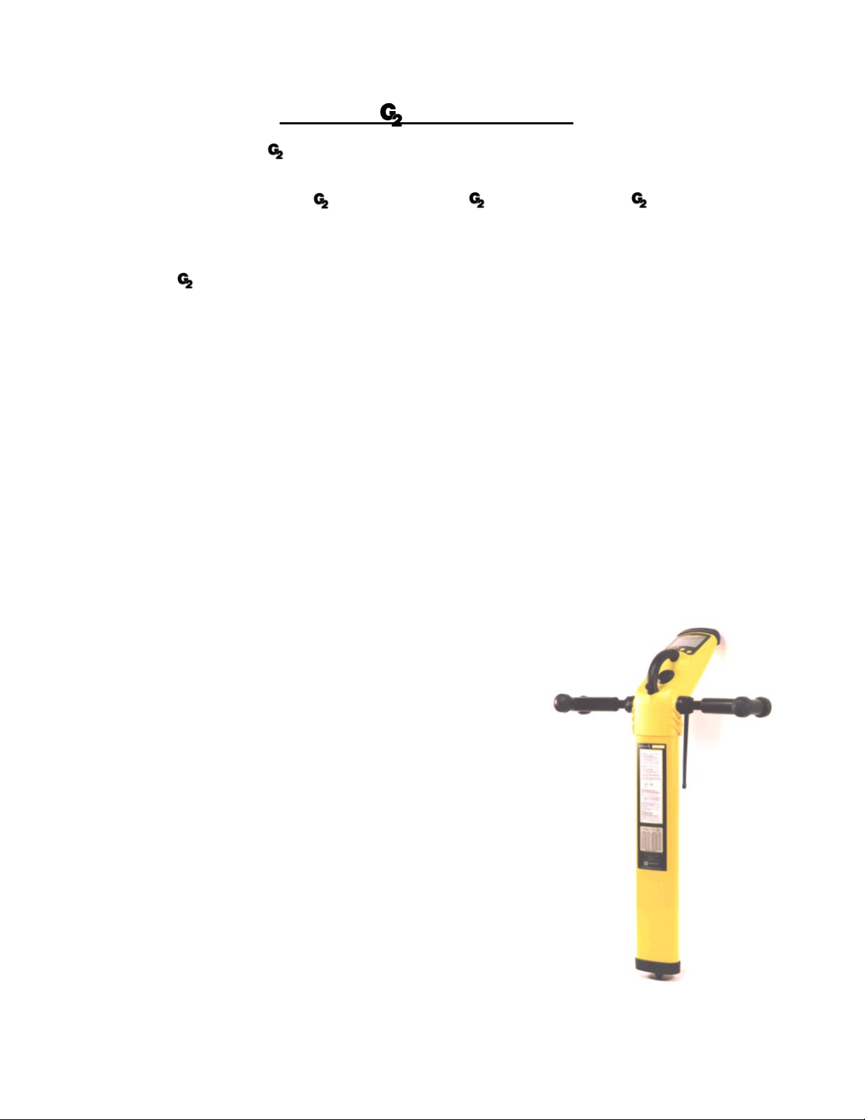
Receiver
The DrillTrack Receiver has been developed with the needs of the operator as the main priority.
Providing essential information automatically makes the equipment very easy to use and allows the operator to
work with confidence.
Once drilling has started the operation is fully automatic and the large LCD shows the operator information
about the drillhead.
The Receiver LCD provides automatic walkover positioning of the drillhead.
Four arrows automatically direct the operator left/right and forward/backward.
When all four arrows are displayed the depth automatically appears on the screen and can be stored in the
integral Borelog.
The display also provides the operator with a Drill Heading (compass), Tilt angle (Inclination), Roll Position
(clock) and in the Manual Mode a Signal Strength reading (if selected in the user Setup).
Feature highlights include:
- Integral Borelogger
- Automatic tracking arrows that indicate Go... Left/Right/Forward/Backward.
- Drill head direction compass indicator.
- Interference rejection technology.
- Filtered rejection of standard line locator frequencies.
- DataSonde frequency scanner
- No mis-locates due to ‘ghost signals’.
- No confusion caused by +/- locates.
- Down hole frequency change to overcome localised interference.
- Tilt angle compensated locate position and depth measurements.
- Automatic Depth readout.
- Metric or Imperial readout selection.
- Continuous display of Tilt angle and Roll position.
- Tilt angle in % of Grade or degrees.
- Display Backlight.
- Comfortable working height to minimize fatigue.
1-1
DrillTrack System Overview
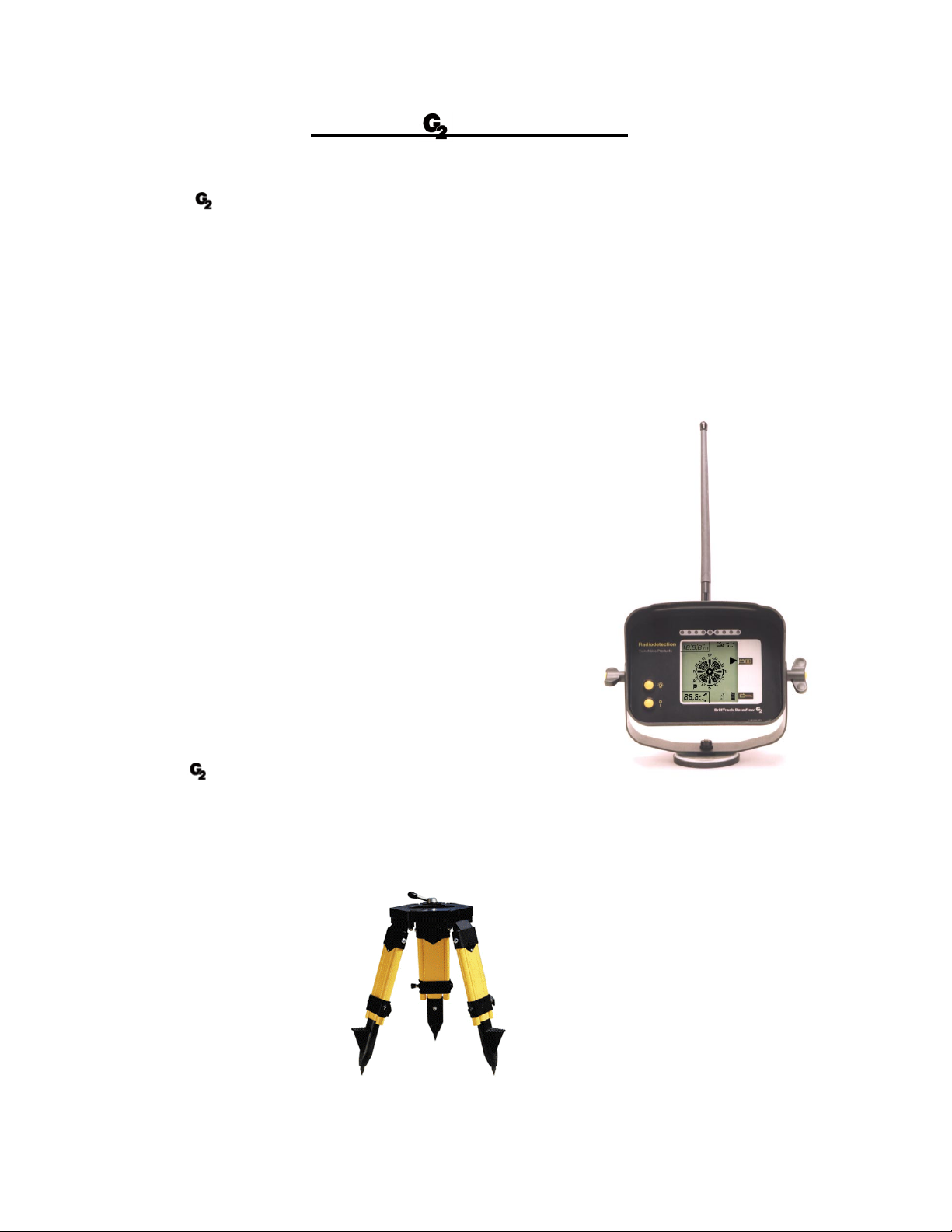
DataView
The DrillTrack DataView has been developed with the needs of the Drilling machine operator as the main
priority.
With its magnetic base the portable DataView provides essential information that allows the Drilling machine
operator to work with confidence.
Once drilling has started the operation is fully automatic and the large LCD shows the Drilling machine
operator all the relevant data transmitted from the DataSonde to the Receiver which is then relayed to the
DataView in real time.
The information includes, Tilt angle (Inclination), Roll position (clock), Depth, Remote Left/Right steering and
Alarm Conditions.
Feature highlights include:
- Fully automatic with no operational buttons or controls.
- Depth readout upon request.
- Automatic selection of Metric or Imperial readout.
- Continuous display of Tilt angle and Roll position in real time.
- Tilt angle in % of Grade or degrees.
- Continuous display of DataSonde Temperature and
DataSonde Battery status.
- Remote Left/Right steering.
- Sounder alert
- Display Backlight.
Tripod
The DrillTrack Tripod has been designed to provide the user a non
walkover remote steering system.
When the Receiver is placed in the Tripod, facing the HDD machine , the Receiver and DataView become a
non walkover remote steering system.
The LED display on the DataView provides the drilling machine operator the left/right steering information of
the drilling process.
1-2
DrillTrack System Overview
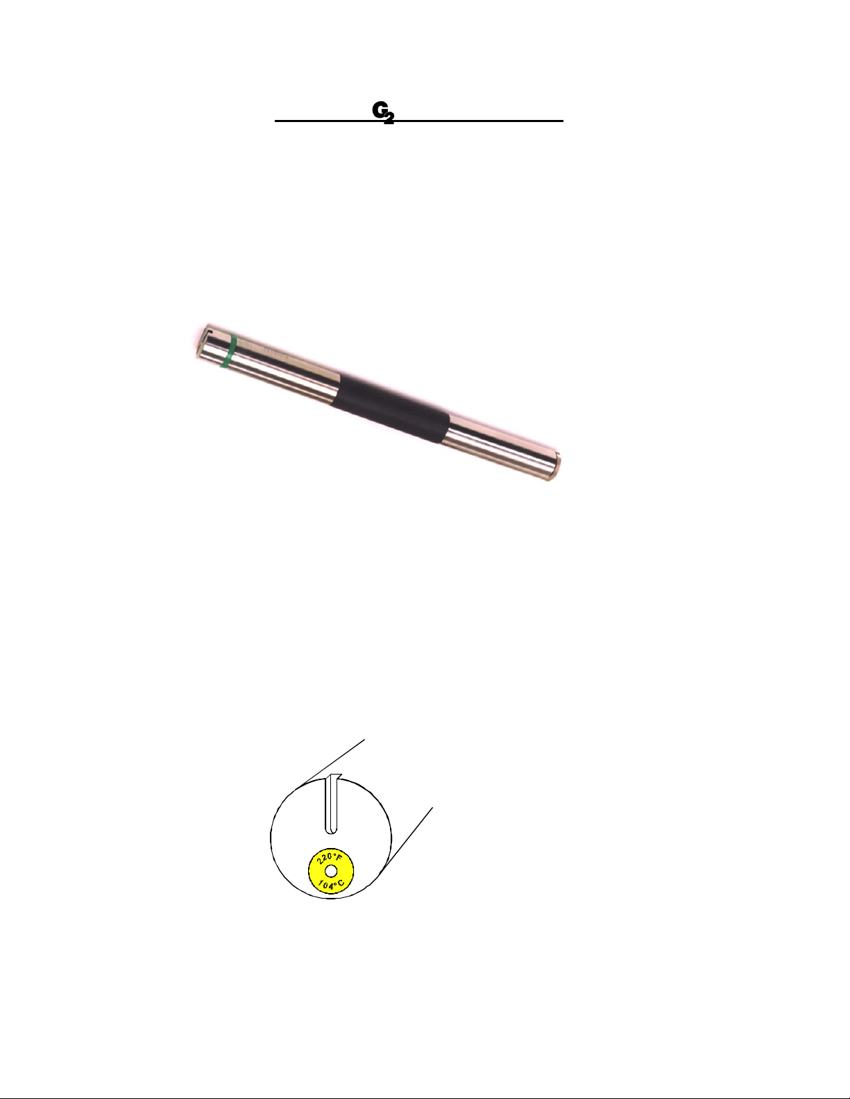
DataSonde
The DataSonde is installed in the drillhead/DataSonde housing.
To ensure optimum DataSonde performance and protection, the DataSonde should be securely fitted in the
drillhead/DataSonde housing. DataSondes may need minor modifications to ensure a secure fit.
O-rings or electrical tape are an acceptable means.
All Radiodetection DataSondes are constructed in three main sections.
Electronics
Antenna
Battery Compartment
Battery compartment
Batteries are inserted in the back end of the DataSonde with the positive end first. Always use ALKALINE
batteries.
Antenna
The antenna is positioned in the middle section of the DataSonde. The slots in the drillhead/DataSond e
housing should be positioned over the antenna section of the DataSonde to allow the electro magnetic field
from the DataSonde to be generated without any restriction.
Wrong positioning or length of the slots will effect the signal range and battery life of the DataSonde.
Electronics
The sensors for measuring the Roll Position (clock), the Tilt angle (Inclination), the DataSonde Temperature
and the Battery Status are located in the electronics section of the DataSonde.
The slot in the front end of the DataSonde fits the anti-roll pin in the drillhead/DataSonde housing
to stop the DataSonde from rotating inside the drillhead DataSon de housing, when drillin g.
1-3
DrillTrack Function keys
Receiver.
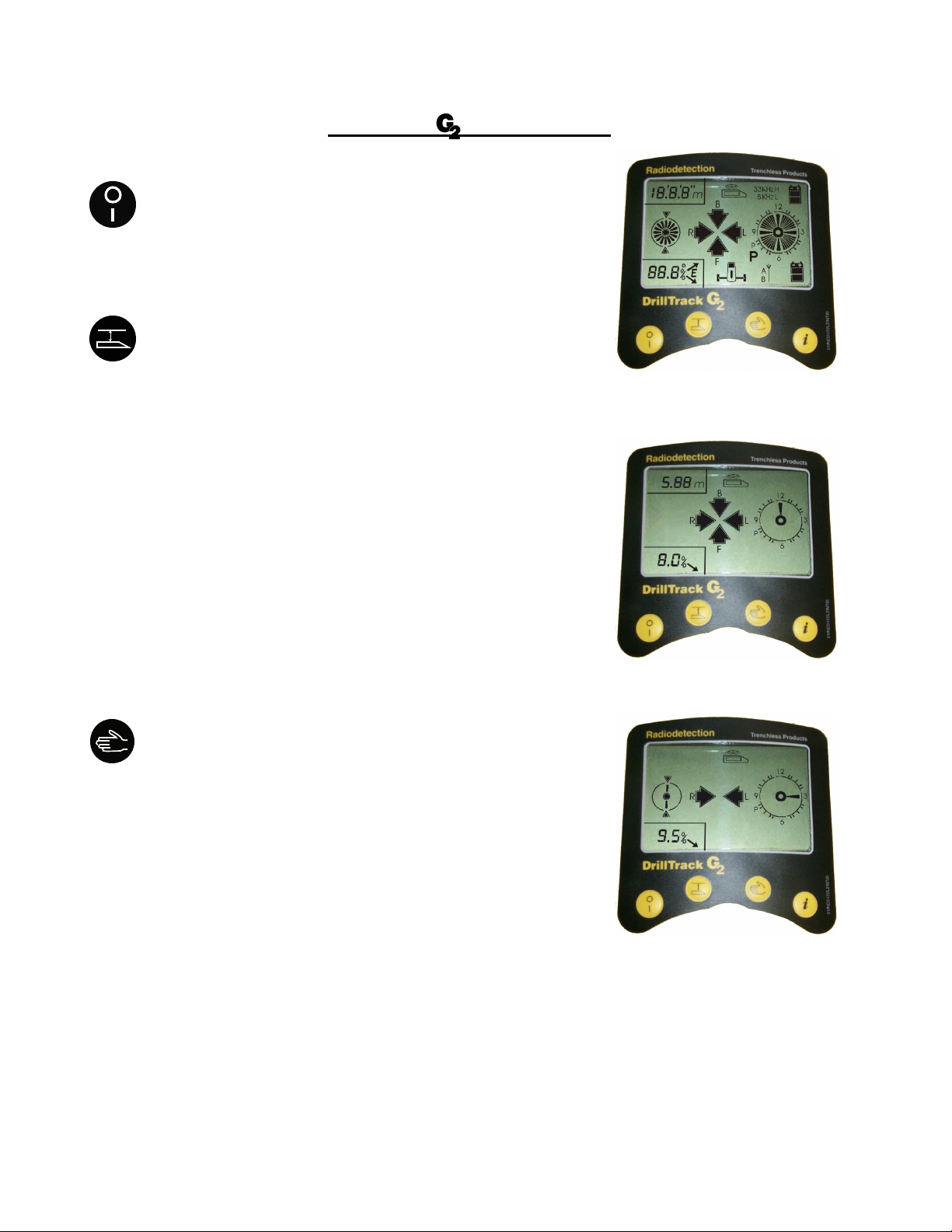
On/Off Key
Press to switch the Receiver On or Off
Depth Key
Press to transfer the current DataSonde depth to
the DataView. An audio beep will confirm the depth
transfer to the DataView.
Manual Depth
When in the “Four Arrows Locate” screen, within
a radius of about 50 cm (20 in) of the actual locate point,
press to get a depth indication readout on the screen.
Borelogger Operation
Press and hold to enter the BORELOGGER Mode.
(for Borelogger instructions see page 4-1)
Calibrate Operation
While the Receiver is turned off, press and hold the
depth key, then press the On/Off key to switch the
unit on and enter the DEPTH CALIBRATION Mode.
(for depth calibration instructions see page 3-5)
Manual Key
Press to toggle between the “Steering” (compass) and
the “Four Arrows Locate” screen in the AUTOMATIC Mode.
Press and hold to enter the REMOTE STEERING Mode.
In the REMOTE STEERING Mode, press and hold to enter
the MANUAL Mode.
To exit from either REMOTE STEERING or MANUAL Mode,
press the Manual key to return to AUTOMATIC Mode.
Backlight Operation
While the Receiver is turned off, press and hold the
Manual key, then press the On/Off key to switch the
unit on and illuminate the backlight.
2-1
DrillTrack Function keys
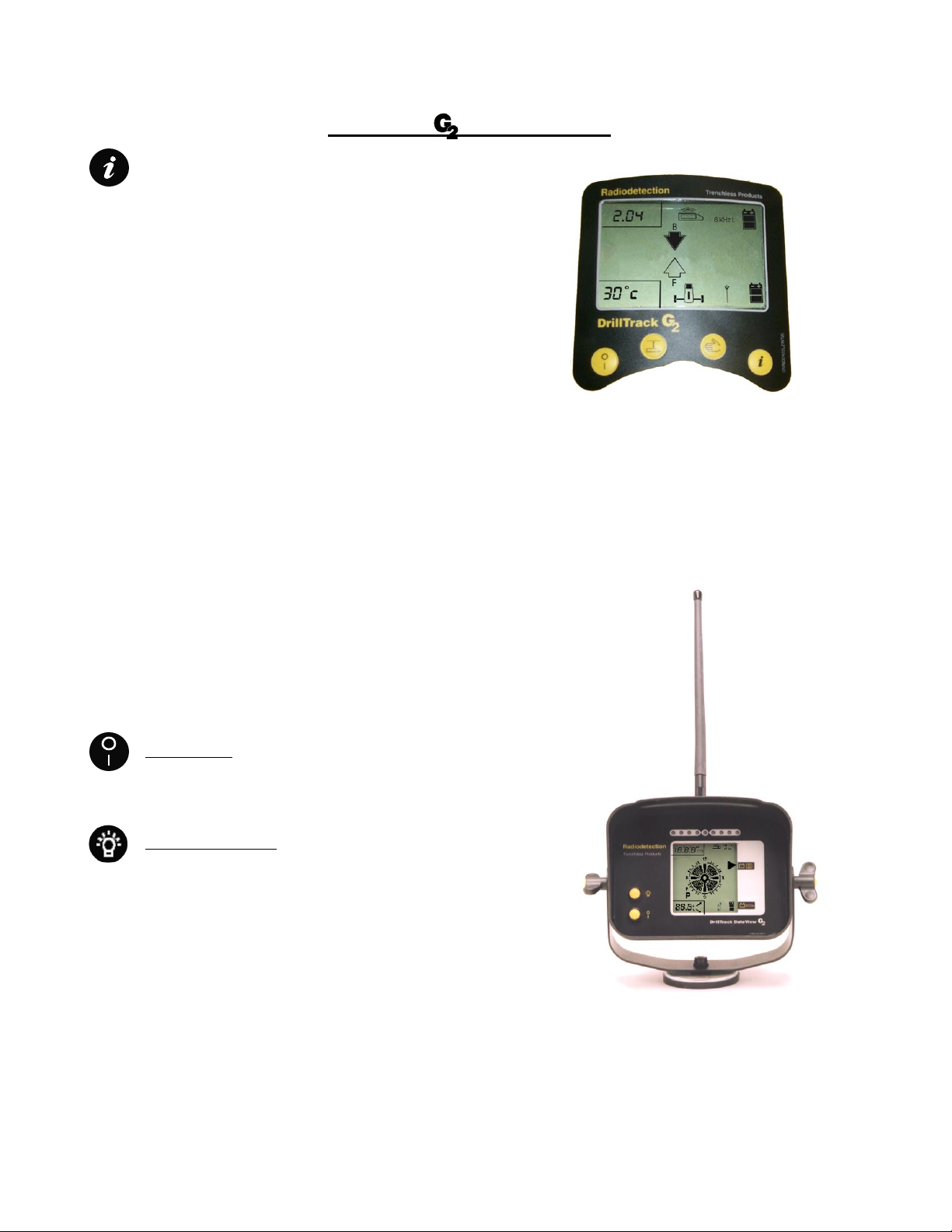
Information key
Press to display the information screen.
The information screen displays:
- Selected DataSonde operating frequency;
- DataSonde battery status;
- DataSonde operating temperature;
- Receiver software version;
- Receiver battery status;
- User selected Locate Orientation (F or B).
Setup Mode
While the Receiver is turned off press and hold the
Information key then press the On / Off key to switch
the unit on and enter into the SETUP Mode.
(for Setup Mode instructions see page 3-1)
DataView
On / Off key
Press to switch the DataView On or Off
Backlight On / Off
Press to illuminate the DataView backlight.
The backlight will only illuminate when data is being displayed.
2-2

DrillTrack Operating Instructions
Before starting
Fit new alkaline batteries in the DataSonde observing the correct polarity. The Receiver must be fitted with 6
x 1.5V’C’ size alkaline (LR14) or 3 Rechargeable Battery Packs. For the correct battery type refer to the
Technical Specification section on DataSondes in this user manual .
Switch the DataView on and using the magnetic mounts, place it on the Drilling machine in a comfortable
viewing position for the Drilling machine operator.
Lock and secure the receiver antenna outriggers into position.
Setup the DrillTrack Receiver.
The Receiver Setup Menu allows the user to initially set the Receiver to the required measurements.
While the Receiver is turned off, press and hold the key, then press the key to switch the unit on and
enter the Setup Menu.
Using the and the key to select the required option, and press the key to confirm the selected
option and to go to the next screen.
Repeat this procedure for all the Setup Menu screens.
The following screens with options will be displayed in the Setup Menu:
- Depth measurement in Metric or Imperial.
- Tilt angle measurement in Percentage of grade or Degrees.
- DataSonde Temperature measurement in Celsius or Fahrenheit.
- Numeric signal strength Activated or Deactivated.
- Selection of type and frequency of DataSonde
- Locate orientation.
- Borelogger System Activated or Deactivated.
- DataView selection
3-1

DrillTrack Operating Instructions
Depth Measurement Units
Tilt Measurement Units
DataSonde Temperature
Signal strength
3-2

DrillTrack Operating Instructions
Frequency and type of DataSonde
Locate orientation
DataView
Borelogger
3-3

DrillTrack Operating Instructions
Calibration of the DrillTrack Receiver
Fit new alkaline batteries in the DataSonde, observing the correct polarity. Fit the DataSonde securely in the
drillhead/DataSonde housing. To ensure a tight fit, electrical tape or O-rings could be used.
Press and hold the key,
and turn the Receiver on,
by pressing the key.
Release the key when “CAL”
appears on the Receiver display.
Note:
If the Receiver is set to automatic DataSonde
selection in the setup mode, the integral scanner will first
select the type and frequency of the DataSonde before
the Receiver will commence the calibration.
Position the drillhead/DataSonde hous ing at exactly
1metre (39 in) from the Receiver blade at a 90º angle.
m
1
)
”
3
9
(
1m (39”)
Move the Receiver in all four directions,
keeping the distance of 1 metre (39 in),
until all four locate arrows appear on the screen.
To calibrate the Receiver press the key.
A double beep and a 1m (39“) readout on the display
confirms that calibration is complete.
To store the calibration in the Receivers memory, press the key.
To exit the calibration mode press the key.
If a dual frequency DataSonde is used, the calibration process should be repeated for
the other frequency.
Note:
Providing that the Receiver, DataSonde and drillhead/DataSonde housing have not been changed, calibration
should only need to be carried out once. However, it is recommended that a depth check is carried out prior to
every new bore.
3-4

DrillTrack Operating Instructions
Receiver Operation
Locate the Drillhead/DataSonde housing by moving the Receiver in the direction indicated by the four arrows
on the LCD. When all four arrows appear on the screen, you are directly above the Drillhead/DataSonde
housing and the depth will be displayed automatically.
To toggle between the “Two Arrows Steering” screen and the “Four Arrows Locate” screen, press the Manual
key.
Moving forward, away from the Drillhead/DataSonde housing, the screen will automatically change from the
“Four Arrows Locate” to the “Two Arrows Steering” screen.
When behind the Drillhead/DataSonde housing and moving forward towards the Drillhead/DataSonde housing,
the screen will automatically change from the “Two Arrows Steering” screen to the “Four Arrows Locate”
screen.
3-5

DrillTrack Operating Instructions
3-6

DrillTrack Operating Instructions
3-7

Steering
DrillTrack Operating Instructions
3-8

DrillTrack Operating Instructions
3-9

DrillTrack Operating Instructions
Tilt angle Compensation
Locate position and depth measurement with a conventional guiding system.
Depth
Tilt angle compensated locate position and depth measurement of the Receiver
Depth
3-10

DrillTrack Operating Instructions
DataView Operation
The DataView is mounted on the Drilling
machine using its magnetic base.
The DataView can be powered by either four C-size alkaline
batteries or can be connected directly to the 12V power supply
of the drilling machine.
The DataView LCD provides the Drilling machine operator all the
relevant data transmitted from the DataSonde to the Receiver
which is then relayed to the DataView in real time. The information will
include, Tilt angle (inclin ation), Roll position(clock), Depth (upon
request), DataSonde operating Temperature and alarm conditions.
DataView alarms are as follows:
- DataSonde Temperature alarms. (see page 3-15)
- DataSonde Battery LOW alarm.
- DataView Battery LOW alarm.
Remote steering operation
A row of nine LEDS gives the Drilling machine operator left/right remote steering information. This information
allows the Drillin g machine operator to steer the drillhead Left/Right towards the Receiver and past the
Receiver.
Operating in the remote steering mode, the Receiver should be placed in the Tripod, facing the Drilling
machine.
Please note that electrostatic discharges to the DataView may cause temporary loss or corruption of the LCD
or LED display. To restore the display, switch the unit off and then back on again.
3-11

DrillTrack Operating Instructions
3-12

DrillTrack Operating Instructions
3-13

DrillTrack Operating Instructions
DataSonde Powersave Modes
All Radiodetection DataSondes have two powersave modes for reducing battery consumption while the
DataSonde is not operating.
Standby Mode
A DataSonde will enter in the Standby Mode during drilling operation when there is no rotation for ten minutes.
In the Standby Mode the DataSonde will send a pulse signal every ten seconds.
Starting rotation will make the DataSonde to return to full operation and exit the Standby Mode.
In the Standby Mode the battery consumption will be reduced to 50%.
Park Mode
In the case that a Directional Drilling operation will be stopped for a certain period of time, at a lunch break or
at the end of a working day, the DataSonde can be put into a Park Mode to save 65% of the battery
consumption. To enter in the Park Mode the DataSonde has to be set to the “P” rotate position. This is the
position on the clock between eight and nine.
After leaving the DataSonde in this rotate position for ten minutes, on the Receiver display a large “P” will be
displayed. The DataSonde will stop sending data and locate signal and will enter the Park Mode.
Starting rotation will make the DataSonde to return to full operation and exit the Park Mode.
Dual Frequency DataSonde Change Method
The Dual Frequency DataSondes allow the user to change between low and high frequency during drilling
operation, using a coded rotation sequence. In most cases the low frequency is the most reliable frequency to
use. It will give a more precise locate position and a more accurate depth than other available operating
frequencies.
Before starting the change over of the frequency, it is needed to pull back to the last position where all
DataSonde information was available.
The Dual Frequency DataSonde will change frequency using the 3 step coded rotation sequence outlined below:
1 - Set to Park, wait for “P”
and for the Receiver and DataView to beep twice.
2 - Rotate to 3 o’clock, wait for overtilt indicated
and for the Receiver and DataView to beep twice.
3 - Rotate again to 3 o’clock,
wait for the Receiver and DataView to beep twice.
As the Dual Frequency DataSonde changes frequency the Receiver frequency will also change automatically.
All relevant information from the DataSonde will then be displayed on the screen.
The Receiver frequency can also be manually set (in the setup menu).
Confirm operation has changed to the new frequency by pressing the key on the Receiver, which
indicates current DataSonde frequency.
Note
When using the Dual Frequency DataSonde, it is important to calibrate the Receiver in both low and high
frequencies.
3-14

DrillTrack Operating Instructions
DataSonde Temperature Alarms
A DataSonde temperature alarm will occur at a temperature of 40oC (104oF).
The Receiver beeps and will automatically display the information screen for 15 seconds. The DataView
sounder will beep and the LCD will flash the high temperature. Such alarm indication will occur with every 5oC
of temperature increase.
When the DataSonde temperature reaches 75°C (167oF) both the Receiver and DataView will display “HI” and
NO Tilt angle or Roll position data will be displayed until the DataSonde temperature falls below 40°C (104oF).
Exceeding of the DataSonde its maximum temperature will permanently damage the DataSonde and will void
any warranty.
The Temperature of the DataSonde is continuously displayed on the DataVie w at the directional drilling
machine. The DataSonde temperature is also displayed on the information screen of the Receiver.
A temperature overheat indicator is located at the front of the electronics endcover and indicates if the
DataSonde has exceed its maximum operating temperature of 104°C (220o F)
temperature has not exceeded its maximum.
temperature has exceeded its maximum.
The DataSonde can also be internally interrogated by a Radiodetection authorized service repair center, to
verify the exact high temperature reached.
3-15

DrillTrack BoreLogger Instructions
The Borelogger can be activated or deactivated in the set-up menu (see page 3-1)
To activate the Borelogger access the set-up mode and set the BORELOG option to ON.
To enter Borelog Mode press and hold the key. A list of functions for the logging will appear:
GO, DEL, END, UP
Scroll through using the or key, press key to confirm selection.
To start a log, set the log to GO.
When in the “Four-Arrows Locate” screen with depth displayed. Press the key to transmit the
depth to the Data View. The screen will then display “LOG”, press key again within 5 seconds to
confirm. The display changes to a new screen, an audible beep confirms the action of logging the
data, showing “LOG” and the stored rod number
To add a simulated locate point, in the “Two Arrow Steering” screen press the key, the display will
show ADD and LOG with a rod number, press key again to confirm the addition of the simulated
locate point.
To delete one log back, hold down the key to enter the Borelog Mode.
Select DEL and press INFO to show the last stored rodnumber. Press the key within 5 seconds to
delete the last log. A double beep will confirm deletion. When finished deleitng, press and hold
key and select GO to return to logging data.
When finished with logging, it is important that the log is manually ended. Do this by entering into the
Borelog Mode and select END. Upon completion of the Borelog date and time will be stored.
To upload the Borelog data, enter the Borelog Mode and select UP and press key to activate the
data transfer. A rotating clock will appear to confirm that the unit is waiting to upload the log to the PC.
After uploading is completed, turn off the Receiver.
4-1

Tips and Tricks
Troubleshooting Guide.
When reporting any problem to your Radiodetection dealer it is important to quote the following:
- Unit Serial Number.
- Software Revision Number.
Software Revision Number of the Receiver is displayed on the LCD during switch-on or by pressing the
Information key.
Software Revision Number of the DataView is displayed on the LCD during switch-on.
Problem 1: The Receiver or DataView will not power on.
1- Replace all batteries, using either Alkaline batteries or the rechargeable battery packs.
2- Check the condition of the battery compartment. Make sure all batteries are fitted correctly and are making
good contact, keep battery contact points clean.
Problem 2: No Tilt angle/Roll Data on the Receiver display.
1- Check if DataSonde icon on the receiver LCD is displayed continuously or is flashing. A flashing icon
indicates no information is received from the DataSonde.
2- If there is no Tilt angle/Roll data on the screen, but the DataSonde can be located, check the receiver
Setup.
3- Check DataSonde if no data has been received at all. If data has been received during drilling, but is no
longer available, go to Problem 6: Data lost.
Problem 3: No Radio-link between Receiver and DataView.
1- Check if data can be regained by moving the DataView closer to the Receiver.
2- Make sure both radio-link antennas are fitted and are making good contact.
3- Check for any radio transmission towers or GSM repeaters that can cause interference.
5-1

Tips and Tricks
Problem 4: Incorrect Depth readings.
1- Calibrate the Receiver to the DataSonde (while in the drillhead/DataSonde housing).
2- Check the DataSonde operation in the drillhead/DataSonde housing before going underground.
3- Check the slotting arrangements in the drillhead/DataSonde housing. The slots should be approximately
150% of the length of the DataSonde antenna section, and line up longitudinally along the
drillhead/DataSonde housing, directly above the DataSonde. A minimum of four slots equally spaced
around the drillhead/DataSonde hous ing is required. Wrong length and or position of the slots can greatly
affect the DataSonde signal range and battery life.
4- Check if the Receiver is set to Metric or Imperial units.
5- Use a Radiodetection locator to check for interference from buried utilities.
Problem 5: Receiver will not calibrate.
1- Move the Receiver and drillhead/DataSonde hous ing with DataSonde to a more interference free location
and try again.
2- Make sure that the calibration distance between Receiver and center of the drillhead/DataSonde housing is
exactly one metre.
3- Check the slotting arrangements in the drillhead/DataSonde housing.
Problem 6: Data lost.
1- Check that the drillhead/DataSonde housing has not exceeded the DataSonde signal range.
2- Check if the DataSonde data can be regained by pulling back to the last locate point.
3- Excessive shock/vibration can cause the DataSonde to temporarily shut down.
Wait ten minutes. Make sure the DataSonde has been adequately protected inside the
drillhead/DataSonde housing against shock/vibration.
4- High DataSonde temperature may have caused lost of signal. Check temperature overheat indicator
on the front of the DataSonde.
5- Replace the DataSonde batteries.
5-2

Angle conversion table
Inclination cm/m ft/10ft
o
2.9
o
5.7
o
8.5
Tips and Tricks
5% 5 0.5
10% 10 1.0
15% 15 1.5
11.3
14.0
16.7
19.3
21.8
24.2
26.6
28.8
31.0
33.0
35.0
o
20% 20 2.0
o
25% 25 2.5
o
30% 30 3.0
o
35% 35 3.5
o
40% 40 4.0
o
45% 45 4.5
o
50% 50 5.0
o
55% 55 5.5
o
60% 60 6.0
o
65% 65 6.5
o
70% 70 7.0
36.9
38.7
40.4
42.0
43.5
45.0
o
75% 75 7.5
o
80% 80 8.0
o
85% 85 8.5
o
90% 90 9.0
o
95% 95 9.5
o
100% 100 10.0
5-3

Technical Specifications
Receiver:
Physical
Construction High impact thermoplastic weatherproof to NEMA 3R and IP54 (base to top of main
housing to IP67).
Ruggedness Withstands 1 m (3 ft) drops onto concrete.
Dimensions 100 x 65 x 30 cm (39.3 x 25.5 x 12 in.).
Shipping Box Size 123 x 39 x 27 cm (48.4 x 15.4 x 10.6 in.).
Weight 4.5 kg (9.9 lb).
Shipping Weight 7 kg (15.4 lb).
Operating
Frequencies 8.4kHz and 33.6kHz or 8.192kHz and 32.768khz
Locate Accuracy ±5% of DataSonde depth.
Depth Accuracy ±5% to 10 m (32 ft) reducing to ±10% to 20 m (65 ft).
Depth Range 0.2m - 20 m (3 - 65 ft).
Remote Steering
Range DataSonde depth at 3-5m (9-16ft) = Range 25m (82ft)
DataSonde depth at 5-25m (16-82ft) = Range <25m (82ft) reducing linearly with
DataSonde depth
Visual Indication Liquid Crystal Display indicating the following on various screens:
DataSonde Roll DataSonde Pitch
DataSonde Depth Left/Right Arrows
Forward/Backward Arrows Compass (to DataSonde)
Operating Frequency Receiver Battery Status
DataSonde Temperature DataSonde Battery Status
Signal Strength (Manual Mode)
Audio Indication Audio signal output through waterproof sounder.
Search Antennas 1 x vertical, board mounted. 1 x horizontal transverse, board mounted.
2 x horizontal in-line, 60 cm apart, outrigger mounted.
Gain Control Automatic gain control.
Batteries 6 x LR14 (C) 1.5 V alkaline.
12 hours life, nominal @ 20°C (68°F) intermittent use.
8 hours life, with Backlight (25% On:Off duty cycle).
Operating
Temperature Range -20°C to +50°C (-4°F to +122°F).
Compatibility Complete Range of Radiodetection DataSondes.
6-1

Technical Specifications
DataView
Backlight Switchab le Backlight
LEDs LEDs display left/right indication when set in Remote mode.
Batteries 4 x ‘C’ cells
Visual Indication Liquid Crystal display indication the following on various screens
DataSonde Roll DataSonde Pitch
DataSonde Depth DataSonde Battery Status
DataSonde Temperature DataView Battery Status
Depth display available when information transferred from Receiver.
Range 500m line of sight.
Borelogger Storage capacity >2000 data points, rolling store
Data storage Non volatile memory, > 10 years retention
Real time clock Set to GMT
Clock battery backup Lithium battery, >10 years
System compatibility Vermeer Atlas Boreplanner
Radiodetection DrillTrack Bore Log
TM
6-2

Technical Specifications
DataSonde
Short Range DataSonde (SDS)
Approximate Signal range 4m (12 ft)
Battery life 10 hrs
Size 25,4 x 203 mm (1 x 8 in)
Medium Range DataSonde (MDS Black)
Approximate Signal range 10m (33 ft)
Battery life 20 hrs
Size 32 x 380 mm (1.3 x 15 in)
Long Range DataSonde (LDS Red)
Approximate Signal range 15m (50 ft)
Battery life 12 hrs
Size 32 x 380 mm (1.3 x 15 in)
Medium Range Dual Frequency DataSonde (MDF Yellow)
Approximate Signal range 10m (33 ft)
Battery life 20 hrs
Size 32 x 380 mm (1.3 x 15 in)
Long Range Dual Frequency DataSonde (LDF Purple)
Approximate Signal range 15m (50 ft)
Battery life 12 hrs
Size 32 x 380 mm (1.3 x 15 in)
G2 Medium Range Dual Frequency DataSonde (G2M Green)
Approximate Signal range 10m (33 ft)
Battery life 20 hrs
Size 32 x 380 mm (1.3 x 15 in)
G2 Long Range Dual Frequency DataSonde (G2LOrange)
Approximate Signal range 15m (50 ft)
Battery life 12 hrs
Size 32 x 380 mm (1.3 x 15 in)
6-3

Warranty
Subject to the conditions set out below Radiodetection Limited warrants to the original purchaser, that the
Radiodetection equipment will correspond with their specification at the time of delivery and will be free from
defects in material and workmanship for the periods specified below as from the date of delivery.
Description of warranty rights.
From the date of purchase through the applicable warranty period, Radiodetection will repair or replace free of
charge any warranted item which is found to be defective. All warranty inspections and warranty repairs must
be performed by
Radiodetection Ltd
Western Drive
Bristol
BS14 0AZ
United Kingdom
The implied warranties of merchantability and fitness for a particular purpose are hereby disclaimed.
DrillTrack Receiver 12 months
DrillTrack DataView 12 months
Short Range DataSonde (SDS) 3 months
Medium Range DataSonde (MDS Black) 12 months
Long Range DataSonde (LDS Red) 12 months
Medium Range Dual Frequency DataSonde (MDF Yellow) 12 months
Long Range Dual Frequency DataSonde (LDF Purple) 12 months
Medium Range Dual Frequency DataSonde (G2M Green) 12 months
Long Range Dual Frequency DataSonde (G2L Orange) 12 months
DrillTrack Accessories 12 months
Radiodetection Ltd
Western Drive
Bristol BS14 OAZ, UK
Tel: +44 (0) 117 976 7776
Fax: +44 (0) 117 976 7775
email:sales.uk@radiodetection.com
http://www.radiodetection.com
Radiodetection products are under continuous
development and are subject to change without
notice
All rights reserved 90/UGO50US/3


Registration Card
With this registration card you can register your DrillTrack system at Radiodetection Ltd.
Registration entitles you to free software updates and product information.
Company Name: ..........................................................................................
Address: ..........................................................................................
..........................................................................................
..........................................................................................
Phone: ......................................... Fax: ...................................
Date of purchase: ..........................................................................................
DrillTrack Receiver Serial Nr. ................................................
DrillTrack DataView Serial Nr. ................................................
Short Range DataSonde (SDS) Serial Nr. ................................................
Serial Nr. ................................................
Medium Range DataSonde (MDS Black) Serial Nr. ................................................
Serial Nr. ................................................
Long Range DataSonde (LDS Red) Serial Nr. ...............................................
Serial Nr. ...............................................
Medium Range Dual Frequency DataSonde (MDF Yellow) Serial Nr. ...............................................
Serial Nr. ...............................................
Long Range Dual Frequency DataSonde (LDF Purple) Serial Nr. ...............................................
Serial Nr. ...................................................
G2 Medium Range Dual Frequency DataSonde (G2M Green) Serial Nr. ...............................................
Serial Nr. ...............................................
G2 Long Range Dual Frequency DataSonde (G2L Orange) Serial Nr. ...............................................
Serial Nr. ...................................................
Please mail or fax this card to: Radiodetection Ltd.
Western Drive
Bristol BS14 0AZ
United Kingdom
Tel: +44 (0)117 9767776
Fax: +44 (0)117 9767775
 Loading...