

Page 1

PDL-4 A.C.ID-M
System (with GPS)
User Guide
Rev 1 10/2002
Page 2

PDL-4 A.C.ID-M System (with GPS) User Guide
Page 3

PDL-4 A.C.ID-M System (with GPS) User Guide
TABLE OF CONTENTS
SAFETY NOTES ..................................................................................................................................... 5
VECTORBAR 20–COMPLIANCE STATEMENTS ............................................................................................. 5
INTRODUCTION ..................................................................................................................................... 1
PDL-4 RECEIVER................................................................................................................................. 1
VECTORBAR ........................................................................................................................................ 1
EXTENDED RANGE V ECTORBAR..............................................................................................................1
VECTORBAR 20.................................................................................................................................... 1
SMARTP ROBE-2...................................................................................................................................2
EXTENDED RANGE SMARTPROBE-2......................................................................................................... 2
GLOBAL POSITIONING SYSTEM (GPS)...................................................................................................... 3
PDL-4 RECEIVER FEATURES ................................................................................................................ 3
PEAK/NULL KEY .................................................................................................................................... 3
DEPTH /CURRENT KEY............................................................................................................................3
FREQ./MODE KEY ................................................................................................................................. 3
MENU KEYS......................................................................................................................................... 3
GAIN CONTROL PADDLE......................................................................................................................... 3
SPEAKER SOUNDS................................................................................................................................ 4
PDL-4 ........................................................................................................................................................................................4
GPS...........................................................................................................................................................................................5
BATTERY REPLACEMENT .....................................................................................................................5
PDL-4................................................................................................................................................ 5
VECTORBAR AND EXTENDED RANGE V ECTORBAR .....................................................................................6
VECTORBAR 20.................................................................................................................................... 6
SMARTP ROBE-2 & EXTENDED RANGE SMARTPROBE-2..............................................................................7
PDL-4 OPERATION................................................................................................................................ 7
POWER ON/OFF ................................................................................................................................... 7
ENABLING GPS.................................................................................................................................... 8
GPS COLD S TART ................................................................................................................................8
DISPLAY FIX......................................................................................................................................... 9
CABLE LOCATE MODE............................................................................................................................ 9
MENUS................................................................................................................................................ 9
System Menu..........................................................................................................................................................................9
User Preferences Screen................................................................................................................................................10
PDL-4 Information Screen...............................................................................................................................................11
Confirmation Mode ............................................................................................................................................................ 11
Cable Locate........................................................................................................................................................................11
Direct Selection ................................................................................................................................................................... 12
VECTORBAR OPERATION ................................................................................................................... 12
GREEN B UTTON..................................................................................................................................12
GRADUATIONS....................................................................................................................................12
VECTORBAR 20 OPERATION..............................................................................................................12
GREEN B UTTON..................................................................................................................................12
ARM..................................................................................................................................................12
GRADUATIONS....................................................................................................................................13
SMARTPROBE-2 OPERATION.............................................................................................................13
GREEN B UTTON..................................................................................................................................13
DEPTH GRADUATIONS..........................................................................................................................13
TRACING PROCEDURE.......................................................................................................................14
PEAK................................................................................................................................................14
Page 4

PDL-4 A.C.ID-M System (with GPS) User Guide
14
.........................
NULL.................................................................................................................................................
LOCATE PROCEDURE ................................................................................................
CURRENT DIRECTION (CD)...................................................................................................................14
CD - Reset............................................................................................................................................................................14
DEPTH /CURRENT................................................................................................................................15
CONFIRMATION PROCEDURE.............................................................................................................15
LMS-3..............................................................................................................................................15
PTX-3..............................................................................................................................................15
CABLE IDENTIFICATION ...................................................................................................................... 15
VECTORBAR, VECTORBAR 20 OR EXTENDED RANGE V ECTORBAR.............................................................15
SMARTP ROBE-2 OR EXTENDED SMARTPROBE-2.....................................................................................18
LMS-3..............................................................................................................................................18
PTX-3..............................................................................................................................................18
PENETRATION BAR..............................................................................................................................20
Assembly .............................................................................................................................................................................. 20
Operation .............................................................................................................................................................................. 20
Pothole...................................................................................................................................................................................21
Confirmation Other ............................................................................................................................................................ 21
MANUALLY LOGGING DATA ...................................................................................................................21
SYSTEM UTILITIES ..............................................................................................................................21
UPLOAD DATA LOG .............................................................................................................................22
DOWNLOAD SOFTWARE UPGRADE.........................................................................................................23
RESTORE SYSTEM DEFAULTS...............................................................................................................23
SELF-TEST........................................................................................................................................24
GPS USER GUIDELINES ......................................................................................................................25
FLOWCHART SHOWING WHEN GPS DATA IS LOGGED ON LOCATE CONFIRMATION......................26
VECTORBAR 20 TECHNICAL SPECIFICATION ....................................................................................27
Page 4
Page 5

PDL-4 A.C.ID-M System (with GPS) User Guide
Safety Notes
The above Safety Alert Symbol is used throughout this User Guide to highlight critical information. Read
this information carefully and follow any instructions that may be given.
FCC Statement
Radio Interference
Note: Relevant parts of this equipment have been tested and found to comply with the limits for a Class A
digital device, pursuant to part 15 of the FCC rules. These limits are designed to provide reasonable
protection against harmful interference when the equipment is operated in a commercial environment.
This equipment generates, uses, and can radiate radio frequency energy and, if not installed and used in
accordance with the user manual, may cause harmful interference to radio communications. Operation of
this equipment in a residential area is likely to cause harmful interference in which case the user will be
required to correct the interference at his own expense.
Caution: Any changes or modifications made to this product not expressly approved by Radiodetection
Ltd could void the user’s authority to operate the equipment.
VectorBar 20–Compliance statements
USA
The FCC identification number for the VectorBar 20 is K68AA2614.
Caution: Changes or modifications not expressly approved by the manufacturer could void the user’s
authority to operate the product.
If the equipment is used in a manner not specified by Radiodetection, the protection provided by
the equipment may be impaired.
This device complies with part 15 of the FCC Rules. Operation is subject to the following two conditions:
1. This device may not cause harmful interference.
2. This device must accept any interference received, including interference that may cause undesired
operation.
Page 6

PDL-4 A.C.ID-M System (with GPS) User Guide
Warning
The operation of any cable and pipe locator may be affected when used in close proximity
to ferrous materials such as manhole covers and parked cars. Keep a one or two meter
distance from these objects when taking critical measurements such as depth and
current readings. Standing too close to the locator when wearing steel toe-capped boots
may also affect the readings.
Radiodetection is committed to a policy of continual product improvement and development. Therefore,
there may be slight differences between the screen displays on your equipment and those in this manual.
However, the principles of operation will be the same.
Page 6
Page 7
PDL-4 A.C.ID-M System (with GPS) User Guide
Introduction
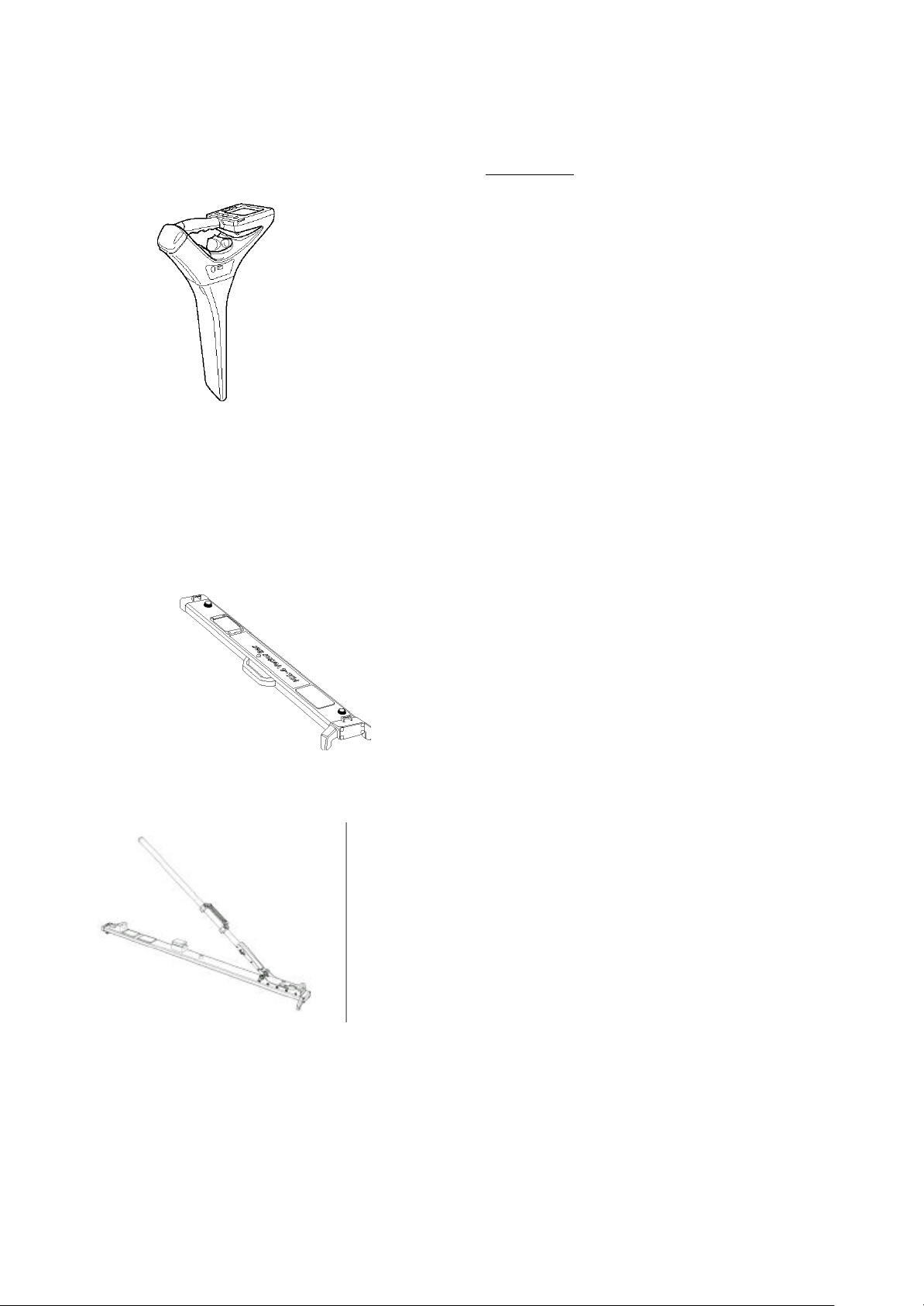
PDL-4 Receiver
The PDL-4 is a portable receiver used for locating
and identifying underground cables.
The Global Positioning System (GPS) fitted to the
receiver enables the position of cables to be
accurately logged and mapped.
When used with the following equipment the PDL-4
will positively identify a cable that emits an A.C.ID-M
(Absolute Current Identification-Multi) signal.
§ VectorBar
§ Extended Range VectorBar
§ VectorBar 20
§ SmartProbe-2
§ Extended Range SmartProbe-2
§ LMS-3 or PTx-3 transmitter
The A.C.ID-M signal is described in the LMS-3
Manual.
Refer to the LMS-3 Manual and PTx-3 User Guides
for transmitter operating instructions.
VectorBar
When placed on the ground over the target cable,
and activated, the VectorBar receives the applied
A.C.ID-M signal and relays A.C.ID-M status
information to the PDL-4 via a short-wave radio link.
Extended Range VectorBar
The extended range VectorBar is tripod mounted and
is used to locate cables that are buried too deep to
be located by the standard VectorBar. Once
assembled the extended range VectorBar operates
in the same way as the standard VectorBar.
VectorBar 20
The VectorBar 20 is used to locate cables that are
buried too deep to be located by the standard
VectorBar. The VectorBar 20 incorporates an
extendable arm to enable cables that have been laid
at a greater depth to be located. The VectorBar 20
can be used with the arm fully stowed or fully
extended. The VectorBar 20 operates in the same
way as the standard VectorBar.
Page 1
Page 8

PDL-4 A.C.ID-M System (with GPS) User Guide
SmartProbe-2
When pushed into the ground in close proximity to
the target cable, and activated, the SmartProbe-2
receives the applied A.C.ID-M signal and relays
A.C.ID-M status information to the PDL-4 via a shortwave radio link.
Extended Range SmartProbe-2
The extended range SmartProbe-2 is used to locate
cables that are buried too deep to be located by the
standard SmartProbe-2. The extended range
SmartProbe-2 operates in the same way as the
standard SmartProbe-2 except for an LED (Light
Emitting Diode) that illuminates when the unit is
activated.
Page 2
Page 9
PDL-4 A.C.ID-M System (with GPS) User Guide
Global Positioning System (GPS)
When the green button on the VectorBar or
SmartProbe 2 is pushed the GPS system will
automatically calculate the position of the receiver.
PDL-4 Receiver Features
On/Off Key
Press and hold for one second to switch the PDL-4
receiver On or Off.
Display Contrast. With the PDL-4 switched off, press
and hold the On/Off key. After a few seconds, the
contrast will automatically cycle through its range.
Release the On/Off key when a satisfactory display
contrast is achieved.
The display contrast can also be set manually.
Refer to the Contrast screen in the System Setup
menu.
Peak/Null key
Toggles between Peak and Null modes, and
indicates the selection on the LCD (Liquid
Crystal Display).
Depth/Current key
Simultaneously displays cable Depth and
Current for five seconds. Depth/Current is not
available in Power mode.
Freq./Mode key
Cycles through the receiver passive and active
operating frequencies.
Menu keys
Pressing a Menu key accesses the Cable Locate
Control menu (Perform CD Reset, Confirmation,
Log Data options).
Note: When using some frequencies not all of
the above options may be available.
Gain Control Paddle
If the signal strength is at maximum or less than
10%, a momentary flick of the control in the
appropriate direction will cause the gain to be
adjusted to give an approximate bar graph
indication of 50%. If the signal strength is below
maximum and greater than 10%, the control will
adjust the gain in 1dB steps with each momentary
flick or by rapid stepping if the control is held when
rotated.
Page 3
Page 10
PDL-4 A.C.ID-M System (with GPS) User Guide
In Direct Selection mode, and when using other
screens requiring selection from a list, rotate the Gain
Control to move the highlight bar up or down. Rotate
the gain control to adjust the contrast when the
Contrast screen is displayed.
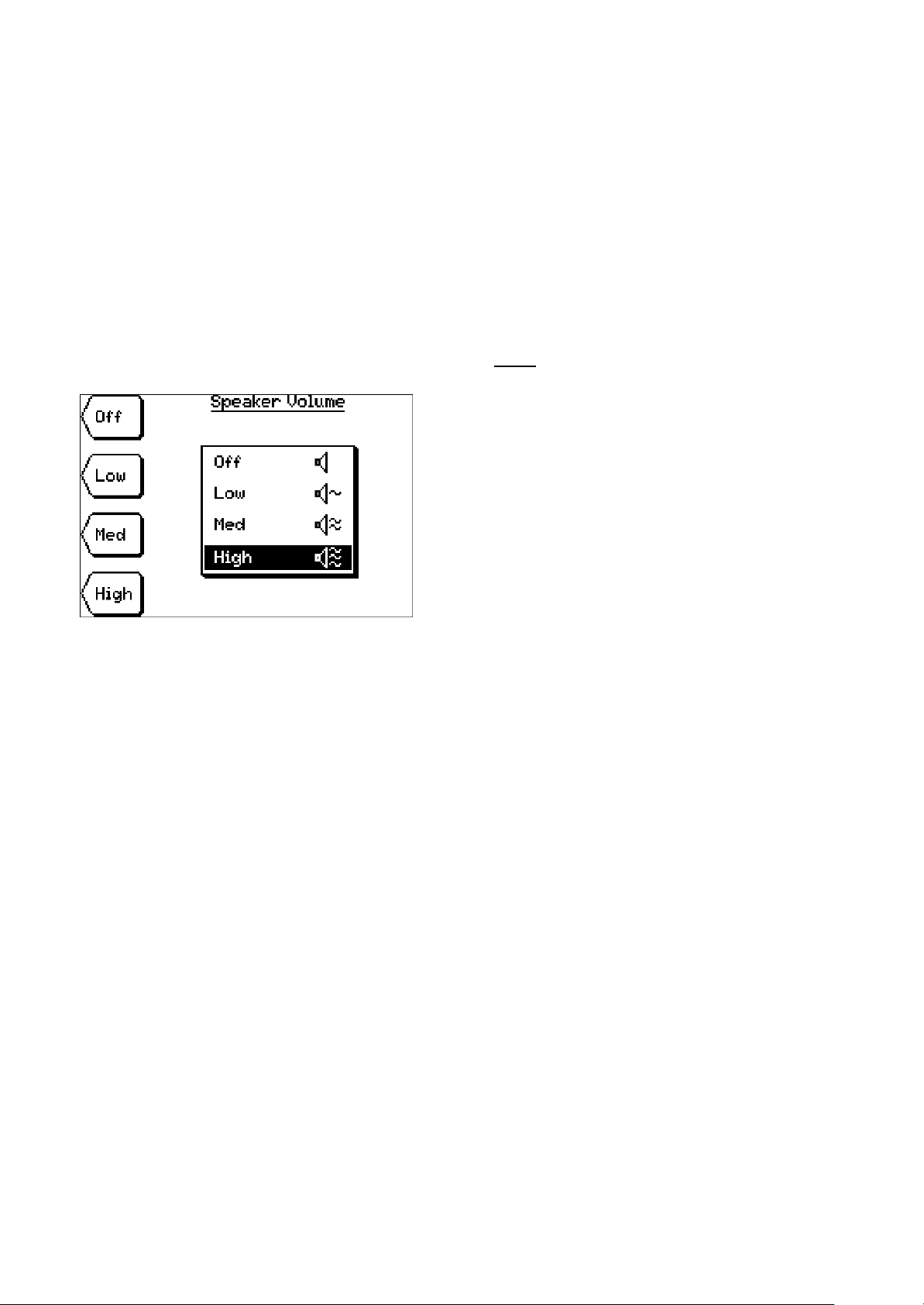
Speaker Sounds
The volume is controllable in four steps: Off, Low,
Medium and High, via the menu system.
PDL-4
The speaker sounds are as follows:
1. At switch-on, the speaker will generate a
continuous tone for 1 second, at the volume
setting last used. If the volume is set to Off, the
tone will still be generated, but at the lowest
audible level.
2. Whenever a key is pressed, the speaker will
generate a confirmation "beep". If the key has a
secondary "press and hold" function a higher
tone beep will also be generated as soon as the
secondary function is initiated.
3. When locating a cable in Null (Left/Right) mode,
the speaker will generate a pulsing tone when
the cable is to the left of the PDL-4, and a
continuous tone when the cable is to the right.
4. When locating a cable in Peak mode, the
speaker volume will increase as the cable is
neared.
5.When locating a cable in Power mode, the
speaker will generate "Signal Sound" - derived
from the signal detected, at amplitude
proportional to the signal amplitude.
6.Whenever the PDL-4 detects an error condition
during a self-test, or at any other time, the
speaker will generate the standard lowfrequency "Error" tone. This will be a short
"beep" if a non-functional key is pressed, or will
be for 2 seconds if an error condition is
detected.
7.Whenever it is necessary to alert the user, the
speaker will generate the standard "Alert" tone.
This will be a repeating cycle of 5 rapid "beeps"
followed by a four-second pause. The Alert
tone will always be generated at the highest
audible level, regardless of the speaker volume
setting.
Page 4
Page 11
PDL-4 A.C.ID-M System (with GPS) User Guide
Conditions resulting in the Alert tone include:
a) The battery becoming almost
exhausted
b) The Inactivity Timer expiring.
When the volume is set to Off, the speaker will still
generate key press confirmation "beeps" and the
"Error" tone - but at the lowest audible level. When
the unit is first switched on, it will select the volume
setting last used.
GPS
• When the location and GPS data have been
acquired and logged, the sounder will generate a
single confirmation “beep”.
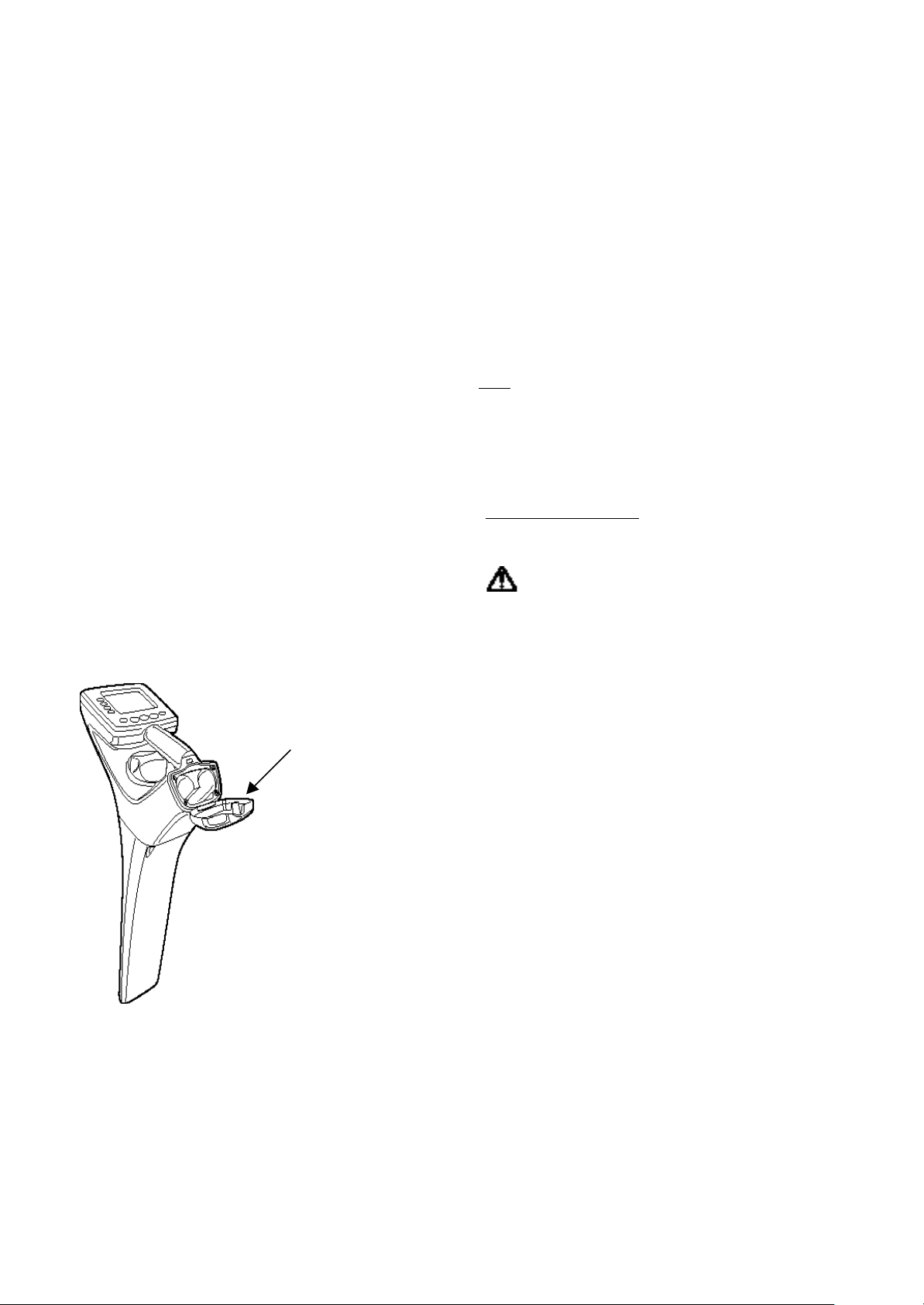
Battery Replacement
PDL-4
Battery housing cover
Warning
Do not mutilate, puncture, or dispose of
batteries by placing them in a fire. The
batteries can burst or explode, releasing
hazardous chemicals.
Discard used batteries in accordance with the
manufacturer’s instructions and your local
regulations.
Two types of battery can be used, either 4 D-cells, or
a single, rechargeable, DR 15AA, Nickel Metal
Hydride (NiMH) type. It is not possible to insert both
types of battery at the same time.
When the LCD shows a low-battery warning it is
necessary to replace the battery.
The battery housing is at the rear of the carrying
handle (see illustration).
Before using the locator, ensure that a charged
battery (or batteries) is installed and correctly fitted.
Note: When using D-cells replace them as a set.
Replacement is the same for both types of
battery.
Page 5
Page 12

PDL-4 A.C.ID-M System (with GPS) User Guide
To replace batteries proceed as follows:
• Release battery-housing cover by means of the
release catch, situated under the carrying handle
• Remove battery or batteries
• Insert new battery or batteries, ensuring correct
installation, as indicated on the label within the
battery housing
• Close battery-housing cover.
VectorBar and Extended Range VectorBar
When activated the VectorBar, or extended range
VectorBar, transmits its battery status to the PDL-4. If
low battery-level is indicated on the PDL-4 display the
batteries should be replaced.
Note: To ensure optimum performance of the
equipment always replace batteries as a set.
There are two battery compartments, located under
separate grey covers, one at each end of the bar. Each
cover is attached by 2 quick-release screws and each
compartment houses 2 D-cells.
To replace the batteries proceed as follows:
• Unscrew the quick-release screws a quarter of a
turn, anti-clockwise
• Remove batteries
• Insert new batteries, ensuring that they are installed
correctly, as indicated on the diagram within the
battery housing
• Replace covers
• Screw in quick-release screws a quarter of a turn
clockwise.
The battery compartment at the green
button end of the VectorBar and extended range
VectorBar also houses an RS232 socket for
software download.
VectorBar 20
When activated, the VectorBar 20 transmits its batterylevel status to the PDL-4. If low battery-level is indicated
on the PDL-4 display the batteries in the VectorBar 20
should be replaced.
Note: To ensure optimum performance of the
VectorBar 20 always replace batteries as a
set.
There are two battery compartments, located under
separate grey covers placed next to each other. Each
cover is attached by 2 quick-release screws, and each
compartment houses 2 D-cell batteries.
Page 6
Page 13

PDL-4 A.C.ID-M System (with GPS) User Guide
To replace the batteries proceed as follows:
• Unscrew the quick-release screws a quarter of a
turn, anti-clockwise
• Remove batteries
• Insert new batteries, ensuring that they are installed
correctly, as indicated on the diagram within the
battery housing
• Replace covers
• Screw in quick-release screws a quarter of a turn
clockwise.
One battery compartment at also houses an RS232
socket for software download.
SmartProbe-2 & Extended Range SmartProbe-2
When activated the SmartProbe-2, or extended
range SmartProbe-2, transmits its battery status to
the PDL-4. If low battery-level is indicated on the
PDL-4 LCD the battery should be replaced.
The battery is a PP9 cell, located under
the black cover on the head of the SmartProbe-2 or
extended range SmartProbe-2. The cover is
attached by 3 quick-release screw.
To replace the battery proceed as follows:
• Unscrew the 3 quick-release screws a quarter of a
turn anti-clockwise
• Remove cover
• Remove battery
• Insert new battery, ensuring that it is installed
correctly, as indicated on the diagram within the
battery housing
• Replace cover
• Screw in the 3 quick-release screws a quarter of a
turn clockwise.
The Battery Compartment also houses an RS232
socket for software download.
PDL-4 Operation
Power On/Off
Press and hold the On/Off key for one second. The
speaker will emit a tone and the software revision
number will be displayed for two seconds. The PDL-4
then enters Cable Locate mode.
Page 7
Page 14

PDL-4 A.C.ID-M System (with GPS) User Guide
Enabling GPS
GPS can be manually enabled or disabled. To change
the setting proceed as follows:
§ Switch the locator On
§ Press the Exit Key
§ Press System Menu
§ Press User Preferences
§ Press GPS Power Options key
§ Select option
When the locator is switched off, it will remember the
last GPS mode it was in.
GPS Cold Start
Before using the locator for the first time after delivery
from the manufacturer, or if the locator is moved from
site to site (over 200 miles), it is necessary to re-align
the locator with the GPS satellites. This is done by
performing a cold start, as follows:
• Switch the locator on.
• Ensure GPS is selected ON (see above)
• A "GPS" icon will be displayed on the screen
• Press the key next to the arrow
• Press the key next to the Cold Start symbol.
Note: This process can take several minutes as the
locator re-aligns itself with the position of the GPS
satellites.
On successful re-alignment, a confirmation screen will
be displayed.
Page 8
Page 15

PDL-4 A.C.ID-M System (with GPS) User Guide
On the screen, "SV's 5" (Solar Vehicles) refers to the
number of satellites used to calculate the position
during a Cold Start. This number will be 5 or more,
depending on the number of satellites providing cover
at the time of the fix.
Display Fix
Selecting Display Fix will give a read-out of the current
GPS position of the locator. Performing a Display Fix
is similar to the procedure for a Cold Start. Instead of
pressing the key next to the Cold Start icon, press the
key next to the Display Fix icon. The screens will look
similar to those of the Cold Start.
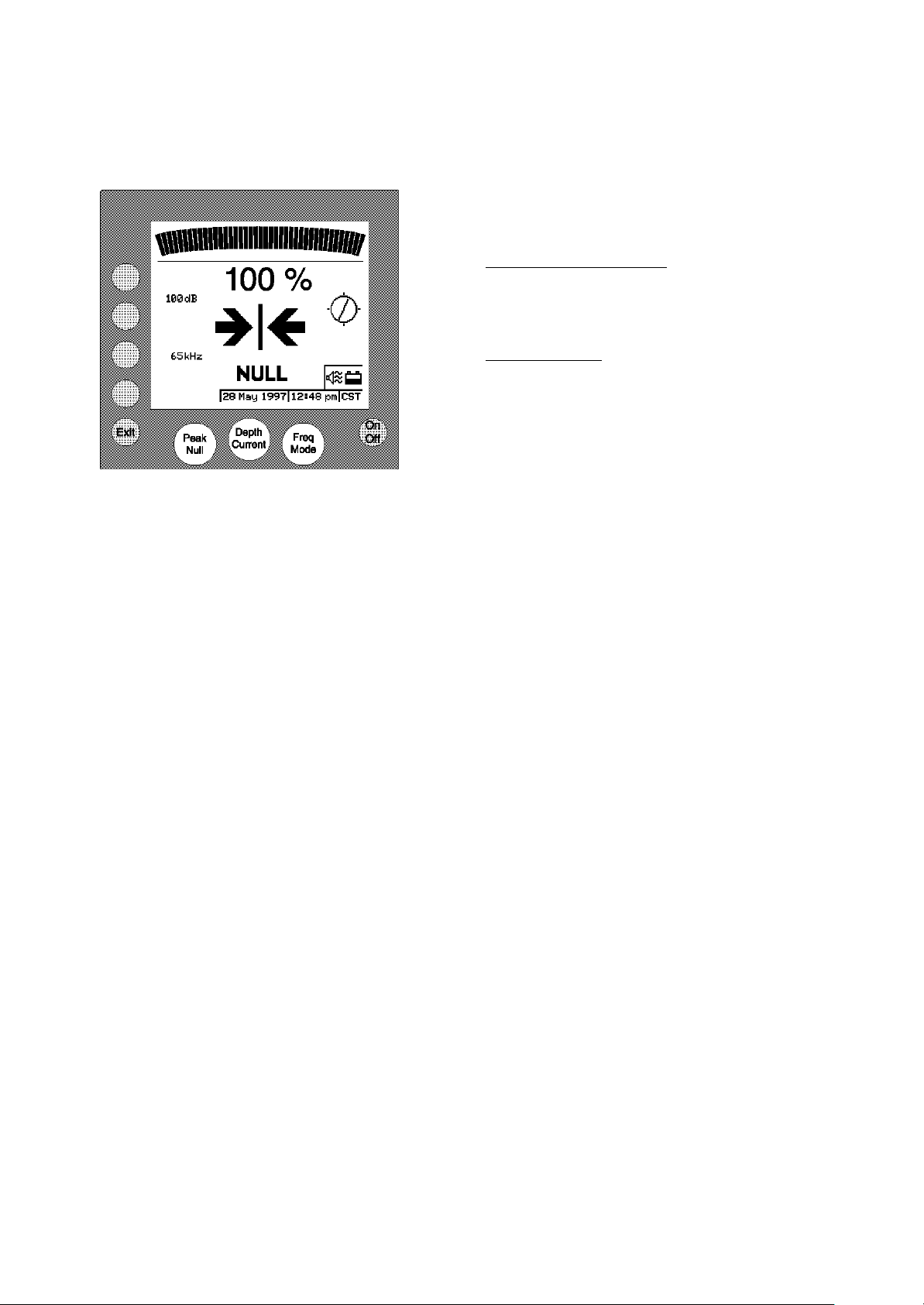
Cable Locate Mode
The Cable Locate screen displays the following:
• Bar Graph - Received signal strength, Peak or
Null.
• Percentage representation of Bar Graph selection
Indication
• Selected gain
• CD arrow - Forward or Reverse
• Cable Orientation Indicator
• Left/Right arrows - Null only
§ Selected frequency
§ Peak/Null indication
§ Battery level indication - five levels
§ Speaker Volume - four levels including Off.
§ Date, Time and Time Zone
§ GPS icon.
Menus
To access the top-level menu screen whilst in Cable
Locate Mode press the exit key.
The top-level menu screen displays the following options:
• System Menu.
• Confirmation Mode.
• Cable Locate.
System Menu
To select the System menu press the key next to the
System Menu arrow.
System menu options are displayed as follows:
• Volume, Contrast, Backlight, Clock (System Setup).
• Upload, Download, Defaults, Test (System Utilities).
• User Preferences.
• PDL-4 Information.
Options are:
• Volume Off, Low, Med, High.
Page 9
Page 16

PDL-4 A.C.ID-M System (with GPS) User Guide
• Backlight Off, On, Auto.
§ Clock -Daylight Saving, Time Zone, Time Format,
Time, Date.
§ Upload, Download, Defaults, Test
Upload Data Log -
Start, Cancel.
Download S/W Upgrade -
Start, Cancel.
• Restore System Defaults -
Confirm Restore, Cancel.
• Self-Test –
Automated tests and results followed by
further manual test options.
• Contrast –
On screen slider adjusted by Lighter/Darker keys or
Gain Control.
User Preferences Screen
The User Preferences screen displays the following
options:
§ GPS power options
• Idle Timer Switch-Off 5, 10, 15, 30, 60 Minutes, or Continuous.
§ Auto gain-
Enabled-Disabled
Page 10
Page 17

PDL-4 A.C.ID-M System (with GPS) User Guide
options:
• VectorBar -
VectorBar screen prompts for the green button
to be pressed.
• SmartProbe -
SmartProbe screen prompts for the green
button to be pressed.
§ A.C.ID Clamp
• Non A.C.ID Confirmation -
Pot Hole, Confirmation Other options.
Cable Locate
Pressing the cable locate menu key takes the PDL-4
into the cable locate screen.
§ Feature Configuration-
This feature is for Radiodetection use
only.
PDL-4 Information Screen
The PDL-4 Information screen displays the following
options:
• Version Status.
Statistics Calibration, Date Shipped.
§ Review A.C.ID Data.
Confirmation Mode
The Confirmation mode screens display the following
Page 11
Page 18

PDL-4 A.C.ID-M System (with GPS) User Guide
Direct Selection
Direct Selection allows quick selection of any menu
item from a list, without having to use the menu
structure.
Press and hold the Exit key for one second to
display the Direct Selection screen.
Select the function required by rotating the Gain
Control to move the highlight bar down (clockwise)
or up (anti-clockwise) then access that function by
pressing the Select key.
VectorBar Operation
Green Button
Press and release to activate the VectorBar - the
adjacent LED will illuminate.
To select a specific A.C.ID-M code press the green
button until the correct code is displayed on the
PDL-4.
To de-activate the VectorBar press and hold the
green button for approximately 5 seconds or until the
red LED extinguishes.
Graduations
Graduations are provided as a guide to the exact
location of the cable or pipe.
VectorBar 20 Operation
Green Button
Press and release to activate the VectorBar 20 - the
adjacent red LED will illuminate.
To select a specific A.C.ID-M code press an release
the green button until the correct code is displayed
on the PDL-4.
To de-activate the VectorBar 20 press and hold the
green button for approximately 5 seconds or until the
red LED extinguishes.
Arm
The VectorBar 20 must only be used with the arm
fully stowed or fully deployed. Do not use the
VectorBar 20 if the arm is not in one of these two
positions.
Page 12
Page 19

PDL-4 A.C.ID-M System (with GPS) User Guide
To deploy the arm, release the catch on the carrying
handle and lift the arm at the green button end of the
VectorBar 20. Continue lifting the arm until it is fully
extended and locks into the fully deployed position.
When the arm is fully deployed, the green LED next
to the swivel mechanism will illuminate. To stow the
arm lift it at the free end until it swings back into the
fully stowed position. Engage the catch in the
carrying handle.
Graduations
Graduations are provided on the side and top of the
VectorBar 20 as a guide to the exact location of the
cable or pipe.
SmartProbe-2 Operation
Green Button
Press and release to activate the SmartProbe-2.
When the extended range SmartProbe-2 is
activated a red LED, located on the head of the unit,
will illuminate to indicate activation.
To select a specific A.C.ID-M code press the green
button until the correct code is displayed on the
PDL-4.
Depth Graduations
Graduations are provided as a guide to the depth of
ground penetration.
Page 13
Page 20

PDL-4 A.C.ID-M System (with GPS) User Guide
Tracing Procedure
Tracing the cable between confirmation locations is
carried out using both Peak and Null modes. Peak
mode is preferred as, in null mode, the signal is
easily distorted.
Peak
Rotate the PDL-4 until the orientation line in the
centre of the Cable Orientation Indicator is aligned
with the North/South marks.
Whilst moving the PDL-4 steadily from side to side,
follow the line of maximum response, keeping the
blade vertical and maintaining Cable Orientation
Indicator alignment.
Null
If required, press the Peak/Null key to select Null
mode and follow the path of the target cable.
Minimum response, with an increased response on
each side, indicates the position of the target cable.
Press the Peak/Null key again to return to Peak
mode.
Locate Procedure
Ensure the LMS-3 transmitter is set to CD mode and
is energising the correct cable.
If a PTx-3 transmitter is generating the signal, ensure
that the LMS-3 is not also energising the cable.
Locate the target cable using Peak mode then check
using Null mode.
Ensure that the PDL-4 is in Peak mode before taking
measurements.
Current Direction (CD)
CD - Reset
Before using Current Direction information a CD
Reset must be carried out.
Set the PDL-4 to CD mode, by pressing the Freq.
Mode key until CD is displayed. With your back to
the transmitter (facing end ground), hold the receiver
blade vertical and across the target cable.
Press the menu key located next to the CD Reset
key.
Page 14
Page 21

PDL-4 A.C.ID-M System (with GPS) User Guide
Select 'Perform CD Reset' and when
prompted confirm that a CD Reset is required.
'CD Reset Successful' is displayed when the CD
Reset is successfully completed. The CD arrow will
point away from the transmitter (towards end ground)
when the PDL-4 is over the target cable.
Depth/Current
Rest the end of the PDL-4 blade on the ground, centre
the level bubble and select Cable Locate Mode, and
then press the Depth/Current key to display the target
cable depth and current.
Confirmation Procedure
Confirmation mode is used for positive identification of
the target cable, and requires an LMS-3 or PTx-3
transmitter to generate the A.C.ID-M signal.
Depending on the transmitter being used apply the
signal as follows:
LMS-3
• Select CD and A.C.ID-M and apply the signal to
the target cable.
• Locate the target cable with the PDL-4 as
previously described.
PTX-3
• Select CD or LF and apply the signal to the target
cable.
• Locate the cable, with the PDL-4, and mark the
approximate position with a suitable marking fluid.
• Select A.C.ID-M on the PTx-3
Cable Identification
VectorBar, VectorBar 20 and Extended Range
VectorBar
Place the VectorBar on the ground above the cable, at
900 to the cable direction, and with no more than 40
tilt from the horizontal on the VectorBar and 300 on the
Extended Range VectorBar. Ensure that the CD arrow
on the VectorBar points away from the transmitter
(towards the end ground point). If the VectorBar is
placed with the arrow pointing towards the transmitter
a “A.C.ID Current Wrong Direction” screen is
displayed.
When the LMS-3 or PTx-3 is set to generate the
A.C.ID-M signal, press the green button on the
VectorBar - the LED will illuminate and remain on.
The VectorBar is now searching for the A.C.ID-M
signal. For customers with more than one A.C.ID-M
code press the button repeatedly until the required
A.C.ID-M code is displayed.
0
Page 15
Page 22

PDL-4 A.C.ID-M System (with GPS) User Guide
Note: Do not move or touch the VectorBar while it is
calculating.
The VectorBar can be deactivated by pressing and
holding the green button, until the LED extinguishes.
When the green button is pressed on the VectorBar
the PDL-4 will automatically switch to VectorBar mode
and display the following information:
VectorBar software version.
VectorBar battery condition.
Tilt angle of bar.
'Waiting for Data'.
'Checking A.C.ID-Mx' progress bar (where x is
the customer unique code)
GPS icon.
After approximately 20 seconds (depending on signal
strength), the VectorBar will normally transmit initial
location data to the PDL-4.
If a GPS position has been fixed the GPS icon will
extinguish.
A 'Checking A.C.ID-Mx' progress bar is displayed and
as each intermediate result is received from the
VectorBar, the PDL-4 increments the Intermediate
Result number by one.
The dotted area represents the region within which the
cable has been detected. The size of this area
indicates the accuracy achieved by this stage of the
measurement cycle.
A number of "Intermediate Result" screens may be
displayed (at intervals of up to 16 seconds) before the
Final Result is displayed. The sequence of
Intermediate Result screens may show increasing
accuracy (i.e., the size of the dotted region may reduce
with each Intermediate Result). It is also possible that
the accuracy may not improve with each Intermediate
Result, or could even deteriorate, e.g. due to a passing
vehicle.
If the VectorBar reports an error, “Error” and a number
are displayed on the wake-up screen.
The numbers and corresponding errors are:
16 Invalid Software Version
32 Invalid Checksum
48 Invalid Calibration
In case of one of these error codes being displayed,
contact your local Radiodetection office.
The PDL-4 will report "A.C.ID-M Current not yet
detected" if the VectorBar does not detect the
Page 16
Page 23

PDL-4 A.C.ID-M System (with GPS) User Guide
A.C.ID-M signal, and the VectorBar will continue
looking.
If the VectorBar is tilted, but by less than 450, the
Intermediate Result screen is displayed.
If the VectorBar has not been placed above the target
cable the 'Reposition the VectorBar' screen will be
displayed indicating the distance and direction that
the VectorBar must be moved.
If the VectorBar has been placed too far away from
the target cable the “Cable out of range” screen will
be displayed indicating direction and approximate
position of the cable.
If the VectorBar is not correctly aligned at 900 to the
target cable a Plan View screen is displayed
indicating the direction in which the VectorBar
If A.C.ID-M confirmation is not achieved the PDL-4
will display 'Not Confirmed'.
When the A.C.ID-M data has been processed the
'CONFIRMED' screen, possibly the first of several will
be displayed. The dotted box represents the region
within which the cable is confirmed - the size of the
box indicates the accuracy achieved.
Indicates A.C.ID-M Confirmation.
A number of Confirmation screens may be displayed
(at intervals of up to 16 seconds) before the Final
Result is displayed. The sequence of Confirmation
screens may show increasing accuracy (i.e. the size
of the box may reduce with each Confirmation
Result). The Final Result is displayed either when the
confirmation box is 6" wide (accuracy +/-3") or the
VectorBar times-out after 5 minutes.
If a GPS position fix has been obtained "GPS OK" will
be displayed in the bottom left-hand side of the
screen.
If "no GPS" is displayed the locator is still obtaining a
GPS position fix. Once the fix has been obtained,
"GPS OK" is displayed.
When GPS data is not immediately available and the
confirm signal from the VectorBar has been received
the display will show "Searching for GPS". After a 10
second delay the display will show "Searching for
GPS. Press 'EXIT' to log without GPS".
Page 17
Page 24

PDL-4 A.C.ID-M System (with GPS) User Guide
If the EXIT button is pressed depth and current will be
logged without GPS data.
If the VectorBar is tilted at an angle of more than 45
the 'Tilt angle too great (450 maximum)' screen is
displayed.
Successful confirmation cannot be achieved until the tilt
angle is reduced to less than 450.
If the VectorBar is tilted, but at an angle of less than
450 the Confirmation screens will be similar to that
shown opposite, which shows a Final Confirmation,
achieved with A.C.ID-M.
SmartProbe-2 or Extended SmartProbe-2
DANGER
Before pushing the SmartProbe-2 into the ground
you must:
Check that the insulating handle grips are not
damaged - Do not use a probe with damaged
insulation.
0
Perform a Power mode sweep of the area to check
for, and locate, power cables.
Always wear electrically insulating rubber gloves
when handling the SmartProbe-2 in the ground.
Use an electrically insulating rubber mat for extra
protection.
Depending on transmitter being used apply the signal
as follows:
LMS-3
• Select CD and A.C.ID-M and apply the signal to the
target cable.
• Locate the target cable with the PDL-4 as
previously described.
PTX-3
• Select CD or LF and apply the signal to the target
cable.
• Locate the cable, with the PDL-4, and mark the
approximate position with a suitable marking fluid.
• Select A.C.ID-M on the PTx-3
Push the SmartProbe-2 into the ground so that the tip
enters the Confirmation Zone (within 5 inches either
side of, and 12 inches above, the target cable) - use
the graduations on the probe as a guide.
Page 18
Page 25

PDL-4 A.C.ID-M System (with GPS) User Guide
The arrow on the top of the SmartProbe-2 must be
pointing along the line of the cable, away from the
LMS-3 transmitter (towards the end ground point).
If the ground is hard, it may be necessary to start
spade, potholer or MED.
Press the SmartProbe-2 green button. For customers
with more than one A.C.ID-M code the button should
be pressed repeatedly until the required A.C.ID-M code
is displayed.
The PDL-4 will automatically switch to SmartProbe2 mode and display the following information:
SmartProbe-2 software version.
SmartProbe-2 battery condition.
'Waiting for Data'.
'Checking A.C.ID-M' progress bar
If the SmartProbe-2 reports an error, 'SmartProbe-2
Error' replaces the 'Checking A.C.ID-M' progress bar
and 'Error Code' followed by a number replaces
'Waiting for Data'.
SmartProbe-2 Error Codes are:
16 Invalid Software Version
32 Invalid Checksum
48 Invalid Calibration
In case of one of these error codes being displayed,
contact your local Radiodetection office.
If the tip of the SmartProbe-2 is within the Confirmation
Zone, and A.C.ID-M current of a sufficient level is
detected, the 'CONFIRMED' () screen is displayed.
If a GPS position fix has been obtained "GPS OK" will
be displayed in the bottom left-hand side of the screen.
If "no GPS" is displayed the locator is still obtaining a
GPS position fix. Once the fix has been obtained,
"GPS OK" is displayed.
When GPS data is not immediately available and the
confirm signal from the SmartProbe 2 has been
received the display will show "Searching for GPS".
After a 10 second delay the display will show
"Searching for GPS. Press 'EXIT' to log without GPS".
If the EXIT button is pressed, depth and current will be
logged without GPS data.
Page 19
Page 26

PDL-4 A.C.ID-M System (with GPS) User Guide
6
If the tip of the SmartProbe-2 is outside the
Confirmation Zone, but not further than 4 ft from the
target cable, the 'Reposition the SmartProbe-2'
screen is displayed at one of two zoom levels
(maximum horizontal displacements of 2 ft or 4 ft).
'Position Estimate' is displayed across the screen.
If the probe tip is close to or within the Confirmation
Zone, and the A.C.ID-M signal is noisy, the
SmartProbe-2 will transmit an intermediate result and
continue measurement . The PDL-4 displays
'Rechecking A.C.ID-M' and a progress bar.
If the SmartProbe 2 has been placed too far away
from the target cable the “Cable out of range” screen
will be displayed indicating direction and approximate
position of the cable.
If the tip of the SmartProbe-2 is within the
confirmation box but at 1800 to the cable the PDL-4
display will show “Current Direction Wrong".
If A.C.ID-M confirmation is not achieved the PDL-4
will display a 'Not Confirmed'.
Penetration Bar
Assembly
Handle and Penetration Rod
Holding the Handle/Safety Lock assembly (1) with
the handle uppermost, ensure that the Safety Lock
(2) is turned fully anti-clockwise. This locks the
upper part of the rod to the handle.
Screw the Penetration Rod (3) to the Handle/Safety
Lock assembly and tighten using two 7/8" AF
spanners.
1
Depth Indicator
Place the Outer Sleeve (4) on a hard surface with the
wider inner diameter uppermost then place the Disc
2
(5) on top of the Outer Sleeve. Press down firmly
and evenly on the Disc, forcing it to fit into the groove
around the Outer Sleeve.
With their wider ends uppermost, place the two
Collets (6) on the Penetration Bar and locate them in
3
the desired depth groove. Fit the 'O' ring (7) over the
Collets ensuring it is correctly seated in the grooves
provided.
7
With the Disc end uppermost, pass the Outer
Sleeve/Disc assembly up the Penetration Bar. Push
the Outer Sleeve/Disc assembly over the Collets/'O'
ring until the Disc end of the Outer Sleeve is flush
with the upper end of the Collets.
Operation
5
Safety Lock
To release the Safety Lock, rest the tip of the
Penetration Bar on the ground and, holding the
handle, rotate the Safety Lock 1/4 turn clockwise.
4
Page 20
Page 27

PDL-4 A.C.ID-M System (with GPS) User Guide
Depth Warning
Raise and lower the handle forcefully to penetrate
the ground until the Disc reaches ground level.
Note: If the Disc jumps off the Outer Sleeve this
indicates that penetration has exceeded the desired
depth.
Further Penetration
Should further penetration be required, remove the
Outer Sleeve and Disc, reposition the Collets/'O' ring
to the desired depth groove, then carry out the Depth
Indicator assembly procedure previously described.
Non A.C.ID Confirmation
Pothole
If it is not possible to use the VectorBar or
SmartProbe-2, or if confirmation could not be
achieved, it may be necessary to dig a pothole for
visual confirmation. Select Pothole then answer ‘Yes’
or ‘No’.
Note: Information will be logged without GPS
Confirmation Other
If it is not possible to confirm the cable's identity
using the VectorBar, Smart Probe-2 or by Potholing,
confirmation must be achieved by other means, e.g.
by referring to plans. Select ‘Confirmation Other’ then
answer ‘Yes’ or ‘No’.
Note: Information will be logged without GPS
Manually logging Data
Although information is automatically logged
whenever the locator is used, it is possible to log
data manually, as follows:
§ Switch on locator
§ Press and hold down second key from the top
(on the left-hand side of the screen
§ Select 'Log Data'
The display returns to the locate screen
If EXIT is pressed, data is logged without logging
GPS data.
Page 21
To log GPS data do not press the EXIT key . GPS
information will be logged.
System Utilities
System Utilities are found in the System Menu and
provide the following options: Upload Data Log,
Download S/W Upgrade, Restore System Defaults
and Self-Test.
Page 28

PDL-4 A.C.ID-M System (with GPS) User Guide
Note:
Before connecting the PDL-4 to a PC or Laptop PC
the following precautions must be taken.
• To reduce the effect of static electricity, wipe the
PDL-4 with a damp cloth.
• Wear an earthed wrist strap.
Upload Data Log
The Upload Data Log option allows the contents of
the PDL-4 Data Log, including GPS information, to
be uploaded to a PC or LMS-3.
Two methods of upload are available:
§ RD Upload-compatible with LMS-3 and PC
upload program
§ Terminal upload-compatible with Windows
HyperTerminal
Connect the PDL-4 to the PC or LMS-3 using an
RS232 cable.
Press the Cancel menu key or the Exit key to return
to the System Utilities menu screen (without
performing an upload).
Press the Start menu key to initiate data transfer.
The 'Uploading Data Log' progress bar is displayed.
If necessary, press the Abort menu key to terminate
the download. 'Upload Aborted!' and 'Press any key'
is displayed for five seconds, unless a key is pressed
or the Gain Control is operated.
After the Data Log is uploaded to the PC or LMS-3
'Upload Successful Press any key' is displayed.
The Data Log is never deleted; the most recent entry
overwrites the oldest.
If the Upload cannot be completed for any reason,
'ERROR' and 'Upload Failed Press any key' is
displayed.
Page 22
Page 29

PDL-4 A.C.ID-M System (with GPS) User Guide
Download Software Upgrade
The Download Software Upgrade option allows new
PDL-4 software to be downloaded from a PC or
LMS-3.
Connect the PDL-4 to the PC using an RS232 cable.
Press the Cancel menu key or the Exit key to return
to the System Utilities menu screen (without
performing a download).
Press the Start menu key to initiate data transfer.
During the download, 'DOWNLOADING NEW
SOFTWARE DO NOT SWITCH OFF!' and the data
transfer percentage completed is displayed.
If the download completes successfully, the PDL-4
will reboot with the new software.
If the download fails for any reason, 'DOWNLOAD
FAILURE!' is displayed.
If the PDL-4 is switched on when there is no valid
software installed 'WAITING FOR SOFTWARE' is
displayed.
Restore System Defaults
The Restore System Defaults option allows the
configuration of the PDL-4 to be set to pre-defined
defaults.
Press the Confirm Restore menu key to confirm and
initiate the request.
Page 23
Page 30

PDL-4 A.C.ID-M System (with GPS) User Guide
Press the Cancel menu key or the Exit key to return
to the System Utilities menu screen (without
restoring defaults).
After the defaults are restored 'System defaults
restored' is displayed for five seconds (unless any
key is pressed or the gain control is operated) and
the receiver enters the operating mode last used.
Self-Test
To initiate a Self-Test, press and hold the On/Off key
for four seconds or select it from the System Utilities
menu.
If the Self-Test was initiated at Power-up the PDL-4
will enter Cable Locate mode on completion of the
Self-Test.
If the Self-Test was initiated from the System
Utilities menu, control returns to that menu on
completion of the Self-Test.
During the Self-Test a list of the automated tests
performed and their results are displayed. The
'Performing Self-Test' progress bar is displayed.
On completion of the automated Self-Test, a Pass or
Fail screen is displayed with the prompt 'Press any
key'.
Pressing any key displays the Optional Tests screen
which allows selection of additional manual tests or
'Exit' to stop further testing.
Page 24
Page 31

PDL-4 A.C.ID-M System (with GPS) User Guide
GPS User Guidelines
Buildings, foliage, and people can block signals from GPS positioning satellites. The ideal location using GPS
is a wide-open space, with an unobstructed view of the sky in all directions. Make sure the unit has an
unobstructed view of the sky before trying to obtain a fix.
Trying to obtain GPS readings in poor coverage areas may result in longer fix times and reduced PDL-4
battery life. To maintain battery life when locating in an inner city area, or any other area where poor
coverage is to be expected, always select the GPS OFF option from the user preferences menu.
Do not leave the unit idling (waiting for a fix to be displayed) in the Display Fix mode for more than two
minutes, as this will drain the battery.
Because GPS positioning satellites orbit the globe the actual number available for position fixing varies
during the day. Long term testing has shown that occasional signal dropouts can occur where no coverage is
available, regardless of location. As satellites appear over the horizon at least every 30 minutes, it is worth
trying to obtain a position fix in difficult GPS locations at different times of the day.
The following guidelines will help in establishing consistent PDL-4 GPS performance.
• Avoid having people crowd around the GPS antenna during a fix.
• Hold the unit away from the body with the face of the GPS antenna flat to the sky.
• Keep the receiver stationary during a fix, as even slight movements will affect the signal levels from the
satellites reaching the antenna.
• Poor or non-existent coverage is to be expected when locating in built-up inner city locations.
• Keep cell telephones, hand held radios and laptop computers away from the GPS antenna during use.
• If the receiver is transported several hundred miles or more it will require a manual cold start command to
re-acquire its new position; this may take several minutes.
• The cold start key can be used to reset the GPS receiver at any time, but frequent use is to be avoided
as fix times are extended and battery life reduced.
• PDL-4 GPS performance is comparable with commercial hand held units, but varying
satellite patterns in the sky will favour different types of GPS antenna so direct comparison may be
misleading.
The GPS performance is not affected by cloud cover, rain, or temperature.
The GPS will not work indoors.
Page 25
Page 32

PDL-4 A.C.ID-M System (with GPS) User Guide
GPS
Show
Confirmation
‘Exit’ pressed or
Log with
Show
Continue looking
Flowchart Showing When GPS Data is Logged on Locate Confirmation
message
From VB,ERVB
SP2
confirmation
screen
Yes (which should be the norm)
fix?
No
GPS Fix is acquired
‘No GPS’ on
confirmation
screen
'GPS OK'
GPS
for GPS
No
new VB locate
started
Yes
Log without
GPS
Page 26
Page 33

PDL-4 A.C.ID-M System (with GPS) User Guide
VectorBar 20 Technical Specification
Description: VB20 VectorBar.
Part No: 10/AA2614.
Physical:
Construction Aluminium Extrusion weatherproof to IP54.
Extending arm to improve depth performance.
Ruggedness Withstands 0.6 metre (2 ft) drops onto concrete (BS EN 60068- 2).
Dimensions
(with arm stowed) 19(H) x 186(W) x 19(D) cm.
7.5(H) x 73(W) x 7.5(D) in.
(with arm deployed) 27(H) X 292(W) X 19(D) cm.
10.5(H) X 115(W) X 7.5(D) in.
Shipping Box Size 25(H) x 200(W) x 30(D) cm.
10(H) x 79(W) x 12(D) in.
Weight 8 kg (17.6 lb).
Shipping Weight 11kg (24 lb).
Operating Modes:
Frequency Sensitivity @ 2.7m Max. Locating Depth (m)
A.C.ID 1
A.C.ID 2
A.C.ID M
Locate Accuracy: Better than 5% of depth on an undistorted signal and with no adjacent signals.
Search Sensors: Six Magnetometers.
100 mA
100 mA
100 mA
2.7m
6m
6m
Batteries: 4 x LR20 (D) 1.5 V alkaline. 8 hours life, nominal @ 20 °C (68 °F) intermittent use.
Page 34

PDL-4 A.C.ID-M System (with GPS) User Guide
Operating
Temperature Range:−−20 °C to +50 °C (−−4 °F to +122 °F).
Environmental Protection:
Shock BS EN 60068-2-29.
Vibration BS EN 60068-2-6.
Freefall BS EN 60068-2-32.
Dust and Water BS EN 60529 (IP 54).
Resistance
Miscellaneous:
Options Tilt Sensor.
Compatibility Radiodetection PDL-4 Locator, Handheld Data Viewer.
Quality Control BS5750/ISO 9001/EN29001.
Compliance Part 15 FCC.
Warranty 12 months.
 Loading...