


QT80

CONTENTS
1.FUNCTIONS & FEATURES .............................................................................1
2.STANDARD ACCESSORIES ...........................................................................
3.INSTALLATION ................................................................................................
4.GETTING ACQUAINTED .................................................................................
5.HOW TO USE YOUR RADIO ........................................................................
6.KEYPAD FUNCTION .....................................................................................1
7.CHANNEL FUNCTION MENU OPERATI N .................................................13
8.PUBLIC DATA FUNCTION MENU OPERATION ..........................................1
9.BACKGROUND FUNCTION MENU OPERATION ........................................1
1 .SPECIFICATIONS ........................................................................................

1. FUNCTIONS & FEATURES
1

2. STANDARD ACCESSORIES
Radio
Screws
Microphone
Hanger
Microphone
Pads
Install bracket
Adjusting screws
Fuse(15A 250V)
2
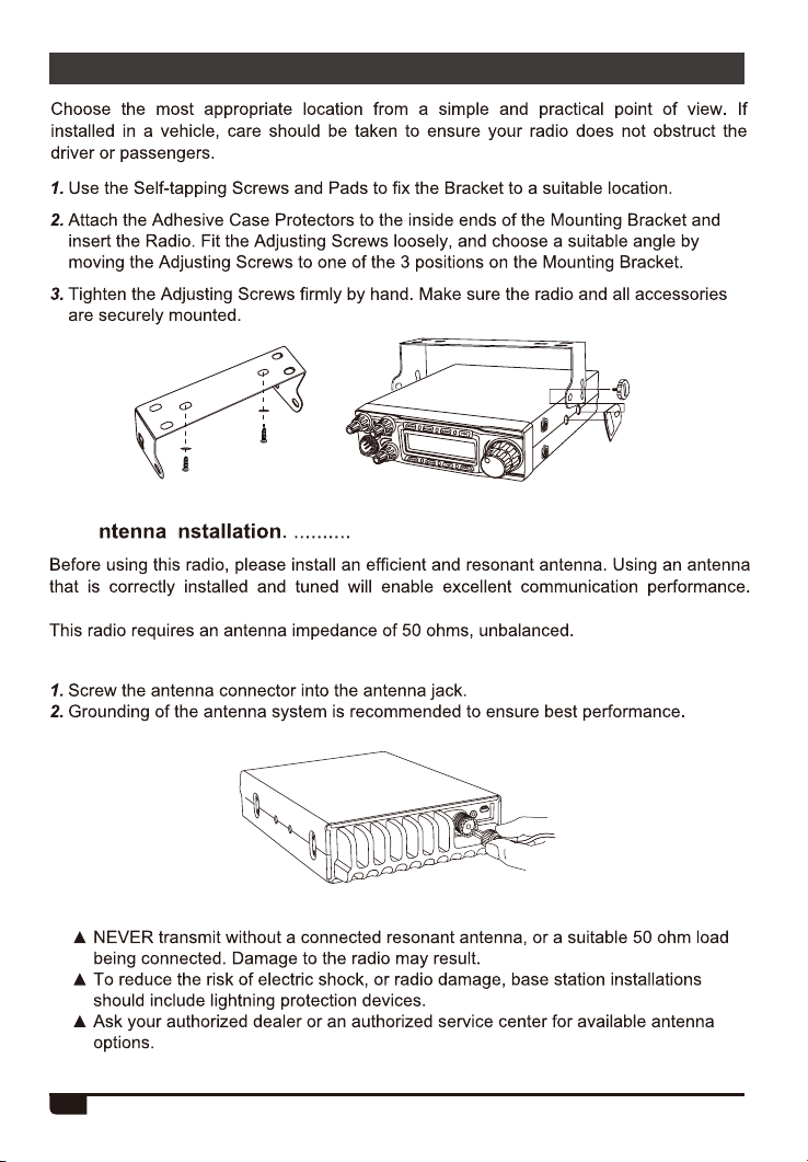
3. INSTALLATION
3.1 A I . ....................................................................
WARNING:
3

3. INSTALLATION
3.
3.2 P ................................... ........................................
3.3 R
Pull the two fuse cover in direction
Replace the b fuse with one, and close the fuse holder.
..........................................................................
and open it.
4

3. INSTALLATION
3. Install Microphone Hanger ....................................................................
3.
Install External Speaker .........................................................................
1. Locate the external speaker in a suitable place.
2. Plug into the speaker jack.
5

4. GETTING ACQUAINTED
4.1 Front Panel ..............................................................................................
10 11 12 1
9
15
16
5 6
No. Key Functions
1 FUNC
2
3
4 SCAN
5 ME
Function Menu key
Switch ode: FM AM USB LSB PA
Switch and: A-I
Scan Scan add Scan delete
Use, tore or elete memory channel
6 TSQ
7 NRC
ctivate / deactivate the NRC function
8 EMG
9
10 RFG
RF Power Control
RF Gain Control
11 SQ
12 CLAR
13 VOL / OFF
14 CH
15
16
Power On/Off; Volume Control
Channel Switch P key
RX/TX Indicator
Microphone Jack
17
2 3 4
71713
8
Channel Keypad lock
14
6

4. GETTING ACQUAINTED
4.2 Rear Panel ...............................................................................................
20 19 18
AN T
EX T SP
DA TA
No. Functions
18 PC Cable Jack
19 External Speaker Jack
20 Antenna Jack
4.3 Microphone .............................................................................................
UP
PTT
Connector
Mic
MIC
EXT.AF
PTT
MI .KEY
Microphone cable
GND
DC
7

4. GETTING ACQUAINTED
4.4 LCD Display ............................................................................................
1 2 3 4 5
25
19
6 7
8
18
9
10
11
12
13
10
11
12
13
14
15
16
17
18
19
20
21
22
23
24
25
24 23 22 21 20
1
Appears during transmi
2
3
4
5
6
7
Appears when using Emergency channel
Appears when using Memory channel
Appears when Echo function is ON
Appears when ffset function is ON
Appears when Hi- ut function is ON
8
9
Appears when Noise Blanker is ON
16
17
working mode
hannel number
14
15
Band name
Appears when +10Khz function is ON
Appears when
Roger eep
No use
Appears when
VOX function
Appears can function
Appears when the Keypad ock function is ON
Appears when NR function
Appears when ASQ
Appears when CTCSS

5. HOW TO USE YOUR RADIO
5.1 OFF/ON Radio .........................................................................................
5.2 Volume Control .......................................................................................
5.3 RF Power Control ...................................................................................
PWR outer shaft to adjust power. Turn it clockwise
to increase power, anti-clockwise to reduce power.
5.4 RF Gain Control ......................................................................................
RFG inner shaft to adjust RF gain. Turn it clockwise
to increase gain, anti-clockwise to reduce gain.
5.5 SQUELCH Control ..................................................................................
SQ
SQ: XX
..............................................................................
CLAR inner shaft to adjust USB/
LSB
5.7 Channel Selection ..................................................................................
increase, anti-clockwise to reduce channel .
5.8 Frequency ontrol ..................................................................................
ress [PUSH]
9

6. KEYPAD FUNCTION
6.1 MEM or ANL/NB ......................................................................................
6.1.1 Using memory channel :
1. Short press
M1-M
, total memory channels .
2. Short press
to enter memory channel, turn CH to choose memory channel.
again to exit memory channel mode.
6.1.2 Store/Delete memory channel :
Store memory channel:
and hold
to choose the location to be stored (M1-M ), then hold
number he
In mode, hold
hen hold
until the turn the CH switch to choose the memory to be deleted
6.2 ANL/NB ....................................................................................................
Press +[NB/ANL] key to enable NB/ANL function "NB/ANL" icon appear on
6.3 MODE or DIM ............................................................................................
6.3.1 MODE
Short press
key to choose mode FM-AM-USB-LSB- PA.
6.3.2 DIM
Press FUNC+MODE key to adjust the backlight brigh ness.
6.4 BAND or COLOR .....................................................................................
6.4.1 BAND
Short press
6.4.2 COLOR
Press +
different color backlights.
6.4.3 VFO
ong press
VF"
10

6. KEYPAD FUNCTION
6.8 NRC or SPLIT .........................................................................................
6.8.1 NRC
Short press
switch ON/OFF the function.
Short press
to switch ON/OFF the function.
ong press
key to start the RX noise reduction function Repeat this operation to
[PTT]
key to st r the TX noise reduction function Repeat this operation
+
key to enter the noise reduction level setting .
6.8.2 SPLIT
Press + "; Repeat this
operation to switch ON/OFF the function.
6.9 EMG .........................................................................................................
Choose EMG channel:
Short press ".
1. Short press
2. Short press
3. Short press
Keypad Lock Function:
1. Long press ";
2. Long press again to unlock the keys.
once to choose CH9;
again to choose CH19;
to return to last normal channel.
12

7. CHANNEL FUNCTION MENU OPERATION
1. Press
FUN", Press to enter menu list
Press [PUSH] to choose the menu
Turn Channel switch to
Press [PUSH] to return to previous menu ress any other key or wait 5
seconds,
the setting will be store
No. Function LCD Display Values and Descriptions
Busy Channel
Lockout
Offset
usy hannel ockout function;
usy hannel ockout function;
offset direction function
Note: Press S key
start CTCSS/DCS scan .
;
;
13
Add/delete
Scan list
to scan list.
added
channel is
not added to scan list.

7. CHANNEL FUNCTION MENU OPERATION
Choose independent channel menu;
Choose public channel menu;
Note: OFF , hidden
channel menu -1 will appear.
14

8. PUBLIC DATA FUNCTION MENU OPERATION
[PUSH]
Hold
No. Function LCD Display Values and Descriptions
for 2 seconds to enter menu list;
H -
NB/ANL
ECHO
10KHz
15
ROGER
encode;
Release PTT to send
Hold PTT+EMG to send
If the M1-M16 storage has
T

9. BACKGROUND FUNCTION MENU OPERATION
Hold [MENU] for 2 seconds to enter menu list;
No. Function LCD Display Values and Descriptions
KEY.BEEP
1
Total 6 levels available.
2
3
S P
M
4
5
MIC.TYPE
6
AM.NPC
VOL.PATH
7
TX
isplays TOT remain time when TX;
Total 45 levels available.
lectret
NPC function.
NPC function.
16

Monitor
8
ECHO
volume level
9
setting
ECHO delay
10
time setting
TOT
11
12
Protection
V
oltage
13
Protection
9. BACKGROUND FUNCTION MENU OPERATION
14 Scan T
15
C
16
17
Dimmer
Backlight
18
19
17
ype

20
21
22
9. BACKGROUND FUNCTION MENU OPERATION
EMG1
EMG2
R
23 ASQ
VOX
24
VOX
25
ensitivity
VOX
26
elay ime
27
RX oise
eduction
28
evel
TX oise
eduction
29
evel
FM eviation
30
evel
18

31
36
9. BACKGROUND FUNCTION MENU OPERATION
SSB
Encode
19
37
Reset

No. LCD Display
1
2
3
4
5
6
7
8
9
1st Function (
Short Press)
2nd Function (
Long Press)
10
11
12
20

13
14
15
16
17
18
21

. SPECIFICATIONS
GENERAL
28.000-29.700MHz (Programmable)
Channel 40 channels (programmable) in each band
Phase-Locked-Loop Synthesizer
10Hz,100Hz,1KHz,5KHz,10KHz,100KHz,1MHz
±5.0 ppm
Temperature Range -20 ~ +50
Microphone
Input Voltage 13.8V
1.27kg
Antenna Connector UHF, SO239
TRANSMITTER
Power Output
15A (with modulation)
Modulation FM/AM/USB/LSB
SSB: 3rd order, more than -25dB; 5th order, more than -35dB
SSB Carrier Suppression 55dB
Unwanted Sideband 50dB
AM/FM: 300 to 3000Hz
SSB: 450 to 2500Hz
Output Impedance 50ohms, unbalanced
RECEIVER
Sensitivity
(All at greater than 1/2 watt of audio output)
Adjacent-Channel Selectivity AM/FM: 60dB SSB: 70dB
Image Rejection More than 65dB
AM/FM: 10.695MHz 1st IF
SSB: 10.695MHz
RF Gain Control 45dB adjustable for optimum signal reception
Automatic Gain Control(AGC)
Audio Output Power 3 watts into 8 ohms
Built-in Speaker 8 ohms, round.
External Speaker(Not Supplied) 8 ohms; disables internal speaker when connected.
Less than 10dB change in audio output for inputs from 10 to
100,000 microvolt.
AM/FM: 300 to 3000Hz SSB: 450 to 2500Hz
, 455KHz 2nd IF
22

SAIN3 LLC
Address: 36 Berkley Drive Newark Delaware 19702 United States
support@radioddity.com
 Loading...