

Radijator EK 06 Smart MONO, EK 12 Smart EU, EK 09 Smart EU, EK 09 Smart MONO EU, EK 16 Smart EU Technical Instructions For Assembly, Operation And Maintenance
...
Živojina Lazića Solunca 6, 36000 Kraljevo, Serbia,
tel: 036/390-140, 390-150, e-mail: radijator@radijator.rs
TECHNICAL INSTRUCTIONS FOR ASSEMBLY,
OPERATION AND MAINTANCE OF ELECTRIC
ENG
BOILER
06-09-12-16-18-21-24-27 kW
EK SMART EU

Table of content
1. Explanation of the symbols and safe work instructions ...................................................................................... 3
1.1 Introduction ................................................................................................................................................... 3
1.2 List of symbols with explanations ................................................................................................................ 3
1.3 General boiler safe work instructions ........................................................................................................... 3
2. Information about the boiler ............................................................................................................................... 5
2.1 Description of the product ............................................................................................................................ 5
2.2 Electro-boiler models .................................................................................................................................... 8
2.3 Declaration of conformity ............................................................................................................................. 8
2.4 Minimum separation distance and flammability of building materials............................................................. 9
2.5 Tools, materials and auxiliary aids ................................................................................................................ 9
2.6 Antifreeze protection .................................................................................................................................... 9
2.7 Waste disposal .............................................................................................................................................. 9
2.8 Scope of delivery .......................................................................................................................................... 9
2.9 Name plate .................................................................................................................................................. 10
2.10 Dimensions and technical data .................................................................................................................. 10
4.1 Caution when assembling the boiler ........................................................................................................... 12
4.2 Clearance around the boiler to floor, wall and ceiling ................................................................................. 13
4.3 Removal of the boiler front casing ............................................................................................................. 13
4.4 Assembly of the boiler ................................................................................................................................. 14
5. Boiler hydraulic scheme ................................................................................................................................... 15
6.1 Position of electrical cable grommets in the boiler ...................................................................................... 18
6.2 Connecting the electric boiler to permanent electrical installation .............................................................. 18
7. Operating the boiler ......................................................................................................................................... 23
7.1 Safety instructions ...................................................................................................................................... 23
7.2 Overview of elements for operating the boiler ........................................................................................... 23
7.3 Alarm .......................................................................................................................................................... 24
7.4 Blockade ..................................................................................................................................................... 24
7.8 Turning the boiler on/off ............................................................................................................................ 25
7.9 Automation deblocade of pump .................................................................................................................. 25
7.9 Communications port.................................................................................................................................. 25
7.11 Master application .................................................................................................................................... 25
7.13 Room thermostat ....................................................................................................................................... 25
8. Hidden menu ................................................................................................................................................ 25
9. Boiler commissioning ...................................................................................................................................... 28
10. Cleaning and maintenance of boiler ............................................................................................................... 28
11. Operating problems and solutions .............................................................................................................. 29
12. Product disposal after use ............................................................................................................................ 29
13. Designing manual .......................................................................................................................................... 30
13.1 Systems to which the boiler may be connected ............................................................................... 30
14. Warranty ......................................................................................................................................................... 31
2

1. Explanation of the symbols and safe work instructions
1.1 Introduction
These technical instructions contain important information about adequate assembly,
commissioning, handling and maintains of the device.
It is intended for authorized installers, authorized service technician’s and end – users of the
electro-boiler.
Please read and retain the instructions for future reference in case of need.
1.2 List of symbols with explanations
Warning symbols
RISK OF ELECTRIC SHOCK
Risk of electric shock symbol is presented by a lightning bolt arrow in a triangle
warning symbol
WARNING
Warning symbol in the text is presented by the warning sign in a triangle
IMPORTANT INFORMATION
Important information for which there is no risk of injury or material damage
SETTINGS
Settings intended for service technicians or experts and end user should not
perform them by themselves.
Key words at the beginning of the safety notice denote the type of hazard and potential
consequences if one does not comply with the measures for preventing hazard.
- NOTE indicates that there might be some material damage.
- CAUTION indicates that there might be minor or moderate bodily injuries.
- WARNING indicates that there might be severe or life-threatening bodily injures.
- DANGER indicates that might be life – threating bodily injuries.
1.3 General boiler safe work instructions
General safety instructions
This device is not intended for use by persons with limited mental or psychophysical
capabilities, as well as by inexperienced persons including children. Children above 8
may handle this device only if an adult is present or if they are instructed for date
handling and are aware of all hazards.
Non-compliance with the safe work instructions may result in severe injuries, death,
material damage, and may jeopardize environment.
Before assembling the boiler professional inspection and control testing of the
electrical installation is required.
All works on the electrical installation should be performed by a competent and
authorized person in accordance with relevant regulations.
Commissioning, maintenance and repair may only be performed by an authorized
service technician.
3

Ensure technical approval of the installation in accordance with the relevant
regulations.
Danger due to compromising one’s own safety in case of need, e.g. in case of fire
Never put yourself in a life-threatening situation. Your safety should always come
first.
Damage due to errors in operating the boiler
Error in operating the device may cause bodily injuries or material damage.
Ensure that only persons who are able to use this boiler adequately have access to it.
Errors in operating the boiler may cause injuries and/or damage to the installations.
Assembly and commissioning of the boiler
Assembly of the boiler should be carried out only by authorized service technician.
The commissioning of the boiler should always be performed only if there is
appropriate pressure in the installation, while the working pressure must be in
accordance with the data of manufacturer. Do not close safety valves in any case, as
the material damage that may be caused by high pressure will thus be avoided.
The boiler should be installed only in a room in which water cannot freeze.
Do not use or store flammable materials (paper, thinner, paint, etc.) near the boiler.
Maintain safe separation distance from the boiler, in accordance with the regulations
in effect.
Life-threatening risk of electric shock
Electrical connection works should be done by authorized service technicians. Please
comply with the connection scheme.
Prior to works on electrical installations disconnect the power supply and ensure that
it may not be accidentally connected again.
The device must not be assembled in damp premises.
Maintained/check-up
We recommend that you sign a contract on inspection/maintenance with an expert
company, so that the inspection and necessary maintenance of the device may be
carried out once a year.
End-user of the boiler is responsible for ensuring that the hearing installation is safe
and environmentally friendly.
Adhere to the safe work instructions in the section
Spree parts
No liability shall be accepted for damage caused by use of spare parts which have not
been delivered by the manufacturer.
Use only original spare parts.
Damage to the system as a result of freezing temperatures
In case of freezing temperatures, protect the heating system from freezing. Heating
water should be drained at the lowest point of the heating system.
Instructions for service technicians
Inform the end-users about the manner of work and the maintenance of the boiler.
Warn the end-users that they must not make any change or repairs on their own.
Ensure that the children do not use this boiler without supervision and not play with it.
4

Hand over boiler technical documentation to the end-user.
Environmental protection/Disposal of waste
Dispose of packaging in an environmentally friendly manner.
Dispose of the boiler in an environmentally friendly manner at the recycling spot.
Cleaning of the boiler
Clean the boiler on the outside with a damp cloth.
2. Information about the boiler
2.1 Description of the product
EK-SMART EU is produced with the following powers:
6kW, 9kW, 12kW, 16kW, 18kW, 21kW, 24kW, 27kW.
Advantages of electric boilers: reliable heating, quiet work, not requiring, a separate room for
installation, small dimensions, low price, high level of operational safety, absence of
chimney, no harmful emissions during operation (environmental protection). Smaller power
boilers of up to 9kW may require Single Phase or Three Phase power supply, while boilers of
greater power exclusively require Three Phase power supply.
In addition to standard elements of an electric boiler, the EK Smart EU electric boiler contains:
expansion vessel, circulation pump, safety valve, filling and drainage tap, automatic air vent,
etc.
The device is equipped with a protective assembly unit which guarantees complete safety.
Heating elements and pump valve are turned on through controller in charge of maximum work
optimisation.
Specially designed logarithm measures the time of work of each heating element and
periodically turns off the heating elements which worked the most and turns on those that
worked the least. In this way, equal exploitation of the heating elements is ensured, which
significantly extends the working life of the product.
Algorithm is designed upon the principle of modulation, so, as the boiler approaches the set
temperature, it reduces its power output and thus achieves maximum comfort with minimum
consumption.
Additional equipment: room thermostat is recommended since they significantly increase the
efficient energy use of the product and retain the same comfort with reduced consumption.
Electric boiler may be used:
1) As a principal source of heating (through radiators: in houses, holiday cottages,
apartments...)
2) As an auxiliary/additional source of heating (systems with a heat pump, solar systems,
pyrolytic boiler...)
3) For heating through heat accumulator (accumulation)
In addition to already mentioned inputs and outputs, EK-Smart EU boiler controller also
contains additional equipment and functions which provide maximum comfort and safety to
the end-user with minimum consumption.
5

Picture 1. Boiler overview: isometric view, front side, left and right side, top side, bottom side
6

Picture
Picture
7 -
Pump
Picture 2. Boiler components
1 - LCD display
2 – Expansion vessel
3 – Automatic air vent
4 – Pressure safety valve
5 – Safety thermostat
6 – Exchanger
3. Connection for hot and cold water
8 - Cold water
9 - Hot water
4. Cross-section of the exchanger
7

2.2 Electro-boiler models
It is important to emphasise that the boilers of 6kW and 9kW are produced in
two versions, with Single Phase and Three Phase connector. The boilers with Single Phase
connectors are EK 06 Smart MONO EU and EK 09 Smart MONO EU, boilers with Three
Phase connectors are EK 06 Smart EU and EK 09 Smart EU. When purchasing the product,
you should emphasise which connector you want. Subsequent “reconnections” are not
approved by the manufacturer.
Electro-boiler models Power
EK 06 Smart EU 6 kW
EK 06 Smart MONO EU 6 kW
EK 09 Smart EU 9 kW
EK 09 Smart MONO EU 9 kW
EK 12 Smart EU
12 kW
EK 16 Smart EU 16 kW
EK 18 Smart EU
EK 21 Smart EU
EK 24 Smart EU
EK 27 Smart EU
Table 1. Electro-boiler models
18 kW
21 kW
24 kW
27 kW
2.3 Declaration of conformity
We declare that these boilers have been examined in accordance with the Directives 2006/95/EC
(Low Voltage Directive - LVD) and 2014/30/EU (Electromagnetic Compatibility Directive EMC).
8

Delivery Item
No of units
Boiler
1
Assembly set
1
Instruction for use
1
Pine wood, larch and spruce wood,
2.4 Minimum separation distance and flammability of building
materials
Minimum separation distance from inflammable materials may differ from country to country.
Please adhere to the regulations on electrical installations and prescribed minimum distances
in your country. The following table shows the classification of flammability of building
materials as per DIN 4102.
Flammability of building materials
A
A1
A2
B Flammable
B1
B2
Non-combustible
Non-combustible
Containing minor
quantities of
flammable additives
(organic ingredients)
Not easily flammable
Flammable
Asbestos, stone, ceramic wall tiles, terracotta,
plaster (without organic additives).
Gypsum-cardboard plates, base felt plates, glass
fibre, plates of AKUMINE, lycopene
RAYOLITE, LIGNOS, VELOX and
HERACLITE
Beech and oak wood, composite wood, felt, plates
of HOBREX, VERSALITE and UMAKART
veneered wood
Easily flammable
B3
Asphalt, cardboard, cellulosic material, tar paper,
particle board, cork, polyurethane, polystyrene,
polyethylene, floor fibres
Table 2. Flammability of building materials per DIN 4102
2.5 Tools, materials and auxiliary aids
For assembly and maintenance of the boiler, standard tools for doing thermo-technical,
plumbing and electrical installations are required.
2.6 Antifreeze protection
If the use of antifreeze additives cannot be avoided, use those additives which are permitted
for heating installations.
2.7 Waste disposal
- Dispose of the packaging in an environmentally friendly manner.
- Dispose of the components which should be replaced in an environmentally friendly
manner.
2.8 Scope of delivery
During delivery of the boiler, adhere to the following:
- Check whether the packaging is undamaged
During delivery.
- Check whether the delivery is complete.
9

2.9 Name plate
Standard plate of the boiler is located on the outside of the boiler and contains the following
technical data: model, voltage, power, serial number, year of production.
2.10 Dimensions and technical data
Picture 5. Dimensions
A=640mm; B=400mm; C=290mm
10

EK 27 Smart
Max
. temperature
of the water
Models
EU
Power
Number of levels of power
Division of levels of power
Mains voltage
Built-in fuse
Min. cross-section of connection
cable
Safety valve
Max. allowable working pressure
Min. allowable working pressure
boiler
Water volume in the boiler lit
Volume of the expansion vessel
Hot water connection
Cold water connection
Boiler dimensions
Handling
kW
Vac
A
mm2
bar
bar
bar
°C
lit
cola
cola
mm
EK 06 Smart MONO EU
EK 06 Smart EU
6 6 9 9 12 16 18 21 24 27
3 3 6 6 6 6 9 9 9 9
3x2 3x2 6x1.5 6x1.5 6x2 6x2.67 9x2 9x2,33 9x2.67 9x3
230 400 230 400 400 400 400 400 400 400
1x32 3x10 1x40 3x16 3x20 3x25 3x32 3x32 3x40 3x40
3x6 5x2.5 3x10 5x2.5 5x4 5x4 5x6 5x6 5x6 5x10
EK 09 Smart MONO EU
EK 09 Smart EU
EK 12 Smart EU
EK 16 Smart EU
EK 18 Smart EU
3
3
0.8
80
11
10
1
1
650x400x290
PCB board
EK 21 Smart EU
Table 3. Technical data
NOTE: Electro-boiler already has built-in fuses, so, when choosing the fuses
outside the electro-boiler, make sure that they are of greater rated current
than those in the electro-boiler. When purchasing the boiler of 6kW or 9kW,
emphasise whether you want a model with Single Phase or Three Phase connection.
EK 24 Smart EU
11

3. Transport of the boiler
NOTE: Transport damages
Pay attention to transport instructions found on the packaging
Use a suitable transport vehicle, e.g. a trolley with a tightening strap.
During the transport, the boiler must be in a lying position.
Avoid blows or collision with various objects.
- Put the packed boiler onto a trolley, if needed tie it with a tightening strap and transport
it to the place where it will be installed.
- Take off the packaging additions.
- Remove the packaging and dispose of it in an environmentally friendly way.
4. Installation of the boiler
CAUNT: Incorrect installation of the boiler may cause injuries or material
damage!
Never install the boiler without the expansion vessel (AG) and safety valve.
Use a suitable transport vehicle, e.g. a trolley with a tightening strap.
NOTE: Material damage may be caused due to freezing!
The boiler should be installed only in a room in which freezing cannot
occur.
4.1 Caution when assembling the boiler
NOTE: Material damage may be caused for failure to adhere to the following
instructions!
Adhere to the instructions for the boiler and all installed components
Prior to installing, pay attention to the following:
- All electrical connections, protection measures and fuses should be connected by a
professional from the authorised service, complying with all the norms and regulations,
as well as local regulations in effect.
- EK Smart boiler has a built-in automatic fuse, the characteristics of which are given in
the Table 3: Technical data.
- Electrical connection must be linked as per the connection schemes.
- After the prescribed installation of the boiler, the ground wire should be connected.
12
- Prior to any works on the heating installations, the power supply should be disconnected.
- Unskilled and unauthorised attempts of connecting under voltage may cause material
damage on the boiler, which may further lead to dangerous electric shocks.
4.2 Clearance around the boiler to floor, wall and ceiling
DANGER: Risk of fire due to flammable materials or liquids!
Do not store flammable materials or liquids in the vicinity of the boiler.
Inform the end-user about the regulations in effect relating to minimum
clearance from easily flammable materials (more information in the
table 2)
- Comply with the regulations on electrical installations and minimum clearance that
are in effect in the relevant country.
- Mount the boiler on the wall in such a way that there remains free space, as shown in
picture 6.
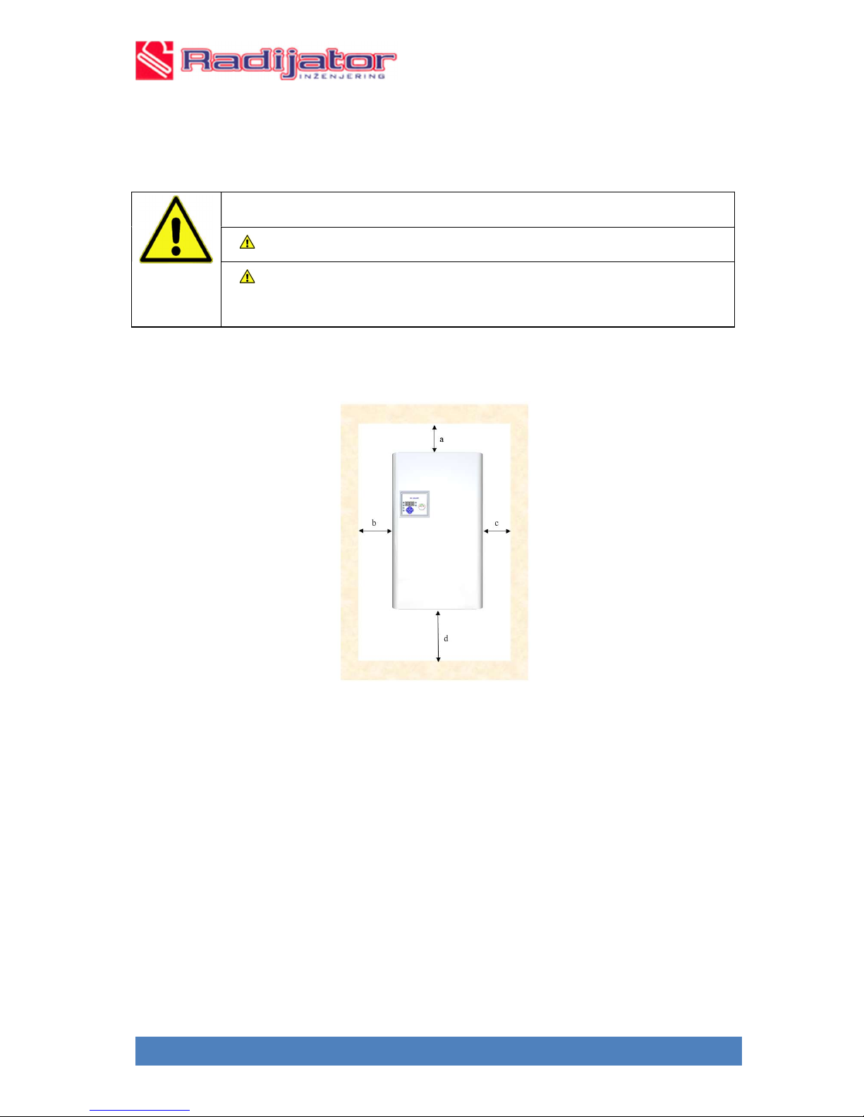
Picture 6. Minimum clearance after the assembly of the boiler
a=60mm; b=c=150mm; d=500mm
13

4.3 Removal of the boiler front casing
Prior to any intervention (removal of the casing), disconnect the boiler
from the installation.
Boiler casing may be removed for easy handling and installation. Boiler removal is
performed in the following way:
1. Unscrew the screws at the left, as shown in the picture.
2. Unscrew the screws at the right, as shown in the picture.
3. Remove the boiler front casing by easily pulling it towards yourself.
Picture 7. Opening of the boiler (removing the boiler front casing)
4.4 Assembly of the boiler
The boiler should be assembled on the wall in a vertical position.
The manufacturer is not responsible for damage caused as a result of
unprofessional assembly.
NOTE: Material damage may be caused by inadequate assembly on the
wall!
This section describes the assembly of the boiler on the wall.
NOTE: The boiler must be assembled vertically on the wall.
Assembly procedure:
1. Mark the position of the hole to be drilled in the wall.
2. Drill holes as per the measures shown in picture 5.
3. Drill holes with adequate drill.
4. Put in the drilled holes the plastic screw anchors, contained in the delivery of
the boiler, or some other screw anchors suitable for non-standard type of wall.
5. Afterwards, put in the screw anchors the screws delivered in the assembly set
(or some other screws). Screws delivered in the assembly set should stick out
from 5 to 10mm.
6. Carefully mount the boiler on the wall.
7. The boiler must be assembled in the vertical position.
Adequate fastener tools should be used.
14

Picture
5. Position of screw anchors for assembly
a=220mm; b=80mm; c=23mm; d=560mm
5. Boiler hydraulic scheme
Heat pipes should be connected in the following manner:
- Connect the cold water connection to the connection 8, picture 3.
- Connect the hot water connection to the connection 9, picture 3.
Filling the boiler with heating water and testing welded joints and tightness:
Testing tightness should be carried out before commissioning the boiler.
DANGER: Injuries and/or material damage may be caused by exceeding pressure
during testing tightness!
High pressure may damage regulation and safety devices, as well as the cylinder
itself.
Fill the boiler up to the pressure that corresponds to the opening pressure of
safety valve.
Comply fully to the pressure of built-in components.
After testing the tightness, open the valves again.
Check whether all pressure regulators and installation safety elements work
properly
15

SRB
DANGER: Health risks due to mixing the drinking water and water from heating
installation!
Comply with the existing regulations and norms related to avoiding mixing
drinking water and water from heating installation.
Comply with the norm EN1717.
DANGER: Risk of fire due to flammable materials or liquids!
Do not store flammable materials or liquids in the vicinity of the boiler.
Inform the end-user about the regulations in effect relating to minimum
clearance from easily flammable materials (more information in the table 2).
NOTE: Damage on installations caused by poor quality of water! Depending on
the water characteristics, there might be damages of corrosion or lime scale on the
heating installations.
Comply with the requests relating to filling water as per VDI2035, i.e. as per
the design documentation and catalogue.
NOTE: Material damage caused by temperature strain. If the boiler is filled in a
warm state, thermal stress may lead to cracks. The boiler will start to leak.
Fill the boiler only in cold state (the temperature of the flow may be
maximum 40°C)
Check the pre-pressure of the expansion vessel.
- Open the filling and drainage tap.
- Slowly fill the boiler.
- At the same time monitor the pressure on the sphygmomanometer. When the working
pressure has been reached, close the filling and drainage tap.
- Purge the boiler through air vent.
- Purge the installation through a valve on the radiator.
- Once the working pressure has been reduced by purging of air, the water in the system
must be refilled.
- Test the tightness in accordance with the regulations in effect.
- Check whether all safety elements work properly.
- If the tightness has been tested and no leakage has been observed, regulate the right
working pressure.
16

SRB
- Take off the hose from the filling and drainage tap.
- Note down the value of the working pressure and water quality in the instruction for
use.
During the first filling or refilling or changing the water
- Comply with the request related to filling water.
Purging and unblocking the heating pump
- Pump installed in this boiler has an automatic manner of purging, therefore,
there is no need to undertake any actions to purge the pump.
When the heating pump is blocked, please do the following:
- If the pump gets blocked after a long period of inactivity, you should unscrew the front
stopper and turn the camshaft using the screwdriver.
- Do this operation carefully to avoid the damage.
Purging the boiler and installation
- Through the screw on the air vent, carefully release the vent and purge the
boiler. This vent is automatic, therefore, if the filling of the installation and
the boiler is carried out properly, additional manual purging will not be
necessary.
- Boiler electrical wiring diagram.
Picture 9. Hydraulic scheme
17

SRB
During connecting the boiler to electrical installation, observe the connection
WARNING
Only qualified person can do the works on electric installations.
Prior to opening the boiler, disconnect the power supply from all poles
and ensure that it is not accidentally connected again.
Comply with the regulations for installation.
IMPORTANT INFORMATIONS
Electric boiler is connected to the permanent electrical installation as per the
connection scheme and with a certain cross-section of voltage cable.
Connection should be made via outer switch for separating poles with
minimum distance between contacts of 3mm.
schemes. Cables must have the prescribed cross-section, and the fuses must
have the prescribed power.
Models EK 06 Smart EU, EK 09 Smart EU, EK 12 Smart EU,
EK 16 Smart EU, EK 18 Smart EU, EK 21 Smart EU, EK 24 Smart EU, EK
27 Smart EU (400V 3N ~).
Modes EK 06 Smart MONO i EK 09 Smart MONO may also be connected
to a Single Phase connection (230V N ~).
6.1 Position of electrical cable grommets in the boiler
This boiler is equipped with two sets of electrical cable grommets. The grommets are
located on the left and right sides.
A set of grommets consists of two rings, with the large ring being intended for voltage
cable and the smaller ring for equipment shown in the hydraulic scheme.
6.2 Connecting the electric boiler to permanent electrical installation
WARNING
The boiler is exclusively connected to permanent electrical installation
- Connection is carried out according to the connection scheme, with a certain crosssection of voltage cable.
- Instead of classic clamp for connecting voltage cable, the boiler contains three-way
automatic switches in which the voltage cable is connected.
according to the existing standards for electrical installations.
Connecting the boiler to permanent electrical installation must be
performed through the device for power supply disconnection from the
network which has a space between contacts of 3mm in all fields that
provide complete disconnection under III category overvoltage
conditions.
18

SRB
- The set of tree-way automatic switches is supplemented by remote voltage relay, this
providing a safety assembly unit which, in addition to short-term over-current
protection, also reacts to thermal overload (a signal from safety thermostat activates
voltage relay) and in the same moment, interrupts the power supply of all three
phases to the boiler.
- In models EK 06 Smart MONO EU and EK 09 Smart MONO EU phase conductor
is connected to single-pole switch (L1).
- In models EK 06-27 Smart EU phase conductors are connected to three-way switch
(L1, L2, and L3).
- Neutral zero conductor is connected to the adequate clamp with the sign N. The
clamp of the zero conductor is blue in colour.
ATTENTION! When connecting phase conductors it is mandatory to
tighten well the screw in automatic switches in order to make as better link
as possible between cable and clamps.
DANGER! If the link between cable and clamp is not tight, there may be
incontrollable heating of the switch and eventually result in breakdown.
NOTE! Remote voltage relay is connected by the manufacturer and
nothing in additionally connected to it.
- When connecting the voltage cable in the boiler, through any of the chosen sets of
grommets, carefully pull the cable to three-way automatic switches, taking care not
to damage sets of cables inside the boiler.
- Additional equipment shown in the hydraulic scheme is connected as per the wishes
of the user.
- After connecting the voltage cable and/or additional equipment, before closing the
boiler, i.e. before the assembly of the front casing, the set of switches and remote
voltage relay should be lifted to ensure power supply in the boiler.
19

SRB
Picture 10. Electrical wiring diagram EK 06 Smart EU
Picture 11. Electrical wiring diagram EK 06 Smart MONO EU
20

SRB
Picture 12. Electrical wiring diagram EK 09 Smart EU, EK 12 Smart EU, EK 15 Smart EU
Picture 13. Electrical wiring diagram EK 09 Smart MONO EU
21

SRB
Q1 Circuit breaker
G1, G2, G3
Relays
20A
X1-1 Terminal Blocks
-
blue
K2 STB thermostat
Picture 14. Electrical wiring diagram EK 18 Smart EU, EK 21 Smart EU, EK 24 Smart EU
LEGEND:
K1 Voltage release H1, H2, H3 Heaters
X1 Terminal Blocks
EK Smart EU
EK 06 Smart EU: H1=3x2kW
X1-2 Terminal Blocks-ground
X1-3 Fuse terminal block 2A
EK 09 Smart EU: H1=H2=3X1,5kW
EK 12 Smart EU: H1=H2=3X2kW
EK 15 Smart EU: H1=H2=3X2,667kW
P1 Pump
P5 Room thermostat connection point
R1 Water temperature sensor KTY 81-210
EK 18 Smart EU: H1=H2=H3=3X2kW
EK 21 Smart EU: H1=H2=H3=3X2.333kW
EK 24 Smart EU: H1=H2=H3=3X2.667kW
EK 27 Smart EU: H1=H2=H3=3X3kW
22

SRB
7. Operating the boiler
7.1 Safety instructions
The user may use and adjust only the functions found in the user menu turn on and turn
off the boiler. All other adjustments should be performed by a professional (authorized
service technician).
Only adults acquainted with the instruction and the manner of work of the boiler may
operate the boiler.
Be careful not to let children without supervision stay in the vicinity of the boiler during
operation.
Do not leave or store flammable materials.
The user must comply with the instruction for use.
Authorized professional who performed the heating installation is obliged to inform the
user about handling, adequate and safe work of the boiler.
7.2 Overview of elements for operating the boiler
1. Position 1 is lighting when pump is active;
2. Position 2 is lighting when room thermostat is active;
3. Position 3 is lighting when system is in heating mode;
4. Position 4 is lighting when system is antfreezing mode;
In the operating mode, under normal conditions, the values of current water temperature in °C
and current boiler power in kW interchange on the display. Depending on which of these
Picture 15. Display look
23

SRB
values is currently on the display, the adequate LED indicator also beams. The temperature
and power interchange approximately every 3 seconds.
7.3 Alarm
Warning bearing the A sign are alarms. Their role is to signalize a potential problem, and that
the parameters are approaching border values for safe work of the system.
A1 – Temperature is too low, that is ≤ 12°C
A2 – Temperature is too high, that is ≥85°C
7.4 Blockade
Warning with the sign E is blockade. Blockade means that one of the vital parameters has
crossed the critical value for safe work of the boiler. Blockade also appears if the controller
detects short circuit/interruption or illogical readout of the temperature. In such a situation, the
controller automatically turns off all relay outputs. Reset of the blockade is performed by
pressing the ON/OFF button. Turn off the controller, remove the cause of the blockade and turn
on the controller again.
E1 –Temperature too low that is ≤ 0°C
E2 –Temperature too high that is ≤ 12°C
E3 – Boiler temperature sensor failure
In case of alarm or blockade, the following is shown on the display:
- For 1.5 seconds, the temperature value is displayed and the temperature indicator beams
- For 2.5 seconds, the error code is displayed and both indicators, for temperature and power
beam
- For 1.5 seconds, the current power value is displayed and the power indicator beams
- For 2.5 seconds, the error code is displayed and both indicators, for temperature and power
beam
In the user menu, it is possible to set the following parameters:
- Temperature (“t” symbol on the display), ranging from 2F28+F29 to 80°C
- Power (“P” symbol on the display), ranging from 1 to the number of heating elements
- Mode (symbol on the display “Fun”, from function) – the value of this parameter set on 1
denotes the heating mode, the value set on 2 denotes antifreeze protection
To set the operating parameters, press the “MODE” key. By pressing multiple times or
holding the “MODE” key, the symbols t, P, FUn will interchange on the display.
By releasing the “MODE” key, the symbols t, P, Fun will interchange on the display.
By releasing the “MODE” key, you will stop at the desired function. Current valid value
recorded for given parameter will soon be shown on the display. By pressing the keys “UP”
(upwards arrow) and “DOWN” (downwards arrow), you may change the value of the
recorded parameter for the chosen function. When you set the desired value of the parameter,
you may leave the menu immediately by pressing OK key or you may change the values of
other parameters. If you do not wish to leave the menu after you have set the value of one
parameter, press MENU key again, the set value of the parameter will be recorded and you
will move to the next parameter from the menu which you may also change and so on.
If you set the value of some parameter and do not press OK, after ten seconds the device will
automatically exit the menu and recorded the set value of the parameter.
Service menu
Press and hold the MENU key, then shortly press the UP key. The sign PAS (from password)
will appear on the display, soon the sign 000 will appear on the display and then the password
should be entered. The password is 64. Electronics does not have the option of changing the
password.
24

SRB
When you enter the password, press OK and the symbols of parameters from the service
menu will appear on the display.
Resetting the boiler
For resetting the boiler, press and hold OK key for a few seconds.
7.8 Turning the boiler on/off
When there is no need for the boiler to work, press ON/OFF button and hold it for at least half
a second. All relay outputs will turn off, as well as the display of the device. When you wish to
turn on the boiler again, press the button again. The device will check the temperature condition
whether it is higher than Tmin, and if it is, the device will start, and if it is not, a message will
appear on the display. Checking whether the T>Tmin when turning on the boiler is not
performed in the antifreeze protection mode.
7.9 Automation deblocade of pump
The pump will run every day at the same time, it will be the time of the day when you switch
boiler off.
If you set the boiler off mode at 6 p.m. the timer will activate the pump every day for 15
minute starting at around 6 p.m.
Important: Do not cut power supply off between heating season.
7.9 Communications port
Communications port RS232 is used for GSM modem or WiFi modem.
7.11 Master application
The input can be used for master applications. If you use this input, you must also set the F25
parameter that determines the behaviour of the boiler.
7.13 Room thermostat
Settings (intended for service technicians):
1. Install the room thermostat at the adequate connection.
2. HIDDEN MENU: Set parameter F04 on 1.
3. Check whether position 2 (symbol ,,t” ) blinking on the main display.
4. When signal from room thermostat is active in the symbol ,,t” (position 2) flash red.
5. When the room thermostat is switched off, pump will be working for three minute more.
8. Hidden menu
Press and hold MENU key, then shortly press the UP key. The sign PAS (from
password) will appear on the display, soon the sign 000 will appear on the display
and then the password should be entered. The password is 64.
25

SRB
Parameters of the hidden menu
Factory
value
Scope of
setting
F01 3/6/9 3/6/9
F02 2,0 1,0-3,0
F04 0 0 or 1
F05 0 0 or 1
F06 45 0 to 99
F07 3 0 to 99
F12 12 0 to 99
Unit DESCRIPTION
-
Number of relay outputs supported by automation
system
kW
Power of one heating element built-in in the boiler
- ROOM THERMOSTAT
0 –room thermostat is installed
1 –room thermostat is not installed
- ANTIFREEZE PROTECTION LIQUID
0 –antifreeze protection liquid is poured in
1 –antifreeze protection liquid is not poured in
°C
°C
Temperature at which the pump turns on
Minimum temperature of water in the boiler at which
the boiler starts up; if the water temperature is lower
than that set by parameter F07, it is impossible to turn
on the boiler.
°C
Minimum value of temperature for alarm
F13 0 0 to 99
F14 85 0 to 99
F15 90 0 to 99
F16 5 0 to 99
F19 3 0 to 6
F27* 15 0-99
F28 0,8 0-99
F29 0,4 0-99
F30 3 1-20
F31 1 0 or 1 -
°C
°C
°C
°C
kW
°C
°C
°C
min
Minimum value of temperature for blockade
Maximum value of temperature for alarm
Maximum value of temperature for blockade
Set temperature of water in boiler for antifreeze
protection mode
Boiler power in the antifreeze protection mode
Difference (hysteresis) boiler and water heater (see
also the parameter F25)
Hysteresis for heating elements**
Hysteresis for heating elements ***
Time of rotation of heating elements
LANGUAGE
1-Serbian language and 0-English language
26

SRB
Hysteresis for heating elements – more about this parameter in the section principle of
operating the electric boiler.
Sz – set boiler power;
Sz-1 – boiler power reduced by one level of power;
Sz-2 – boiler power reduced by two.
Picture 27. Output power of the boiler in the function of temperature and hysteresis
27

SRB
9. Boiler commissioning
NOTE: First commissioning must be carried out by an expert – authorised service technician.
- Before commissioning, check the tightness of the hydraulic network. All the valves in the
network, including thermostat if any, must be in a position (open) which enables smooth water
circulation through the boiler and pipe network. The pressure in the system must be within the
limits prescribed by the Instruction.
- Check whether the device is properly connected to the electrical network. Check whether all
switches on the device and turned off (0), and the regulation thermostat is at the far-left position.
- Turn on the fuses in the distribution cabinet of the house electrical wiring.
- Turn on the automation system of the boiler by pressing ON/OFF button.
- If the room thermostat is connected to the boiler, it should also be turned on.
10. Cleaning and maintenance of boiler
WARNING: Material damage caused by unprofessional maintenance!
Insufficient or unprofessional maintenance of the boiler may result in
damage or destruction of the boiler, as well as in the loss of guarantee.
Ensure regular, comprehensive and professional maintenance of the
heating installation.
Protect electrical components and working units from water damp.
- Use only original spare parts of the manufacturer or those approved by the manufacturer.
For damages resulting from the use of spare parts not delivered by the manufacturer, the
manufacturer does not hold any liability.
Cleaning the boiler
- The boiler should be cleaned on the outside using a wet cloth.
The quantity of newly filled water is reduced in the first days after filling, as a result of
heating. It, thus, creates airbags which obstruct the work of the heating installation.
Testing the working pressure
-Working pressure of the new heating installation should be checked daily at the beginning.
In case of need, fill up the heating installation with water and purge it.
- Later, working pressure should be checked once a month. In case of need, fill up the heating
installation with water and purge it.
- Test the working pressure. If the pressure drops under 1bar, fill up the installation with
water.
- Purge the heating installation.
- Check the working pressure again.
Fill up with water and purge the installation
WARNING: Material damage caused by temperature strain. If the
heating installation is filled in a warm state with cold water, it may result
in cracks.
Heating installation should be filled only in cold state (temperature
of the flow is maximum 40°C).
28

SRB
WARNING: Material damage caused by frequent filling up of water!
Due to frequent filling up of the heating installation with water,
depending on the water characteristics the installation may be
damaged by corrosion or lime scale.
Tightness of the heating installation and functional operation of the
expansion vessel should be tested.
- Connect the hose to the filling and drainage tap.
- Fill the hose with water and set the connection of the hose of the filling and drainage
tap.
- Tighten the hose with a hose clamp and open the filling and drainage tap.
- Slowly fill the heating installation. At the same time, monitor the pressure value on
manometer.
- During the filling, purge the system.
- When the working pressure has been reached, close the filling and drainage tap.
- When the pressure value has been reduced by purging, the water must be filled up.
- Remove the hose from the filling and drainage tap.
11. Operating problems and solutions
1. Boiler is working, but the temperature is unsatisfactory?
- Boiler power is insufficient => Increase the power by selecting another group of heating
elements.
- Selected temperature is insufficient => Increase the temperature on the regulation
thermostat.
- There is excess air in the system => Purge the whole system.
- One of the heating elements is faulty => Call the repair service in order to do the
replacement.
- The boiler does not have all three phases => Call a professional to check.
2. Heating is not functioning and the boiler shows a certain temperature?
- A valve or coil in the system is closed and the flow disabled => Check the valves and open
them if necessary.
- Ball valve on voltage/return line is closed => you must open the valves.
- Pump is not working or is blocked for some reason=> Call a professional for repair.
12. Product disposal after use
Crossed-out “wheelie-bin” symbol on the label of this product means that the product
should not be disposed of with other household waste. In order to prevent potential negative
consequences for the environment and human health, please separate this product from other
waste, so that it could be recycled in a way that is environmentally-friendly.
29

SRB
In accordance with the WEEE Directive 2012/19/EU (Waste Electrical
and Electronic Equipment),Law on Environmental Protection (Official Gazette of the
Republic of Serbia, No.135/2004, 36/2009,36/2009– as amended,72/2009– as
amended,43/2011- decision of the Constitutional Court and 14/2016), Law on Waste
Management (Official Gazette of the Republic of Serbia, No.36/2009,88/2010and14/2016) and
Rulebook on the list of electrical and electronic products, measures restricting or prohibiting
the use of electric and electronic equipment containing hazardous substances, the manner
and procedure for management of waste originating from electrical and electronic products
(Official Gazette of the RS, No. 99/2010).
13. Designing manual
13.1 Systems to which the boiler may be connected
- All the systems for space heating that are designed for temperatures lower than 80°C.
- Closed heating systems.
- Systems in which there is a solid fuel boiler.
ATTENTION! When connecting a boiler to such a system, it is
compulsory to pat attention that both pumps in the system push water in
the same direction in order to prevent collision of flows.
Potential great hydraulic system strains, as well as cracking of some components.
- It may be used as a device for heating sanitary water in the accumulation boiler through the
heat exchanger.
- It may also be used in certain technological processes on condition that there is no need for
water temperature above 60°C.
- It must not be used for direct heating of sanitary water.
30

SRB
14. Warranty
1. Co. “Radiator Engineering” covers different warranty periods for different parts (as
specified further on) only if the following conditions of the warranty are fulfilled:
1.1. The boiler must be connected to the aforementioned hydraulic diagram from the
Technical instructions;
1.2. Wiring connection must be performed in accordance with the Technical Instructions;
1.3. The user must comply with the stated instructions on use and maintenance of the boiler.
2. Warranty statement
We hereby declare:
2.1. That the product has the prescribed and declared quality properties.
2.2. We undertake, at the request of the buyer, if the request for repair is submitted in due
time within the warranty period, to perform, at our expense, all repairs of failures so that the
product works in accordance with the declared properties.
2.3. That the product will work impeccably during the warranty period, if the instructions for
use, operation and assembly are observed.
2.4. That in the warranty period, we will be ready to remove all product failures and keep in
stock all the necessary spare parts.
2.5. The warranty period starts from the DAY OF PURCHASE AND LASTS for 60
MONTHS OR 72 MONTHS FROM THE DATE OF PRODUCTION (the date of production
is on the sticker on the back of the boiler).
2.6. T h e 60 MONTHS WARRANTY IS VALID ONLY IF THE BOILER IS
REGULARLY SERVICED BY THE CENTRAL SERVICE OF CO. “Radiator
Engineering”, within the period specified for the product (in the text below).
2.7. The warranty is valid if the warranty card has been verified by the Seller, if the date of
purchase has been entered and the attached bill presented. IT IS ALSO IMPORTANT TO
HAVE THE ORDER FOR COMMISSIONING (certified by the Authorised Service).
3. Warranty period of 12 months applies to the following parts:
- Heating elements of electro-boiler, under normal conditions of exploitation.
4. Warranty period of 18 months applies to the following parts:
-Automatic switch; name: Acti9iC60
- Voltage relay; name: IMX + off
-Contactors; name: Acti9iCT
5. Warranty period of 24 months applies to the following parts:
-Expansion vessel
-Pump
6. Warranty period does not apply:
6.1. If a regular service is not performed after each heating season;
6.2. For replacement of parts within regular annual maintenance in accordance with the
instructions;
6.3. In case of defects caused by the customer due to improper handling of the product;
6.4. For mechanical defects made during transport and during use (solid objects);
6.5. If the product has been installed improperly, contrary to the applicable regulations in this
area;
31

SRB
6.6. If it has been established that the hydraulic scheme has not been made according to the
recommendations of the company "Radiator Engineering";
6.7. If the customer was using the product over the declared properties and under normal
circumstances.
7. The warranty period shall cease to be valid:
7.1. If it has been established that the failures have been repaired by an unauthorized person
or an unauthorized service.
7.2. If the original parts were not used in the repair;
7.3. W hen the warranty period expires.
8. When reporting failure, it is obligatory to provide the following information:
Name and type of product,
Date of purchase,
Factory number of the boiler,
A brief description of the failure, or shortcomings,
The correct address and contact telephone, email.
9. Regular annual service
Regular service is performed at the end of every heating season in the period from 15th April
to 31st August and is charged according to the set Price list of the company "Radiator
Engineering". The service procedure by technicians who perform regular annual services,
who are authorized by the manufacturer for doing it, include the following operations:
32
 Loading...