


Radicom Research, Inc.
Development Guide
For the
WHM900
Wireless Half Inch Radio Frequency
Module
Revision: July 8, 2005 Preliminary
Information furnished by Radicom Research is believed to be accurate and reliable. However
Radicom Research assumes no responsibility for its use, or any infringement of patents or other
rights of third parties that may result from its use. Radicom Research reserves the right to
1
change circuitry at any time without notice. This document is subject to change without notice.

Table of Contents
Introduction 3
General Specifications 4
Mechanical Specification and Pin Orientation 5
Serial TTL Interface Signal Level Pin Assignments 6
Functional Description of the Serial Interface Signals 7
Antenna Connection 8
FCC Compliance 8
Wireless Data Link Options 10
Point to Point Operation 11
Auto Link Operation 12
Point to Multi-point Operation 13
Suggestions for Improving the Connection 14
Changing from Data Mode to Command Mode 14
The AT Command Set 15
AT Command Listing 16
AT S Registers 25
Command Result Codes 26
Receiver Sensitivity 27
MDK-2001 Development Board 27
MDK-2001 Lights and Description 28
RS232 EIA Serial Port Cable Information 29
Uploading New WHM900 Code 29
Limited Warranty 31
Contacting Radicom Research 33
2

Introduction
The WHM900 RF Module is designed to provide designers a hardware solution for
integrating RF wireless data communication applications into different types of
embedded host systems or remote equipment. The WHM900 requires only a serial 3.3 V
TTL interface and antenna to provide wire-less data communications for these systems.
The designer will be required to implement the necessary hardware to host the WHM900
as well as write the software to control the modules wireless link by using the popular AT
command set. The WHM900 is designed to communicate using Radio Frequencies in the
license free ISM bandwidth (900 – 928 MHz). The wireless link operates at speeds up to
76.8Kbps and will reach distances up to 1000 feet depending on the environment and
operational mode. The modules provide 32 user selectable frequencies with 256 different
channel IDs. Frequency hopping with 50 channels and adjustable transmit levels are also
featured. Data error correction and flow control functions are standard. The modules can
be used for point-to-point, point-to-multi-point, or multiple point-to-point wireless
operation. The WHM900 can also be configured to automatically connect and maintain a
continuous wireless using the modules Auto Link option. This document provides all of
the information integrators need to incorporate the Radicom WHM900 RF Module into
their system for state of the art wireless data communication.
3

General Specifications
.
Radio Frequency: 900 – 928 MHz (License-Free ISM Band)
Range: Up to 1000 feet
Channels: 256 Different User Selectable Channels
Full RF Range Frequency Hopping or 32 User Selectable Frequency Settings
RF Data Rates (bps): 1200, 2400, 4800, 9600, 19.2K, 38.4K, 76.8K
Transmit Levels: AT Command Selectable Range – Max: 0dBm to Min: –20dBm
Modulation Scheme: Frequency Shift Keying (FSK)
Coding: Manchester Mode
Receiver Sensitivity: Data Rate and RF Frequency dependent
Built in Error Correction
Supports Hardware (RTS/CTS) and Software (XON/XOFF) Flow Control
AT Command Data Format: Asynchronous 10 Bit – 1 Start, 8 Data No Parity, 1 Stop
Terminal Data Rate in bits per second (DTE): 300, 1200, 2400, 9600, 19.2K, 57.6K
Terminal Data Rate Tolerance: Over-speed / Under-speed + / - 1%
Interface: Serial TTL compatible I/O (3.3volts)
Voltage Range: 3.0V- 6.0V operation
Uses Popular “AT” command set for easy software configuration
Includes on board NVRAM for storing configuration into memory
Power Consumption: Transmit Mode: 36mA typical
Receive Mode: 28mA typical
Idle Mode (off line) 16mA typical
Low Power Down Mode 4mA typical
Antenna Type: ¼ wave omni-directional with Reverse Polarity SMA Plug (Male)
Antenna Gain: Maximum 2dBi
Input Impedance: 50 ~ Nominal
Physical Dimensions: 1.0(W) x 1.0(L) x 0.3(H) in.
Weight: 0.3oz. or 7g
Operating Temperature: -40C to +85C
FCC: Complies with FCC CFR47 Part 15.247 and 15.249
4
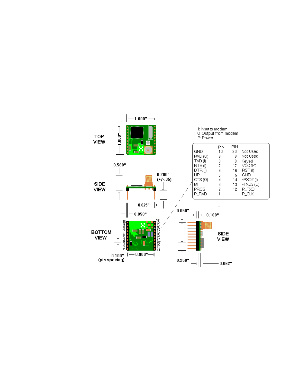
Mechanical Specification and Pin Orientation
5

Serial TTL Interface Signal Level Pin Assignments
The WHM900¹ is designed for easy connection to any standard serial 3.3V TTL
interface. The connection is made through two 10pin headers.
Serial TTL Interface Signal Level Definition:
PIN Number Name Type Comments
1 P_RXD Input Vih: 2.31V ~ 3.6V
Vil: 0V ~ 0.99V
2 PROG Input Vih: 2.31V ~ 3.6V
Vil: 0V ~ 0.99V
3 MI Output Voh: 2.5V ~3.3V
Vol: 0 ~ 0.4V
4 CTS Output Voh: 2.5V ~3.3V
Vol: 0 ~ 0.4V
5 LIP Output Voh: 2.5V ~3.3V
Vol: 0 ~ 0.4V
6 DTR Input Vih: 2.31V ~ 3.6V
Vil: 0V ~ 0.99V
7 RTS Input Vih: 2.31V ~ 3.6V
Vil: 0V ~ 0.99V
8 TXD Input Vih: 2.31V ~ 3.6V
Vil: 0V ~ 0.99V
9 RXD Output Voh: 2.5V ~3.3V
Vol: 0 V~ 0.4V
10 GND ----
11 P_CLK Input Vih: 2.31V ~ 3.6V
Vil: 0V ~ 0.99V
12 P_TXD Output Voh: 2.5V ~3.3V
Vol: 0V~ 0.4V
13 TXD2 Output Voh: 2.5V ~3.3V
Vol: 0V ~ 0.4V
14 RXD2 Input Vih: 2.31V ~ 3.6V
Vil: 0V ~ 0.99V
15 GND ----
16 RST Input
17 VCC Power Vih: 6.0V
Vil: 3.0V
18 N/C Pin has been
removed
19 ---- Not Used
20 ---- Not Used
KEYED
6

Functional Description of the Serial Interface Signals
PIN Name Definition
1 *P_RXD – Program Receive Data – Input pin for uploading flash code into
CC1010 *
2 *PROG – Program – Input pin to activate flash program *
3 MI – Mode Indicator – Low output indicates the module is in Data Mode. If this
output is High, the module is ready to receive commands (Off Line Command
Mode). This signal can also be forced with the AT&C1 command. Note: The MI
signal will always be low when AT\I1 polling is enabled.
4 CTS – Clear to Send – Low output signal from the module telling the DTE, that
it’s OK to send data. The CTS and RTS signals work in conjunction to control the
flow of data in the event of a full data buffer. CTS will always be low unless the
module is in a flow control situation.
5 LIP - Link in Process – Low output indicates that the module is attempting to
establish a link with another module. It also will reflect when data retransmission
is occurring. This signal will constantly toggle during a Frequency Hopping Link.
This LIP signal is disabled when Polling is enabled (See AT\I command)
6 DTR – Data Terminal Ready – A low signal indicates the module is in data mode
and is ready to go online. This signal must be provided to establish a data link.
This signal can also be forced with the AT&D0 command. If connected to a
remote WHM900 and the DTR signal goes high, the module will stop data
communications and go into command mode. If the DTR signal is not used it
should be pulled down to ground.
7 RTS – Request to Send – Low input signal from the DTE to ask if the module is
ready to send data. This signal is used to flow off and on data when the module
buffers are full. RTS works in conjunction with the CTS output signal from the
module. If the RTS signal is not used, it should be pulled down to ground.
8 TXD – Transmit Data – Used for transmitting data from the DTE.
9 RXD – Receive Data – Used for received data path.
10 GND – Ground
11 *P_CLK – Program Clock – Input clock signal for programming flash*
12 *P_TXD- Program Transmit Data – Output for flash programming*
13 *TXD2 – Transmit Debug – Output transmit data for debugging purposes*
14 *RXD2 – Receive Debug – Input receive data for debugging purposes*
15 GND – Ground
16 RST—Module Reset –A 50ms low input will reset the module.
Wait 3 seconds after resetting before issuing commands to the module.
This signal is not required and can be left floating if not used.
17 VCC – Voltage – 3.0 – 6.0 volt input
18 No Pin – Should be Keyed to prevent accidentally plugging module in backwards
19 Not Used – No Connection- Can be used for mounting purposes
20 Not Used – No Connection- Can be used for mounting purposes
* Note: These pins are proprietary and are not required for normal wireless
communication. These pins should be considered not used and have no electrical
signals connected to them.
7

Antenna and Cable Connections
The FCC Part 15 approved WHM900 RF Module comes equipped with a Reverse
Polarity SMA Female Jack for connection to a Reverse Polarity SMA Male plug antenna.
The WHM900 can be purchased with a ¼ Wave Omni-Directional Antenna with 2dBi
gain. The integrator may use other manufacturers antennas providing they are ¼ wave
Omni-Directional type with a gain of 2dBi or lower and meet the FCC Part 15 Antenna
Information listed in the FCC Compliance section of this manual. Note that a Reverse
Polarity SMA Antenna meets the FCC requirement for an antenna connection. A cable
may be added between the WHM900 and the antenna providing it meets the same
connection requirements as the antenna and providing that the finished product still
passes the FCC Part 15 Emissions Requirements.
FCC Compliance
The WHM900 module is designed for integration into a finished product. The WHM900
module is certified to meet the sections 247 and 249 of Part 15 of the FCC Rules. The
finished product containing the module must meet all other testing, labeling, and user’s
information requirements per Part 15 of the FCC rules.
FCC Antenna Information – Per FCC Part 15 rules, no antenna type other than that
furnished or approved by the responsible party (integrator or designer) shall be used with
the device. The use of a permanently attached antenna or an antenna that uses a unique
coupling to the device shall be considered sufficient. The manufacturer may design the
device so that a broken antenna is replaceable by the end user providing that a standard
antenna jack or electrical connector is not used. Refer to the FCC Part 15 Rules and
Regulations for more information.
WARNING: Using an antenna other then the type approved for
use with this product requires the finished product, with the
WHM900 module and new antenna type installed to be tested to
comply with all sections of FCC Part 15 requirements!
8

The enclosed device complies with Part 15 of the FCC Rules. Operation is subject to
the following two conditions: (1) this device may not cause harmful interference and
FCC Part 15 User Information – The manual or installation guide for the finished
product must contain the following information:
This equipment has been tested and found to comply with the limits for a Class B digital
device, pursuant to part 15 of the FCC Rules. These limits are designed to provide
reasonable protection against harmful interference in a residential installation. This
equipment generates, uses and can radiate radio frequency energy and, if not installed and
used in accordance with the instructions, may cause harmful interference to radio
communications. However, there is no guarantee that interference will not occur in a
particular installation. If this equipment does cause harmful interference to radio or
television reception, which can be determined by turning the equipment off and on, the
user is encouraged to try to correct the interference by one or more of the following:
Reorient or relocate the receiving antenna.
Increase the separation between the equipment and receiver.
Consult the dealer or an experienced radio/TV technician for help.
Connect the equipment into an outlet on a circuit different from that to which the
receiver is connected.
Changes or modifications not expressly approved by the party responsible for
compliance could void the user’s authority to operate the equipment!
RF EXPOSURE WARNING - The FCC has developed guidelines to reduce any
possible hazard due to exposure of the human body to electromagnetic radiation The
antenna installation must provide a separation distance of 20cm (8") between the antenna
and all persons.”
FCC Part 15 Labeling Information - When the module is installed in a finished
product with no antenna modifications, the finished product must be labeled with the
following:
The above labeling information may be added to the finished product’s label or can be on
a separate label. The finished product’s label must have it’s own FCC ID (XXX-XXXX)
and the following information.
FCC ID: XXX-XXXXX
(2) this device must accept any interference received, including interference that
may cause undesired operation. Contains FCC ID: K7T-WHM900
Contains FCC ID: K7T-WHM900
9

Wireless Data Link Options
The WHM900 is capable of establishing different types of wireless data links. The three
most common methods are described below. Review these choices to determine which
best fits your application. The mode of operation is determined by issuing specific “AT”
commands to the module. These “AT” commands are also used to select the speed,
frequencies, transmit levels and many other features the WHM900 RF module offers.
Point-to-Point Operation - This method allows the user to set-up single or multiple pointto-point locations by setting different channel IDs, frequencies, and speeds. This method
requires writing software to communicate to each module individually and determine
when to enter the online mode by issuing specific “AT” commands to the module.
Checking the modules I/O signals or result codes can monitor the current status of each
location.
Auto Link Operation - This feature forces the two modules to automatically maintain a
point-to-point connection. If a power outage were to occur or if the link was lost due to
temporary interference, the modules will detect the lost data link and automatically
establish a new wireless data link.
Point to Multi-Point Broadcasting – This mode allows for a Master module to broadcast
data to multiple remote Slave modules. The host software will control all data flow
between the masters and slaves. This method is sometimes referred to as Polling.
10

Point to Point Operation
To demonstrate a simple point-to-point connection, with both modules in their default
state, send the “ ATD” command followed by a <CR> (carriage return or Enter Key) on
one module and then send the “ATA” command followed by a <CR> to the other
module. The “ ATD” command instructs the module to attempt to establish a wireless data
link in the Originate Mode. The “ATA” command instructs the other module to attempt
to establish a wireless data link in the Answer mode. During the LINK process the
originating module will display “LINKING-O” The answering module will display
“ LINKING-A”. If the link is successful, the WHM900 modules will each display the
appropriate “CONNECT” result codes. After the CONNECT result codes are displayed,
the modules will be in On Line Data Mode and data transmission is now possible. The
data link between the modules is always error corrected so data will be received exactly
as it was sent. If data appears to be missing, verify that the data flow control is the same
on the Host and WHM900. The WHM900 defaults to Hardware Flow Control
(RTS/CTS). See the AT\Qn command change the modules flow control settings. If data
throughput is slow, set the Host equipment interface speed the same or higher than the
modules connect speed. The maximum DTE or Host interface speed is 57.6kbps. The
module will automatically detect and adjust to the new DTE speed upon receipt of the
next “ AT” command the module receives.
If ATS7 register time expires and no data link was completed, the module will display the
“ NO CARRIER” result code and will return to the Off Line Command Mode. If the On
Line Data Mode is interrupted, the modules will attempt to re-establish the connection.
Each attempt to re-connect will take approximately 10 seconds. The ATS18 register
determines how many times the module will attempt to re-connect. The “ NO LINK”
result code will be displayed after each failed attempt. If unable to successfully connect
after S18 times, the “ NO CARRIER” result code will be displayed and the modules will
return to the Off Line Command Mode. The module is now ready to accept more
commands.
The answering module can also be set up to automatically enter the ATA listening mode
upon power up or reset. See the S0 register for more information.
11

Auto Link Operation
Setting and storing the modules Auto Link settings into the modules Non Volatile
Memory (NVRAM) allows the pre-configuring of the modules DTE speed, data link
speed, transmit levels, frequency of operation, and channel Ids for establishing a constant
wireless data link. Once these parameters are stored, the module will be conditioned to
automatically maintain a connection. In the event of a power outage, the modules will
automatically attempt to reconnect to each other when power is restored. If the wireless
data link is lost due to any other reasons, the modules will detect the lost link and attempt
to automatically re-establish the link forever.
To configure the modules for Auto Link operation using the modules in their default
state, one module must be set up for Answer Mode and the other must be set for Originate
Mode. Send the “ ATS0=1&W” command followed by a <CR> (carriage return or Enter
Key) to one module and Send the “ATS0=2&W” command followed by a <CR>
(carriage return or Enter Key) to other module. Once these command strings are issued,
the modules are set up for Auto Link Operation. After a five second delay they will
attempt to automatically establish a wireless data link. During the link process the
originating module will display “LINKING-O” The answering module will display
“ LINKING-A”. If the link is successful, the WHM900 modules will each display the
appropriate “CONNECT” result codes. After the CONNECT result codes are displayed,
the modules will be in On Line Data Mode and data transmission is now possible. The
data link between the modules is always error corrected so data will be received exactly
as it was sent. If data appears to be missing, verify that the data flow control is the same
on the Host and WHM900. The WHM900 defaults to Hardware Flow Control
(RTS/CTS). See the AT\Qn command change the modules flow control settings. If data
throughput is slow, set the Host equipment interface speed the same or higher than the
modules connect speed. The maximum DTE or Host interface speed is 57.6kbps. The
module will automatically detect and adjust to the new DTE speed upon receipt of the
next “ AT” command the module receives.
If the ATS7 Register time expires and no data link was completed, the modules will
display the NO CARRIER result code and begin the link negotiation process again. This
process will continue indefinitely until a wireless data link is established. If a wireless
data link is interrupted, the modules will attempt to re-establish the connection. Each
attempt to re-connect will take approximately 10 seconds. The ATS18 Register
determines how many times the module will attempt to re-connect. The “ NO LINK”
result code will be displayed after each failed attempt. If unable to successfully connect,
the “ NO CARRIER” result code will be displayed. This routine will constantly repeat
until the modules re-establish a wireless data link.
Note: Always save the Auto Link options as well as any other command parameters with
the AT&W command. When the module is reset or powered up it will always revert to
these saved settings. The module will also power up to the DTE speed that the last
AT&W was issued.
12

Point to Multi-point Operation
In this mode, a Master module will broadcast or transmit data to all available Slave
modules operating on the same frequency. All Slaves will receive data from the Master
and the host software will determine which of the Slaves transmit data back to the
Master. It is invalid for more than one Slave to respond at the same time. The Master will
only receive data that is transmitted by the Slave. Slave-to-Slave operation is not
possible. It is however possible to have several Masters which allows communication
from 2 or more Masters to broadcast to all available Slaves. Only one Master should
transmit data at a time. All data is transmitted in packets with CRC checksums. If the
received data is corrupted, the module will disregard it and not forward it to the host. The
host is responsible for the data link integrity.
To set up for Point To Multi-point operation enter AT\I1 command followed by the
carriage return character (<CR> or the Enter key), to both the Master and Slave modules.
Issue ATS0=2<CR> to the Master or broadcasting module(s). The module will respond
by sending “OK” result code. The Master module will wait 5 seconds then display the
appropriate CONNECT result code followed by “ MASTER @ 9.15.02M”. Set-up all
Slave Modules by entering the ATS0=1<CR>. The Slave modules will respond with the
“ OK” result code. The Slave modules will wait 5 seconds then display the appropriate
CONNECT result code followed by “SLAVE @ 9.15.02M”. The modules are now ready
for operation.
Setting and storing the modules settings into the modules Non Volatile Memory
(NVRAM) with the AT&W command will allow the modules to retain their DTE speed
and command settings in the event of a power loss.
Notes: Care should be taken when implementing this method. Some commands or
features may work differently in this mode.
1) The CONNECT and the MI signal indicates that the module is in broadcast mode, not
that the module is in data mode.
2) The –An, Bn, Mn, %Sn, \Tn, %Un, commands and S7, S18 registers are invalid if \I1
is set.
3) Frequency Hopping is not available in this mode.
13

Suggestions for Improving the Connection
Optimum performance between two WHM900 modules will vary depending on the
proximity of the two modules and the type of antenna used. Try adjusting the antenna for
best reception. Start by positioning the antenna straight up and adjust as necessary.
Pointing the antenna towards the other module will not improve the reception. Do not
place the antenna next to large pieces of metal because it will cause additional
interference. The distance between the two modules will effect the modules connect
speed and data throughput. Operating two modules too close to each will cause
saturation of the receiver. Allow at least three feet separation between the two modules.
The WHM900 data rate (AT%Mn) and transmit level (AT%An) commands can be used
to help optimize the modules performance. Setting the data rate lower (AT%Mn) and
increasing the transmit level (AT%An) will increase the distance but lower the data
throughput. If interference from other digital devices is suspected, try changing the
frequency that the modules are operating on. See the AT%Fn command. The module
frequency hopping option may be useful to counter interference. See the ATBn
command.
Changing from Data Mode To Command Mode
The WHM900 has the capability of exiting the On Line Data Mode to either change or
check specific module settings then return to the On Line Data Mode or to end the RF
data link and return to the Off Line Command Mode.
1) The On Line Command Mode can be entered if the host transmits three consecutive
“ +” s. The “+++” must be protected by a one second delay before and after it is sent.
When the module detects this sequence, the OK result code will be displayed and the
module will be in the On Line Command Mode. You are now able to enter specific
commands to change or check module parameters. An example would be to change
the modules transmit level with the AT%An command. After changing or checking
the settings, you must enter the ATO command to return to the On Line Data Mode.
To end the data link and return to the Off Line Command Mode, enter the ATZ or
ATH command. The ATZ command will end the data link and also reset the module
to its stored configuration. The ATH command will end the data link without
resetting the module. If frequency hopping is enabled only the “ATH” and “ ATZ”
command are valid. Once the module is in the Off Line Command Mode the “ATD”
and “ ATA” commands must be entered to return to the On Line Data Mode.
2) Setting the Inactivity Timeout with the AT\Tn command can be used to exit the On
Line Data Mode. If no data is transmitted or received in the time specified by the
AT\Tn setting, the module will disconnect and return to the Off Line Command Mode.
3) Resetting the modules power or toggling the Reset Line (Pin #16) will end the RF
Data Link and return the module to the Off Line Command Mode.
14

4) Toggling the DTR signal (Pin #6) from On to Off can be used to put the module in
either the On Line Command Mode or Off Line Command Mode. If AT&D1 is set
and the DTR signal is turned off, the module will enter the On Line Command Mode
and will require an ATO to return on line or an ATH to disconnect. If AT&D2 is set
and DTR is turned off, the module will enter the Off Line Command Mode. To enter
the On Line Data Mode, DTR must be turned on and a new connection must be
established with the “ ATA” or “ATD” commands.
The AT Command Set
Controlling the WHM900 functions is accomplished by issuing “AT” commands from
the Host equipment. The module will automatically accept and process “ AT” commands
at 1200, 2400, 9600, 19.2K, or 57.6K (Bits per second). This speed is commonly referred
to as the DTE (Data Terminal Equipment) speed. The Parity setting MUST be 8 data bits,
No Parity, and 1 stop bit (8N1). For each command issued, the module will respond with
a result code informing you of the modules status. The format of a basic “AT” command
and result code is as follows:
AT <Command> <CR>
OK
Meaning:
AT = ATtention what follows is a command
<Command> = any valid command or parameter
<CR> = Carriage Return or Enter Key to process the preceding “AT” command
OK = AT Command Result code meaning that the module has accepted the command
The command line length is the “AT” plus 40 additional commands or parameters plus
the Carriage Return character. This means that no command line may exceed a total of 43
total characters. Exceeding the command line length limit or entering an invalid AT
command string will cause the module to respond with the “ERROR” result code.
15

AT Command Listing
This section will list the basic commands required for most applications. Some
commands have parameters associated with them. The format is as follows:
AT&Dn<CR> where “n” equals the parameter, usually 0 or 1. If a command with a
parameter (n) is issued without the (n), the module will assume that n = 0. For example
issuing AT&D<CR> would equivalent to AT&D0<CR>. The following lists the
available AT commands.
AT Commands
A/ Repeat previous command. The A/ command is not preceded by an “ AT”.
A Listen for Incoming RF Signal - This command instructs the module to listen for
an incoming RF signal from a remote WHM900 and attempt to establish a
wireless data link. The other module must issue an “ ATD” command. When
these commands are entered both modules will display the appropriate
“ LINKING result code. If the data link is successful both modules will then
display the “ CONNECT” result code to reflect the speed at which the two
modules have connected. If no link is established before the time set in S7 register
has elapsed, the module will issue the “ NO CARRIER” result code and return to
the “ AT” off line command mode. When ATA and ATS7=255, the module will
always listen for an incoming RF signal at the frequency defined by the AT%F
command. See the AT–An or AT&Dn commands to the exit the always listening
mode.
-An Any Key Abort Command- This command determines whether any key will abort
an in process link negotiation or be ignored.
-A1 Any Key entered will abort the link negotiation (default).
-A0 Any Key entered during the link negotiation will be ignored.
\An Select Maximum Block Size – The module will operate in an error corrected link
using a maximum block size determined by the parameter supplied.
\A0 8 maximum character blocks.
\A1 16 maximum character blocks.
\A2 24 maximum character blocks.
\A3 32 maximum character blocks (default).
16

%An Transmit Level. This command will set the modules transmit level. Use the chart
below to set the modules transmit level. The default is 0dBm. Issuing
AT%A160<CR> will set the module transmit level to 0dBm. The FCC has placed
transmit level limits on particular frequencies. In those cases the %Fn (Set
Frequency Command) will override and limit the %An Transmit setting. The %A
Command is invalid in Frequency Hopping Mode
Transmit
Level
-20dBm AT%A2 -6dBm AT%A14
-18dBm AT%A3 -5dBm AT%A15
-16dBm AT%A4 -4dBm AT%A80
-14dBm AT%A5 -3dBm AT%A96
-13dBm AT%A6 -2dBm* AT%A112
-12dBm AT%A7 -1dBm AT%A128
-11dBm AT%A8 0dBm AT%A160
-10dBm AT%A9 +1dBm AT%A192
-9dBm AT%A10 +2dBm AT%A224
-8dBm AT%A11 +3dBm AT%A240
-7dBm AT%A12 +4dBm AT%A255
*Default setting of the AT%A command
AT%A Setting Transmit
Level
AT%A Setting
Bn Frequency Hopping – When enabled the modules will constantly change the
frequencies that they are communicating on. When Frequency Hopping is enabled
the module uses its full range of 50 different frequencies. The starting frequencies
are defined by the AT%Fn command. Both modules must be set to ATB1 and use
the same AT %Fn setting.
B0 Frequency Hopping disabled (default)
B1 Frequency Hopping enabled
Frequency Hopping Notes: When enabled, ATI9 and ATMn commands
are invalid. The On Line Command Mode can only be used to disconnect
with the ATH or ATZ command. Frequency Hopping should only be used if
constant interference is inhibiting successful data transfers. Data throughput
may be slower when hopping is enabled. Frequency Hopping is invalid
when module is operating in Broadcast mode (AT\I1). The %A transmit
level command is invalid and the transmit level will always be 4dBm.
17

&Cn Mode Indicator - The Mode Indicate Pin (3) reflects whether the module is In
Data Mode or Command Mode. A Low output indicates the module is in
connected (Data Mode). If this output is High, the module is ready to receive
commands (Command Mode). The MI signal can be forced with the AT&Cn
command.
&C0 Mode Indicate signal is forced high.
&C1 Mode Indicate signal will indicate whether the module is in On Line Data
Mode or Off Line Command Mode (default).
D Initiate Wireless RF Link - This command instructs the module to initiate a
wireless RF link with a remote WHM900. The remote module must enter an
“ ATA” command. The module will wait the amount of time defined in module
resister ATS7 to establish a RF link with the remote module. If the link is
unsuccessful, the module will return to the off line command mode. The ATD
command is also used for auto pole detection for all available frequencies and
IDs. See the ATMn or AT%U commands for more information on using the auto
pole search option.
&Dn DTR (Data Terminal Ready) Option. The DTR signal must be provided either by
command or an incoming signal from the host equipment to enable data
communications between two WHM900 modules. If either the ATA or the ATD
commands are issued without a DTR signal available, the “ NO DTR “ result code
will be displayed.
&D0 Ignores DTR (DTR signal is forced on Pin 6) (default).
&D1 An On-to-Off transition will cause the mode to enter the On Line
Command Mode. It has the same effect as entering the Escape code (+++).
This allows you to change certain commands without losing the data link
and then go back into the Data Mode with the ATO<CR> command.
&D2 Host equipment controls the DTR signal. The module assumes command
state and disables data communication when detecting ON-to-OFF
transition of DTR. To establish a data communications, DTR must be On
and an ATA or ATD must be issued
&D3 Module responds to a DTR On-to-Off transition as though a reset
command (ATZ) had been received.
18

En Command Echo. The ATEn command determines whether the AT command
string will be echoed back to the Host DTE when issued.
E0 Disables command echo.
E1 Enables command echo (default).
&F Restore factory configuration (profile). The AT&F command will reset all
commands and registers to their factory default values. Any changes to the
module settings will be lost when the AT&F command is issued unless they were
previously saved into the module memory with the AT&W command.
%Fn Select Frequency - This command selects which frequency the modules will use
to establish a wireless data link. For two modules to connect, they must operate
on the same frequency. If Frequency Hopping is selected the modules will
constantly be changing frequencies that they operate on. Frequency Hopping
starting frequency is determined by the AT%F setting. See for ATBn command to
enable or disable the Frequency Hopping. The %F command may override some
%A transmit levels due to FFC requirements.
%Fn Frequency %Fn Frequency
%F0 915.02MHz %F16 914.50MHz
%F1 903.00MHz %F17 910.00MHz
%F2 905.00MHz %F18 919.50MHz
%F3 907.00MHz %F19 910.50MHz
%F4 909.00MHz %F20 913.50MHz
%F5 911.00MHz %F21 911.05MHz
%F6 913.00MHz %F22 912.00MHz
%F7 915.05MHz %F23 917.50MHz
%F8 917.00MHz %F24 907.50MHz
%F9 919.00MHz %F25 903.50MHz
%F10 921.00MHz %F26 926.50MHz
%F11 923.00MHz %F27 922.00MHz
%F12 925.00MHz %F28 909.50MHz
%F13 927.00MHz %F29 905.50MHz
%F14 912.50MHz %F30 918.50MHz
%F15 914.00MHz %F31 925.50MHz
= Default Frequency %F0 (915.02MHz)
19

H Exit RF Link – This command can be used to end an RF wireless On Line session.
The ATH command can only be used if the module is placed in the On Line
Command Mode by entering the “ +++” escape mode sequence. See “ Changing
from Data mode to Command Mode” for more information on using this
command.
I4 Firmware Identification - This command will display the modules current
firmware version. Example: 09/27/2004-001 Wireless V 1.00
I8 Enter Power Down Mode – When the module is in off line idle mode and ATI8 is
issued, the module will enter the Low Power Down Mode. The module will exit
this mode when the module receives a 50 ms reset. Wait 3 seconds after the reset
prior to entering any AT commands
I9 Receive signal strength indicator - When on line and you enter the command
mode using the +++ escape sequence, you are able to issue the ATI9 command to
display the modules Receive Signal strength. If this command is issued when the
modules are not connected, this command will display the last Signal Strength
Received. This command is invalid if Frequency Hopping is enabled. Use the
following formula to calculate the approximate value in decibels where the ATI9
result displayed is equal to “n”
(-48.8 X n/155 -57.2) = dBm receive level
\In Select Point to Multi-Point Polling operation. This command is used in
conjunction with the ATS0 command to set the modules up for Broadcast from a
Master Module to one or more Slave modules. See Point to Multi-point operation
for more information.
\I0 Disable Point to Multi-point option
\I1 Enable Point to Multi-point option
20

Mn Auto Pole – This command enables the module to automatically search for any
available IDs or Frequencies. Select ATM2 for an ID search or ATM3 for a
frequency search. For Point-to-Point search operation issue the ATD command.
For Auto Link search operation issue the ATS0=2 command. If the module finds
a valid ID (M2) or frequency (M3), the two modules will automatically connect
and display the appropriate connect result codes. After the modules disconnect the
module will then search for the next available ID or frequency as defined by the
M command. If the search began with the ATD command, you must enter another
ATD to continue the search. If the search began with the ATS0=2 command, the
module will start the search automatically. The module will search until ATS7
time has elapsed. Increasing the ATS7 time will allow for a longer search to take
place. If ATS0=2 was used the modules will continuously loop back into the
search mode until the search is stopped by either entering the either the ATS0=0
or ATM1 command.
NOTES: The Mn command will not work if Frequency hopping option enabled.
The Auto Pole option won’ t work if the modules are set to different RF Data
Rates (AT%Mn). To search for a specific range of IDs, see the AT%U command.
The Auto Pole option is invalid in Point to Multi-Point operation.
M1 Disable Auto Pole (default)
M2 Search for any available ID and connect. The module will search the AT%F
frequency for any valid ID. If the module detects a valid ID on the
frequency it is searching, the module will connect and enter the On Line
Data Mode.
M3 Search for any available frequency and connect. The module will begin
searching beginning with the frequency defined by the AT%F setting and
then search all frequencies until it either connects or times out. The modules
will only connect if a valid ID (AT%Sn) has been detected.
%Mn Select RF Data Rate – This command determines the speed of the wireless link.
Both modules must be set to the same speed.
%M0 = 76.8Kbps %M4 = 4800bps
%M1 = 38.4Kbps %M5 = 2400bps
%M2 = 19.2Kbps (default) %M6 = 1200bps
%M3 = 9600bps
21

O Return to Data Mode - The ATO command is used to exit the On Line Command
Mode and return to the On Line Data Mode. When this command is entered the
module will respond with the appropriate CONNECT result code. This command
is invalid if frequency hopping is enabled. See Changing from Data Mode To
Command Mode for more information on the ATO command.
Qn Quiet results codes control – Each time an “AT” command is issued, the module
will respond with a response or result code. The ATQn command determines if
the module will issue result codes to the DTE or host equipment.
Q0 Issue result codes to the DTE (default).
Q1 Do not issue result codes to the DTE.
\Qn Flow control- Controls the data flow between the modules and host.
\Q0 Disables flow control.
\Q1 Bi-directional XON/XOFF flow control
\Q2 CTS hardware flow control (default)
\Q3 Enables RTS/CTS Hardware flow control
\Q4 Enables XON/XOFF Send only flow control.
\Tn Inactivity Timeout – Determines the period of inactivity before the module will
drop the link and return to the command mode. The value of “n” is in one minute
increments. The default is “0”.
\S Display current configuration. The AT\S command will display the modules
Active Profile as well as the modules Stored Profiles.
Sr Read or write to S-register “r”. The ATSr command allows the reading and
writing of new values any valid S register.
ATSr= n Sets S-register “ r” to the value “n”
ATSr? Reports the value of S-register “r”
22

%Sn Select Channel ID – Use this command to choose one of the available 256
Channel IDs that you want to use to communicate. To communicate with one of
more remote modules, they must all use the same unique Channel Id Number.
The channel range is between 0 and 255. The default is Channel 255. The
command format is as follows:
AT%S132<CR> Select Channel 132
OK Channel Selection OK
%Un Search for a specific range of IDs and Connect – This feature uses the AT%Sn
and AT%Un commands to define a specific range of IDs for the module to search
for and connect to. In order for the search and connect feature to work, the
modules frequency (AT%Fn) and speed (AT%Mn) must be the same.
Example: To search for any valid IDs between 24 and 32, enter AT%S24 and then
AT%U32. For Point-to-Point search operation issue the ATD command. For Auto
Link search operation issue the ATS0=2 command. The search would begin with
ID 24 and end with ID 32. If any valid ID is found, the module would connect,
display the appropriate result codes and enter the On Line Data Mode. After the
module disconnects, the module will then search for the next ID in the specified
range. The module will only search for Valid IDs in the range defined by the
AT%Sn and AT%Un commands. To disable this search mode enter AT%U255
(default) and set AT%Sn to the ID of choice. See the ATMn Auto Pole option for
additional information on ID searching.
Vn Result code form
V0 Enables short-form (terse) result codes.
V1 Enables long-form (verbose) result codes (default).
See the Command Result Code section for a list of available result codes.
23

\Vn Extended Result Code – This command defines the attributes of the CONNECT
result code.
\V0 Connect result code will be appended with the DTE (Serial Port Host
Interface) Speed. For example “ CONNECT 9600” indicates the Serial
Interface is 9600bps.
\V1 Connect result code will reflect the RF data link speed. For example
“ CONNECT RF9600” indicates that the RF data link is at 9600.
&W Save current configuration – Issuing AT&W command will save current DTE
speed, specific AT commands and S registers into the modules NVRAM (Non
Volatile Random Access Memory) This means the module will revert to the
saved settings whenever the module is powered Off/On or reset with either the
ATZ command or Pin 16 is toggled. The following command and registers can be
stored. This command also saves the DTE speed that the AT&W command is
issued.
Storable Commands: \Tn, %An, %Fn, %Mn, %Sn, &Dn, Bn, \In
Storable S Registers: S0, S7, S18
Z Soft reset - This command will cause the module to reset the AT commands to the
values stored in the modules memory (See the &W command).
24

______________
AT S Registers
This section lists the basic AT Command Set S registers. The S registers use the
following format: ATSr=n<CR> where “r” is the S register number and “ n” is the value
or parameter to set it to. To read the current contents of an S Register, issue ATSr?<CR>
where “ r” is the register in question. The module will then display the value of the S
Register.
Register Range Units Default Description________________
S0 0-2 ASCII 0 This register serves several functions. The ATS0=1
register can be used to force the module to
automatically enter the always listening (ATA)
mode. If ATS0=1&W and the module is powered
Off/On or reset, the module will automatically enter
the always listening mode. The module will attempt
to connect using the current %M, %A, %F, %S and
S7 settings. For Auto Link operation ATS0=1 will
place the module in Answer mode and ATS0=2 will
place the module in Originate Mode. See Auto Link
section for More information. There is a 5 second
delay prior to entering this mode to allow you to exit
this mode or to enter other commands. The DTR
signal must be present for this feature to work (See
AT&Dn command). Any Key can also abort this
feature (See AT–An command) This command is
also used for setting up Master / Slave modules for
broadcast polling mode. (See Point to Multi-point
Operation for more information.
S2 0-127 ASCII 43 Escape Code Character
S3 0-127 ASCII 13 Command terminator (Carriage Return Character or
the Enter Key)
S4 0-127 ASCII 10 Line feed character
S5 0-127 ASCII 8 Back space character
S7 1-255 Seconds 30 Defines the amount of time the modules will wait to
complete the initial wireless data link before
returning to the command mode. If ATS7=255 and
ATA is issued the module will wait indefinitely to
detect an incoming signal from the remote
WHM900. (See AT&Dn and AT–An to exit always
listening mode.
S18 1-256 5 Link Recovery – In the event that a link has failed,
this register selects how many times the module will
attempt to re-establish an RF link. Each attempt to
recover the lost link will be approximately 10
seconds.
25

Command Result Codes
The module will issue result codes in response to processing an AT command. The
ATQn command controls if result codes are issued (ATQ0) or not issued (ATQ1). The
En command determines if the result codes and commands are echoed. Connect result
codes are controlled by the AT\Vn command. The ATVn will select numeric or verbose
result codes. The modules result codes are listed below:
Result Code Numeric Description
OK 0 The “ AT” command was accepted and processed
NO CARRIER 3 This result code means either ATS7 time has expired and
no connection was established or that a RF link has been
lost or terminated.
ERROR 4 Indicates an invalid command was issued
LINKING-A 15 The WHM900 is attempting to establish a RF wireless
data connection in Answer Mode
LINKING-O 16 The WHM900 is attempting to establish a RF wireless
data connection in Originate Mode
CONNECT RF1200 22 Link RF Data Rate is 1200bps
CONNECT RF2400 23 Link RF Data Rate is 2400bps
CONNECT RF4800 24 Link RF Data Rate is 4800bps
CONNECT RF9600 25 Link RF Data Rate is 9600bps
CONNECT RF19200 26 Link RF Data Rate is 19.2Kbps
CONNECT RF38400 27 Link RF Data Rate is 38.4Kbps
CONNECT RF76800 28 Link RF Data Rate is 78.6Kbps
CONNECT 300 31 DTE (Host Interface Speed) is 300bps
CONNECT 1200 33 DTE (Host Interface Speed) is 1200bps
CONNECT 2400 34 DTE (Host Interface Speed) is 2400bps
CONNECT 4800 35 DTE (Host Interface Speed) is 4800bps
CONNECT 9600 36 DTE (Host Interface Speed) is 9600bps
CONNECT 19200 37 DTE (Host Interface Speed) is 19200bps
CONNECT 57600 38 DTE (Host Interface Speed) is 57600bps
NO LINK 40 NO LINK indicates a failed attempt to re-establish a RF
data link. This result code will be displayed after each
failed retry. The amount of retries is controlled by the
AT18 register.
NO DTR 90 The module must have the DTR signal present to
establish a RF wireless link. If ATA or ATD commands
are issued without the DTR signal available this result
code will be displayed. (See the &D command for more
information)
ID XXX @ HOPPING N/A “ IDXXX” is %S Channel ID, “ @ HOPPING “
Frequency Hopping RF Link
ID XXX @ 9XX.XXM N/A “ IDXXX” is %S Channel ID, “@ 9XX.XXM” is %Fn
Frequency that RF Link is using
MASTER @ 9.XX.XXM N/A MASTER is Broadcasting at “@9XX.XXM”
SLAVE @ 9XX.XXM N/A SLAVE is listening on Frequency “ @ 9XX.XXM”
REC LEVEL IS XXX N/A Response to ATI9 command to reflect On Line Receive
Level. XXX is current Receive Level.
26

Receiver Sensitivity
The following reflects the RF Data Rate and corresponding Receive Sensitivity with
frequency separation fixed at 64Khz intervals and the module is operating at 915 MHz.
RF
Data
Rate
600bps -110dBm 9600bps -102dBm
1200bps -108dBm 19.2Kbps -101dBm
2400bps -106dBm 38.4Kbps -99dBm
4800bps -103dBm 76.8Kbps -99dBm
Sensitivity
(Manchester
Mode)
RF
Data
Rate
Sensitivity
(Manchester
Mode)
MDK-2001 Development Board
This device is intended for usage in assisting developers during design implementation of
Radicom Research’s Wireless Modules into their embedded systems. It is not FCC
certified and should not be used for normal operational purposes.
CAUTION: To avoid damaging the module, always power off before
adding or removing the module.
Carefully remove the MDK2001 test fixture and module from the protective static bags.
Line up the module with the appropriate socket(s) on the MDK2001 and gently press the
module into the test fixture. Pin 18 is keyed to prevent plugging in improperly. Carefully
secure the provided antenna onto the module. Connect one end of the RS232 cable into
the rear 25 pin connector of the MDK2001 and the other end into the serial port of your
host equipment. With the power switch in the off position (down), plug in the power jack
to the back of the fixture. Now you can plug the AC adapter into any available 110-volt
outlet. Note: The 25 Pin connector on the side of the MDK2001 is for upgrading code.
27

To communicate with the module test fixture you must first set-up your terminal or PC.
Make sure you select the appropriate communication serial port. For most applications,
select 8 DATA bits, No Parity bit, 1 STOP bit, and Hardware Flow Control. If you are
using a terminal program, you may find these options under communication settings or
terminal settings. Some software packages require that you select a specific brand or type
of modem. You may select Hayes compatible, Standard or Default. It is also
necessary to choose a DTE speed or baud rate for proper module operation. The DTE
speed should be set 57600bps. The module will accept lower speeds, but the
consequence would be poor throughput during data transfers.
You now should be able to communicate to the MDK2001 and module. Turn the power
on and type the letters AT followed by a carriage return or Enter key. The “AT ” is a
command to the module; meaning ATtention what follows is a command. The module
should accept the AT command and automatically set it’ s DTE speed and parity to match
the settings you have set on your equipment. The screen should display the AT and also
respond with the OK result code acknowledging it has received the command. This
demonstrates that the module is working properly and you may continue your design
efforts.
MDK-2001 Lights and Descriptions
PWR – Power LED - This light will be on when the MDK-2001 is turned on regardless
of whether there is a module installed.
DTR – Data Terminal Ready Light - The DTR light indicates the module is receiving
the Data Terminal Ready signal from the DTE on pin twenty of the serial port cable. This
signal must be present for the module to connect. The AT&D0 command may force this
signal but will have no effect on the DTR led.
TXD – Transmit Data Light - The on condition of this light lets you know that the
module is transmitting data or processing an AT command.
RXD – Receive Data Light - This light indicates that the module is receiving a
command or data.
CTS – Clear to Send Light - When this light is lit, the module is outputting a signal to
pin 5 of the serial port connector. This light and signal should always be on when the
module is under power, except when they are toggled indicating a full buffer during data
transfer.
MI – Mode Indicator Light - The MI light will be on when the module has established
a wireless connection with a remote module. This light will also be on if the carrier signal
is forced with the AT&C0 command.
WP- Light – This light will on when the module has power
LIP – Link In Process – The on condition of this light indicates that the module is
attempting to establish a wireless link. It will flash during a connection with frequency
hopping enabled.
2RD – Not currently used
28

RS232 EIA Serial Port Cable Information
The RS232 EIA Serial Port cable contains 25 pins through which the terminal or PC can
communicate to the MDK2001. The following table will describe the connections.
Pin # Name Direction Description
1 CHG - Chassis Ground
2 TXD TM Transmit Data
3 RXD FM Receive Data
4 RTS TM Request to Send
5 CTS FM Clear to Send
6 DSR/LIP FM Data Set Ready
7 GND - Signal Ground
8 DCD/MI FM Carrier Detect
20 DTR TM Data Terminal Ready
TM = To Module FM = From Module
Uploading New WHM900 Code
Equipment List:
1 MDK2001 WHM900 Development Board with power supply
1 WHM900 RF Module to be updated
1 Window 95, 98, or NT PC with parallel port
1 Copy WHM900 Hex File Code Disk
1 Copy of Flash Programmer Installation Disk
Setup Instructions:
1 - Carefully Unpack the MK2001 and Power Supply.
2 - Lineup the pins marked CN1 on the WHM900 with the header marked CN1
on the MDK2001 and carefully insert the RF module into the Development
Board. Pin 18 is keyed to prevent improper installation.
3 - The MDK2001 has two 2 pin headers with black mini jumpers attached to
them. These headers are marked JP20 and JP21. To program new code; make sure
that the mini jumpers are installed to cover the two pins. When the code upload is
finished always return the jumpers to the half on and half off position. This will
disable the parallel programming port and allow normal serial communication to
occur via the 25 RS232 connector located on the rear of the MDK2001.
29

4 - Attach one end of the parallel cable to the 25pin connector on the right side of
the MDK2001. Connect the other end to the parallel port of the PC.
5 – Place the power switch located at the rear of the MDK2001 in the OFF (down)
position. Connect the power jack of the MDK power supply into the power
receptacle next to the power switch. Insert the power adapter into any available
110 VAC outlet. Turn the power switch into the ON (up) position. The RI/WIP,
CTS, and PWR lights should be illuminated.
Upgrading the WHM900 Code
1 – Turn on the PC and insert the Flash Programmer Installation Disk.
Using Windows Explorer, select the appropriate disk location and then click the
Browse button. Select the appropriate Batch file for the operating system your PC
uses (Windows 95, 98, or NT). When the batch file is finished loading, the
Chipcon Flash Programmer box will appear. Remove the Chipcon Flash
Programmer disk and insert the New Hex File Code Disk. Select Browse and
then the new code hex file. Verify that Chipcon has new hex file displayed as well
as the proper parallel port and Erase, Program, & Verify is selected. Click on “Do
it”. The new code will now be loaded into the WHM900. “ Operation Completed”
will be displayed on the bottom status line to indicate that the code upload is
finished.
2 – To properly complete the process, turn of the power to the MDK2001
Development Board, and place the two mini jumpers back to the Half On Half Off
position. Turn the MDK2001 power on. Use the normal serial port connection and
enter the “ AT&F&W” command. The WHM900 should respond with the OK
result code. Use the “ATI4” command to verify that the new code is loaded. The
WHM900 is now ready to be reconfigured with the appropriate AT commands.
30

Limited Warranty
Warranty Coverage and Duration
Radicom Research, Inc. (“RRI”) warrants to the original purchaser its RRI-manufactured
products (“ Product”) against defects in material and workmanship under normal use and
service for a period of one year from the date of delivery.
During the applicable warranty period, at no charge, RRI will, at its option, either repair,
replace or refund the purchase price of this Product, provided it is returned in accordance
with the terms of this warranty to RRI. Repair, at the option of RRI, may include the
replacement of parts, boards or other components with functionally equivalent
reconditioned or new parts, boards or other components. Replaced parts, boards or other
components are warranted for the balance of the original applicable warranty period. All
replaced items shall become the property of RRI.
RRI MAKES NO GUARANTEE OR WARRANTY THAT THE PRODUCT WILL
PREVENT OCCURRENCES, OR THE CONSEQUENCES THEREOF, WHICH THE
PRODUCT IS DESIGNED TO DETECT.
This expressed limited warranty is extended by RRI to the original end-user purchaser
only, and cannot be re-assigned or transferable to any other party. This is the complete
warranty for the Product manufactured by RRI, and RRI assumes no obligation or
liability for additions or modifications to this warranty. In no case does RRI warrant the
installation, maintenance or service of the Product.
RRI is not responsible in any way for any ancillary equipment not furnished by RRI
which is attached to or used in connection with the Product, or for operation of the
Product with any ancillary equipment, and all such equipment is expressly excluded from
this warranty. Because of wide variations in topographical and atmospheric conditions,
which may require availability of repeater stations or of particular radio frequencies, RRI
assumes no liability for range, coverage or suitability of the Product for any particular
application. Buyer acknowledges that RRI does not know a particular purpose for which
buyer wants the Product, and that buyer is not relying on RRI’s skill and judgment to
select or furnish suitable goods.
What this Warranty does NOT Cover:
(a) Defects or damage resulting from use of the Product in other than its normal and
customary manner.
(b) Defects or damage from misuse, accident or neglect.
(c) Defects of damage from improper testing, operation, maintenance, installation,
alteration, modification or adjustment.
31

(d) Disassembly or repair of the Product in such a manner as to adversely affect
performance or prevent adequate inspection and testing to verify any warranty claim.
(e) Any Product that has had its serial number or date code removed or made illegible.
How to Receive Warranty Service:
To obtain warranty service, contact RRI by phone (408)383 9006 for RMA Department
or email to rma@radi.com for an RMA (Return Merchandise Authorization) number.
Deliver or send the Product, transportation and insurance prepaid to RRI, with the RMA
number clearly marked on the outside of the package.
General Provision
This warranty sets forth the full extent of RRI’s responsibilities regarding the Product.
Repair, replacement or refund of the purchase price, at RRI’s option, is the exclusive
remedy.
THIS WARRANTY IS GIVEN IN LIEU OF ALL OTHER EXPRESSED
WARRANTIES. ANY APPLICABLE IMPLIED WARRANTIES, INCLUDING
WITHOUT LIMITATION THE IMPLIED WARRANTY OF MERCHANTABILITY,
ARE LIMITED TO THE DURATION OF THIS LIMITED WARRANTY. TO THE
FULLEST EXTENT PERMITTED BY LAW, RRI DISCLAIMS ANY LIABILITY
FOR DAMAGES IN EXCESS OF THE PURCHASE PRICE OF THE PRODUCT, FOR
ANY LOSS OF USE, LOSS OF TIME, INCONVENIENCE, COMMERCIAL LOSS,
LOST PROFITS OR SAVING OR OTHER INCIDENTAL, SPECIAL OR
CONSEQUENTIAL DAMAGES ARISING OUT OF THE USE OR INABILITY TO
USE OR FAILURE OF SUCH PRODUCT.
32

Contacting Radicom Research
If more information or technical support is needed, please contact
us:
Radicom Research, Inc.
2148 Bering Drive
San Jose, CA. 95131
Telephone: (408) 383 9006
Fax: (408) 383 9007
Or
e-mail: sales@radi.com
http://www.radi.com
33
 Loading...