

Radicom Research, Inc.
Preliminary Designer’s Guide for the
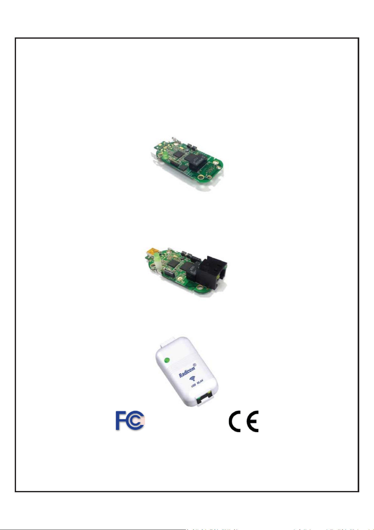
RW8300M Series (USB)
Universal USB/WiFi/LAN/BLE Adapter Module with Pin Header
RW8300NE Series (USB)
Universal USB/WiFi/LAN/BLE Adapter Module with
mini USB and RJ45 jack
RW8300E Series (USB)
Universal USB/WiFi/LAN/BLE Adapter Standalone
Apr 20, 2017

`
Table of Contents
Introduction to the RW8300 (USB-Device) Universal Adapter Products ····· 3
Features ································ ································ ······················ 3
RW8300 (USB) Universal Adapter Applications Summary ······················ 6
Model N a mi n g S y st e m ································ ································ ···· 7
Model & O r d e r i n g I n for m a t i o n ································ ························ 8
RW8300 (USB) General Information ································ ················· 10
RW8300M-x DIP Module Mechanical Diagram and Pin Assignments ········ 12
RW8300M-x-B1/B2 DIP Module Mechanical Diagram and Pin Assignments 13
RW8300NE-x Module Mechanical Diagram ································ ········· 14
RW8300NE-x-B1/B2 Module Mechanical Diagram ································ 1 5
RW8300E-x Standalone Product Mechanical Diagram ··························· 16
RW8300-MB1 Mechanical Diagram ································ ··················· 17
RW8300-MB2 Mechanical Diagram and Pin Assignments ······················· 18
RW8300-MB3 Mechanical Diagram and Pin Assignments ······················· 19
RW8300-MB5 Mechanical Diagram and Pin Assignments ······················· 20
Ethern et Port Connector Pin Definitions ································ ············· 21
RW8300 (USB) LED operation ································ ························· 21
Mini USB Type-B Connector Pinouts ································ ················· 22
RJ45 Ethernet Cable Description ································ ······················ 22
RW8300-MB1 Development Board Descriptions ································ ··· 23
RW8300-MB2 Development Board Descriptions ································ ··· 2 4
RW8300-MB3 Development Board Descriptions ································ ··· 25
RW8300-MB5 Development Board Descriptions ································ ··· 26
WPS/RESET Button on RW8300 (USB)································ ·············· 27
Check in g & U p g r a d i ng F i r m w a r e V e r s i o n ································ ·········· 28
Reset RW8300 (USB) to the Default ································ ··················· 30
RW8300 (USB) Universal Adapter Quick Set Up Guide for Various
Application ································ ································ ·················· 3 5
1. Sma l l e s t p o c k e t r o u t e r ································ ····························· 35
2. USB to LAN ································ ································ ·········· 37
3. Hot Spot Sharing ································ ································ ···· 3 9
4. LAN to WL AN ································ ································ ····· 4 2
5. USB to WLAN ································ ································ ······· 45
6. WLAN Bri dge ································ ································ ········ 49
EMC Guidance and Manufacturer’s Declaration ································ ·· 5 4
RW8300 Regulatory Domain Frequencies ································ ··········· 55
FC C , I C , a n d CE L abel L o c a t i o n a n d M o d u l e M o d e l I d e n t i f i c a t i o n ··········· 56
Limi t e d W a r r a n t y ································ ································ ········· 6 0
Contact i n g t h e Factory ································ ································ ··· 62
Information furnished by Radicom Research is believed to be accurate and reliable. However Radicom
Research assumes no responsibility for its use, or any infringement of patents or other rights of third
parties that may result from its use. Radicom Research reserves the right to change circuitry at any time
RW8300 (USB) Designer’s Guide Draft v.037 (04-20-17) 2
without notice. This document is subject to change without notice.

`
Introduction to the RW8300 (USB) Universal Adapter Products
Radicom Research’s RW8300 (USB) series is all new Wi-Fi/LAN with USB Host or USB
Device. It is the perfect networking center solution for embedded system to integrate Wi-Fi,
Ethernet, BLE, or USB into a single platform. The AIO (All-In-One) networking capability
provides many functions, such as single port router, Wi-Fi adapter, Ethernet adapter,
Hotspot, Wi-Fi Repeater or WLAN bridge, BLE single mode, BLE dual mode, and with
USB host capability for various applications.
It can turn any Ethernet LAN port to a WiFi hotspot or connect PC or Laptop into a WiFi
Wireless Access Point. Any WiFi Device such as iPhone, iPod, PDA, within range can
connect to Internet by sharing your RW8300 (USB) Access Point.
The RW8300 (USB) series is a full embedded system. It does not require CPU host when
using as single port router or hotspot mode. This versatile RW8300 (USB) series of
products offers easy integration for additional BLE single mode or dual mode module to
meet the specific system requirements.
For RW8300 (USB-Device), please see RW8300 (USB-Device) Designer’s Guide for details.
For RW8300 (Serial), please see RW8300 (Serial) Designer’s Guide for detail
Please note that RW8300 firmware for USB Host and USB Device are not compatible.
s.
Features
Wi-Fi
x WiFi AP/Client
x Router capability
x IEEE 802.11b/g/n compatible WLAN adapter
x WiFi USB adapter
x USB Ethernet adapter
x USB 1.1/2.0 and OTG (optional)
x 20MHz and 40MHz bandwidth transmission
x Operates in 2.4GHz Frequency Range
x Support WPS mode
x Backward compatible with 802.11b/g Devices while operating at 802.11n data rates
x Frame aggregation for increased MAC efficiency (A-MSDU, A-MPDU)
x Low latency immediate High-Throughput Block Acknowledgement (HT-BA)
x Long NAV for media reservation with CF-End for NAV release
x PHY-level spoofing to enhance legacy compatibility
x Built-in TCP/IP stack
x Channel management and co-existence
x Support Wake-On-WLAN via Magic Packet and Wake-up frame
x Transmit Opportunity (TXOP) Short Inter-Frame Spaces (SIFS) bursting for higher
multimedia bandwidth
x Short Guard Interval (400ns)
x DSSS with DBPSK and DQPSK, CCK modulation with long and short preamble
RW8300 (USB) Designer’s Guide Draft v.037 (04-20-17) 3

`
x Selectable digital transmit and receive FIR filters
x Support DHCP for LAN
x One Ethernet port
x Extended temperature: -40濎 to +85濎
x Support IEEE 802.11b/g/n compatible WLAN
x Support IEEE 802.11e QoS Enhancement (WMM)
x Support IEEE 802.11h TPC, Spectrum Measurement
x Support IEEE802.3 & IEEE802.3u
x Support IEEE802.3x full duplex flow control
x Support IEEE802.3az Energy efficiency
x Support IEEE 802.11i (WPA, WPA2, WEP). Security ~ Open, shared key, and
pair-wise key authentication services
x Support TLS mode
x Firmware upgradable
x FCC/IC/CE (pending)
x RoHS compliant
Bluetooth Low Energy (BLE-single mode)
x Bluetooth 4.0 single mode Compliant
x Supports Host and Client modes
x Integrated Bluetooth low energy stack including ATT, GATT, SMP, L2CAP, GAP
x TX Power: 4.0 dBm Max ~ RX Sensitivity: -92.5dBm Min
x Range: Up to 20 meters (line of sight)
x 12 digital PIOs, 3 analogue AIOs
x 10-bit ADC
2
x Serial Interface (UART / SPI / I
C)
x SPI for external flash
x 3 PWM modules
x Wake-up interrupt
x Watch Dog Timer
x On-board microprocessor, RAM and ROM
x On-board antenna
x Passthrough Data Mode
x AT Comm and s
x Extended temperature operating
x FCC/IC/CE
x RoHS compliant
Bluetooth Low Energy (BLE-dual mode)
x Fully qualified Bluetooth® v4.0 system
x Full-speed Bluetooth operation with full Piconet and Scatternet support
x Class 1 Bluetooth power level supported
x Dual-mode Bluetooth low energy radio
x 2Mbps and 3Mbps EDR support
x High-sensitivity Bluetooth receiver
x Wideband speech
x A-law, μ-law and linear voice data from Host
x A-law, μ-law, and CVSD voice over the air
x Voice interpolation for lost packets
x Rate mismatch correction
RW8300 (USB) Designer’s Guide Draft v.037 (04-20-17) 4

`
x PCM/I2S digital audio interface
x Fast AGC for enhanced dynamic range
x SBC encoding
x Fully integrated synthesizer requiring no external VCO varactor diode, resonator or
loop filter
x 3 Bluetooth low energy connections at the same time as basic rate A2DP
x Low-power selectable 1.2 to 3.6V I/O (Optional)
x High-speed UART port (up to 4Mbps)
x Supports IEEE 802.11® coexistence
x Digital demodulator for improved sensitivity and co-channel rejection
x Real time digitized RSSI available on HCI interface
x Extended Temperature Operation
x FCC/IC/CE
x RoHS compliant
RW8300 (USB) Designer’s Guide Draft v.037 (04-20-17) 5
`
,
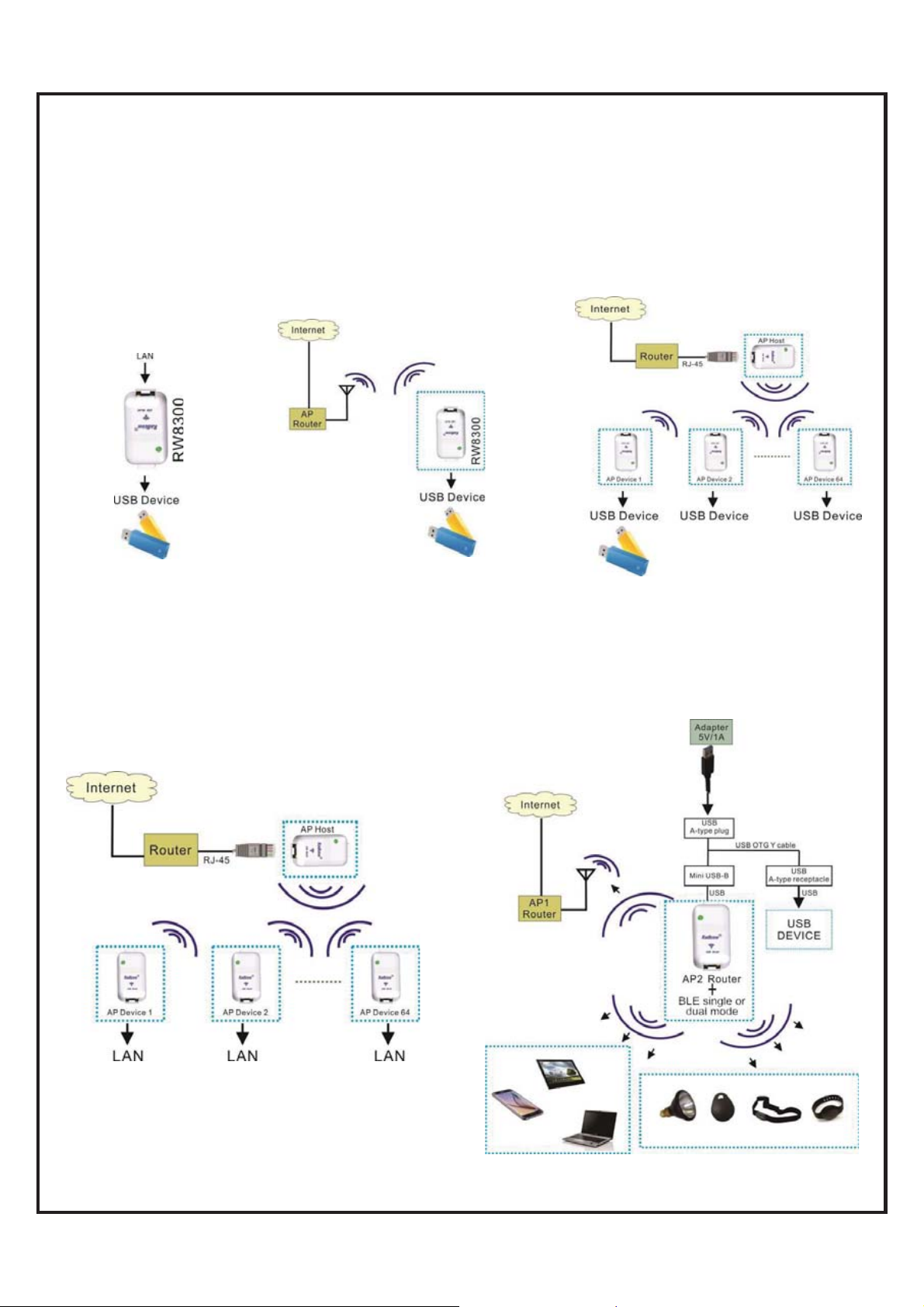
RW8300 (USB-Host) Universal Adapter Applications Summary
RW8300 (USB-Host) supported following applications:
LAN to USB Device
LAN to USB device
application.
Wi-Fi to USB Device
Wi-Fi to USB device
application.
Extend Wired LAN through
WiFi to reach USB Device
From RW8300 USB interface, USB devices
can simply connect and access to other LAN
through WiFi communication.
Extend Wired LAN through WiFi
from One LAN to the Other
From RW8300 LAN interface, computers can simply
connect and access to other LAN through WiFi
communication.
WiFi + LAN + Bluetooth
The RW8300 supported WiFi, LAN, and Bluetooth
applications. It can be an IOT gateway with Bluetooth
extended functions, such as Bluetooth remote control,
sensor
BLE wrist band, keyfob, or BLE lights.
RW8300 (USB) Designer’s Guide Draft v.037 (04-20-17) 6
`
Model Naming System
Product Series: RW8300 x – (x) – x – (x) – x
M: DIP module with pin headers
NE: Standalone module without enclosure
E: Standalone product with enclosure
Optional
B1: BLE single mode
B2: BLE dual mode
a: Embedded on-board antennas
c: U.FL connectors for external antennas
Optional
NL: no LAN
NW: no WLAN
D or (USB Device)
H or (USB Host)
HH or (2USB Host Ports)
S or (Serial)
SH or (Serial+ USB Host)
EVK Series: RW8300-MB x – x – (x) – (x) – (x)
1: MB1=RJ45, RS232, DB-9
2: MB2=MB1 + SPI, I2C, RS485, USBx2, BLE
3: MB3=MB2 + PoE, DC jack
5: MB5=MB3 + Modem (industrial)
S: Serial type
D: USB Device type
H: USB Host type
Optional for MB5
M: Modem
Optional for MB5
E: Enclosure
Optional for MB3/MB5
P: PoE (Power over Ethernet)
Available models:
RW8300-MB1-S: Serial type
RW8300-MB1-D: USB Device type
RW8300-MB2-H: USB Host type
RW8300-MB3-H: USB Host type
RW8300-MB3-H-P: USB Host type + PoE
RW8300-MB5-H: USB Host type
RW8300-MB5-H-M: USB Host type + Modem
RW8300-MB5-H-M-E: USB Host type + Modem + Enclosure
RW8300-MB5-H-E: USB Host type + Enclosure
RW8300-MB5-H-P: USB Host type +PoE
RW8300-MB5-H-M-P: USB Host type + Modem +PoE
RW8300-MB5-H-M-E-P: USB Host type + Modem + PoE + Enclosure
RW8300-MB5-H-E-P: USB Host type + PoE + Enclosure
RW8300 (USB) Designer’s Guide Draft v.037 (04-20-17) 7
`
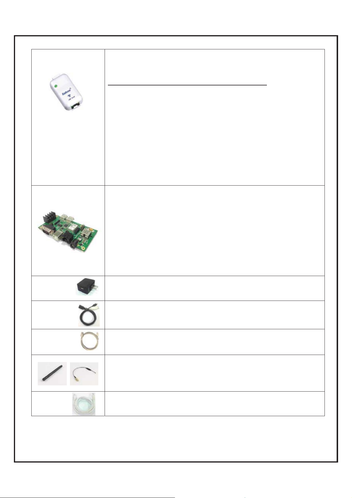
Model & Ordering Information
Model Number
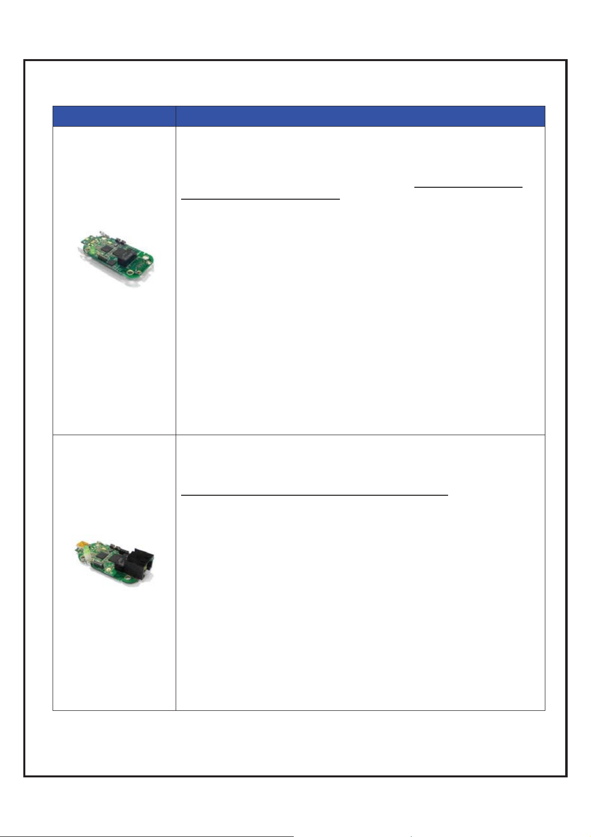
RW8300M Series
RW8300NE Series
Description
Universal Adapter (USB/WiFi/LAN/BLE) DIP Modules provide through hole
(DIP) pins for the USB and Ethernet pins that allow the Jacks to be placed
in preferred locations. Default 4M s-Flash, 8M as optional. This version of
RW8300M also supported to add BLE features. Note: firmware for USB
Host and Device are not compatible.
Models:
RW8300M-a:module with PIFA antenna
RW8300M-a-H: USB host DIP module with on-board antennas
RW8300M-a-NL:module with PIFA antenna, no LAN(w/o RJ45 jack
and 10/100 base transformer)
RW8300M-c: module with IPEX connector
RW8300M-c:-H USB host DIP module with U.FL antenna connectors
RW8300M-NW:module, no WLAN(w/o PIFA and IPEX)
RW8300M-B1-a-H: USB host + BLE single mode DIP module with on-board
antennas
RW8300M-B1-c-H: USB host + BLE single mode DIP module with U.FL
antenna connectors
RW8300M-B2-a-H: USB host + BLE dual mode DIP module with on-board
antennas
RW8300M-B2-c-H: USB host + BLE dual mode DIP module with U.FL antenna
connectors
RW8300M-B2-a-HH: 2 USB Host ports + BLE dual mode DIP module with
on-board antennas
RW8300M-B2-c-HH: 2 USB Host ports + BLE dual mode DIP module with
U.FL antenna connectors
Universal Adapter (USB/WiFi/LAN/BLE) Module with on board mini USB
and RJ45 jack that allow the flexibility of USB cable length. Default 4M
s-Flash, 8M as optional. This version of RW8300NE also supported to add
BLE single mode or dual mode.
Note: firmware for USB Host and Device are not compatible.
Models:
RW8300NE-a: Standalone module w/o enclosure, with PIFA antenna
RW8300NE-a-H: USB host module with on-board antennas
RW8300NE-a-NL: Standalone module w/o enclosure,with PIFA ,no
LAN(w/o RJ45 jack and 10/100 base transformer)
RW8300NE-c: Standalone module w/o enclosure with IPEX connector
RW8300NE-c-H: USB host module with U.FL antenna connectors
RW8300NE-c-NL: Standalone module w/o enclosure, with IPEX ,no LAN(w/o
RJ45 jack and 10/100 base transformer)
RW8300NE-NW: Standalone module w/o enclosure, w/o PIFA and IPEX
RW8300NE-B1-a-H: USB host + BLE single mode module with on-board
antennas
RW8300NE-B1-c-H: USB host + BLE single mode module with U.FL antenna
connectors
RW8300NE-B2-a-H: USB host + BLE dual mode module with on-board
antennas
RW8300NE-B2-c-H: USB host + BLE dual mode module with U.FL
antenna connectors
RW8300 (USB) Designer’s Guide Draft v.037 (04-20-17) 8
`
RW8300ESeries
Universal Adapter (USB/WiFi/LAN/BLE) Standalone in Plastic Enclosure
with mini USB and RJ45 jack. RW8300E-a is embedded with on-board
antennas and is optional to add BLE single mode or dual mode module in
the plastic enclosure. Default loaded 4M s-Flash, 8M as optional.
Note: firmware for USB Host and Device are not compatible.
Models:
RW8300E-a-H: antenna embedded USB- Host standalone
RW8300E-B1-a: Standalone product with enclosure, with BT 4.0(RB1083),
PIFA
RW8300E-B1-a-H: antenna embedded USB- Host standalone with BLE
single mode
RW8300E-B2-a: Standalone product with enclosure, with BT 4.0(RB2083),
PIFA
RW8300E-B2-a-H: antenna embedded USB-Host standalone with BLE dual
mode
RW8300E: Standalone product with enclosure, with PIFA,LAN, WLAN
RW8300E-NW: produce with enclosure, no WLAN(w/o PIFA, IPEX)
RW8300E-NL: produce with enclosure, with PIFA, no LAN(w/o RJ45 jack
and 10/100 base transformer)
RW8300-MBx-x-x
Power
Adapter
USB Y cable
USB to mini
USB cable
Antenna & Cable
USB Host Development Board for RW8300M module plug-in and easy
implementation. This development board series provides DB-9, USB, RJ-45,
RS485, PoE interface connectors and support Wi-Fi, Bluetooth, Modem
features for testing purpose.
Models:
RW8300-MB2-H: Host type
RW8300-MB3-H: Host type
RW8300-MB5-H: Host type (industrial)
RW8300-MB5-H-M: Host type + Modem (industrial)
RW8300-MB5-H-M-E: Host type + Modem + Enclosure (industrial)
RW8300-MB5-H-E: Host type + Enclosure (industrial)
Accessories- Power Adapter
Accessories- Y cable (Optional for OTG feature)
Accessories- USB to mini USB cable
Accessories- antenna and cable for models RW8300M-xx-xx-c &
RW8300NE-xx-xx-c.
ATN-2d-RP-SMA: Replacement antenna, 2.4GHz, 2dBi, RP-SMA plug,
and Omni-directional.
AC6i-RP-SMA: 6” U.FL. to RP-SMA jack antenna cable.
7’ RJ-45
cable
RW8300 (USB) Designer’s Guide Draft v.037 (04-20-17) 9
Accessories- 7’ RJ-45 cable
`
RW8300 (USB) General Information
WiFi Ratings @ 25° C
Parameter Min Typical Max Units
Operating Temperature RW8300 25 C°
Relative Humidity (non-condensing) 5 95
USB Voltage Requirement VDC
Current Consumption when WiFi_ON 370 mA
炴
Current Consumption when WiFi_OFF and
LAN connected
Current Consumption when WiFi_OFF and
LAN disconnected
Storage and transportation condition, in
range of °C and % R.H.
Operating temperature, humidity and
atmospheric pressure range
Highest operation altitude
IP Classification protection against harmful
ingress of water and particulate matter.
Ingress Protection Rating 21
Expected service life
206 mA
173 mA
BLE single mode Ratings @ 25° C
ġ Minimum Typical Maximum Unit
Operation voltage 2.35 3.3 3.6 V
Output Power 4.0 dBm
Sensitivity -92.5 dBm
Current Consumption *
Dormant mode 600 nA
Deep Sleep mode
Idle mode
RX/TX active
* The Current Consumption is code dependent. Bluetooth functions and characteristics will vary depending on
the application firmware that is loaded into the RW8300xx-xx-B1-x module. The standard code is for BLE data
applications and Deep Sleep or Dormant mode is not available. Using any I/O (output) will draw more current
and change the overall current consumption.
1.91 mA
2.24 mA
5uA
RW8300 (USB) Designer’s Guide Draft v.037 (04-20-17) 10
`
BLE dual mode Ratings @ 25° C
ġ Minimum Typical Maximum Unit
Operation voltage 3.1 3.3 3.6 V
Output Power 4.0 dBm
Sensitivity -84 dBm
Current Consumption *
Host (Master) Idle mode
Client (Slave) Idle mode
12.1 15.2 18.5 mA
12.1 15.2 25.2 mA
RB8762 FCC ID:K7T-RB8762
Physical Description
RW8300M-H-a/c
Size & Weight:
RW8300M-H-(B1/B2)-a/c
Size & Weight:
RW8300NE-H-a/c
Size & Weight:
RW8300NE-H-(B1/B2)-a/c
Size & Weight:
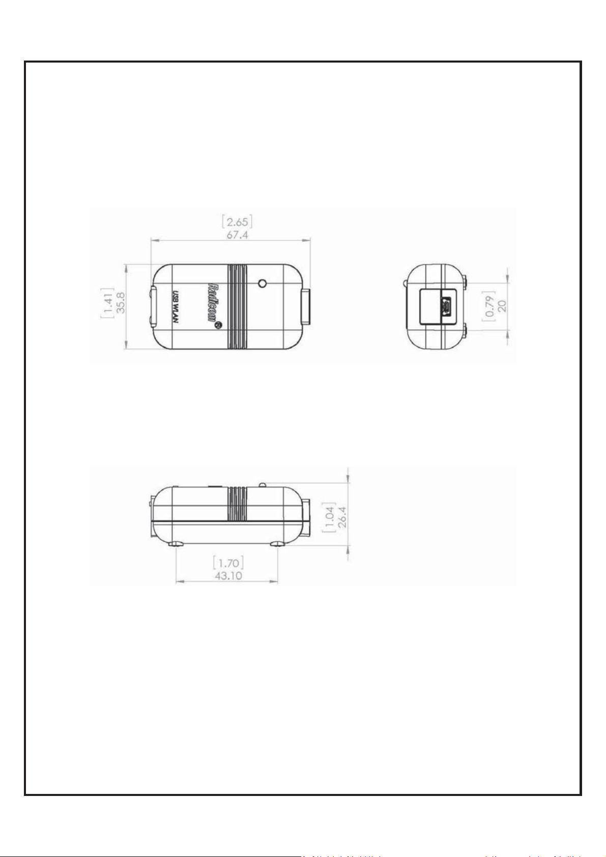
RW8300E-H-a
Size & Weight:
RW8300E-H-(B1/B2)-a
Size & Weight:
2.5” x 1.2” x 0.5” (62.7 x 29.3 x 13.4mm)
7.3g
2.5” x 1.2” x 0.8” (62.7 x 29.3 x 19.2mm)
9.9g
2.7” x 1.4” x 1.0” (67.4 x 35.8 x 26.4mm)
35.6g
2.7” x 1.4” x 1.0” (67.4 x 35.8 x 26.4mm)
g
RW8300 (USB) Designer’s Guide Draft v.037 (04-20-17) 11
`
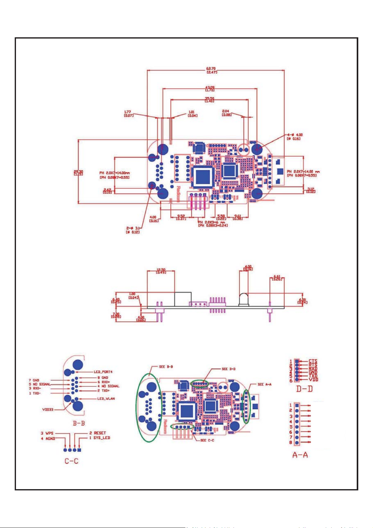
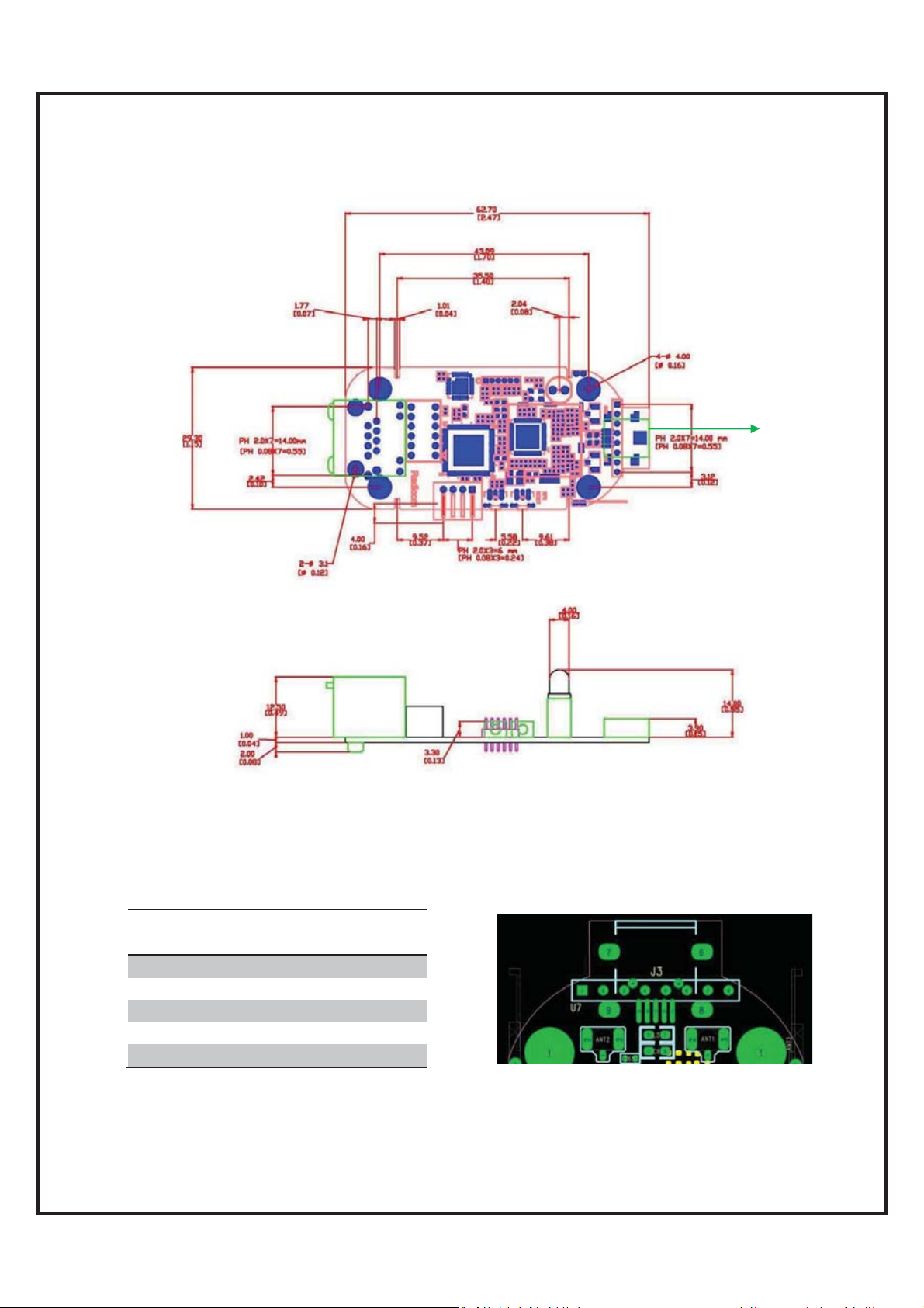
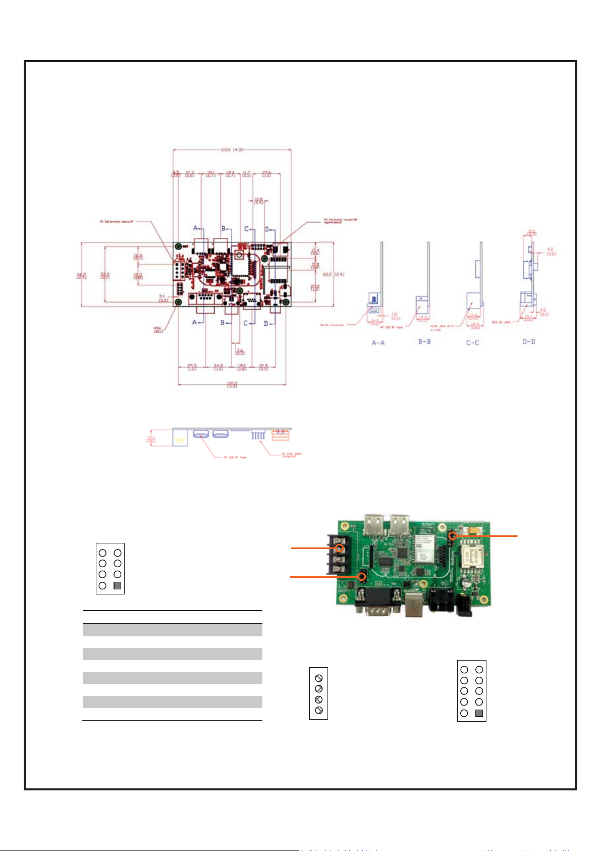
RW8300M-x DIP Module Mechanical Diagram & Pin Assignments
Top V iew:
Unit: mm[inch]
Side View:
Pin Assignments:
(LAN port)
(LAN port)
(Debug port)
(Interface port)
(USB port)
(Debug port)
GND
AGND
GND
ID
DM
DP
SYS_USB
USB_VCC
(USB port)
(Interface port)
RW8300 (USB) Designer’s Guide Draft v.037 (04-20-17) 12

`
RW8300M-x-B1/B2 DIP Module Mechanical Diagram &
Pin Assignments
RW8300 (USB) Designer’s Guide Draft v.037 (04-20-17) 13
`
Top V iew:
Unit: mm[inch]
RW8300NE-x Module Mechanical Diagram
J3
Side View:
Pin Assignments:
J3
(USB Connector)
PIN 1 USB_VCC
PIN 2 DM
PIN 3 DP
PIN 4 AGND
PIN 5 AGND
J3
USB_MODE
RW8300 (USB) Designer’s Guide Draft v.037 (04-20-17) 14

`
RW8300NE-x-B1/B2 Module Mechanical Diagram
RW8300 (USB) Designer’s Guide Draft v.037 (04-20-17) 15
`
RW8300E-x Standalone Product Mechanical Diagram
Top V iew:
Unit: mm[inch]
Side View:
RW8300 (USB) Designer’s Guide Draft v.037 (04-20-17) 16
`
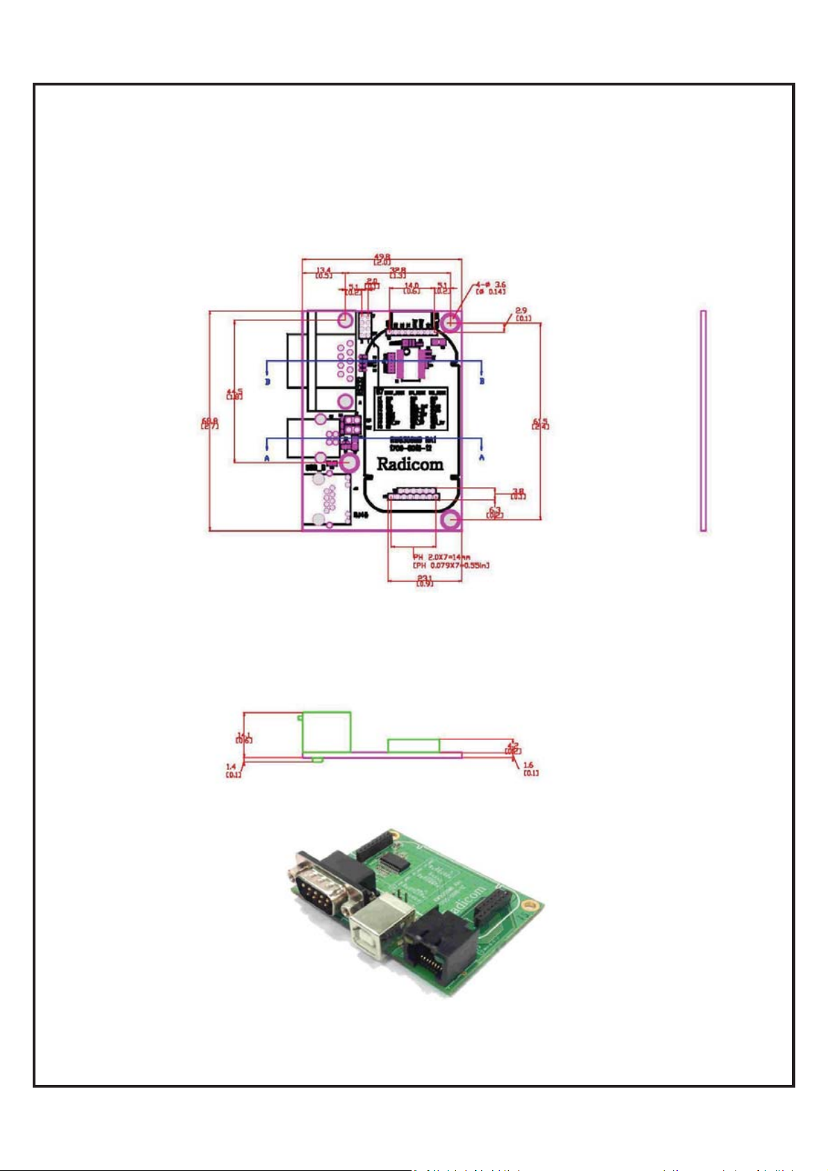
Top V iew:
Unit: mm[inch]
RW8300-MB1 Mechanical Diagram
Side View:
RW8300 (USB) Designer’s Guide Draft v.037 (04-20-17) 17
`
View:
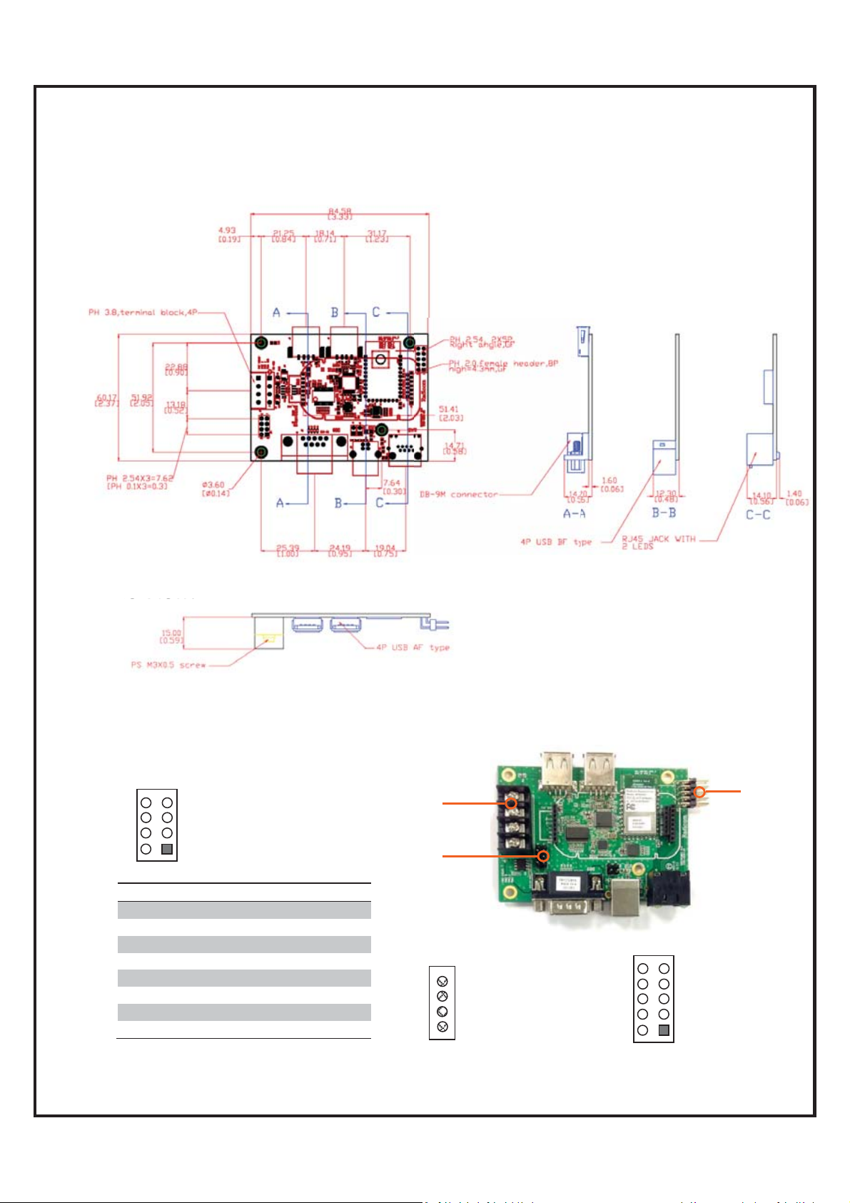
RW8300-MB2 Mechanical Diagram and Pin Assignments
Top V iew:
Unit: mm[inch]
Side View:
Pin Assignments:
J14
8
6
4
2
J14 I2C Mode SPI Mode UART Mode
P1 GND GND GND
P2 NC NC NC
P3 GPIO_6 SSEL_OUT RXD
P4 GPIO_5 SCLK_IN TXD
P5 SCL MISO_OUT RTS
P6 SDA MOSI_IN CTS
P7 VDD_5V VDD_5V VDD_5V
P8 NC NC NC
7
5
3
1
J13
J14
J13 RS-485 connector
4 GND
3 A
2 B
1 VDD 5V
PIN1_GND
GPIO_10 8
GPIO_8 6
GPIO_6 4
GPIO_1 2
J19 Reserved GPIOs
10
9 PIN2_GPIO_11
7 GPIO_9
5 GPIO_7
3 GPIO_0
1 VDD 5V
J19
RW8300 (USB) Designer’s Guide Draft v.037 (04-20-17) 18
`
RW8300-MB3 Mechanical Diagram and Pin Assignments
Top V iew:
Unit: mm[inch]
Side View:
Pin Assignments:
J14
8
6
4
2
J14 I2C Mode SPI Mode UART Mode
P1 GND GND GND
P2 NC NC NC
P3 GPIO_6 SSEL_OUT RXD
P4 GPIO_5 SCLK_IN TXD
P5 SCL MISO_OUT RTS
P6 SDA MOSI_IN CTS
P7 VDD_5V VDD_5V VDD_5V
P8 NC NC NC
7
5
3
1
J13
J14
J13 RS-485 connector
4 GND
3 A
2 B
1 VDD 5V
PIN1_GND
GPIO_10 8
GPIO_8 6
GPIO_6 4
GPIO_1 2
J19 Reserved GPIOs
10
9 PIN2_GPIO_11
7 GPIO_9
5 GPIO_7
3 GPIO_0
1 VDD 5V
J19
RW8300 (USB) Designer’s Guide Draft v.037 (04-20-17) 19

`
RW8300-MB5 Mechanical Diagram and Pin Assignments
RW8300 (USB) Designer’s Guide Draft v.037 (04-20-17) 20

`
Ethernet Port Connector Pin Definitions
Standard RJ45 10/100 BASE-T Port
An RJ-45 connector is used for Ethernet twisted pair links. The RJ-45 connector has
8-pins, and may also be referred to as an 8-pin Modular Connector. A male RJ-45 plug
is mounted on each end of the twisted pair cable. A female RJ-45 Jack or Receptacle is
integrated into the Ethernet hub or NIC.
Ethernet Connector (J1)
Ethernet Connector LED Operation
(TBD)
RW8300 (USB) LED Operation
When the RW8300 (USB) is power ON, the LED indicator will be blinking in about 10
seconds, it indicates the RW8300 (USB) has finished booting up.
RW8300 (USB) Designer’s Guide Draft v.037 (04-20-17) 21

`
Mini USB Type-B Connector Pinouts
Pin Name Description Color
1 VCC +5V Red
2 D- Data - White
3 D+ Data + Green
OTG Identification:
4ID
5 GND Ground Black
x Host: connected to ground
x Slave: not connected
Not
connected
RJ45 Ethernet Cable Description
The following table shows the RJ-45 connector pin assignments for Ethernet Cable.
PHY data rate is 100Mbps.
CAT.5e Ethernet Cable
RJ-45 Plug
(8 pin)
Contact 10/100 Base-T Signal
1 TD+ (Transmit Data)
2 TD- (Transmit Data)
3 RD+ (Receive Data)
4Not used
5Not used
6 RD- (Receive Data)
7 Not Used
8 Not Used
RW8300 (USB) Designer’s Guide Draft v.037 (04-20-17) 22

`
RW8300-MB1 Development Board Descriptions
The RW8300-MB1 Development Board is designed for RW8300M module easy testing
and function verification.
Serial interface
header
DB-9 connector
RW8300M module
location
USB connector
Operations:
1. Plug in RW8300M-x module onto the RW8300-MB1.
2. Connect RJ45 Ethernet cable to RW8300-MB1 RJ45 JACK.
3. Connect a serial cable between RW8300-MB1 Serial connector and PC serial
4. Connect USB cable to RW8300-MB1 USB connector for power supply.
5. Wait for LEDs on and it is ready for evaluation.
RJ-45 interface
header
RJ-45 Jack
USB interface header
reserved for RW8300 (USB) only
port.
RW8300 (USB) Designer’s Guide Draft v.037 (04-20-17) 23

`
RW8300-MB2 Development Board Descriptions
The RW8300-MB2 Development Board is designed for RW8300M-H-x or
RW8300M-HH-x module easy testing and function verification.
USB connector for
External memory or camera
Serial pin header for
RW8300M Module
plug-in
RS-485 connector
RW8300M WiFi module
DB-9 connector
USB connector
Operations:
1. Plug in RW8300M module onto the RW8300-MB2.
2.
USB interface header
RB2001 BLE module
GPIOs reserved for RW8300
(USB-Device) only
RJ-45 pin header for
RW8300M Module plug-in
RJ-45 Jack
RW8300 (USB) Designer’s Guide Draft v.037 (04-20-17) 24

`
The RW8300-MB3 Development Board is designed for RW8300M-H-x or
RW8300M-HH-x module easy testing and function verification.
RS-485 connector
DB-9 connector
RW8300-MB3 Development Board Descriptions
USB connector for
External memory or camera
Serial pin header for
RW8300M Module
plug-in
RW8300M WiFi module
RB2001 BLE module
USB connector
Operations:
1. Plug in RW8300M module onto the RW8300-MB3.
2.
USB interface header
GPIO reserved for RW8300
(USB-Device) only
RJ-45 pin header for
RW8300M Module plug-in
DC Jack (24V ~ 60V)
RJ-45 Jack (PoE supported)
RW8300 (USB) Designer’s Guide Draft v.037 (04-20-17) 25

`
RW8300-MB5 Development Board Descriptions
The RW8300-MB5 Development Board is designed for RW8300M-H-x or
RW8300M-HH-x module easy testing and function verification.
RW8300 (USB) Designer’s Guide Draft v.037 (04-20-17) 26

`
WPS/RESET Button on RW8300 (USB)
1. How to use the RESET MFB (multi-functional button)
Reset (Reboot)/ Reset to Factory Default Setting
1.1 Reset (Reboot): Press and hold the RESET button for 5~8 seconds then
release, RW8300 (USB) will reboot.
1.2 Reset to default: Press and hold the RESET button for 12 seconds then release,
RW8300 (USB) will reboot and reset to factory default setting.
2. WPS button (* this function only available under AP mode, NOT available under
Station mode)
2.1 Press RW8300 (USB) WPS button to enter WPS mode and complete wireless
settings.
2.2 Make sure the PC or smart phone is also in the WPS mode (please refer to your
PC or smart phone manual how to enter WPS mode).
2.3 RW8300 (USB) and Device will automatically complete the wireless settings.
2.4 Once WPS settings complete, PC or smart phone will connect to RW8300 (USB)
AP.
WPS
Reboot/Reset to default
RW8300 (USB) Designer’s Guide Draft v.037 (04-20-17) 27

`
Checking & Upgrading Firmware Version
Connect the RJ45 cable and mini USB cable to RW8300.
Please make sure the RW8300 is connected to Webserver.
Open a browser and type the default gateway address (192.168.1.254).
Go to Management → Status page to check current firmware version.
Go to Management → Upgrade Firmware page for upgrading firmware.
1. Click Browse to select the upgrading firmware location, and click Upload.
RW8300 (USB) Designer’s Guide Draft v.037 (04-20-17) 28

`
2. It will take approximately 95 seconds to complete the upgrading.
Warning: "DO NOT power down or interrupt the upgrading process."
3. Press and hold the RESET button on RW8300 for 12 seconds then release,
RW8300 will reboot and reset to factory default setting. Upgrading firmware is now
complete.
RW8300 (USB) Designer’s Guide Draft v.037 (04-20-17) 29

`
Reset RW8300 (USB) to the Default
Reset to factory default setup procedures:
1. Plug-in RJ45 cable to RW8300 (USB) and the other side to the PC
2. Plug-in USB cable to RW8300 (USB) and the other side to the PC
3. Waiting for initiation (might takes up to 3min)
4. Confirm the default gateway setting (ex. 192.168.1.254):
Below is an example for Windows 7
Go to Start\Control Panel\Network and Internet\Network Connections
Double Click the RW8300 (USB) Network to find out the IPv4 default gateway IP address.
RW8300 (USB) Designer’s Guide Draft v.037 (04-20-17) 30
`
烉
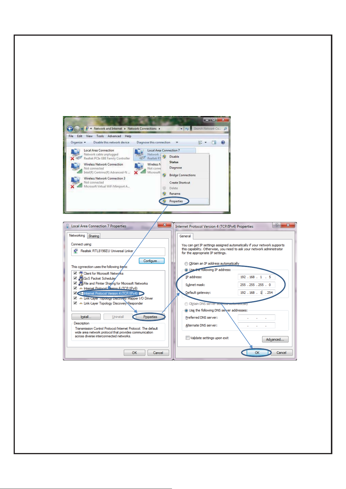
5. If you can’t find the default gateway web page (ex. 192.168.1.254), please refer to
following procedures to manually set up the parameters. You can skip the following
if the default gateway web page is working.
Go to Start\Control Panel\Network and Internet\Network Connections
Right click the RW8300 (USB) Network and select Properties\Internet Protocol
Version 4 (TCP/IPv4)\Properties
Appropriate IP settings烉
IP address烉192.168.1.2/253
Subnet mask烉255.255.255.0
Default gateway烉192.168.1.254
RW8300 (USB) Designer’s Guide Draft v.037 (04-20-17) 31

`
6. Reset the Network烉
Disable the RW8300 (USB) Network
Enable RW8300 (USB) Network
7. Open a browser and type the default gateway address (ex. 192.168.1/0.254)
Go to Management\Save/Load Setting, Click Reset
8. Waiting 40sec to reboot
RW8300 (USB) Designer’s Guide Draft v.037 (04-20-17) 32

`
9. Go to Start\Control Panel\Network and Internet\Network Connections
Change RW8300 (USB) Network setting back to original setting (DHCP IP and
DHCP DNS or original ISP provided default setting. This is to avoid affecting this PC
connectivity to other Networks.
RW8300 (USB) Designer’s Guide Draft v.037 (04-20-17) 33

`
10. Reset the Network烉
Disable RW8300 (USB) Network
Enable RW8300 (USB) Network
11. Unplug the RJ45 cable between RW8300 (USB) and PC.
12. RW8300 (USB) reset is now complete.
13. For other settings, please refer to “RW8300 Reference Guide for Network
Setting.pdf”.
RW8300 (USB) Designer’s Guide Draft v.037 (04-20-17) 34

`
RW8300 (USB) Universal Adapter Quick Set Up Guide
For Various Applications
Application Quick Setup Procedures.
Please restore to the default setting before changing to other applications (please refer
to “Reset RW8300 (USB) to the Default”).
For other settings, please refer to “RW8300 Reference Guide for Network Setting.pdf”.
1. Smallest router
The RW8300 (USB) is easy to carry and set up. Connect an Ethernet cable and
RW8300 (USB) will create a secure wireless network for your Devices.
Set up procedures:
1.1 Connect an Ethernet cable to RW8300 (USB) and wait for 1minute for initiation.
User will see “RW8300 11n AP” from the WiFi list.
1.2 Click to connect to SSID烉RW8300 11n AP (Default is no encryption炸
RW8300 (USB) Designer’s Guide Draft v.037 (04-20-17) 35

`
1.3 Press Windows + R or click “Start” -> “Run”. Input “cmd” to open the
Administrator.
1.4 Input “ipconfig /all”, then press Enter.
Find the default gateway IP address.
1.5 Open a web browser and you should be able to surf the internet.
RW8300 (USB) Designer’s Guide Draft v.037 (04-20-17) 36

`
2. USB to LAN
Ultrabooks, such as ZENBOOK, MacBook Air, and MacBook Pro, usually lack a RJ-45
port, and users can simply connect a network cable to ultrabooks via USB port to
provide a stable online access anywhere.
Set up procedures:
2.1 Connect a USB cable between your Ultrabook and RW8300 (USB). And
connect an Ethernet cable to RW8300 (USB).
2.2 Ultrabook will auto detect the hardware and add a new CD Drive into your
computer. Driver installation might take few minutes.
RW8300 (USB) Designer’s Guide Draft v.037 (04-20-17) 37

`
2.3 After driver installation complete, the Device will appear in the Device Manager.
2.4 Open a web browser and you should be able to surf the internet.
RW8300 (USB) Designer’s Guide Draft v.037 (04-20-17) 38

`
3. Hot Spot Sharing
The RW8300 (USB) supported hot spot mode. Connect a mini USB cable to power on,
and it can share a single account on multiple Devices, such as notebooks,
smartphones, tablets, etc.
Set up procedures:
3.1 Connect an Ethernet cable between your computer and RW8300 (USB) for hot
spot setting.
3.2 After your computer connected to RW8300 11n AP, please open a web browser
and input “http://192.168.1.254” (default gateway) in the address bar.
RW8300 (USB) Designer’s Guide Draft v.037 (04-20-17) 39

`
3.3 Click “Operation Mode” and choose “Wireless ISP”. Click “Apply Change”.
Note: If the operation mode is already Wireless ISP, no need to click “apply change”.
Otherwise, the internet access might occur error. Troubleshooting is to disconnect the
“RW8300 11n AP”, then connect again.
3.4 Click “Site survey” under “Wireless” directory to see current available SSID.
Select the correct AP and click “Next”.
RW8300 (USB) Designer’s Guide Draft v.037 (04-20-17) 40

`
3.5 Input the Pre-Shared Key and click “Connect”.
3.6 After connect successfully, please click “Reboot Now”. Disconnect the hot spot,
then connect again to activate. Now, the hot spot is available.
RW8300 (USB) Designer’s Guide Draft v.037 (04-20-17) 41
`
4. LAN to WLAN
The RW8300 (USB) is perfect for your desktops, which usually lack Wi-Fi capabilities.
Simply connect an Ethernet cable to your desktops to stay connected.
Set up procedures:
4.1 Connect an Ethernet cable between your computer and RW8300 (USB) for
WLAN setting.
4.2 After your computer connected to RW8300 11n AP, please open a web
browser and input “http://192.168.1.254” (default gateway) in the address bar.
RW8300 (USB) Designer’s Guide Draft v.037 (04-20-17) 42

`
4.3 Click “Operation Mode” and choose “Wireless ISP”. Click “Apply Change”.
Note: If the operation mode is already Wireless ISP, no need to click “apply
change”. Otherwise, the internet access might occur error. Troubleshooting is to
disconnect the “RW8300 11n AP”, then connect again.
4.4 Click “Site survey” under “Wireless” directory to see current available SSID.
Select the correct AP and click “Next”.
RW8300 (USB) Designer’s Guide Draft v.037 (04-20-17) 43

`
4.5 Input the Pre-Shared Key and click “Connect”.
After connect successfully, please click “Reboot Now”. Disconnect the hot spot,
4.6
then connect again to activate. Now, the WLAN is available.
RW8300 (USB) Designer’s Guide Draft v.037 (04-20-17) 44

`
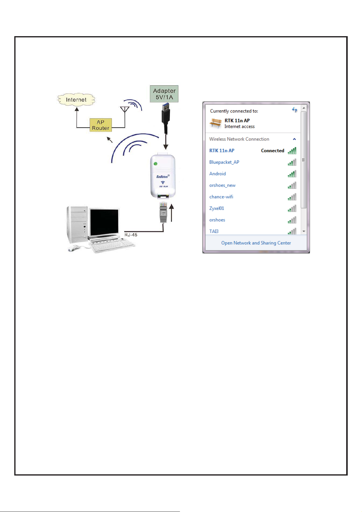
5. USB to WLAN
The RW8300 (USB) is easy for desktops to create a wireless network. Simply connect
an USB cable and RW8300 (USB) will create a wireless secure network access to
your desktops.
Set up procedures:
5.1 Connect a USB cable between your computer and RW8300 (USB).
5.2 Computer will auto detect the hardware and add a new CD Drive into your
computer. Driver installation might take few minutes.
RW8300 (USB) Designer’s Guide Draft v.037 (04-20-17) 45

`
5.3 After driver installation complete, the Device will appear in the Device
Manager.
5.4 Press Windows + R or click “Start” -> “Run”. Input “cmd” to open the
Administrator.
Input “ipconfig /all”, then press Enter. Find the default gateway IP address.
5.5
RW8300 (USB) Designer’s Guide Draft v.037 (04-20-17) 46

`
5.6 After your computer connected to RW8300 11n AP, please open a web browser and
input “http://192.168.1.254” (default gateway) in the address bar.
5.7 Click “Operation Mode” and choose “Wireless ISP”. Click “Apply Change”.
Note: If the operation mode is already Wireless ISP, no need to click “apply change”.
Otherwise, the internet access might occur error. Troubleshooting is to disconnect the
“RW8300 11n AP”, then connect again.
5.8
Click “Site survey” under “Wireless” directory to see current available SSID.
Select the correct AP and click “Next”.
RW8300 (USB) Designer’s Guide Draft v.037 (04-20-17) 47

`
5.9 Input the Pre-Shared Key and click “Connect”.
After connect successfully, please click “Reboot Now”. Disconnect the hot spot,
5.10
then connect again to activate. Now, the WLAN is available.
RW8300 (USB) Designer’s Guide Draft v.037 (04-20-17) 48

`
6. WLAN Bridge
The RW8300 (USB) supported WLAN bridge mode, which can share a single account on
multiple subnet. All Devices are able to connect to the Internet.
Set up procedures:
6.1 Connect an Ethernet cable to RW8300 (USB) and wait for 1minute for initiation.
User will see “RW8300 11n AP” from the WiFi list.
6.2 Click to connect to SSID烉RW8300 11n AP (Default is no encryption炸
RW8300 (USB) Designer’s Guide Draft v.037 (04-20-17) 49

`
6.3 Press Windows + R or click “Start” -> “Run”. Input “cmd” to open the
Administrator.
6.4 Input “ipconfig /all”, then press Enter.
Find the default gateway IP address.
6.5 Log into Web GUI (Router mode)
After your computer obtained an IP address from wireless router, please open a
web browser, and input the IP address of the Default Gateway in address bar, and
the following message should be shown. Please click “admin” to login the RW8300
(USB).
RW8300 (USB) Designer’s Guide Draft v.037 (04-20-17) 50

`
6.6 Click “Operation Mode” and choose “Bridge”. Click “Apply Change”.
Note: If the operation mode is already Wireless ISP, no need to click “apply
change”. Otherwise, the internet access might occur error. Troubleshooting is
to disconnect the “RW8300 11n AP”, then connect again.
6.7 Please wait 25 seconds to complete the setting.
6.8 Click Network Settings > LAN Interface
6.8.1 Select “Disabled” from DHCP pull-down list.
6.8.2 Click “Apply Changes”.
RW8300 (USB) Designer’s Guide Draft v.037 (04-20-17) 51

`
6.8.3 Reboot Now
6.9 Please wait 25 seconds to complete the setting.
Note: If you still can’t use the Internet till now, please power cycle RW8300
(USB).
RW8300 (USB) Designer’s Guide Draft v.037 (04-20-17) 52

`
6.10 Open a web browser and you should be able to surf the internet. This AP now
is also available for all other mobile Devices to connect.
RW8300 (USB) Designer’s Guide Draft v.037 (04-20-17) 53

`
EMC Guidance and Manufacturer’s Declaration
RW8300 (USB) Designer’s Guide Draft v.037 (04-20-17) 54

`
RW8300 Regulatory Domain Frequencies
The channel identifiers, channel center frequencies, and regulatory domains of each
22-MHz-wide channel are shown in following table.
Model:
RW8300
Family
1 2412
2 2417
3 2422
4 2427
5 2432
6 2437
7 2442
8 2447
9 2452
10 2457
11 2462
12 2467
Frequency
(MHZ)
Regulatory Domains
Japan ETSI
North
America
Israel
France
Outdoor
Mexico
13 2472
14 2484
RW8300 (USB) Designer’s Guide Draft v.037 (04-20-17) 55

`
FCC, IC, and CE Label Location and Module Model
Identification
The RW8300 module family is FCC Part 15 and IC (Industry Canada) certified. The RW8300 is
also CE marked. The modules are labeled with the appropriate RW8300 module model number
and FCC Part 15 ID, IC registration number and CE mark. The label can be found on top of the
metal shielding on the RW8300 Module.
Important Regulatory Compliance and User Information
The final product with the modules installed needs to be tested for FCC Part 15, IC
(Industry Canada) CE, EMI/RFI compliance. Radicom certification documentation will
help streamline the final product approval process. Contact Radicom for more
information. To maintain compliance in the finished product, carefully follow guidelines
in this section.
This device is intended only for OEM integrators under the following conditions:
1) The antenna must be installed such that 20 cm is maintained between the
antenna and users. For laptop installations, the antenna must be installed to ensure that
the proper spacing is maintained in the event the users places the device in their lap
during use.
2) The transmitter module may not be co-located with any other transmitter or
antenna. As long as the two conditions above are met, further transmitter testing will not
be required. However, the OEM integrator is still responsible for testing their end product
for any additional compliance requirements required with the module installed (for
example, digital device emissions, PC peripheral requirements, etc).
IMPORTANT NOTE: In the event that these conditions can not be met (for example
certain laptop configurations or co-location with another transmitter), then the FCC
authorization is no longer considered valid and the FCC ID can not be used on the final
product. In these circumstances, the OEM integrator will be responsible for re-evaluating
RW8300 (USB) Designer’s Guide Draft v.037 (04-20-17) 56

`
the end product (including the transmitter) and obtaining a separate FCC & IC authorization.
Contains FCC ID: K7T-RW8300 Contains IC: 2377A-RW8300
Labeling Requirements
To maintain compliance, the end product hosting the RW8300 module must be properly
labeled to identify that this module is installed. This transmitter module is authorized
only when used in devices where the antenna is installed such that 20 cm is maintained
between the antenna and users. The final end product must have a label located in a
visible area with the following information:
The XXXXXXX reflects the correct model installed into the host equipment: The
models are RW8300-a, or RW8300-c.
The label shall be securely affixed to a permanently attached part of the device, in a
location where it is visible or easily accessible to the user, and shall not be readily
detachable. The label shall be sufficiently durable to remain fully legible and intact on the
device in all normal conditions of use throughout the device’s expected lifetime. These
requirements may be met either by a separate label or nameplate permanently attached to
the device or by permanently imprinting or impressing the label directly onto the device.
The label text shall be legible without the aid of magnification, but is not required to be
larger than 8-point font size.
End User Information: This equipment complies with FCC radiation exposure
limits set forth for an uncontrolled environment. End users must follow the specific
operating instructions for satisfying RF Exposure compliance. The end user should NOT
be provided any instructions on how to remove or install the device. The user’s manual
for end users must include the following information in a prominent location.
RW8300 (USB) Designer’s Guide Draft v.037 (04-20-17) 57

FCC RF Radiation Exposure Statement
IMPORTANT NOTE: To comply with the FCC RF exposure compliance requirements, the
antenna used on this transmitter must be installed to provide a separation of at least 20 cm from all
persons and must not be co-located or operating in conjunction with any antenna or transmitter.
This device contains a low power transmitter. When this device is operational, use only with the
supplied, or recommended antenna. Unauthorized antenna, modification, or attachments could
damage the transmitter and may violate FCC regulations. Changes or modifications not expressly
approved by the manufacturer or party responsible for compliance could void the user’s authority
to operate the equipment.
FCC Interference Statement
This device complies with Part 15 of the FCC Rules. Operation is subject to the following
conditions:
(1) This device may not cause harmful interference
(2) This device must accept any interference received, including interference
that may cause undesired operation.
This equipment has been tested and found to comply with the limits for a Class B digital
device, pursuant to Part 15 of the FCC Rules. These limits are designed to provide reasonable
protection against harmful interference in a residential installation.
This equipment generates and radiates radio frequency energy and, if not installed and
used in accordance with the instructions, may cause harmful interference to radio communications.
There is no guarantee that interference will not occur in a particular installation. If this equipment
does cause harmful interference to radio or television reception, which can be determined by
turning the equipment off and on, the user is encouraged to try to correct the interference by one of
the following measures:
● Reorient or relocate the receiving antenna.
● Increase the separation between the equipment and receiver.
● Connect the equipment into an outlet on a circuit different from that to which the receiver is
connected.
● Consult the dealer or an experienced radio/TV technician for assistance.
IC (Industry Canada) Statement:
“This device complies with Industry Canada license-exempt RSS standard(s). Operation is subject
to the following two conditions: (1) this device may not cause interference, and (2) this device must
accept any interference, including interference that may cause undesired operation of the device”
Le present appareil est conforme aux CNR d’Industrie Canada applicables aux appareils radio
exempts de license. L’exploitation est autorisee aux deux conditions suivantes: (1) l’appareil ne doit
pas produire de brouillage, et (2) l’utilisateur de l’appareil doit acceptor tout brouillage
radioelectrique subi, meme si le brouillage est susceptible d’en compromettre le fonctionnement.
Enonce d’exposition au rayonnement radioelectrique. Cet appareil est conforme aux limites
d’exposition au rayonnement radioelectrique stipulees par la FCC pour une utilisation dans un
environnement non controle. Cet appareil doit etre installe et utilise en respectant une distance
minimale de 20 centimetres entre l’element rayonnant et votre corps. Pour une utilisation mobile ou
portee sur le corps, cet appareil a ete teste et certifie conforme aux directives de la FCC relatives a
l’exposition au rayonnement radioelectrique lorsqu’il est utilise avec la
Europe – R&TT E Compliance Statement:
Hereby, Radicom Research Inc. declares that this equipment complies with the essential
requirements and other relevant provisions of DIRECTIVE 1999/5/CE OF THE EUROPEAN
PARLIAMENT AND THE COUNCIL of March 9, 1999 on radio equipment and telecommunication
terminal Equipment and the mutual recognition of their conformity (R&TTE).
RW8300 (USB) Designer’s Guide Draft v.037 (04-20-17) 58
`
CE Declaration of Conformity
For the following equipment:
Radicom Research Inc. WiFi USB Modem Module
Model(s): RW8300-a, RW8300-c
is herewith confirmed to comply with the requirements set out in the Council
(European parliament) Directive on the Approximation of the Laws of the
Member States relating to Electromagnetic Compatibility of Radio and Telecom device
(1999/5/CE). For the evaluation regarding this Directive, the following
standards were applied:
EN 300 328 V1.8.1, EN 301 489-1 V1.9.2, EN 301 489-17 V2.1.1,
EN 61000-3-2:2006+A2:2009, EN 61000-3-3:2008,
EN 60950-1:2006+A11:2009+A1:2010+A12:2011, EN 62311:2008
This equipment is marked with the
community.
France – 2.4GHz for Metropolitan France:
In all Metropolitan departments, wireless LAN frequencies can be used under the
following conditions, either for public or private use:
x Indoor use: maximum power (EIRP*) of 100 mW for the entire 2400-2483.5 MHz
frequency band
x Outdoor use: maximum power (EIRP*) of 100 mW for the 2400-2454 MHz band
and with maximum power (EIRP*) of 10 mW for the 2454-2483 MHz band
Caution: Exposure to Radio Frequency Radiation.
To comply with RF exposure compliance requirements, for mobile configurations, a
separation distance of at least 20 cm must be maintained between the antenna of this
device and all persons.
and can be used throughout the European
RW8300 (USB) Designer’s Guide Draft v.037 (04-20-17) 59

`
Limited Warranty
Warranty Coverage and Duration
Radicom Research, Inc. (“RRI”) warrants to the original purchaser its RRI-manufactured
products (“Product”) against defects in material and workmanship under normal use and
service for a period of one year from the date of delivery. During the applicable warranty
period, at no charge, RRI will, at its option, either repair, replace or refund the purchase
price of this Product, provided it is returned in accordance with the terms of this warranty
to RRI. Repair, at the option of RRI, may include the replacement of parts, boards or
other components with functionally equivalent reconditioned or new parts, boards or
other components. Replaced parts, boards or other components are warranted for the
balance of the original applicable warranty period. All replaced items shall become the
property of RRI.
RRI MAKES NO GUARANTEE OR WARRANTY THAT THE PRODUCT WILL
PREVENT OCCURRENCES, OR THE CONSEQUENCES THEREOF, WHICH THE
PRODUCT IS DESIGNED TO DETECT.
This expressed limited warranty is extended by RRI to the original end-user purchaser
only, and is not assignable or transferable to any other party. This is the complete
warranty for the Product manufactured by RRI, and RRI assumes no obligation or
liability for additions or modifications to this warranty. In no case does RRI warrant the
installation, maintenance or service of the Product. RRI is not responsible in any way for
any ancillary equipment not furnished by RRI that is attached to or used in connection
with the Product, or for operation of the Product with any ancillary equipment and all
such equipment is expressly excluded from this warranty. Because of wide variations in
topographical and atmospheric conditions, which may require availability of repeater
stations or of particular radio frequencies, RRI assumes no liability for range, coverage or
suitability of the Product for any particular application. Buyer acknowledges that RRI
does not know a particular purpose for which buyer wants the Product, and that buyer is
not relying on RRI’s skill and judgment to select or furnish suitable goods.
What this Warranty does NOT Cover:
(a) Defects or damage resulting from use of the Product in other than its normal and
customary manner.
(b) Defects or damage from misuse, accident or neglect.
(c) Defects of damage from improper testing, operation, maintenance, installation,
alteration, modification or adjustment.
(d) Disassembly or repair of the Product in such a manner as to adversely affect
performance or prevent adequate inspection and testing to verify any warranty claim.
(e) Any Product that has had its serial number or date code removed or made illegible.
RW8300 (USB) Designer’s Guide Draft v.037 (04-20-17) 60

`
How to Receive Warranty Service:
To obtain warranty service, contact RRI by phone (408) 383 9006 for RMA
Department and RMA (Return Merchandise Authorization) number. Deliver or send
the Product, transportation and insurance prepaid to RRI, with the RMA number
clearly marked on the outside of the package.
General Provision
This warranty sets forth the full extent of RRI’s responsibilities regarding the Product.
Repair, replacement or refund of the purchase price, at RRI’s option, is the exclusive
remedy. THIS WARRANTY IS GIVEN IN LIEU OF ALL OTHER EXPRESSED
WARRANTIES. ANY APPLICABLE IMPLIED WARRANTIES, INCLUDING
WITHOUT LIMITATION THE IMPLIED WARRANTY OF MERCHANTABILITY,
ARE LIMITED TO THE DURATION OF THIS LIMITED WARRANTY. TO THE
FULLEST EXTENT PERMITTED BY LAW, RRI DISCLAIMS ANY LIABILITY
FOR DAMAGES IN EXCESS OF THE PURCHASE PRICE OF THE PRODUCT, FOR
ANY LOSS OF USE, LOSS OF TIME, INCONVENIENCE, COMMERCIAL LOSS,
LOST PROFITS OR SAVING OR OTHER INCIDENTAL, SPECIAL OR
CONSEQUENTIAL DAMAGES ARISING OUT OF THE USE OR INABILITY TO
USE OR FAILURE OF SUCH PRODUCT.
RW8300 (USB) Designer’s Guide Draft v.037 (04-20-17) 61

`
Contacting Radicom Research
If more information or technical support is needed, please contact us:
2148 Bering Drive
San Jose, CA. 95131
Telephone: (408) 383 9006
Fax: (408) 383 9007
http://www.radi.com/
RW8300 (USB) Designer’s Guide Draft v.037 (04-20-17) 62
 Loading...