

Radicom Research, Inc.
Designers Guide for the
RB4000
H4000CE
RB4000HM
MDK4000 Kit
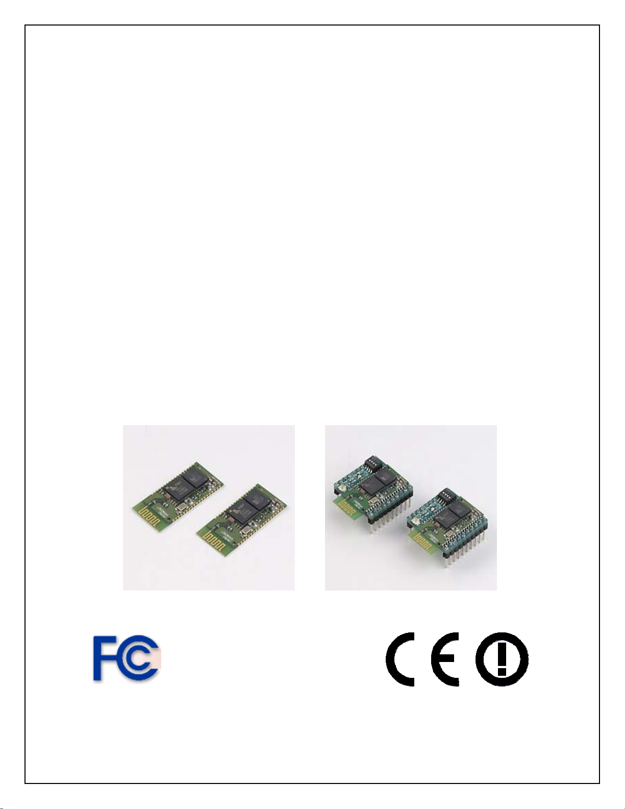
RoHS Serial TTL Bluetooth Modules
RB4000 RB4000HM
April 18, 2012
RoHS Compliant
1
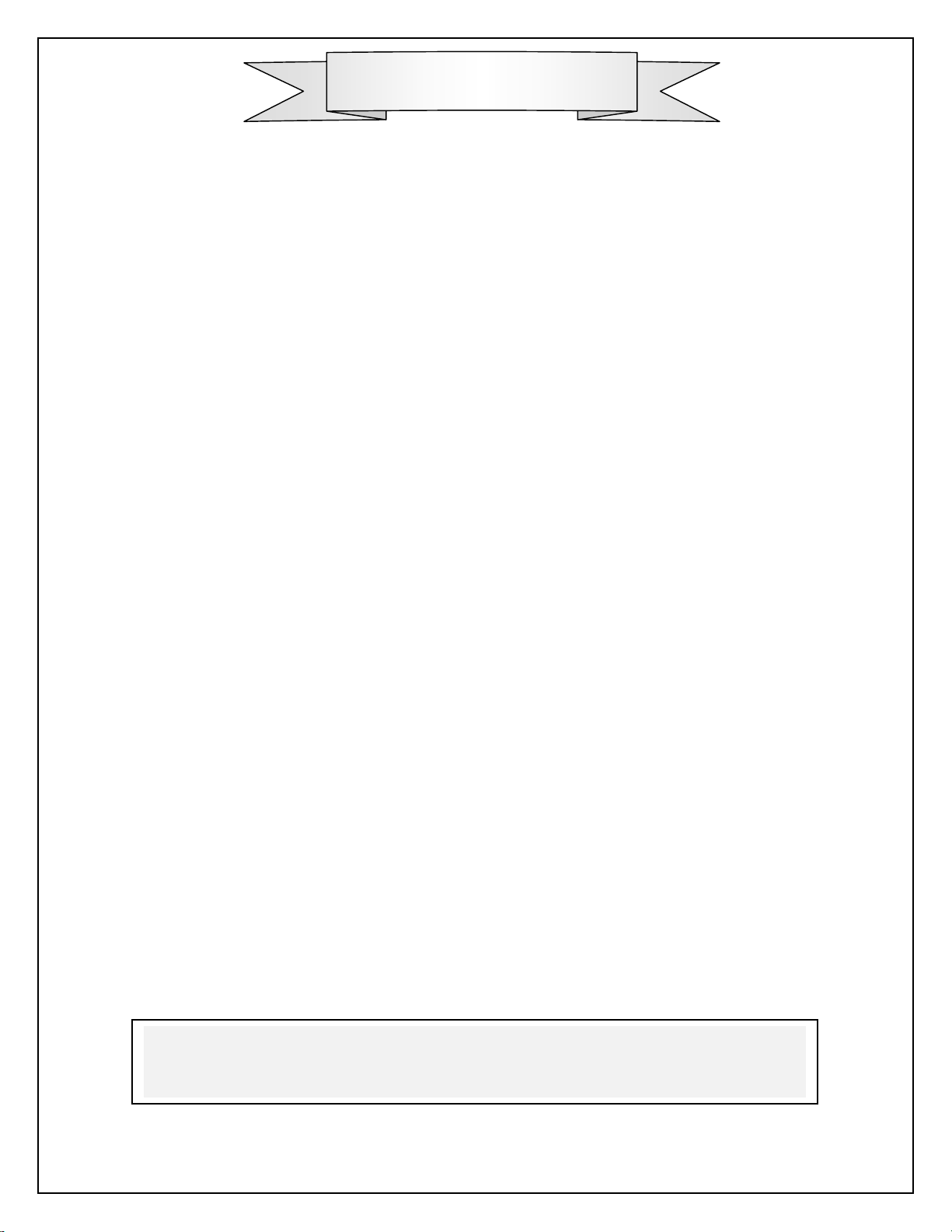
Table of Contents
Introduction 3
Features 4
Specifications 5
Model and Ordering Information 6
FCC& IC Label and Model Identification 7
Important Regulatory Compliance and User Information 8
CE Declaration of Conformity 10
Layout Design Suggestions 10
RB4000 Pad Size 11
RB4000 Mechanical Diagram & Pin Assignments 12
RB4000 Interface Signal Level Definitions 13
RB4000HM Mechanical Diagram & Pin Assignments 14
RB4000HM Switch settings 15
RB4000HM Interface Signal Level Definitions 15
RB4000MB Carrier Board RS232 DB 9 Pin Definitions 16
LED Operation 16
Connecting to Your System 17
Limited Warranty 18
Contacting Radicom Research 20
Information furnished by Radicom Research is believed to be accurate and reliable. However Radicom
Research assumes no responsibility for its use, or any infringement of patents or other rights of third
parties that may result from its use. Radicom Research reserves the right to change circuitry at any time
without notice. This document is subject to change without notice.
2

Introduction
Thank you for purchasing Radicom Research’s RB4000 Bluetooth Module. We are
committed to providing you quality service and technical support. The RB4000 and
RB4000HM Bluetooth modules are designed to meet OEM’s needs of embedding shortrange wireless data connectivity to their products. The RB4000 family offers a quick and
simple solution for wireless point-to-point Bluetooth communications.
The RB4000 series are Class 2 Bluetooth modules using BlueCore4-External Chipset
from CSR, the leader in Bluetooth chipsets. These embedded modules are Bluetooth
V.2.0 + EDR (Enhanced Data Rate) compliant that increase throughput, reduce battery
consumption and improve security. It provides faster pairing and allows superior
performance in the presence of interference from 802.11 WiFi wireless devices and other
2.4GHz radios.
The RB4000 series has 8Mbits flash memory on board for upgrading the modules
firmware. OEM specific parameters and settings can be loaded into these modules.
Radicom can modify the firmware to meet OEM requirements and create custom
Bluetooth functionality to meet your specific needs.
The RB4000 Series supports Serial Port Profile functionality for setting up virtual serial
ports on two devices (e.g. PCs) and connecting the two devices using the RB4000
Bluetooth modules to emulate a RS232 serial cable between the two devices.
There are 4 models available, RB4000, H4000CE, RB4000HM-a, and RB4000HM-c.
The RB4000 and H4000CE are surface mount PCB Bluetooth modules with on-board
antenna. The RB4000 and H4000CE are identical except for the name that was changed
for marketing reasons. The RB4000HM-a is serial through-hole Bluetooth module with
an on board antenna. The RB4000HM-c is serial through-hole Bluetooth module with an
U.FL connector for an external antenna to provide the flexibility for placing antennas in a
desired location. For evaluation purposes we offer kits for both the onboard and external
antenna versions of the modules. Each kit will include one each SPP-A Initiator and SPPB Acceptor Bluetooth module installed into carrier boards with a RS232 Serial connector.
Upon receipt of the Evaluation kits, the user can immediately connect the carrier boards
to any standard serial port to evaluate the Bluetooth modules.
3

Features
• Bluetooth 2.0+EDR support
• Small sizes: 0.57” x 1.26” x 0.08” (RB4000) or 1” x 1.26” x 0.2” (RB4000HM)
• Class 2 radio, 4dBm transmission power
• Serial Port Profile (SPP) support
• Secure simple pairing support
• Link Data Rate 2.1Mbps Max
• SPP/ UART data rates: 115.2Kbps
• GAP (Generic Access Protocol)
• SDP (Service Discovery Protocol)
• L2CAP (Logical link control and adaptation protocol)
• RFCOMM embedded stack profiles support
• 8Mbits flash memory on board
• Secure communications with 128-bit encryption
• Onboard antenna or with an U.FL connector for external antenna
• Supports 802.11 wireless co-existence
• Custom application specific Firmware is possible. Contact Radicom Research, Inc.
•
Available as either SPP-A Initiator and SPP-B Acceptor Bluetooth module
•
RTS/CTS Flow Control (Hardware Flow Control) Supported
Approvals
• FCC Part 15: FCC OET 65 Supplement C (SAR), 47 CFR FCC Part 15
Subpart C 15.247, 47 CFR FCC Part 15 Subpart B 2009 (Class B)
• IC RSS-102, IC ES-003 issue 4, IC RSS-210 issue 8:2010
• RoHS Compliant
• CE Marked: EN 61000-3-2:2006+A2:2009, EN 62311:2008, EN 300 328 V1.7.1,
EN 301 489-1, V1.8.1, EN 61000-3-3:2008, EN 301 489-17 V2.1.1)
• EN 60950-1:2006+A11:2009+A1:2010+A12:2011
4
Specifications
(
Dimensions
Device Type
Interface
Data Link Protocol
Frequency
Frequency Range
Max Transmit Power
Receive Sensitivity
Bluetooth Class
Link Data Transfer Rate
UART /SPP Data Transfer
Rate
Sustained Data Through-put
Flow Control
Range
RB4000: 0.57”x1.26”x0.08” ?????
RB4000HM: 1” x 1.26” x 0.2” ??????
Embedded Bluetooth OEM module
Serial
Bluetooth 2.0+EDR
ISM 2.4 GHz short-range radio frequency band
2,402 – 2,483.5 MHz
+4dBm
-89dBm
Class 2
2.1Mbps Max
115.2Kbps
720Kbps
RTS/CTS Hardware
Up to 20 meters (60 feet, basic rate, line of sight)
On Board Flash
Compliant Standards
Security
Supply Voltage: VDD
Current Consumption
Antenna
On-Board Antenna Gain
External Antenna Gain
Baseband Crystal OSC
RF Input Impedance
Receiver IF Frequency
Receiving Signal Range
Hopping
8Mbits
Bluetooth 1.1, 1.2, and 2.0
128-bit encryption
2.2V to 4.2V (RB4000) or 3.15V ~ 3.45V (RB4000HM)
SPP-A Code SPP-B Code
Before connection: 40mA 38mA
Connected (Sniff Mode): 7mA 15mA
Connected
On-board antenna or with an U.FL connector for external
antenna
1 dBi
2 dBi
16MHz
50 ohms
1.5MHz
-80 to –20dBm typical
1600hops/sec, 1MHz channel space
full TX/RX): 11mA 35mA
Operating Temperature
Environmental
-40ºC to +85ºC
RoHS compliant
5
Model and Ordering Information
Model Number Description
RB4000 or
H4000CE
RB4000HM (-a + -c)
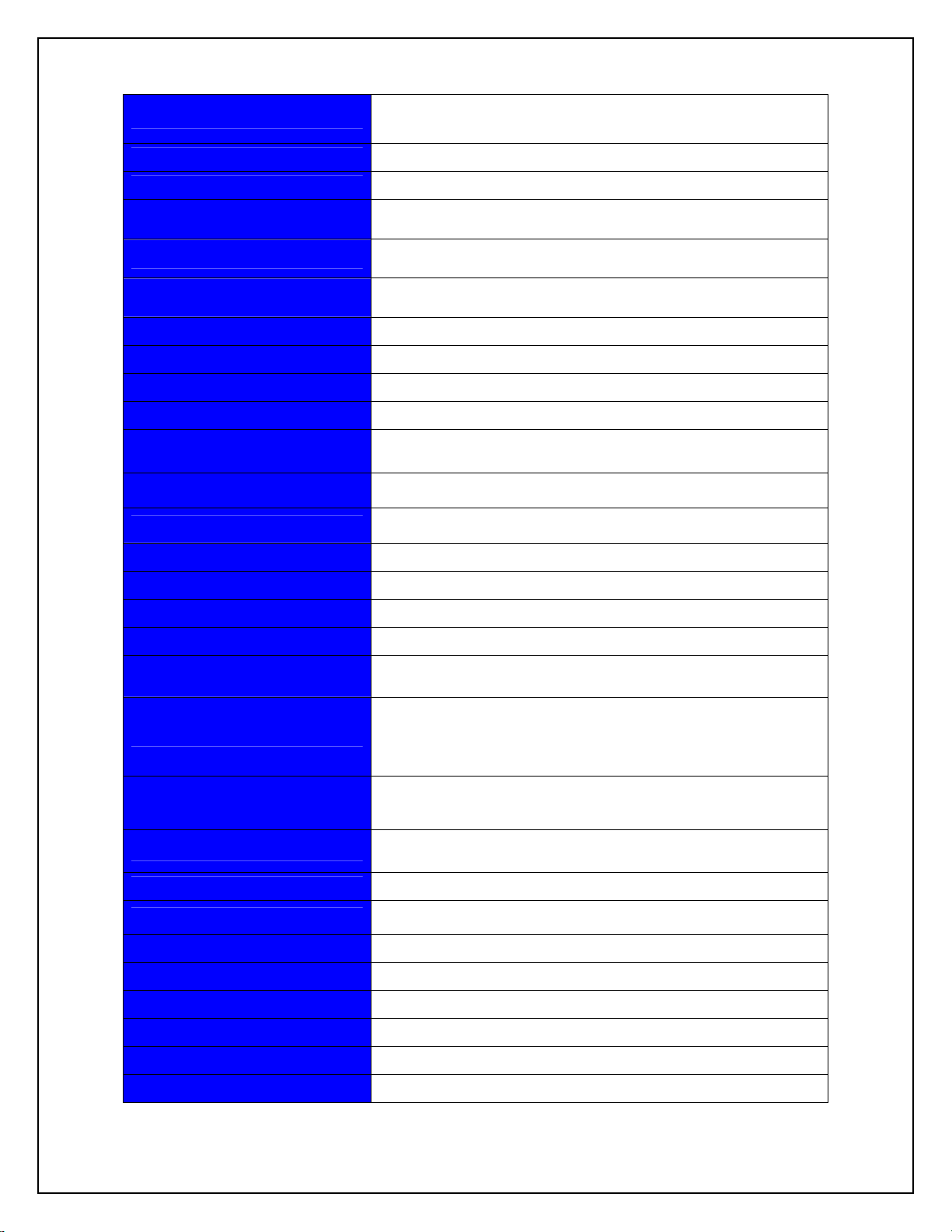
RB4000MB
0.57" x 1.26" x 0.08" surface mount, short range Bluetooth
module with on-board antenna
Model: RB4000
The RB4000 is the same as the H4000CE. The name is different
for marketing purposes only.
Available as either SPP-A Initiator and SPP-B Acceptor
Bluetooth module
1.0" x 1.26" x 0.2" dual-in-line, through-hole Bluetooth module
Model: RB4000HM-a - PCB antenna on-board.
Model: RB4000HM-c - With on-board U.FL antenna
connector for external antenna
RB4000MB Carrier board with Bluetooth Module installed,
USB Type B receptacle for power, DB9M connector and AC
power receptacle installed for optional AC power adapter
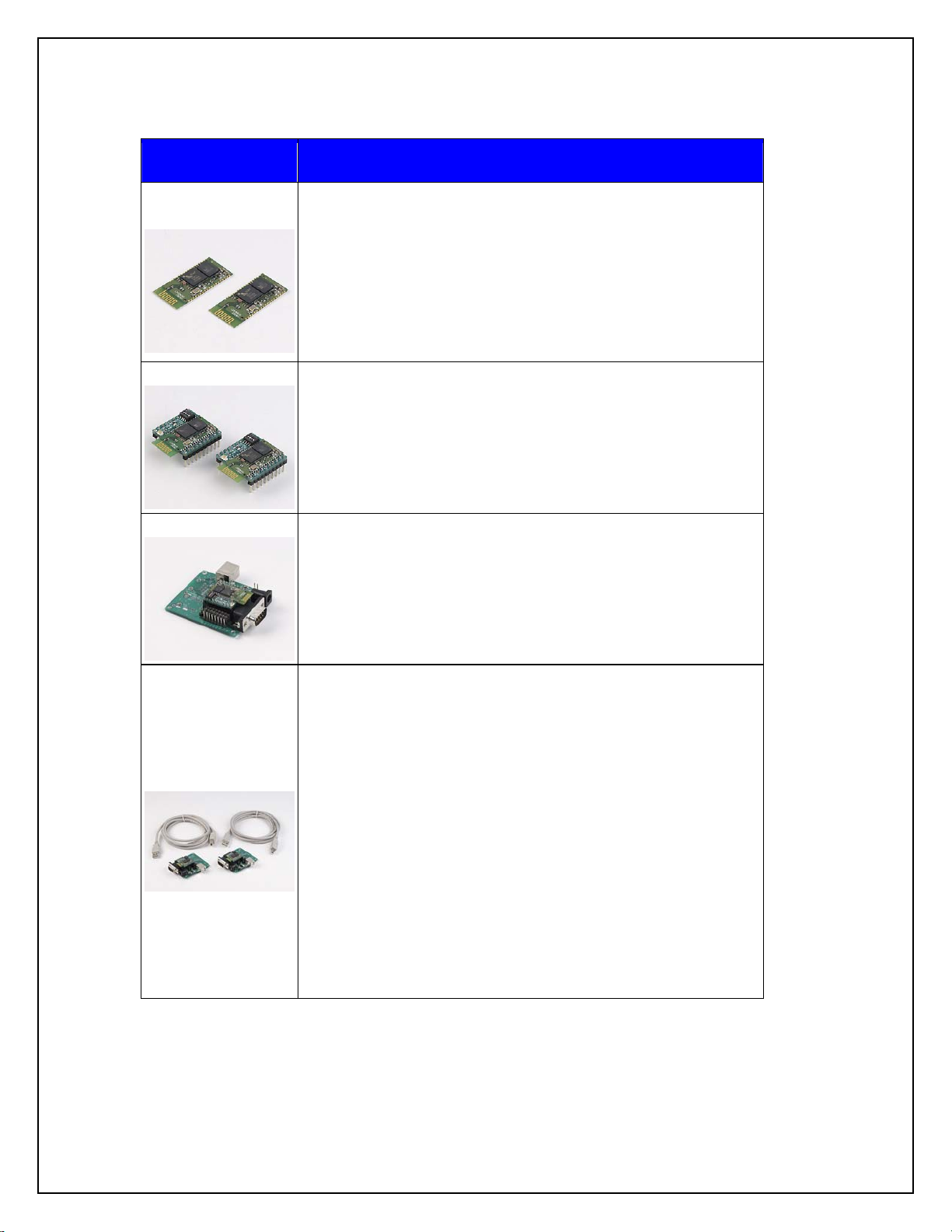
MDK4000
RB4000 Development Kit. Each kit consists of the following
components:
1. 2ea Carrier Boards with Bluetooth Modules (Pair of
modules configured as SPP-A for Initiator and SPP–B for
Acceptor each installed into RB4000MB Carrier Board)
2. 2ea. 6 feet USB Power cables (A to B)
3. 2ea. Null modem cables (DB9F to DB9F)
4. 2ea AC Power adapters (optional required if USB power
unavailable)
5. 2ea external antennas (optional for RB4000HM-c)
6. 2ea antenna cables (optional for RB4000HM-c)
6

ATN-2d-RP-SMA
AC6i-RP-SMA
Replacement antenna, 2.4GHz, 2dBi, RP-SMA, Omni-directional.
6" U.FL. to RP-SMA female connector antenna cable
FCC & IC Label and Model Identification
The RB4000 module family is FCC Part 15 and IC (Industry Canada) certified. The
RB4000 is also CE marked. The modules are labeled with the appropriate RB4000
module model number and FCC Part 15 ID, IC registration number and CE mark. The
label can be found on top of the metal shielding on the RB4000 Module.
Radicom Research Inc.
Model: RB4000
FCC ID: K7T-RB4000
IC: 2377A-RB4000
Note: Models RB4000HM-a and RB4000HM-c will have an additional Product ID label
containing the HM model numbers.
7

Important Regulatory Compliance and User Information
The final product with the modules installed needs to be tested for FCC Part 15, IC
(Industry Canada) CE, EMI/RFI compliance. Radicom certification documentation will
help streamline the final product approval process. Contact Radicom for more
information. To maintain compliance in the finished product, carefully follow guidelines
in this section. This device is intended only for OEM integrators under the following
condition:
The transmitter module may not be co-located with any other transmitter or antenna. As
long as this condition is met, further transmitter testing will not be required. However, the
OEM integrator is still responsible for testing their end product for any additional
compliance requirements required with the module installed (for example, digital device
emissions, PC peripheral requirements, etc). IMPORTANT NOTE: In the event that
this condition
the FCC ID
integrator will be responsible for re-evaluating the end product (including the transmitter)
and obtaining a separate FCC authorization.
Host (End Product) Labeling Requirements
cannot be met then the FCC authorization is no longer considered valid and
cannot be used on the final product. In these circumstances, the OEM
To maintain compliance, the end product hosting the module must be properly labeled to
identify that this module is installed. The final end product must have a label located in a
visible area with the following information:
Contains Transmitter
Module
Model: XXXXXXX
FCC ID: K7T-RB4000
IC: 2377A-RB4000
XXXXXXX is for the model of the RB400HM used in the end equipment. The
XXXXXXX will be RB4000, H4000CE. RB4000HM-a or RB4000HM-c. The label shall
be securely affixed to a permanently attached part of the device, in a location where it is
visible or easily accessible to the user, and shall not be readily detachable. The label shall
be sufficiently durable to remain fully legible and intact on the device in all normal
conditions of use throughout the device’s expected lifetime. These requirements may be
met either by a separate label or nameplate permanently attached to the device or by
permanently imprinting or impressing the label directly onto the device. The label text
shall be legible without the aid of magnification, but is not required to be larger than 8point font size.
8

End User Information
This equipment complies with FCC radiation exposure limits set forth for an uncontrolled
environment. End users must follow the specific operating instructions for satisfying RF
Exposure compliance. The end user should NOT be provided any instructions on how to
remove or install the device. The users manual for end users must include the following
information in a prominent location
FCC RF Radiation Exposure Statement
IMPORTANT NOTE: To comply with the FCC RF exposure compliance
requirements, this device must not be co-located or operating in conjunction with any
antenna or transmitter. This device contains a low power transmitter. When this device is
operational, use only with the supplied, or recommended antenna. Unauthorized antenna,
modification, or attachments could damage the transmitter and may violate FCC
regulations. Changes or modifications not expressly approved by the manufacturer or
party responsible for compliance could void the user’s authority to operate the
equipment.
FCC Interference Statement
This device complies with Part 15 of the FCC Rules. Operation is subject to the following conditions:
(1) This device may not cause harmful interference
(2) This device must accept any interference received, including interference
that may cause undesired operation.
This equipment has been tested and found to comply with the limits for a Class B
digital device, pursuant to Part 15 of the FCC Rules. These limits are designed to provide
reasonable protection against harmful interference in a residential installation.
This equipment generates and radiates radio frequency energy and, if not installed
and used in accordance with the instructions, may cause harmful interference to radio
communications. There is no guarantee that interference will not occur in a particular
installation. If this equipment does cause harmful interference to radio or television
reception, which can be determined by turning the equipment off and on, the user is
encouraged to try to correct the interference by one of the following measures:
● Reorient or relocate the receiving antenna.
● Increase the separation between the equipment and receiver.
● Connect the equipment into an outlet on a circuit different from that to which the
receiver is connected.
● Consult the dealer or an experienced radio/TV technician for assistance.
IC (Industry Canada) Statement:
“This device complies with Industry Canada license-exempt RSS standard(s). Operation
is subject to the following two conditions: (1) this device may not cause interference, and
(2) this device must accept any interference, including interference that may cause
undesired operation of the device”
Le present appareil est conforme aux CNR d’Industrie Canada applicables aux appareils
radio exempts de license. L’exploitation est autorisee aux deux conditions suivantes: (1)
l’appareil ne doit pas produire de brouillage, et (2) l’utilisateur de l’appareil doit acceptor
tout brouillage radioelectrique subi, meme si le brouillage est susceptible d’en
compromettre le fonctionnement.
9

CE Declaration of Conformity
For the following equipment:
Radicom Research Inc. Bluetooth Module
Model(s): RB4000, H4000CE, RB4000HM-a, and RB4000HM-c
are herewith confirmed to comply with the requirements set out in the Council
(European parliament) Directive on the Approximation of the Laws of the
Member States relating to Electromagnetic Compatibility of Radio and Telecom
device (1999/5/CE). For the evaluation regarding this Directive, the following
standards were applied:
EN 61000-3-2:2006+A2:2009, EN 300 328 V1.7.1, EN 62311: 2008,
EN 301 489-1, V1.8.1, EN 61000-3-3:2008, EN 301 489-17 V2.1.1
EN 60950-1:2006+A11:2009+A1: 2010+A12:2011
________________________
This equipment is marked with the and can be used throughout the
European community.
France – 2.4GHz for Metropolitan France:
In all Metropolitan departments, wireless LAN frequencies can be used under the
following conditions, either for public or private use:
• Indoor use: maximum power (EIRP*) of 100 mW for the entire 2400-2483.5
MHz frequency band
• Outdoor use: maximum power (EIRP*) of 100 mW for the 2400-2454 MHz band
and with maximum power (EIRP*) of 10 mW for the 2454-2483 MHz band
Europe – R&TTE Compliance Statement:
Hereby, Radicom Research Inc. declares that this equipment complies with the essential
requirements and other relevant provisions of DIRECTIVE 1999/5/CE OF THE
EUROPEAN PARLIAMENT AND THE COUNCIL of March 9, 1999 on radio
equipment and telecommunication terminal Equipment and the mutual recognition of
their conformity (R&TTE).
Layout Design Suggestions
• General Layout Rules- All Printed Circuit Boards must comply with UL94V0
standard for flammability. Always use RoHS compliant Parts and materials.
• Suggestions for Layout:
1. Do not place Power circuit, X’tal, Inductor, etc near RF area.
10

2. The bigger Antenna clearance area, the better. The Antenna itself needs to stay away
from any circuit or component at least 2mm. Antenna clearance area means Top and
Bottom both required to be cleared.
3. Do not use metal materials on design where near Antenna area. For example, battery
snaps, USB connector, iron case, etc.
4. For RB4000HM-c model (external antenna type), when RF trace meets a turning
point, try to make the RF trace as smooth as you can’t use right angle trace.
These guidelines are for design reference; real performance still depends on actual
design.
RB4000 Pad Size (mm)
11

RB4000 Mechanical Diagram (inches) & Pin Assignments
12

RB4000 Interface Signal Level Definitions
Note: I/O is DTE not DCE. RTS and CTS functionality is for Hardware Flow
Control.
Pin # Pin Name Type Description I/O Voltage Range
1 GND - Ground 2 Reserved -
3 GND - Ground -
4 Reserved -
5 Reserved -
6 RESET I Reset if low for more than
5ms
7 SPI_MISO O Synchronous serial interface
data output
8 SPI_CSB I Chip select for Synchronous
Serial Interface
active low
9 SPI_CLK I Synchronous serial interface
clock
10 SPI_MOSI I Synchronous serial interface
data input
11 UART_CTS I UART clear to send active
low
12 UART_TX O UART data output Vol: 0V ~ 0.2V
13 UART_RTS O UART request to send
active low
14 UART_RX I UART data input Vil: 0V ~ 0.3 x VDD
15 Reserved O
16 VDD PWR Supply voltage 2.2V ~ 4.2V
17 GND - Ground
18 Reserved -
19 Reserved -
20 Reserved -
21 Reserved -
22 Reserved -
23 Reserved -
24 Reserved -
25 Reserved -
26 Reserved -
Vil: 0V ~ 0.3 x VDD
Vih: 0.7 x VDD
Vol: 0V ~ 0.2V
Voh: VDD – 0.2V ~ VDD
Vil: 0V ~ 0.3 x VDD
Vih: 0.7 x VDD
Vil: 0V ~ 0.3 x VDD
Vih: 0.7 x VDD
Vil: 0V ~ 0.3 x VDD
Vih: 0.7 x VDD
Vil: 0V ~ 0.3 x VDD
Vih: 0.7 x VDD
Voh: VDD – 0.2V ~ VDD
Vol: 0V ~ 0.2V
Voh: VDD – 0.2V ~ VDD
Vih: 0.7 x VDD
27 Reserved -
28 Reserved -
29 Reserved -
30 Reserved -
31 Reserved -
32 Reserved -
33 Reserved -
34 Reserved -
35 LINK LED O Link LED Output Vol: 0V ~ 0.2V
Voh: VDD – 0.2V ~ VDD
36 GND - Ground -
13

RB4000HM Mechanical Diagram & Pin Assignments
Notes:
1. Pin spacing is 0.100 inch from center to center.
2. Suggested mating female connector:
Samtec P/N. #SSW-110-21-G-S (RoHS Thru-Hole)
Samtec P/N. #SSW-110-22-G-S-VS (RoHS SMT)
3. Square pins - 0.025" x 0.025"
14

RB4000HM Switch settings:
This Switch is reserved for future use. Do not change. They all should be set to the OFF
position.
DTE Speed 1 2 3
115200
(Default)
OFF OFF OFF
RB4000HM Interface Signal Level Definitions
Pin # Pin Name Type Description I/O Voltage Range
1 KEY -
2 Not Used - No connection
3 LINK LED O Link LED output Vol: 0V ~ 0.2V
Voh: 2.8V ~ 3.3V
4 3.3 VDD PWR Supply voltage 3.15V ~ 3.45V
5 _RESET I Reset if low for more
than 5ms
6 GND - Ground
7 Reserved -
8 Reserved -
Vil: 0V ~ 0.99V
Vih: 2.31V ~ 3.3V
9 Reserved -
10 Reserved -
11 Reserved -
12 Reserved -
13 Reserved -
14 _CTS I UART clear to send
active low
15 Reserved -
16 Reserved -
17 _RTS O UART request to send
active low
18 _TX O UART data output Vol: 0V ~ 0.2V
19 _RX I UART data input Vil: 0V ~ 0.99V
20 Reserved -
Note: I/O is DTE not DCE. RTS and CTS functionality is for Hardware Flow
Control.
Vil: 0V ~ 0.99V
Vih: 2.31V ~ 3.3V
Vol: 0V ~ 0.2V
Voh: 2.8V ~ 3.3V
Voh: 2.8V ~ 3.3V
Vih: 2.31V ~ 3.3V
15

RB4000MB Carrier Board RS232 DB 9 Pin Definitions
The pin definitions of DB9 used on the RB4000MB RS232 Serial Connector are as
follows:
1. DCD: Input, Carrier Detect
2. RXD: Input, Received Data
3. TXD: Output, Transmit data
4. DTR: Output, Data Terminal ready
5. GND: Ground
6 DSR: Input, Data Set Ready
7. RTS: Output, Request to Send
8. CTS: Input, Clear to Send
9. RI: Input, Ring Indicator
LED Operation
The modules have an On Board LED to indicate the Bluetooth Connection Status. The
LED will start blinking after power is applied (once every two seconds). The module is
ready to establish a connection. Once a connection is established, the Acceptor Module
LED will flash twice every 2 seconds and the Initiator Module LED will be ON
continuously.
Mode RB4000MB-SPP-A Initiator RB4000MB SPP-B Acceptor
Searching LED status 700ms on,
700ms off
Connect Always ON Flashes twice every 2 seconds
The modules also have an I/O Pin to add the LED to your design. The RB4000-HM LED
output is Pin 3 and the RB4000 LED output is Pin 35.
LED flashing once every 2
seconds
16

Connecting to Your System
NOTE: Do Not Plug in the USB cable and AC power adapter at the
same time. Only use one or the other. Plugging in both the USB cable and AC power
adapter may damage the USB port on your PC or USB device.
Below is a simple example to show how the Radicom Bluetooth modules work. This
example demonstrates how the Bluetooth Modules can connect to each other.
1. RB4000MB-SPP-A Initiator setup: Open HyperTerminal and select an available
Serial Comport. Set the DTE speed to 115200bps, 8 Data bit, No Parity bit, One
Stop bit and No Flow control.
2. Connect one end of the RS232 Null modem cable (DB9 Female to DB9 Female)
to the Serial Comport and the other end of the cable to the RB4000MB-SPP-A
3. Apply power using either a USB cable or Optionally provided AC power adapter
to RB4000MB-SPP-A. The modules Firmware message should show up on the
HyperTerminal screen and the LED on the RB4000MB-SPP-A should be ON.
4. RB4000MB-SPP-B setup: Open HyperTerminal and select an available Serial
Comport. Set the DTE speed to 115200bps, 8 Data bit, No Parity bit, One Stop bit
and No Flow control.
5. Connect one end of the RS232 Null modem cable (DB9 Female to DB9 Female)
to the Serial Comport and the other end of the cable to the RB4000MB-SPP-B.
6. Apply power using either a USB cable or Optionally provided AC power adapter
to RB4000MB-SPP-A. The modules Firmware message should show up on the
HyperTerminal screen and the LED on the RB4000MB-SPP-B then start blinking.
7. When both Modules are powered-up, they should automatically connect to each
other as long as the modules are within acceptable distance, for example, 10m in
home or office).
8. The on board LEDs will show the modules Connect Status.
Note(s): They further apart the modules are, the longer it may take to connect and the
slower the data transfers will be. If the modules do not connect make sure that the
firmware displayed reflects that one module contains Initiator firmware and the other
module contains Acceptor firmware. For example, the Initiator should display SPP-B
XXX and the Acceptor should display SPP-A XXX where XXX is the firmware version.
Note: When Connected and no data activity, the modules will enter lower power Sniff
Mode after 5 to 7 seconds of inactivity. Any transmitted or received data will cause the
module to exit Sniff Mode and resume normal operation.
17

Limited Warranty
Warranty Coverage and Duration
Radicom Research, Inc. (“RRI”) warrants to the original purchaser its RRI-manufactured
products (“Product”) against defects in material and workmanship under normal use and
service for a period of one year from the date of delivery.
During the applicable warranty period, at no charge, RRI will, at its option, either repair,
replace or refund the purchase price of this Product, provided it is returned in accordance
with the terms of this warranty to RRI. Repair, at the option of RRI, may include the
replacement of parts, boards or other components with functionally equivalent
reconditioned or new parts, boards or other components. Replaced parts, boards or other
components are warranted for the balance of the original applicable warranty period. All
replaced items shall become the property of RRI.
RRI MAKES NO GUARANTEE OR WARRANTY THAT THE PRODUCT WILL
PREVENT OCCURRENCES, OR THE CONSEQUENCES THEREOF, WHICH THE
PRODUCT IS DESIGNED TO DETECT.
This expressed limited warranty is extended by RRI to the original end-user purchaser
only, and is not assignable or transferable to any other party. This is the complete
warranty for the Product manufactured by RRI, and RRI assumes no obligation or
liability for additions or modifications to this warranty. In no case does RRI warrant the
installation, maintenance or service of the Product.
RRI is not responsible in any way for any ancillary equipment not furnished by RRI that
is attached to or used in connection with the Product, or for operation of the Product with
any ancillary equipment, and all such equipment is expressly excluded from this
warranty. Because of wide variations in topographical and atmospheric conditions,
which may require availability of repeater stations or of particular radio frequencies, RRI
assumes no liability for range, coverage or suitability of the Product for any particular
application. Buyer acknowledges that RRI does not know a particular purpose for which
buyer wants the product, and that buyer is not relying on RRI’s skill and judgment to
select or furnish suitable goods.
What this Warranty does NOT Cover:
(a) Defects or damage resulting from use of the Product in other than its normal and
customary manner.
(b) Defects or damage from misuse, accident or neglect.
(c) Defects of damage from improper testing, operation, maintenance, installation,
alteration, modification or adjustment.
(d) Disassembly or repair of the Product in such a manner as to adversely affect
performance or prevent adequate inspection and testing to verify any warranty claim.
(e) Any Product that has had its serial number or date code removed or made illegible.
18

How to Receive Warranty Service:
To obtain warranty service, contact RRI by phone (408)-383 9006 for RMA Department
or email to rma@radi.com for an RMA (Return Merchandise Authorization) number.
Deliver or send the Product, transportation and insurance prepaid to RRI, with the RMA
number clearly marked on the outside of the package.
General Provision
This warranty sets forth the full extent of RRI’s responsibilities regarding the Product.
Repair, replacement or refund of the purchase price, at RRI’s option, is the exclusive
remedy.
THIS WARRANTY IS GIVEN IN LIEU OF ALL OTHER EXPRESSED
WARRANTIES. ANY APPLICABLE IMPLIED WARRANTIES, INCLUDING
WITHOUT LIMITATION, THE IMPLIED WARRANTY OF MERCHANTABILITY,
ARE LIMITED TO THE DURATION OF THIS LIMITED WARRANTY. TO THE
FULLEST EXTENT PERMITTED BY LAW, RRI DISCLAIMS ANY LIABILITY
FOR DAMAGES IN EXCESS OF THE PURCHASE PRICE OF THE PRODUCT, FOR
ANY LOSS OF USE, LOSS OF TIME, INCONVENIENCE, COMMERCIAL LOSS,
LOST PROFITS OR SAVING OR OTHER INCIDENTAL, SPECIAL OR
CONSEQUENTIAL DAMAGES ARISING OUT OF THE USE OR INABILITY TO
USE OR FAILURE OF SUCH PRODUCT.
19

Contacting Radicom Research
If more information or technical support is needed, please contact us:
2148 Bering Drive
San Jose, CA. 95131
Telephone: (408) 383 9006
Fax: (408) 383 9007
or
e-mail:
sales@radi.com
http://www.radi.com/
20
 Loading...