

Radiant RSF 20 E, RSF 30 E, RSF 24 E Installation And Maintenance Manual
CE
0694 TA05A27.A0504
Technical Specification RADIANT BRUCIATORI S.p.A. Montelabbate (PU) ITALY ENGLISH
INSTALLATION,
AND MAINTENANCE MANUAL
FOR GAS FIRED, WALL-HUNG BOILERS
models RSF 20 E • RSF 24 E • RSF 30 E
TYPE C ROOM SEALED
SEDBUK BAND D


INDEX
PRODUCT CONFORMITY page 1
INSTALLATION INSTRUCTIONS AND WARNINGS page 2
TECHNICAL DATA page 4
OVERALL DIMENSIONS - EXHAUST FLUE SYSTEM page 5
GENERAL INSTALLATION REQUIREMENTS page 8
BOILER INSTALLATION page 10
ELECTRICAL CONNECTIONS page 12
BOILER CONTROL PANEL page 13
STARTING UP THE BOILER FOR THE FIRST TIME page 13
MULTIGAS OPERATION page 15
GAS TABLE - REGULATING THE GAS PRESSURE page 16
GAS PRESSURE DIAGRAMS page 17
MAIN COMPONENTS page 18
WIRING DIAGRAMS page 19
MAINTENANCE page 21
UNPACKING page 21
FAULT FINDING CHART page 22
SHORT LIST OF COMPONENTS page 23

Installation Manual
HEAT TECNOLOGY SINCE 1959
Thank you for choosing RADIANT
Declaration for purposes of Art. 7 of Law 46 of 5 April 1990.
RADIANT BRUCIATORI S.p.A. hereby declares that all of its products are constructed to industry standards as required by the Article in
question and by Article 5 of the law in effect (D.P.R. no. 447/97).
All RADIANT boilers are constructed according to:
• UNI-CIG 7271 (april 1988)
• UNI-CIG 9893 (december 1991 )
• EUROPEAN STANDARD UNI EN 297 Gas-fired central heating boilers - Type B
11
e B
11BS
boilers fitted atmospheric burners of nominal
heat input not exceeding 70 kW;
• EN 483 Gas-fired central heating boilers – Type C boilers of nominal heat input non exceeding 70 kW;
• EUROPEAN STANDARD UNI EN 677 Gas-fired central heating boilers – Specific requirements for condensino boilers with a nominal
heat input not exceeding 70 kW;
• GAS DIRECTIVE 90/396 EEC for CE marking - Appliances burning gaseous fuels
• GAS DIRECTIVE 73/23/EEC - Low voltage
• GAS DIRECTIVE 89/336/EEC - Electromagnetic compatibility
• GAS DIRECTIVE 92/42/ECC requirements for new hot-water boilers fired with liquid or gaseous fuels
All RADIANT boilers are constructed according to UNI - CIG (EC) norms. The materials used, such as copper, brass, and stainless steel
form a compact, homogeneous, highly functional unit that is easy to install and simple to operate. The wall-mounted boiler is equipped with
all of the approved accessories required to make it a true, independent heating plant for home heating and for the production of hot water for
domestic needs. All boilers are fully inspected, and come with a certificate of quality signed by the inspector and with a warranty certificate.
This booklet must be read carefully and stored in a safe place, accompanying the boiler at all times.
RADIANT BRUCIATORI S.p.A. declines any and all responsibility for misinterpretations of this booklet deriving from any
translations of same.
RADIANT BRUCIATORI S.p.A. will not be responsible for non-observance of the instructions contained in this booklet or for the
consequences of any action not specifically described herein.
DOMESTIC HOT WATER WITH STORAGE CYLINDER – TA05A027.A0504
1

Installation Manual
INSTALLATION INSTRUCTIONS - WARNINGS
THIS INSTALLATION, USE, AND MAINTENANCE MANUAL IS AN ESSENTIAL AND INTEGRAL PART OF THE PRODUCT, AND MUST
ALWAYS BE KEPT NEAR THE DEVICE.
THE WARNINGS CONTAINED IN THIS SECTION ARE ADDRESSED BOTH TO THE USER AND TO INSTALLATION AND
MAINTENANCE PERSONNEL.
THE USER WILL FIND INFORMATION ON OPERATION AND LIMITS OF USE IN THE ACCOMPANYING MANUAL, WHICH SHOULD BE
READ VERY CAREFULLY.
STORE THE MANUAL CAREFULLY FOR FUTURE REFERENCE.
1) GENERAL WARNINGS
INSTALLATION MUST BE PERFORMED IN OBSERVANCE OF CURRENT NORMS, ACCORDING TO THE CONSTRUCTOR’S
INSTRUCTIONS, AND BY PROFESSIONALLY QUALIFIED PERSONNEL.
THE INSTALLATION INSTRUCTIONS MANUAL MUST BE ALWAYS ACCOMPANY THE BOILER.
PROFESSIONALLY QUALIFIED PERSONNEL ARE THOSE HAVING TECHNICAL COMPETENCE IN THE SECTOR OF APPLICATION
OF THE DEVICE (CIVIL OR INDUSTRIAL), AND, IN PARTICULAR, THE CONSTRUCTOR’S AUTHORISED SERVICE CENTRES.
INCORRECT INSTALLATION MAY CAUSE DAMAGE TO PERSONS, ANIMALS, OR PROPERTY, FOR WHICH THE CONSTRUCTOR
ASSUMES NO LIABILITY.
• After completely removing the packing, make sure that the contents are in perfect condition.
• In case of doubt, do not use the equipment. Consult the supplier.
• Packing materials (cardboard carton, wooden crate, nails, clips, plastic bags, polystyrene, etc.) are potentially dangerous and must be
kept away from children.
• Before performing any cleaning or maintenance operation, turn off the unit by means of the mains switch and/or by means of the
appropriate cut-off devices.
• Do not block the air intake or heat dissipation grates.
• In the event of breakdown and/or poor functioning of the device, turn it off and do not attempt to repair it or take any direct action. Refer
to professionally qualified personnel only.
• Any repairs must be performed exclusively by a service centre authorised by the constructor, and with original spare parts only.
• Non-observance of the above instruction may compromise the safety of the device. To guarantee efficient and correct operation, the
device should undergo period maintenance by professionally qualified personnel according to the constructor’s instructions.
• Whenever the device is to be put out of service, secure all potentially hazardous parts to prevent accidents or damage.
• If the device is sold or transferred to another owner, or if you move and leave the boiler, make sure that this booklet stays with the boiler
so that it may be consulted by the new owner and/or by the installer.
• Use only original spare parts for all devices with optionals or kits (including electrical ones).
WARNING: this device must be used for its intended purpose, i.e., heating and production of domestic hot water. Any other use is improper
and therefore dangerous. The constructor will have no contractual or extracontractual liability for damage caused by incorrect installation
and/or use or by non-observance of instructions supplied by the constructor.
This device must be used exclusively with a sealed central heating system equipped with an expansion vessel.
2) WARNINGS REGARDING INSTALLATION
Warranty expires 12 months from date of installation and in all cases no later than 18 months from date of construction. First start-up
must be performed by authorised personnel only. For any operation on the hydraulic, gas, or electrical circuit regarding the heating unit,
refer to authorised technicians only and use original spare parts only. Wall-mounted boilers are not to be installed in damp rooms, and
must be protected against sprays or jets of water or other liquids to prevent malfunctions of the electrical and heating devices. They must not
be exposed to direct steam from cookers, and nothing must be placed on top of them. This heating unit has been constructed to heat the
home and to produce hot water. The constructor declines all responsibility for incorrect installation and/or use of the device. Do not
leave the device on when it is not being used: close the gas cock and turn off the mains switch. If you smell gas in the room in which the
device is installed, do not operate any electrical switches, telephones, or any other device that might cause a spark. Immediately open doors
and windows to create an air current to clear the room. Close the main gas cock (at the meter) or the cylinder cock, and request immediate
technical service.
Do not tamper with the device.
DOMESTIC HOT WATER WITH STORAGE CYLINDER – TA05A027.A0504
2

Installation Manual
SYSTEMS WITH THERMOSTATS
A by-pass must be installed in heating systems with radiators thermostats.
As required by current norms, these devices must be installed by qualified personnel only, who must respect norms UNI-CIG 7129 and
7131 and revisions, fire department regulations, and requirements of the local gas company. Before installing the boiler, make sure that the
water and heating systems are compatible with its output. The room must be properly ventilated by means of an air intake (see UNI 7129/92
and UNI 7129/95 FA).
The air intake must be at floor level open flue only, at a point where it cannot be obstructed, and protected by a grate that does not reduce
the useful section of flow.
The use of air flows from adjacent rooms is permitted as long as such rooms are in depression with respect to the outside and as long as
there are no wood-burning fireplaces or fans installed there. If the boiler is to be installed externally (for example, on balconies or
terraces), make sure that it is protected against atmospheric agents to prevent damage to components and voiding of the warranty. In such
cases we recommend building a heat compartment to protect the boiler against inclement weather.
Check the technical data on the packing and on the plate located inside the front casing. Check that the burner is suitable for use with
the type of gas available.
Make sure that all pipes and connections are perfectly sealed and that there are no gas leaks.
All pipework should be chemically flushed to remove any residues that might negative effect the operation of the boiler.
3) GENERAL WARNINGS BASED ON TYPE OF POWER SUPPLY
POWER SUPPLY
Electrical safety is achieved only when the device is correctly and efficiently earthed as per current safety norms (IEC 64-8 Electrical Part).
• This fundamental safety requirement must be checked. In case of doubt, request a check of the electrical system by professionally
qualified personnel. The constructor will not be liable for any damage caused by lack of or improper earthing of the system.
• Have professionally qualified personnel check that the electrical system is adequate for the maximum absorbed power of the device
(indicated on the plate). In particular, make sure that the section of the system wires is suitable for the maximum absorbed power of the
device.
• Do not use adapters, multiple sockets, and/or extension cords to power the device from the electrical mains.
• Provide a unipolar switch as required by current safety regulations to connect the device to the mains.
• The use of any electrical device requires the observance of some fundamental rules, such as:
• do not touch the device with wet or damp parts of the body and/or with bare feet
• do not pull on electrical cables
• do not expose the device to atmospheric agents (rain, sun, etc.) unless specifically provided for
• do not allow the device to be used by children or anyone unfamiliar with its operation
• The power cable must not be replaced by the user.
• If the cable becomes damaged, turn off the device and have the cable replaced by professionally qualified personnel only.
• If you decide not to use the device for an extended length of time, turn off the mains switch that feeds all components of the
system using electrical energy (pumps, burner, etc.).
DOMESTIC HOT WATER WITH STORAGE CYLINDER – TA05A027.A0504
3
Installation Manual
TECHNICAL DATA
Type C unit
Type C devices are devices in which the combustion circuit (air intake,
combustion chamber, exchanger, combustion exhaust) is sealed off
from the place where they are installed.
Coaxial vertical
Coaxial horizontal
C32
C12
C52 Double
MODELS RSF 20 E RSF 24 E RSF 30 E
Maximum rated input kcal/h 22016 25628 29670
kW 25.60 29.80 34.50
Btu/hr 87398 101737 117783
Minimum rated input kcal/h 10320 15050 16340
kW 12 17.5 19
Btu/hr 40968 59745 64866
Maximum rated output kcal/h 20387 23475 27445
kW 23.71 27.30 31.91
Btu/hr 80931 93191 108949
Minimum rated output kcal/h 9030 13191 14559
kW 10.50 15.34 16.93
Btu/hr 35847 52366 57796
Heating temperature adjustment °C 30-80 30-80 30-80
Max. working pressure (heating) bar 3 3 3
Min. working pressure (heating) bar 0.3 0.3 0.3
Expansion vessel capacity (initial pressure 1 bar) litres 10 10 10
Continuous hot water drawing with Dt 30° litres/min 11.33 13.04 15.25
Max. working pressure (water) bar 6 6 6
Min. working pressure (water) bar 0.3 0.3 0.3
Width mm. 410 450 450
Height mm. 800 800 800
Depth mm. 270 320 320
Weight kg. 42 47 50
Coaxial exhaust flue diameter kit A (max. flue lenght) Ø (m) 100/60 (3) 100/60 (3) Coaxial exhaust flue diameter kit G (max. flue lenght) Ø (m) - - 125/80 (3)
Double exhaust flue diameter kit B (max. flue lenght) Ø (m) 80/80 (30) 80/80 (30) 80/80 (30)
Double exhaust flue diameter kit C (max. flue lenght) Ø (m) 118/80 (3) 118/80 (3) 118/80 (3)
Flow/return connections Ø 3/4” - 3/4” 3/4” - 3/4” 3/4” - 3/4”
Cold water connections Ø 1/2” 1/2” 1/2”
Hot water connections Ø 1/2” 1/2” 1/2”
Gas connections Ø 1/2” 1/2” 1/2”
Electrical connection 50 Hz V 230 230 230
Power supply W 170 170 170
Electrical protection IP X4D X4D X4D
Nox class II I II
Burner jets NP 11 G20 Ø 1.30 - Burner jets NP 11 G30/31 Ø 0.78 - Burner jets NP 13 G20 Ø - 1.25 Burner jets NP 13 G30/31 Ø - 0.77 Burner jets NP 17 G20 Ø - - 1.20
Burner jets NP 17 G30/31 Ø - - 0.75
DOMESTIC HOT WATER WITH STORAGE CYLINDER – TA05A027.A0504
4
Installation Manual
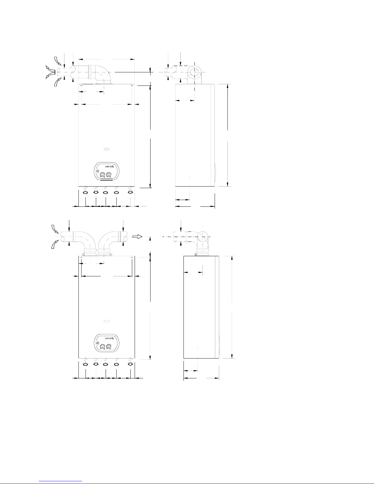
OVERALL DIMENSIONS - EXHAUST FLUE SYSTEM – mod. RSF 20 E
TYPE C WALL-MOUNTED BOILERS
31102807750 70
AF
G
R
C
95770166
ON 40
0.5
706050 80
807060
0.5
50ON 40
800
60
100
140
410
185
20
370
20
60
100
270
800
270
105
80
80
20
370
20
185
80
770
31102807750 70
CRGFA
140
105
SEALED COMBUSTION CIRCUIT:
Kit A
Horizontal coaxial exhaust flue
system with 360° rotation.
It allows the flue exhaust and the
air intake directly to an external
wall.
To insert a bend, reduce total flue
length by 0.8 m.
KEY
R RETURN ¾”
G GAS ½”
C HOT WATER ½”
F COLD WATER ½”
A HEATING FLOW ¾”
Kit B
Double exhaust/emission twin
flue system with 360° rotation.
It allows the flue exhaust into a flue
duct and the air intake directly from
an external wall.
To insert a bend, reduce total flue
length by 1.5 m.
NOTE: USE ORIGINAL RADIANT APPROVED FLUE KIT SYSTEMS, FLUE ACCESSORIES AND FLUE DIAPHRAGMS ONLY.
APPROVED RADIANT FLUE DIAPHRAGMS AND ADJUSTMENT TABLES ARE SUPPLIED WITH RADIANT ORIGINAL FLUE.
DOMESTIC HOT WATER WITH STORAGE CYLINDER – TA05A027.A0504
5
Installation Manual
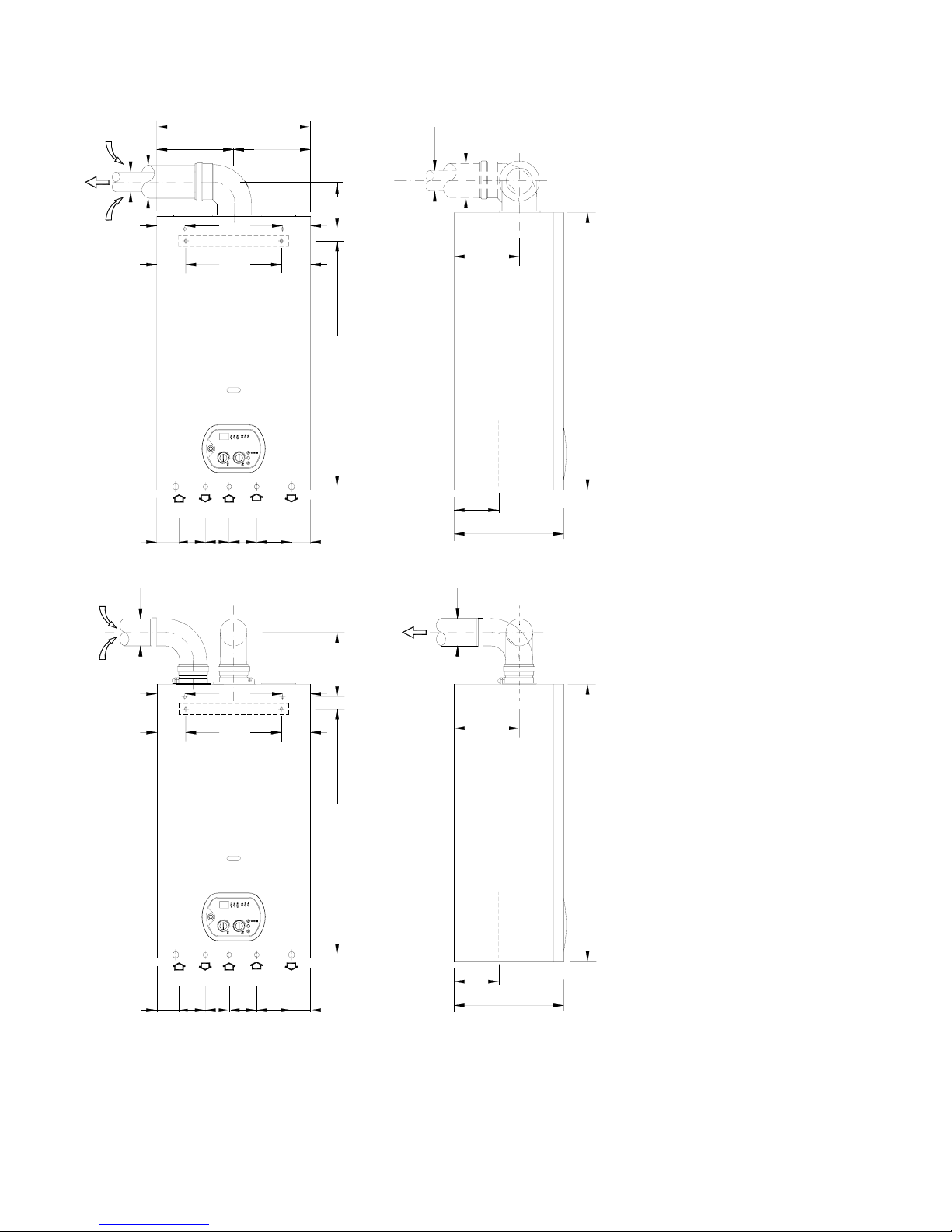
OVERALL DIMENSIONS - EXHAUST FLUE SYSTEM – mod. RSF 24 E
TYPE C WALL-MOUNTED BOILERS
SEALED COMBUSTION CIRCUIT:
kit A
Horizontal coaxial exhaust flue
system with 360° rotation.
It allows the flue exhaust and the air
intake directly to an external wall.
To insert a bend, reduce total flue
EY
URN ¾”
ER ½”
”
t B
e exhaust/emission twin
e
reduce total flue
OTE: USE ORIGINAL RADIANT APPROVED FLUE KIT SYSTEMS, FLUE ACCESSORIES AND FLUE DIAPHRAGMS ONLY.
FLUE KIT
100
60
AFGCR
55.5
65.5 7078 80 102
720
80
85 280 85
82 286 82
19035
55.5
G
65.5R78 70C80F102
A
80
130
320
800
198
320
130
720
85
82
280 85
286 82
= =
450
35 137
800
198
60
100
S
S
length by 0.8 m.
K
R RET
G GAS ½”
C HOT WAT
F COLD WATER ½”
A HEATING FLOW ¾
ki
Doubl
flue system with 360° rotation.
It allows the flue exhaust into a flu
duct and the air intake directly from
an external wall.
To insert a bend,
length by 1.5 m.
N
APPROVED RADIANT FLUE DIAPHRAGMS AND ADJUSTMENT TABLES ARE SUPPLIED WITH RADIANT ORIGINAL
SYSTEMS.
DOMESTIC HOT WATER WITH STORAGE CYLINDER – TA05A027.A0504
6
 Loading...