

Radiant RS 20 E, RS 24 E, RS 30 E Installation And Maintenance Manual
CE
0063 - 0694
ENGLISH
Technical Specification RADIANT BRUCIATORI S.p.A. Montelabbate (PU) ITALY By Technical Department
INSTALLATION,
AND MAINTENANCE MANUAL
FOR GAS FIRED, ONLY HEATING
WALL-HUNG BOILERS
(SYSTEM BOILERS)
Model
RS 20 E - RS 24 E - RS 30 E
TYPE C ROOM SEALED


INDEX
INSTALLATION INSTRUCTIONS AND WARNINGS page 1
TECHNICAL DATA page 2
OVERALL DIMENSIONS - EXHAUST FLUE SYSTEM page 3-4
GENERAL INSTALLATION REQUIREMENTS page 5
BOILER INSTALLATION page 7
ELECTRICAL CONNECTIONS page 9; 15-16
BOILER CONTROL PANEL page 10
STARTING UP THE BOILER FOR THE FIRST TIME page 10
REGULATING THE GAS PRESSURE page 12
MULTIGAS OPERATION page 13
MAIN COMPONENTS page 14
MAINTENANCE page 17
UNPACKING page 17
FAULT FINDING CHART page 18
SHORT LIST OF COMPONENTS page 18

Installation Manual
SYSTEM BOILER – Cod. 99951NA – November 2002
1
THE FRIENDLY POWER OF HEAT
Thank you for choosing RADIANT
Declaration for purposes of Art. 7 of Law 46 of 5 April 1990.
RADIANT BRUCIATORI S.p.A. hereby declares that all of its products are constructed to industry standards as required by the Article in
question and by Article 5 of the law in effect (D.P.R. no. 447/97).
RADIANT BRUCIATORI S.p.A. products are type tested EC.
All RADIANT boilers are constructed according to UNI - CIG (EC) norms. The materials used, such as copper, brass, and stainless steel
form a compact, homogeneous, highly functional unit that is easy to install and simple to operate. The wall-mounted boiler is equipped with
all of the approved accessories required to make it a true, independent heating plant for home heating and for the production of hot water for
domestic needs. All boilers are fully inspected, and come with a certificate of quality signed by the inspector and with a warranty certificate.
This booklet must be read carefully and stored in a safe place, accompanying the boiler at all times.
RADIANT BRUCIATORI S.p.A. declines any and all responsibility for misinterpretations of this booklet deriving from any
translations of same.
RADIANT BRUCIATORI S.p.A. will not be responsible for non-observance of the instructions contained in this booklet or for the
consequences of any action not specifically described herein.
INSTALLATION INSTRUCTIONS - WARNINGS
THIS INSTALLATION, USE, AN D MAINTENANCE MANUAL IS AN ESSENTIAL AND IN TEGRAL PART OF THE PRODUCT, AND MUST ALWAYS BE KEPT NEAR THE DEVICE.
THE WARNINGS CON TAINED IN THIS SECTION ARE ADDRESSED BOT H TO THE USER AND TO INSTALLATION AN D MAINTENANCE PERSONNEL.
THE USER WILL FIND INFORMATION ON OPERATION AND LIMITS OF USE IN THE ACCOMPANYING MANUAL, WHIC H SHOULD BE READ VERY CAREFULLY.
STORE THE MANUAL CAREFULLY FOR FUTURE REFERENCE.
1) GENERAL WARNINGS
INSTALLATION MUST BE PERFORMED IN OBSERVANCE OF CURRENT NORMS, ACCORDING TO THE CONSTRUCTOR’S INSTRUCTIONS, AND BY PROFESSIONALLY QUALIFIED PERSONNEL.
THE INSTALLATION INSTRUCTIONS MANUAL MUST BE ALWAYS ACCOMPANY THE BOILER.
PROFESSIONALLY QUALIFIED PERSONNEL ARE THOSE HAVING TECHNICAL COMPETENCE IN THE SECTOR OF APPLICATION OF THE DEVICE (CIVIL OR INDUSTRIAL), AND, IN PARTICULAR, THE CONSTRUCTOR’S AUTHORISED
SERVICE CENTRES.
INCORRECT INSTALLATION MAY CAUSE DAMAGE TO PERSONS, ANIMALS, OR PROPERTY, FOR WHICH THE CONSTRUCTOR ASSUMES NO LIABILITY.
•
After completely removing the packing, make sure that the contents are in perfect condition.
•
In case of doubt, do not use the equipment. Consult the supplier.
•
Packing materials (cardboard carton, wooden crate, nails, clips, plastic bags, polystyrene, etc.) are potentially dangerous and must be kept away from children.
•
Before performing any cleaning or maintenance operation, turn off the unit by means of the mains switch and/or by means of the appropriate cut-off devices.
•
Do not block the air intake or heat dissipation grates.
•
In the event of breakdown and/or poor functioning of the device, turn it off and do not attempt to repair it or take any direct action. Refer to professionally qualified personnel only.
•
Any repairs must be performed exclusively by a service centre authorised by the constructor, and with original spare parts only.
•
Non-observance of the above instruction may compromise the safety of the device. To guarantee efficient and correct operation, the device should undergo period maintenance by professionally qualified personnel according to the constructor’s
instructions.
•
Whenever the device is to be put out of service, secure all potentially hazardous parts to prevent accidents or damage.
•
If the device is sold or transferred to another owner, or if you move and leave the boiler, make sure that this booklet stays with the boiler so that it may be consulted by the new owner and/or by the installer.
•
Use only original spare parts for all devices with optionals or kits (including electrical ones).
WARNING: this device must be used for its intended purpose, i.e., heating and production of domestic hot water. Any other use is improper and therefore dangerous. The constructor will have no contractual or extracontractual liability for damage caused by
incorrect installation and/or use or by non-observance of instructions supplied by the constructor.
This device must be used exclusively with a sealed central heating system equipped with an expansion vessel.
2) WARNINGS REGARDING INSTALLATION
Warranty expires 12 months from date of installation and in all cases no later than 18 months from date of construction. First start-up must be performed by authorised personnel only. For any operation on the hydraulic, gas, or electrical circuit regarding the
heating unit, refer to authorised technicians only and use original spare parts only. Wall-mounted boilers are not to be installed in damp rooms, and must be protected against sprays or jets of water or other liquids to prevent malfunctions of the electrical and
heating devices. They must not be exposed to direct steam from cookers, and nothing must be placed on top of them. This heating unit has been constructed to heat the home and to produce hot water. The constructor declines all responsibility for incorrect
installation and/or use of the device. Do not leave the device on when it is not being used: close the gas cock and turn off the mains switch. If you smell gas in the room in which the device is installed, do not operate any electrical switches, telephones, or any
other device that might cause a spark. Immediately open doors and windows to create an air current to clear the room. Close the main gas cock (at the meter) or the cylinder cock, and request immediate technical service.
Do not tamper with the device.
SYSTEMS WITH THERMOSTATS
A by-pass must be installed in heating systems with radiators thermostats.
As required by current norms, these devices must be installed by qualified personnel only, who must respect norms UNI-CIG 7129 and 7131 and revisions, fire department regulations, and requirements of the local gas company. Before installing the boiler,
make sure that the water and heating systems are compatible with its output. The room must be properly ventilated by means of an air intake (see UNI 7129/92 and UNI 7129/95 FA).
The air intake must be at floor level open flue only, at a point where it cannot be obstructed, and protected by a grate that does not reduce the useful section of flow.
The use of air flows from adjacent rooms is permitted as long as such rooms are in depression with respect to the outside and as long as there are no wood-burning fireplaces or fans installed there. If the boiler is to be installed externally (for example, on
balconies or terraces), make sure that it is protected against atmospheric agents to prevent damage to components and voiding of the warranty. In such cases we recommend building a heat compartment to protect the boiler against inclement weather.
Check the technical data on the packing and on the plate located inside the front casing. Check that the burner is suitable for use with the type of gas available.
Make sure that all pipes and connections are perfectly sealed and that there are no gas leaks.
All pipework should be chemically flushed to remove any residues that might negative effect the operation of the boiler.
3) GENERAL WARNINGS BASED ON TYPE OF POWER SUPPLY
POWER SUPPLY
Electrical safety is achieved only when the device is correctly and efficiently earthed as per current safety norms (IEC 64-8 Electrical Part).
•
This fundamental safety requirement must be checked. In case of doubt, request a check of the electrical system by professionally qualified personnel. The constructor will not be liable for any damage caused by lack of or improper earthing of the
system.
•
Have professionally qualified personnel check that the electrical system is adequate for the maximum absorbed power of the device (indicated on the plate). In particular, make sure that the section of the system wires is suitable for the maximum
absorbed power of the device.
•
Do not use adapters, multiple sockets, and/or extension cords to power the device from the electrical mains.
•
Provide a unipolar switch as required by current safety regulations to connect the device to the mains.
•
The use of any electrical device requires the observance of some fundamental rules, such as:
•
do not touch the device with wet or damp parts of the body and/or with bare feet
•
do not pull on electrical cables
•
do not expose the device to atmospheric agents (rain, sun, etc.) unless specifically provided for
•
do not allow the device to be used by children or anyone unfamiliar with its operation
•
The power cable must not be replaced by the user.
•
If the cable becomes damaged, turn off the device and have the cable replaced by professionally qualified personnel only.
•
If you decide not to use the device for an extended length of time, turn off the mains switch that feeds all components of the system using electrical energy (pumps, burner, etc.).
Installation Manual
SYSTEM BOILER – Cod. 99951NA – November 2002
2
TECHNICAL DATA
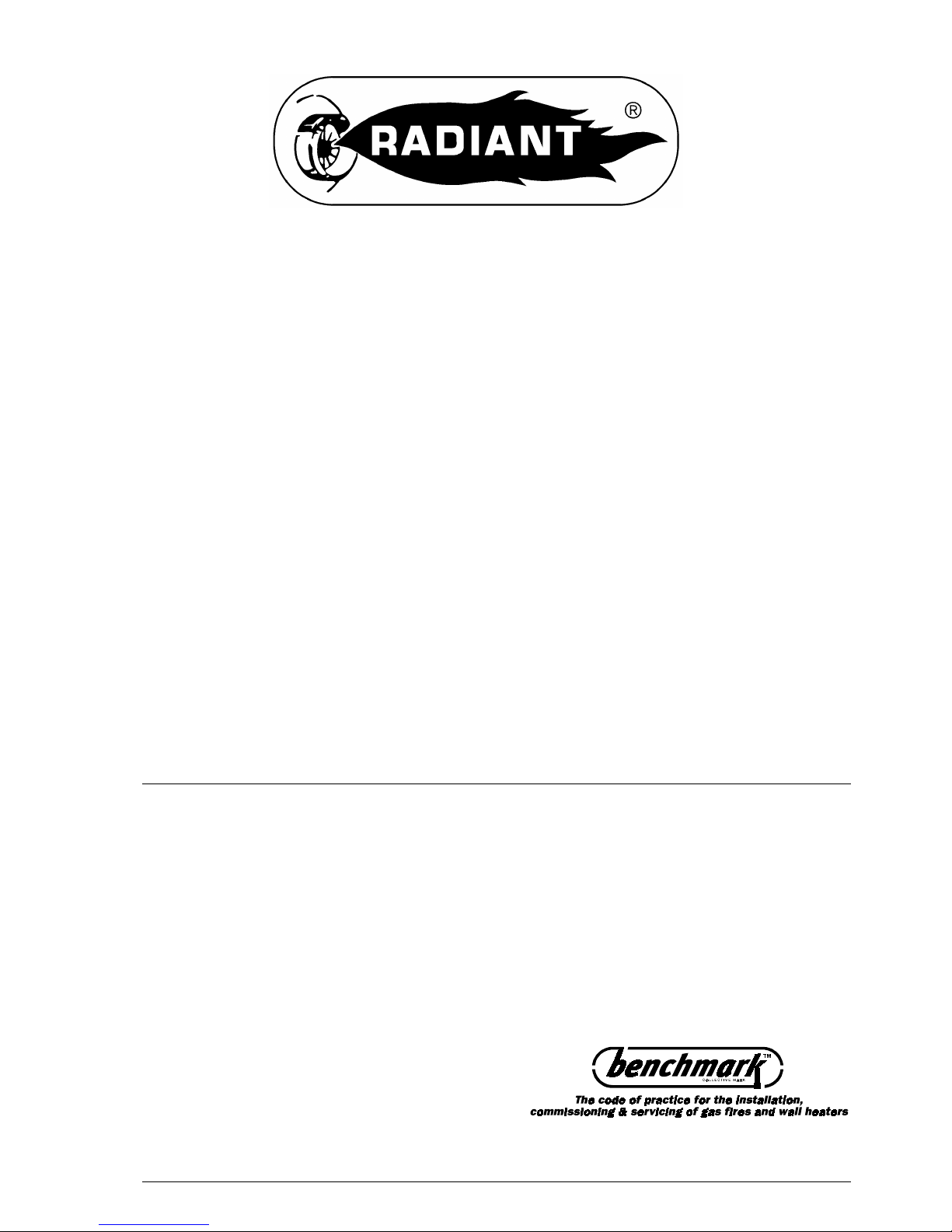
Type C devices are devices in which the combustion circuit (air intake,
combustion chamber, exchanger, combustion exhaust) is sealed off from the
place where they are installed.
CENTRAL HEATING
sealed combustion circuit type
Technical data
MODELS
RS 20 E RS 24 E RS 30 E
Maximum rated input KCal/h 22900 25628 29670
Kw 26.60 29.8 34.50
BTU/hr 90867 101692 117731
Minimum rated input KCal/h 11000 15000 16340
Kw 12.80 17.5 19
BTU/hr 43648 59520 64837
Maximum working output KCal/h 20900 23090 27440
Kw 24.34 26.85 31.90
BTU/hr 82931 91621 108882
Minimum working output KCal/h 9450 12900 14560
Kw 11 15 16.90
BTU/hr 37498 51187 57774
Max. working pressure (heating) bar 3 3 3
Max. working pressure (water) bar 6 6 6
Min. working pressure (heating) bar 0.3 0.3 0.3
Max. heating temperature °C 80 80 80
Expansion vessel capacity (initial pressure 1 bar) Litres 6 6 10
Width mm. 450 450 450
Height mm. 790 790 790
Depth mm. 320 320 320
Weight Kg. 42 42 45
Flue diameter Ø
100/60
80/80
100/60
80/80
125/80
80/80
Flow/return connections Ø ¾” ¾” ¾”
Cold water connections Ø ½” ½” ½”
Hot water connections Ø -
Gas connections Ø ½” ½” ½”
Electrical connection 50 Hz V 230 230 230
Power supply W 150 150 150
Burner jets NP 13 G20 Ø 1.25 1.25
Burner jets NP 13 G30 Ø 0.75 0.77
Burner jets NP 17 G20 Ø 1.20
Burner jets NP 17 G30 Ø 0.75
Gas category:
IT II2H3
Gas supply pressure:
G20
20 mbar /
G30/31
29-30/37 mbar
FORCED CIRCULATION
Coaxial vertical
Coaxial horizontal
C32
C12
C52 Double
Installation Manual
SYSTEM BOILER – Cod. 99951NA – November 2002
3
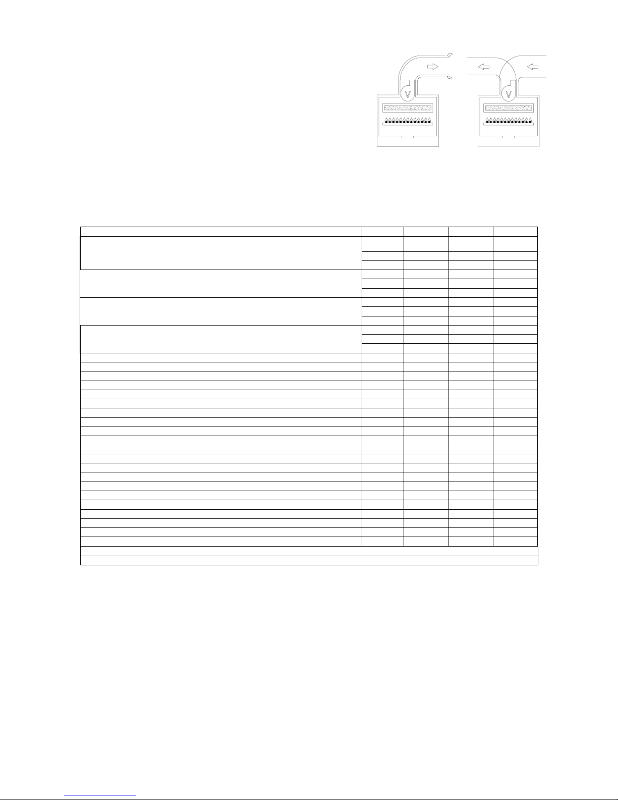
TYPE C WALL-MOUNTED
BOILERS
SEALED COMBUSTION CIRCUIT:
Kit A.
Horizontal coaxial exhaust flue
system with 360° rotation. It allows
the flue exhaust and the air intake
directly to an external wall. .
N.B.: To insert a bend in the flue,
reduce total flue length by 0.8 m.
Kit B.
Double exhaust/emission twin flue
system with 360° rotation. It allows
the flue exhaust into a flue duct and
the air intake directly from an
external wall.
N.B.: To insert a bend in the flue,
reduce total flue length by 1.5 m.
R
RETURN ¾”
G
GAS 1/2"
F
COLD WATER INLET 1/2"
A
HEATING FLOW ¾”
NOTE:
USE ORIGINAL RADIANT APPROVED FLUE KIT SYSTEMS, FLUE ACCESSORIES AND FLUE DIAPHRAGMS ONLY.
APPROVED RADIANT FLUE DIAPHRAGMS AND ADJUSTMENT TABLES ARE SUPPLIED WITH RADIANT ORIGINAL FLUE KIT
SYSTEMS.
10151
R G
46
F
101
A
790
948
RG F A
120
80
10151 46
80
101
790
894
24
125
320
17
790
924
125
182
80
320
1724
790
870
60
450
100
= =
100
182
60
Installation Manual
SYSTEM BOILER – Cod. 99951NA – November 2002
4
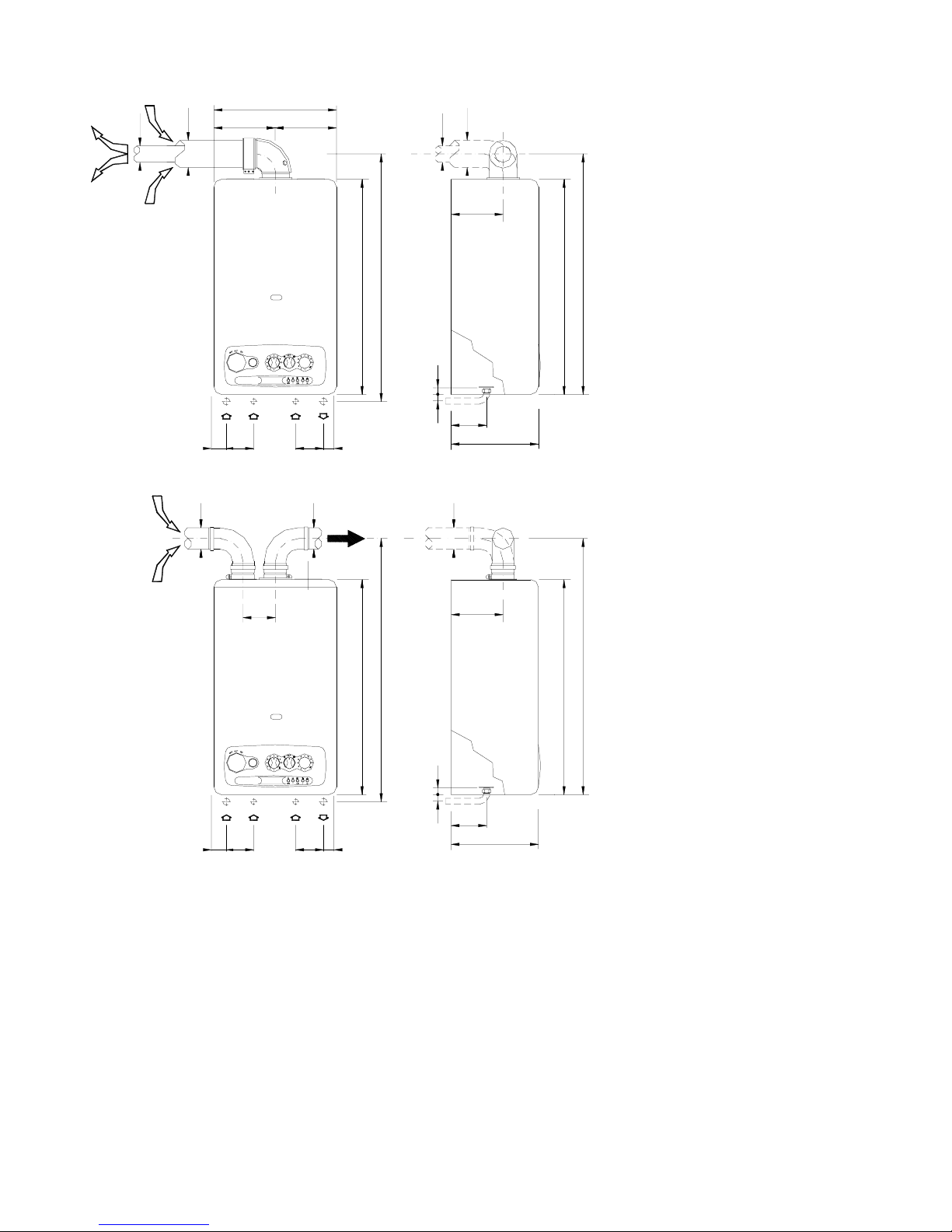
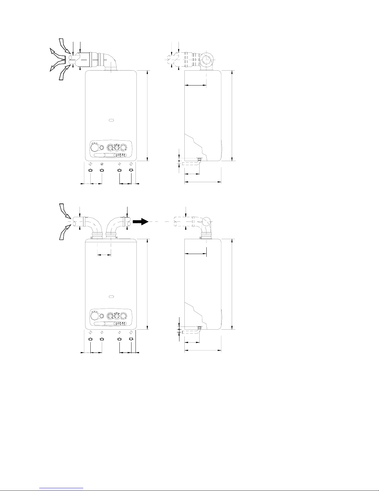
TYPE C WALL-MOUNTED
BOILERS
SEALED COMBUSTION
CIRCUIT:
Kit G.
Horizontal coaxial exhaust
flue system with 360° rotation.
It allows the flue exhaust and
the air intake directly to an
external wall. .
N.B.: To insert a bend in the
flue, reduce total flue length by
0.8 m.
Kit B.
Double exhaust/emission twin
flue system with 360° rotation.
It allows the flue exhaust into a
flue duct and the air intake
directly from an external wall.
N.B.: To insert a bend in the
flue, reduce total flue length by
1.5 m.
R
RETURN ¾”
G
GAS 1/2"
F
COLD WATER INLET 1/2"
A
HEATING FLOW ¾”
NOTE:
USE ORIGINAL RADIANT APPROVED FLUE KIT SYSTEMS, FLUE ACCESSORIES AND FLUE DIAPHRAGMS ONLY.
APPROVED RADIANT FLUE DIAPHRAGMS AND ADJUSTMENT TABLES ARE SUPPLIED WITH RADIANT ORIGINAL FLUE KIT
SYSTEMS.
RG F A
10151 101 46
120
80
80
10151
GR
46101
F A
80
125
125
24 17
320
182
790
790
80
125
24 17
320
182
790
790
125
80

Installation Manual
SYSTEM BOILER – Cod. 99951NA – November 2002
5
GENERAL INSTALLATION REQUIREMENTS
GAS SAFETY
It is the law that all gas appliances are installed by a CORGI registered installer (you can check this by contacting corgi on 01256.372200) in
accordance with the regulations listed below. Failure to install appliances correctly could lead to prosecution. It is in your own interest and
that of safety to ensure that the law is complied with. Failure to have your appliance installed to comply with the installation instructions and
the requirements listed below could invalidate your guarantee.
RELATED DOCUMENTS
The installation of the boiler must be in accordance with the relevant requirements of the Gas Safety regulations, Building regulations, I.E.E.
regulations and the bylaws of the local water authority.
It should be in accordance also with any relevant requirements of the local authority and the relevant recommendations of the following
British Standard Codes of Practice:
B.S 6400: 1985 & B.S. 6891 : 1988.
BS 5376: Selection and Installation of Gas Space Heating ( 1 and 2 family gases)
Part 2: Boilers of rated input not exceeding 60 Kw
BS 5449: Central Heating for domestic premises
Part 1: Forced circulation Hot Water System
CP 342: Centralised Hot Water Supply BS 6700 : 1987
Part 2: Buildings other than individual
BS 5440: Flues and air supply for Gas Appliances of rated input not exceeding
60 Kw (1 and 2 family gases)
Part 1: Flues
Part 2: Air Supply
BS 5446: 1990: Installation of Gas Hot Water supplies for domestic purposes
GAS SUPPLY
Service Pipes: The local gas region should be consulted at the installation planning stage in order to establish the availability of supply of
gas. An existing service pipe must not be used without prior consultation with the local gas region.
Meters: A gas meter is connected to the service pipe by the local gas region or local gas region contractor. An existing meter should be
checked to ensure that it is capable of passing an additional 3.4 m3/hr (125 ft/hr) before the appliance is installed. The meter outlet
governor should ensure a nominal dynamic pressure of 20m Bar, (8 in wg) at the boiler. Installation pipes should be fitted in accordance with
BS6891.1988.
Pipework that supplies the boiler must be a 22 mm. ininterrupted supply from meter to the isolation cock of the
boiler.
The complete installation must be tested for soundness as described in the above code, BS 6400: 1985 & BS6891.
IMPORTANT: BOTH THE USER AND THE MANUFACTURER RELY UPON THE INSTALLER, WHOSE JOB IS TO INSTALL THE BOILER
AND CONNECT IT TO A CORRECTLY DESIGNED HEATING SYSTEM. THE INSTALLER SHOULD ACQUAINT HIMSELF WITH THE
CONTENTS OF THIS PUBLICATION AND THE RELEVANT BRITISH STANDARDS CONCERNING INSTALLATION REQUIREMENTS.
LOCATION OF BOILER
In siting the combination boiler, the following limitations MUST be observed:
The position selected for installation should be within the building, and MUST allow
adequate space for installation, servicing and operation of the combination boiler, and for air circulation around it. The boiler is not suitable
for external installation.
This position MUST also allow for a suitable flue termination to be made. The boiler must be installed on a flat vertical wall which is capable
of supporting the weight of the combination boiler, and any ancillary equipment.
If the boiler is to be fitted in a timber framed building it should be fitted in accordance with the British Gas publication "Guide for Gas
Installations in Timber Frame Housing, Reference IGE/UP/6. If in doubt, advice must be sought from the local region of British Gas.
The boiler may be installed in any room or internal space, although particular attention is drawn to the requirements of the current I.E.E.
Wiring Regulations, and in Scotland the electrical provisions of the Building Regulations applicable in Scotland, with respect to the
installation of the boiler in a room or internal space containing a bath or shower.
Where a room-sealed appliance is installed in a room containing a bath or shower, any electrical switch or appliance control utilising mains
electricity must be so situated that it cannot be touched by a person using the bath or shower.
A compartment used to enclose the combination boiler MUST be designed and constructed specifically for this purpose. An existing
cupboard, or compartment, may be used provided it is modified accordingly.
Where installation will be in an unusual location, special procedures may be necessary. BS 6798 gives detailed guidance on this aspect.
For clearances to be made available for installation and servicing, see Sections 5.2.2. to 5.2.4.
Installation Manual
SYSTEM BOILER – Cod. 99951NA – November 2002
6
FLUE POSITION
IMPORTANT: THE FLUE SYSTEM SHALL BE INSTALLED IN ACCORDANCE WITH THE RECOMMENDATIONS CONTAINED IN BS
5440:1.
The boiler MUST be installed so that the terminal is exposed to the external air.
It is important that the position of the terminal allows free passage of air across it at all times.
If the terminal discharges into a pathway or passageway check that combustion products will not cause nuisance and that the terminal will
not obstruct the passageway.
In certain weather conditions a terminal may emit a plume of steam. Positions where this would cause a nuisance should be avoided.
IMPORTANT REQUIREMENT: The correct dimensional relationship between the terminal and any obstruction, openable window or
ventilator as shown in Fig 1 pag.7 It is ESSENTIAL TO ENSURE, in practice, that products of combustion discharging from the terminal
cannot re-enter the building, or any other adjacent building, through ventilators, windows, doors, other sources of natural air infiltration, or
forced ventilation/air conditioning systems. If this should occur, the appliance MUST BE TURNED OFF IMMEDIATELY and the local gas
region consulted.
Where the lowest part of the terminal is fitted less than 2m (6.6ft) above a balcony, above ground, or above a flat roof to which people have
access, the terminal MUST be protected by a purpose designed guard.
Where the terminal is fitted within 850mm (34in) of a plastic or painted gutter, or 450mm (18in) of painted eaves, an aluminium shield of at
least 1000 mm (40in) long should be fitted to the underside of the gutter painted surface.
The air inlet/products outlet duct and the terminal of the boiler MUST NOT be closer than 25mm (1in) to combustible material.
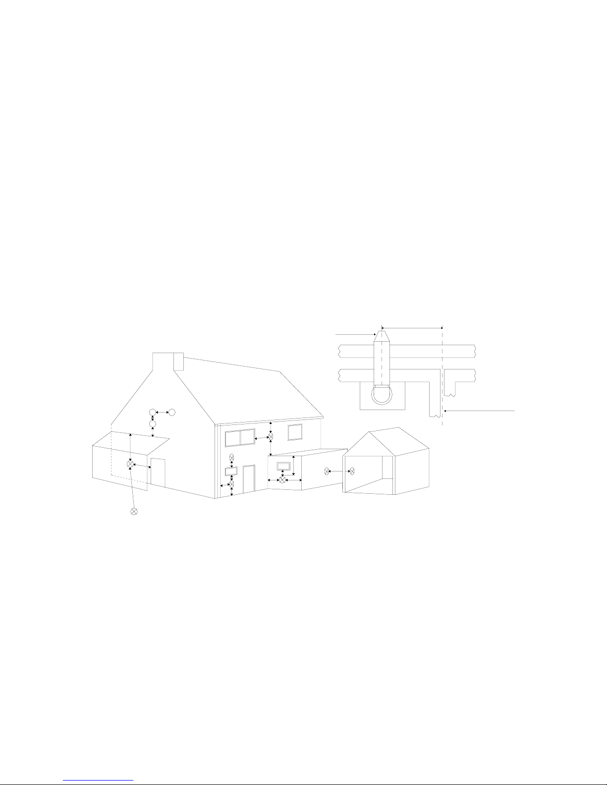
TERMINAL POSITION
J
E
A
G
M
F F
A
D
H,I
TOP VIEW REAR FLUE
D
G
L
K
G
N
B.C
TERMINAL
ASSEMBLY
PROPERTY BOUNDARY LINE
300 min
A
Directly below an openable window, air vent or any other ventilation opening. 300 mm
B
Below gutter, drain pipes or soil pipes. 25 mm
C
Below eaves. 25 mm
D
Below balcony or carport roof. 25 mm
E
From vertical drain pipes or soil pipes. 25 mm
F
From internal or external corners. 25 mm
G
Above adjacent ground, roof or balcony level. 300 mm
H
From a surface facing the terminal. 600 mm
I
Facing the terminals. 1200 mm
J
From opening (door, window)in the carport into dwelling. 1200 mm
K
Vertically from a terminal on the same wall 1500 mm
L
Horizontally from a terminal on the same wall 300 mm
M
Above an opening, air brick, opening window etc. 300 mm
N
Horizontally to an opening, air brick, opening window etc. 300 mm
Fig. 1
 Loading...