

Radiant RMA, RMAS Installation, Use And Maintenance Manual
CE
0694
ENGLISH
Technical Specification RADIANT BRUCIATORI S.p.A. Montelabbate (PU) ITALY By Technical Department
INSTALLATION, USE,
AND MAINTENANCE MANUAL
FOR GAS FIRED, WALL-HUNG BOILERS
WITH DOMESTIC HOT WATER
STORAGE CYLINDER
Model
RMA
TYPE B OPEN COMBUSTION CHAMBER
Model
RMAS
TYPE C ROOM SEALED


INDEX
USER MANUAL page I-II
INSTALLATION INSTRUCTIONS AND WARNINGS page 2
INSTALLATION REQUIREMENTS page 3
OVERALL DIMENSIONS - EXHAUST FLUE SYSTEM page 4
GENERAL INSTALLATION REQUIREMENTS page 6
BOILER INSTALLATION page 8
ELECTRICAL CONNECTIONS page 10;19-22
BOILER CONTROL PANEL page 11
STARTING UP THE BOILER FOR THE FIRST TIME page 11
BOILER ADJUSTMENTS page 13
MULTIGAS OPERATION page 14
REGULATING THE GAS PRESSURE page 15
TECHNICAL DATA page 16
MAINTENANCE page 24
UNPACKING page 24
FAULT FINDING CHART page 25
SHORT LIST OF COMPONENTS page 26
User Manual
Wall Hung Boiler with D.H.W. Storage Cylinder Low Nox – Cod. 99881NA – July 2001
I
BOILER OPERATION AND ADJUSTMENT PROCEDURES FOR USER
Before turning on the boiler read the following warnings carefully .
Make sure that the warranty booklet carries the stamp of the authorised technician responsible for installing the boiler.
Installation, starting up for the first time, adjustments and maintenance operations must all be carried out solely by qualified
technicians. Incorrect installation may cause damage to persons, animals or property for which the manufacturer cannot be held
liable.
WARNING!
⇒ Do not start the boiler unless you are sure it has been thoroughly tested by an authorised technician.
⇒ Check that the regulations regarding air intakes and ventilation of the room where the boiler is installed have been
fully complied with (see installation instructions pag.2).
⇒ The anti-freeze system will come into operation only if the boiler is in the winter (!!!!) or summer ("""") position (with
selector switch 1 in fig. 1 turned to the summer or winter position) and the gas supply turned on. The manufacturer
can accept no responsibility for damage to the boiler caused by lack of observation of these requirements.
⇒ If the boiler should freeze up, under no circumstances attempt to turn it on but call the service centre immediately.
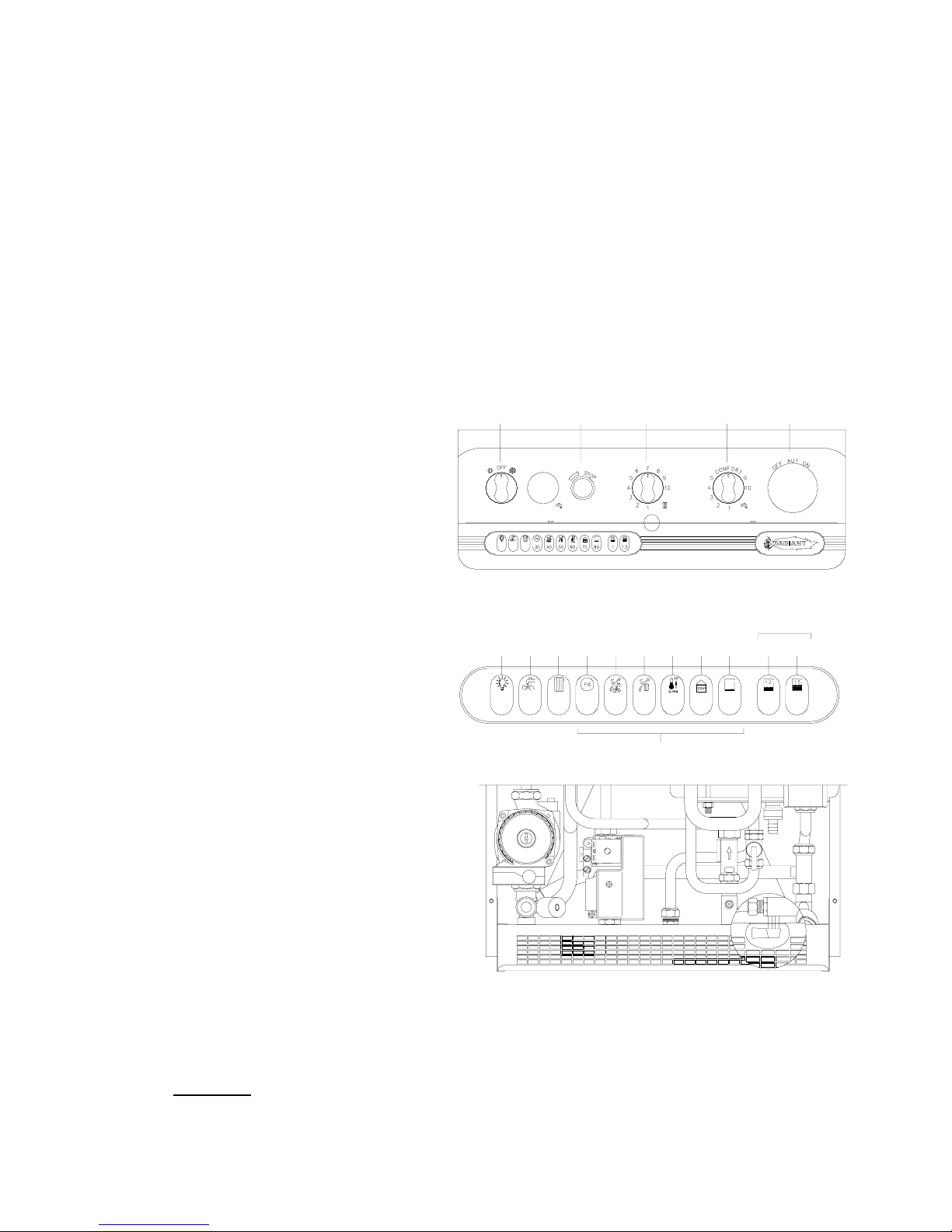
LEGEND
(see fig. 1)
1.
SUMMER-WINTER ON-OFF SWITCH
2.
LOCK-OUT INDICATOR
3.
HEATING TEMPERATURE ADJUSTMENT KNOB
4.
WATER TEMPERATURE ADJUSTMENT KNOB
5.
SPACE FOR ADDING AN OPTIONAL TIMER
SELF- DIAGNOSTIC LEGEND
(see fig. 2)
6.
OPERATING/ POWER INDICATOR
7.
DOMESTIC HOT WATER OPERATION
8.
HEATING OPERATION
9.
FLASHING LIGHT DENOTING AIR PRESSURE
SWITCH FAILURE
10.
FLASHING LIGHT DENOTING DOMESTIC WATER
SENSOR FAILURE
11.
FLASHING LIGHT DENOTING HEATING SENSOR
FAILURE
12.
FLASHING LIGHT DENOTING 90° C MAX
TEMPERATURE SENSOR FAILURE
13.
FLASHING LIGHT DENOTING FLUE SAFETY THERMOSTAT FAILURE
14.
FLASHING LIGHT DENOTING LACK OF WATER IN
SYSTEM
15.
WATER PRESSURE LEVEL 1 BAR
16.
WATER PRESSURE LEVEL 1.5 BAR
17.
ELECTRONIC TEMPERATURE INDICATOR
Turning on the electronic ignition:
# turn on the gas cock situated under the boiler grill;
# turn selector switch 1 to the ! symbol denoting winter (see
fig.2);
#
make sure that 6 light is ON (see fig. 2) and the no.15 or
no.16 lights are ON (see fig. 2); if light no.14 flashes, it
means water deficiency in the system: open the filling tap
located ander the boiler (see fig. 3) and fill the system until
a pressure of 1.5 bar has been reached (light no.16 ON; see fig. 2) and then close the filling tap.
# The automatic ignition system will turn the burner on.
It may be necessary to repeat the procedure a few times to purge air from the pipes. To repeat the ignition procedure press
release button 2 (see fig.1) and then try the ignition procedure once again. If the boiler does not start, press the reset button 2
(see fig. 1). IMPORTANT
should the boiler fail to ignite wait 3 minutes before pressing button again.
If locking-out persists, turn boiler OFF and call an authorised radiant service engineer.
Fig. 3
6
7
1
17
1089
11 12
13
14
15 16
23 4
5
5030 40 60 70 80
1
1.5
PRESSURE GAUGE
ELECTRONIC WATER
SELF DIAGNOSTIC
Fig. 1
Fig. 2

User Manual
Wall Hung Boiler with D.H.W. Storage Cylinder Low Nox – Cod. 99881NA – July 2001
II
Turning on procedure for electronic ignition (only for U.k. and Ireland):
# turn on the gas cock situated under the boiler grill;
# turn selector switch 1 to the ! symbol denoting winter (see fig.2);
# make sure that 6 light is ON (see fig. 2 pag. I) and the no.15 or no.16 lights are ON (see fig. 2 pag. I); if light no.14 flashes, it
means water deficiency in the system: open the tap on the filling loop and fill the system until a pressure of 1.5 bar has been
reached (light no.16 ON; see fig. 2 pag. I) and then close the tap.
# The automatic ignition system will turn the burner on.
It may be necessary to repeat the procedure a few times to purge air from the pipes. To repeat the ignition procedure press
release button 2 (see fig. 1 pag. I) and then try the ignition procedure once again. If the boiler does not start, press the reset
button (see fig. 1 pag. I). IMPORTANT
should the boiler fail to ignite wait 3 minutes before pressing button again.
If locking-out persists, turn boiler OFF and call an authorised service engineer.
Turning off boilers with electronic ignition :
# turn selector switch 1 to the OFF position;;
# if the boiler will not be used for long periods it is recommended that the gas cock under the boiler grill be shut off.
THE BOILER IN USE
Summer-winter use (see fig. 1 pag. I).
# turn the selector switch 1 to the ! program to operate the boiler in the WINTER position for both heating and hot water;
# turn the selector switch 1 to the " program to operate the boiler in the SUMMER position for just hot water;
# if the system has a room thermostat, set this to the temperature required (the law states 20°C).
REGULATING THE HEATING TEMPERATURE
The heating temperature is regulated by turning knob 3 (see fig. 1 pag. I).
# turn it counter-clockwise to lower the temperature.
# turn it clockwise to raise the temperature.
# the temperature range can be adjusted from a minimum of 30°C to a maximum of 80°C.
REGULATING THE HOT WATER TEMPERATURE
The hot water temperature is regulated by turning knob 4 (see fig. 1 pag. I).
# turn it counter-clockwise to lower the temperature
# turn it clockwise to raise the temperature
# the temperature range can be adjusted from a minimum of 35°C to a maximum of 60°C.
WARNINGS FOR THE USER
To keep the boiler in efficient and safe operating condition, carefully follow the instructions listed below:
# Have normal maintenance performed at least once a year by one of our authorised service centres (a fee will be charged),
combustion tests are necessary every two years and should again be carried out by a qualified Radiant technician (in
accordance with D.P.R. 412 regulations, 26-08-93).
# Periodically check system pressure on the pressure gauge and check that pressure is between 0.5 - 1.5 bar with the system
cold.
# Do not clean the casing or internal parts of the boiler with reducing agents or solvents. Clean only with soap and water.
# Never leave flammable materials in the immediate vicinity of the boiler.
# For greater comfort and more rational use of heat, it is advisable to install a room thermostat connected to a clock timer to
turn the boiler on and off during the course of the day or week (in accordance with D.P.R. 412 regulations, 26-08-93).
# The boiler is equipped with an anti-freeze system, which is operative with switch 1 in either SUMMER " or WINTER !
position, even if the room thermostat is set at zero, as long as there is electrical power and gas feed.
FLUE SAFETY
Natural draft boilers are equipped with a device that controls correct evacuation of exhaust fumes. This device guarantees
maximum safety during operation. If the flue is partially or completely obstructed, or if its section is insufficient for evacuation of
exhaust fumes, the device will intervene and block the flow of gas to the main burner and to the pilot light, turning off the boiler.
If this occurs, contact an authorised technician , close the gas tap and turn electrical mains off.
Do not tamper with the device in any way.
Installation Manual
Wall Hung Boiler with D.H.W. Storage Cylinder Low Nox – Cod. 99881NA – July 2001
1
THE FRIENDLY POWER OF HEAT
Thank you for choosing RADIANT
Declaration for purposes of Art. 7 of Law 46 of 5 April 1990.
RADIANT BRUCIATORI S.p.A. hereby declares that all of its products are constructed to industry standards as required by the
Article in question and by Article 5 of the law in effect (D.P.R. no. 447/91).
RADIANT BRUCIATORI S.p.A. products are type tested EC.
All RADIANT boilers are constructed according to UNI - CIG (EC) norms. The materials used, such as copper, brass, and
stainless steel, form a compact, homogeneous, highly functional unit that is easy to install and simple to operate. The wallmounted boiler is equipped with all of the approved accessories required to make it a true, independent heating plant for home
heating and for the production of hot water for domestic needs. All boilers are fully inspected, and come with a certificate of
quality signed by the inspector and with a warranty certificate. This booklet must be read carefully and stored in a safe place
near the boiler.
RADIANT BRUCIATORI S.p.A. declines any and all responsibility for misinterpretations of this booklet deriving from
any translations of same.
RADIANT BRUCIATORI S.p.A. will not be responsible for non-observance of the instructions contained in this booklet
or for the consequences of any action not specifically described herein.

Installation Manual
Wall Hung Boiler with D.H.W. Storage Cylinder Low Nox – Cod. 99881NA – July 2001
2
INSTALLATION INSTRUCTIONS
WARNINGS
THIS INSTALLATION, USE, AND MAINTENANCE MANUAL IS AN ESSENTIAL AND INTEGRAL PART OF THE PRODUCT, AND MUST ALWAYS BE KEPT NEAR THE
DEVICE.
THE WARNINGS CONTAINED IN THIS SECTION ARE ADDRESSED BOTH TO THE USER AND TO INSTALLATION AND MAINTENANCE PERSONNEL.
THE USER WILL FIND INFORMATION ON OPERATION AND LIMITS OF USE IN THE ACCOMPANYING MANUAL, WHICH SHOULD BE READ VERY CAREFULLY.
STORE THE MANUAL CAREFULLY FOR FUTURE REFERENCE.
1) GENERAL WARNINGS
Installation must be performed in observance of current norms, according to the constructor’s instructions, and by professionally qualified personnel.
Professionally qualified personnel are those having technical competence in the sector of application of the device (civil or industrial), and, in particular, the constructor’s
authorised service centres.
Incorrect installation may cause damage to persons, animals, or property, for which the constructor assumes no liability.
• After completely removing the packing, make sure that the contents are in perfect condition.
• In case of doubt, do not use the equipment. Consult the supplier.
• Packing materials (cardboard carton, wooden crate, nails, clips, plastic bags, polystyrene, etc.) are potentially dangerous and must be kept away from children.
• Before performing any cleaning or maintenance operation, turn off the unit by means of the mains switch and/or by means of the appropriate cut-off devices.
• Do not block the air intake or heat dissipation grates.
• In the event of breakdown and/or poor functioning of the device, turn it off and do not attempt to repair it or take any direct action. Refer to professionally qualified personnel
only.
• Any repairs must be performed exclusively by a service centre authorised by the constructor, and with original spare parts only.
• Non-observance of the above instruction may compromise the safety of the device. To guarantee efficient and correct operation, the device should undergo period
maintenance by professionally qualified personnel according to the constructor’s instructions.
• Whenever the device is to be put out of service, secure all potentially hazardous parts to prevent accidents or damage.
• If the device is sold or transferred to another owner, or if you move and leave the boiler, make sure that this booklet stays with the boiler so that it may be consulted by the
new owner and/or by the installer.
• Use only original spare parts for all devices with optionals or kits (including electrical ones).
WARNING: this device must be used for its intended purpose, i.e., heating and production of domestic hot water. Any other use is improper and therefore dangerous. The
constructor will have no contractual or extracontractual liability for damage caused by incorrect installation and/or use or by non-observance of instructions supplied by the
constructor.
This device must be used exclusively with a sealed central heating system equipped with an expansion vessel.
2) WARNINGS REGARDING INSTALLATION
Warranty expires 12 months from date of installation and in all cases no later than 18 months from date of construction. First start-up must be performed by authorised
personnel only. For any operation on the hydraulic, gas, or electrical circuit regarding the heating unit, refer to authorised technicians only and use original spare parts only.
Wall-mounted boilers are not to be installed in damp rooms, and must be protected against sprays or jets of water or other liquids to prevent malfunctions of the electrical and
heating devices. They must not be exposed to direct steam from cookers, and nothing must be placed on top of them. This heating unit has been constructed to heat the home
and to produce hot water. The constructor declines all responsibility for incorrect installation and/or use of the device. Do not leave the device on when it is not being used:
close the gas cock and turn off the mains switch. If you smell gas in the room in which the device is installed, do not operate any electrical switches, telephones, or any other
device that might cause a spark. Immediately open doors and windows to create an air current to clear the room. Close the main gas cock (at the meter) or the cylinder cock,
and request immediate technical service.
Do not tamper with the device.
SYSTEMS WITH THERMOSTATS
A by-pass must be installed in heating systems with radiators thermostats.
As required by current norms, these devices must be installed by qualified personnel only, who must respect norms UNI-CIG 7129 and 7131 and revisions, fire department
regulations, and requirements of the local gas company. Before installing the boiler, make sure that the water and heating systems are compatible with its output. The room
must be properly ventilated by means of an air intake (see UNI 7129/92 and UNI 7129/95 FA).
The air intake must be at floor level open flue only, at a point where it cannot be obstructed, and protected by a grate that does not reduce the useful section of flow.
The use of air flows from adjacent rooms is permitted as long as such rooms are in depression with respect to the outside and as long as there are no wood-burning fireplaces
or fans installed there. If the boiler is to be installed externally (for example, on balconies or terraces), make sure that it is protected against atmospheric agents to prevent
damage to components and voiding of the warranty. In such cases we recommend building a heat compartment to protect the boiler against inclement weather.
Check the technical data on the packing and on the plate located inside the front casing. Check that the burner is suitable for use with the type of gas available.
Make sure that all pipes and connections are perfectly sealed and that there are no gas leaks.
We recommend that the pipes be cleaned out to remove any residues that might negatively affect the operation of the boiler.
3) GENERAL WARNINGS BASED ON TYPE OF POWER SUPPLY
POWER SUPPLY
Electrical safety is achieved only when the device is correctly and efficiently earthed as per current safety norms (IEC 64-8 Electrical Part).
• This fundamental safety requirement must be checked. In case of doubt, request a check of the electrical system by professionally qualified personnel. The constructor will
not be liable for any damage caused by lack of or improper earthing of the system.
• Have professionally qualified personnel check that the electrical system is adequate for the maximum absorbed power of the device (indicated on the plate). In particular,
make sure that the section of the system wires is suitable for the maximum absorbed power of the device.
• Do not use adapters, multiple sockets, and/or extension cords to power the device from the electrical mains.
• Provide a unipolar switch as required by current safety regulations to connect the device to the mains.
• The use of any electrical device requires the observance of some fundamental rules, such as:
• do not touch the device with wet or damp parts of the body and/or with bare feet
• do not pull on electrical cables
• do not expose the device to atmospheric agents (rain, sun, etc.) unless specifically provided for
• do not allow the device to be used by children or anyone unfamiliar with its operation
• The power cable must not be replaced by the user.
• If the cable becomes damaged, turn off the device and have the cable replaced by professionally qualified personnel only.
• If you decide not to use the device for an extended length of time, turn off the mains switch that feeds all components of the system using electrical energy (pumps, burner,
etc.).
Installation Manual
Wall Hung Boiler with D.H.W. Storage Cylinder Low Nox – Cod. 99881NA – July 2001
3
TECHNICAL DATA
Type B unit
Type B boilers have open combustion chambers, and must be connected to a
flue duct to convey combustion exhaust out of the room. Air for combustion is
taken directly from the room in which the boilers are installed.
Type C unit
Type C devices are devices in which the combustion circuit (air intake,
combustion chamber, exchanger, combustion exhaust) is sealed off from the
place where they are installed.
CENTRAL HEATING - DOMESTIC HOT WATER
open combustion circuit type
RMA 21 E
- electronic ignition
CENTRAL HEATING - DOMESTIC HOT WATER
sealed combustion circuit type
RMAS 21 E
- electronic ignition
Technical data
MODELLI RMA 24 E RMAS 24 E
Maximum rated input KCal/h 25628 25628
Kw 29.8 29.8
BTU/h 101692 101692
Minimum rated input KCal/h 15000 15000
Kw 17.5 17.5
BTU/h 59250 59250
Maximum rated output KCal/h 22950 23090
Kw 26.68 26.85
BTU/h 91066 91621
Minimum rated output KCal/h 12950 12900
Kw 15.06 15
BTU/h 51386 51187
Heting temperature adjustment °C 30-80 30-80
Max. working pressure (heating) bar 3 3
Min. working pressure (heating) bar 0.3 0.3
Expansion vessel capacity (initial pressure 1 bar) Litres 10 10
Hot stored water max. temperature °C 60 60
Continuous hot water drawing with ∆t 30°
Litres/h 790 790
Maximum continuous mixed drawing with ∆t 30°, first 10 minutes
Litres 150 150
Time to heat water in storage tank from 10°C to 60°C min. 5 5
Max. working pressure (water) bar 6 6
Min. working pressure (water) bar 0.5 0.5
Width mm. 490 490
Height mm. 900 900
Depth mm. 450 450
Weight Kg. 60 65
Flue diameter Ø 130
100/60
80/80
Flow/return connections 3/4” - 3/4” 3/4” - 3/4”
Cold water connections Ø 1/2” 1/2”
Hot water connections Ø 1/2” 1/2”
Gas connections Ø 1/2” 1/2”
Electrical connection 50 Hz V 230 230
Power supply W 170 170
Burner jets NP 24 G20 Ø 1.25 1.25
Burner jets NP 24 G30 Ø 0.77 0.77
Gas category: IT II2H3 Gas supply pressure: G20 20 mbar / G30/31 29-30/37 mbar
FORCED CIRCULATION
C32
C12
C52
B11
Coaxial ver tical
Coaxial hor izontal
Double
Installation Manual
Wall Hung Boiler with D.H.W. Storage Cylinder Low Nox – Cod. 99881NA – July 2001
4
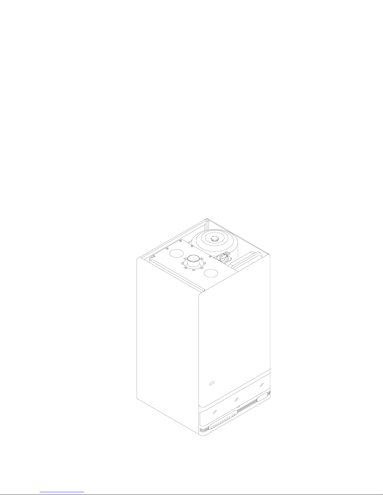
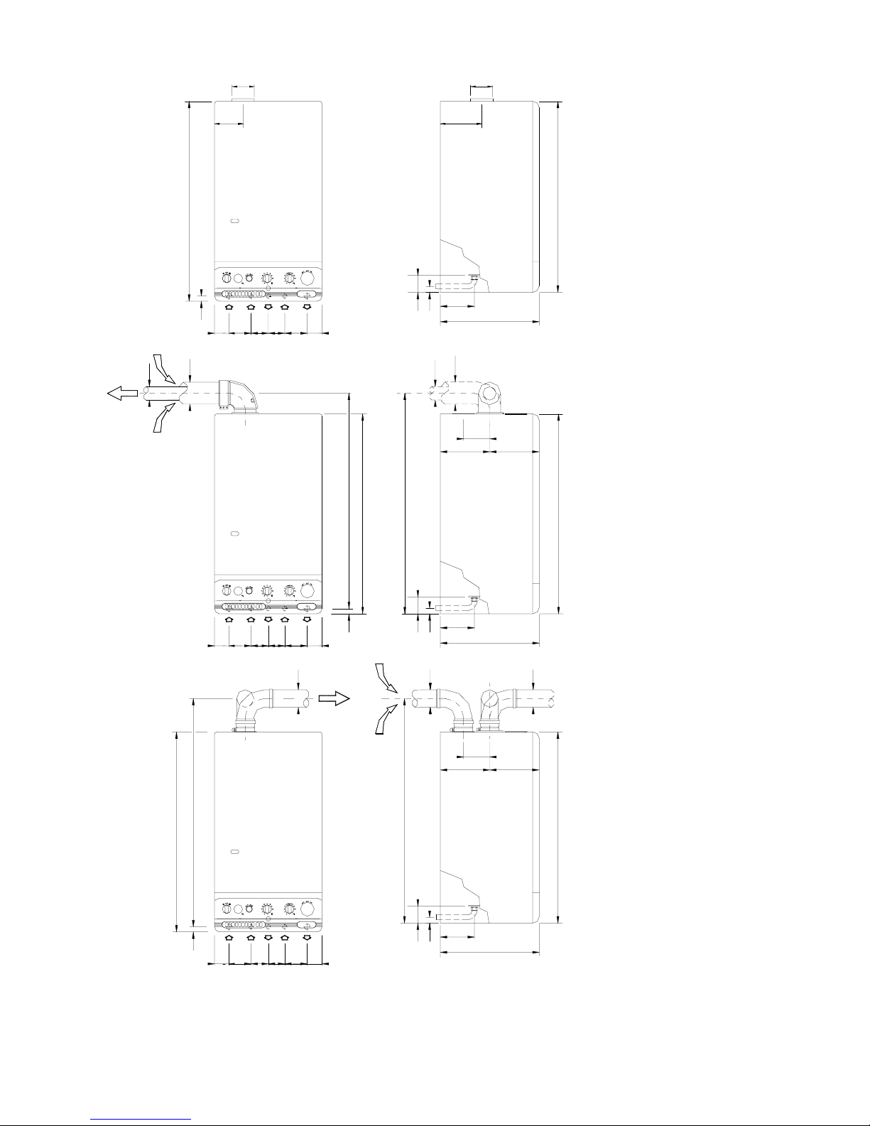
TYPE B WALL-MOUNTED
BOILERS
OPEN COMBUSTION CIRCUIT:
TYPE C WALL-MOUNTED
BOILERS
SEALEDCOMBUSTION CIRCUIT:
Kit A
Horizontal coaxial exhaust flue
system with 360° rotation.
It allows the flue exhaust and the
air intake directly to an external
wall. .
To insert a bend, reduce total flue
length by 0.8 m.
Kit B
Double exhaust/emission twin
flue system with 360° rotation.
It allows the flue exhaust into a
flue duct and the air intake directly
from an external wall.
To insert a bend, reduce total flue
length by 1.5 m.
R RETURN ¾”
G GAS ½”
C HOT WATER ½”
F COLD WATER ½”
A HEATING FLOW ¾”
ATTENTION: USE APPROVED TYPE FLUE TERMINALS ONLY WITH THE FLUE KIT.
130
900
450
130
56
155
26
6873F102
A
140
900
78101G68
R
26
C
235
900
101
G
900
78
26
101R68
G AFC
73 102 68
1003
80
68
R
56
155
26
450
=
1029
120
=
80
56
C78F73A
102 68
26 950
900
976
155
26
450
120
=
60
100
=
900
100
60
80
Installation Manual
Wall Hung Boiler with D.H.W. Storage Cylinder Low Nox – Cod. 99881NA – July 2001
5
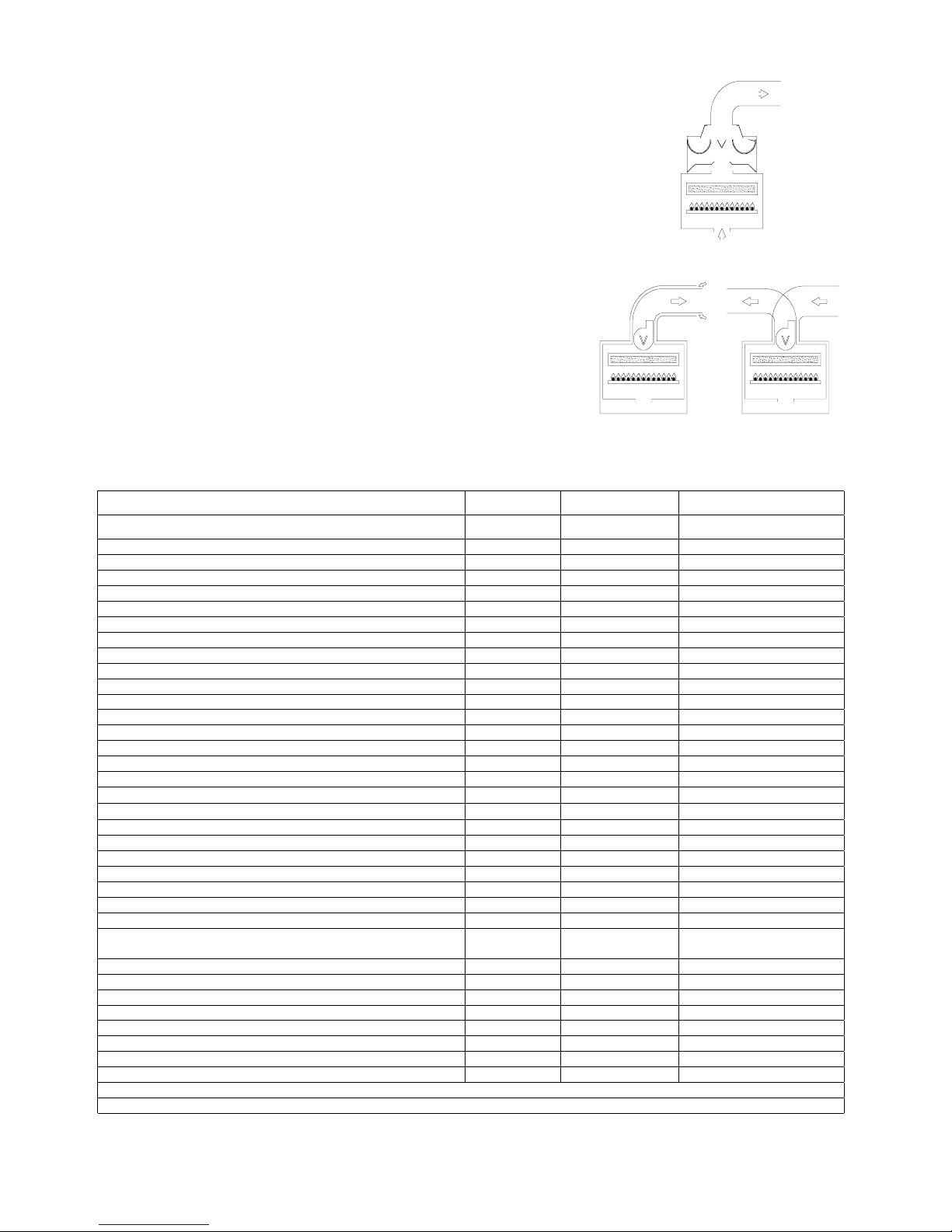
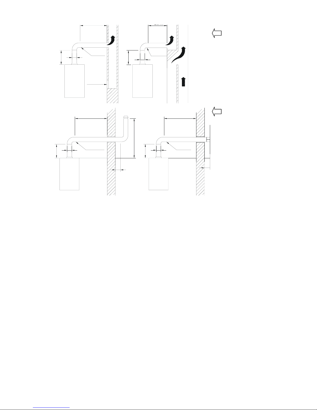
FLUE EXHAUST DIRECTLY
INTO A DUCT (CHIMNEY)
OR COLLECTIVE BRANCH-
TYPE FLUE
VERTICAL EXHAUST
Open chamber model
A maximum of 3 changes of
direction are allowed.
Keep to the distances and
angles shown in the diagram.
FLUE EXHAUST DIRECTLY
TO OUTSIDE
VERTICAL EXHAUST
Open chamber model
A maximum of 2 changes of
direction are allowed including
the first connection to the
boiler.
Keep to the distances and
angles shown in the diagram
For the flue exhaust from multiple superimposed type "B" gas boilers with natural draught into newly installed collective flues
(CCR) with natural draught, follow the directions set out in the UNI 10640 standard.
It should be noted that these type of flues do not apply in the case of boilers equipped with mechanical means of flue exhaust.
For the FLUE EXHAUST from multiple combined type "C" room sealed gas boilers equipped with exhaust fans into singlechimney collective flues with natural draft or multiple combined flues, follow the directions set out in the UNI 10640 standard.
CONNECTION OF FLUE PIPES
All boilers must be connected to a duct for discharging the burnt gasses; the section of this duct must not be less than the
diameter of the pipe coming out of the boiler and must be sealed airtight so that no burnt gasses can leak out. There must be no
long horizontal sections or abrupt deviations along its length (see fig. 1-2).
• For type B open combustion circuit boilers;
• connect the boiler to the chimney using a ∅ 130 link.
• For type C12 sealed combustion circuit boilers;
• KIT A - COAXIAL EXHAUST connect using the ∅ 100 - 60 double elbow and 2 coaxial pipes; ∅ 60 for EXHAUST of
combustion gasses - ∅ 100 for air INTAKE.
• For type C32 sealed combustion circuit boilers;
• KIT B – TWIN PIPE SYSTEM connect using 2 sections with a ∅ 80 elbow for the EXHAUST of combustion gasses - ∅ 80
for air INTAKE.
N.B.: FLUE KITS are supplied in a separate box.
Fig. 1
Fig. 2
3% minimum
slope
Suction
opening
2.5 m max.
2d
d
3% minimum
slope
2d
d
2.5 m.
max.
1.5 m min.
1 m min.
d
min.
1 m min.
d
3% minimum
slope
2d
2d
2d
3% minimum
slope
 Loading...