

Page 1
CE
0694
ENGLISH
Technical Specification RADIANT BRUCIATORI S.p.A. Montelabbate (PU) ITALY By Technical Department
INSTALLATION, USE,
AND MAINTENANCE MANUAL
FOR GAS FIRED, WALL-HUNG BOILERS
WITH DOMESTIC HOT WATER
STORAGE CYLINDER
Model
RMA
TYPE B OPEN COMBUSTION CHAMBER
Model
RMAS
TYPE C ROOM SEALED
Page 2

Page 3

INDEX
USER MANUAL page I-II
INSTALLATION INSTRUCTIONS AND WARNINGS page 2
INSTALLATION REQUIREMENTS page 3
OVERALL DIMENSIONS - EXHAUST FLUE SYSTEM page 4
GENERAL INSTALLATION REQUIREMENTS page 6
BOILER INSTALLATION page 8
ELECTRICAL CONNECTIONS page 10;19-22
BOILER CONTROL PANEL page 11
STARTING UP THE BOILER FOR THE FIRST TIME page 11
BOILER ADJUSTMENTS page 13
MULTIGAS OPERATION page 14
REGULATING THE GAS PRESSURE page 15
TECHNICAL DATA page 16
MAINTENANCE page 24
UNPACKING page 24
FAULT FINDING CHART page 25
SHORT LIST OF COMPONENTS page 26
Page 4
User Manual
Wall Hung Boiler with D.H.W. Storage Cylinder Low Nox – Cod. 99881NA – July 2001
I
BOILER OPERATION AND ADJUSTMENT PROCEDURES FOR USER
Before turning on the boiler read the following warnings carefully .
Make sure that the warranty booklet carries the stamp of the authorised technician responsible for installing the boiler.
Installation, starting up for the first time, adjustments and maintenance operations must all be carried out solely by qualified
technicians. Incorrect installation may cause damage to persons, animals or property for which the manufacturer cannot be held
liable.
WARNING!
⇒ Do not start the boiler unless you are sure it has been thoroughly tested by an authorised technician.
⇒ Check that the regulations regarding air intakes and ventilation of the room where the boiler is installed have been
fully complied with (see installation instructions pag.2).
⇒ The anti-freeze system will come into operation only if the boiler is in the winter (!!!!) or summer ("""") position (with
selector switch 1 in fig. 1 turned to the summer or winter position) and the gas supply turned on. The manufacturer
can accept no responsibility for damage to the boiler caused by lack of observation of these requirements.
⇒ If the boiler should freeze up, under no circumstances attempt to turn it on but call the service centre immediately.
LEGEND
(see fig. 1)
1.
SUMMER-WINTER ON-OFF SWITCH
2.
LOCK-OUT INDICATOR
3.
HEATING TEMPERATURE ADJUSTMENT KNOB
4.
WATER TEMPERATURE ADJUSTMENT KNOB
5.
SPACE FOR ADDING AN OPTIONAL TIMER
SELF- DIAGNOSTIC LEGEND
(see fig. 2)
6.
OPERATING/ POWER INDICATOR
7.
DOMESTIC HOT WATER OPERATION
8.
HEATING OPERATION
9.
FLASHING LIGHT DENOTING AIR PRESSURE
SWITCH FAILURE
10.
FLASHING LIGHT DENOTING DOMESTIC WATER
SENSOR FAILURE
11.
FLASHING LIGHT DENOTING HEATING SENSOR
FAILURE
12.
FLASHING LIGHT DENOTING 90° C MAX
TEMPERATURE SENSOR FAILURE
13.
FLASHING LIGHT DENOTING FLUE SAFETY THERMOSTAT FAILURE
14.
FLASHING LIGHT DENOTING LACK OF WATER IN
SYSTEM
15.
WATER PRESSURE LEVEL 1 BAR
16.
WATER PRESSURE LEVEL 1.5 BAR
17.
ELECTRONIC TEMPERATURE INDICATOR
Turning on the electronic ignition:
# turn on the gas cock situated under the boiler grill;
# turn selector switch 1 to the ! symbol denoting winter (see
fig.2);
#
make sure that 6 light is ON (see fig. 2) and the no.15 or
no.16 lights are ON (see fig. 2); if light no.14 flashes, it
means water deficiency in the system: open the filling tap
located ander the boiler (see fig. 3) and fill the system until
a pressure of 1.5 bar has been reached (light no.16 ON; see fig. 2) and then close the filling tap.
# The automatic ignition system will turn the burner on.
It may be necessary to repeat the procedure a few times to purge air from the pipes. To repeat the ignition procedure press
release button 2 (see fig.1) and then try the ignition procedure once again. If the boiler does not start, press the reset button 2
(see fig. 1). IMPORTANT
should the boiler fail to ignite wait 3 minutes before pressing button again.
If locking-out persists, turn boiler OFF and call an authorised radiant service engineer.
Fig. 3
6
7
1
17
1089
11 12
13
14
15 16
23 4
5
5030 40 60 70 80
1
1.5
PRESSURE GAUGE
ELECTRONIC WATER
SELF DIAGNOSTIC
Fig. 1
Fig. 2
Page 5

User Manual
Wall Hung Boiler with D.H.W. Storage Cylinder Low Nox – Cod. 99881NA – July 2001
II
Turning on procedure for electronic ignition (only for U.k. and Ireland):
# turn on the gas cock situated under the boiler grill;
# turn selector switch 1 to the ! symbol denoting winter (see fig.2);
# make sure that 6 light is ON (see fig. 2 pag. I) and the no.15 or no.16 lights are ON (see fig. 2 pag. I); if light no.14 flashes, it
means water deficiency in the system: open the tap on the filling loop and fill the system until a pressure of 1.5 bar has been
reached (light no.16 ON; see fig. 2 pag. I) and then close the tap.
# The automatic ignition system will turn the burner on.
It may be necessary to repeat the procedure a few times to purge air from the pipes. To repeat the ignition procedure press
release button 2 (see fig. 1 pag. I) and then try the ignition procedure once again. If the boiler does not start, press the reset
button (see fig. 1 pag. I). IMPORTANT
should the boiler fail to ignite wait 3 minutes before pressing button again.
If locking-out persists, turn boiler OFF and call an authorised service engineer.
Turning off boilers with electronic ignition :
# turn selector switch 1 to the OFF position;;
# if the boiler will not be used for long periods it is recommended that the gas cock under the boiler grill be shut off.
THE BOILER IN USE
Summer-winter use (see fig. 1 pag. I).
# turn the selector switch 1 to the ! program to operate the boiler in the WINTER position for both heating and hot water;
# turn the selector switch 1 to the " program to operate the boiler in the SUMMER position for just hot water;
# if the system has a room thermostat, set this to the temperature required (the law states 20°C).
REGULATING THE HEATING TEMPERATURE
The heating temperature is regulated by turning knob 3 (see fig. 1 pag. I).
# turn it counter-clockwise to lower the temperature.
# turn it clockwise to raise the temperature.
# the temperature range can be adjusted from a minimum of 30°C to a maximum of 80°C.
REGULATING THE HOT WATER TEMPERATURE
The hot water temperature is regulated by turning knob 4 (see fig. 1 pag. I).
# turn it counter-clockwise to lower the temperature
# turn it clockwise to raise the temperature
# the temperature range can be adjusted from a minimum of 35°C to a maximum of 60°C.
WARNINGS FOR THE USER
To keep the boiler in efficient and safe operating condition, carefully follow the instructions listed below:
# Have normal maintenance performed at least once a year by one of our authorised service centres (a fee will be charged),
combustion tests are necessary every two years and should again be carried out by a qualified Radiant technician (in
accordance with D.P.R. 412 regulations, 26-08-93).
# Periodically check system pressure on the pressure gauge and check that pressure is between 0.5 - 1.5 bar with the system
cold.
# Do not clean the casing or internal parts of the boiler with reducing agents or solvents. Clean only with soap and water.
# Never leave flammable materials in the immediate vicinity of the boiler.
# For greater comfort and more rational use of heat, it is advisable to install a room thermostat connected to a clock timer to
turn the boiler on and off during the course of the day or week (in accordance with D.P.R. 412 regulations, 26-08-93).
# The boiler is equipped with an anti-freeze system, which is operative with switch 1 in either SUMMER " or WINTER !
position, even if the room thermostat is set at zero, as long as there is electrical power and gas feed.
FLUE SAFETY
Natural draft boilers are equipped with a device that controls correct evacuation of exhaust fumes. This device guarantees
maximum safety during operation. If the flue is partially or completely obstructed, or if its section is insufficient for evacuation of
exhaust fumes, the device will intervene and block the flow of gas to the main burner and to the pilot light, turning off the boiler.
If this occurs, contact an authorised technician , close the gas tap and turn electrical mains off.
Do not tamper with the device in any way.
Page 6
Installation Manual
Wall Hung Boiler with D.H.W. Storage Cylinder Low Nox – Cod. 99881NA – July 2001
1
THE FRIENDLY POWER OF HEAT
Thank you for choosing RADIANT
Declaration for purposes of Art. 7 of Law 46 of 5 April 1990.
RADIANT BRUCIATORI S.p.A. hereby declares that all of its products are constructed to industry standards as required by the
Article in question and by Article 5 of the law in effect (D.P.R. no. 447/91).
RADIANT BRUCIATORI S.p.A. products are type tested EC.
All RADIANT boilers are constructed according to UNI - CIG (EC) norms. The materials used, such as copper, brass, and
stainless steel, form a compact, homogeneous, highly functional unit that is easy to install and simple to operate. The wallmounted boiler is equipped with all of the approved accessories required to make it a true, independent heating plant for home
heating and for the production of hot water for domestic needs. All boilers are fully inspected, and come with a certificate of
quality signed by the inspector and with a warranty certificate. This booklet must be read carefully and stored in a safe place
near the boiler.
RADIANT BRUCIATORI S.p.A. declines any and all responsibility for misinterpretations of this booklet deriving from
any translations of same.
RADIANT BRUCIATORI S.p.A. will not be responsible for non-observance of the instructions contained in this booklet
or for the consequences of any action not specifically described herein.
Page 7

Installation Manual
Wall Hung Boiler with D.H.W. Storage Cylinder Low Nox – Cod. 99881NA – July 2001
2
INSTALLATION INSTRUCTIONS
WARNINGS
THIS INSTALLATION, USE, AND MAINTENANCE MANUAL IS AN ESSENTIAL AND INTEGRAL PART OF THE PRODUCT, AND MUST ALWAYS BE KEPT NEAR THE
DEVICE.
THE WARNINGS CONTAINED IN THIS SECTION ARE ADDRESSED BOTH TO THE USER AND TO INSTALLATION AND MAINTENANCE PERSONNEL.
THE USER WILL FIND INFORMATION ON OPERATION AND LIMITS OF USE IN THE ACCOMPANYING MANUAL, WHICH SHOULD BE READ VERY CAREFULLY.
STORE THE MANUAL CAREFULLY FOR FUTURE REFERENCE.
1) GENERAL WARNINGS
Installation must be performed in observance of current norms, according to the constructor’s instructions, and by professionally qualified personnel.
Professionally qualified personnel are those having technical competence in the sector of application of the device (civil or industrial), and, in particular, the constructor’s
authorised service centres.
Incorrect installation may cause damage to persons, animals, or property, for which the constructor assumes no liability.
• After completely removing the packing, make sure that the contents are in perfect condition.
• In case of doubt, do not use the equipment. Consult the supplier.
• Packing materials (cardboard carton, wooden crate, nails, clips, plastic bags, polystyrene, etc.) are potentially dangerous and must be kept away from children.
• Before performing any cleaning or maintenance operation, turn off the unit by means of the mains switch and/or by means of the appropriate cut-off devices.
• Do not block the air intake or heat dissipation grates.
• In the event of breakdown and/or poor functioning of the device, turn it off and do not attempt to repair it or take any direct action. Refer to professionally qualified personnel
only.
• Any repairs must be performed exclusively by a service centre authorised by the constructor, and with original spare parts only.
• Non-observance of the above instruction may compromise the safety of the device. To guarantee efficient and correct operation, the device should undergo period
maintenance by professionally qualified personnel according to the constructor’s instructions.
• Whenever the device is to be put out of service, secure all potentially hazardous parts to prevent accidents or damage.
• If the device is sold or transferred to another owner, or if you move and leave the boiler, make sure that this booklet stays with the boiler so that it may be consulted by the
new owner and/or by the installer.
• Use only original spare parts for all devices with optionals or kits (including electrical ones).
WARNING: this device must be used for its intended purpose, i.e., heating and production of domestic hot water. Any other use is improper and therefore dangerous. The
constructor will have no contractual or extracontractual liability for damage caused by incorrect installation and/or use or by non-observance of instructions supplied by the
constructor.
This device must be used exclusively with a sealed central heating system equipped with an expansion vessel.
2) WARNINGS REGARDING INSTALLATION
Warranty expires 12 months from date of installation and in all cases no later than 18 months from date of construction. First start-up must be performed by authorised
personnel only. For any operation on the hydraulic, gas, or electrical circuit regarding the heating unit, refer to authorised technicians only and use original spare parts only.
Wall-mounted boilers are not to be installed in damp rooms, and must be protected against sprays or jets of water or other liquids to prevent malfunctions of the electrical and
heating devices. They must not be exposed to direct steam from cookers, and nothing must be placed on top of them. This heating unit has been constructed to heat the home
and to produce hot water. The constructor declines all responsibility for incorrect installation and/or use of the device. Do not leave the device on when it is not being used:
close the gas cock and turn off the mains switch. If you smell gas in the room in which the device is installed, do not operate any electrical switches, telephones, or any other
device that might cause a spark. Immediately open doors and windows to create an air current to clear the room. Close the main gas cock (at the meter) or the cylinder cock,
and request immediate technical service.
Do not tamper with the device.
SYSTEMS WITH THERMOSTATS
A by-pass must be installed in heating systems with radiators thermostats.
As required by current norms, these devices must be installed by qualified personnel only, who must respect norms UNI-CIG 7129 and 7131 and revisions, fire department
regulations, and requirements of the local gas company. Before installing the boiler, make sure that the water and heating systems are compatible with its output. The room
must be properly ventilated by means of an air intake (see UNI 7129/92 and UNI 7129/95 FA).
The air intake must be at floor level open flue only, at a point where it cannot be obstructed, and protected by a grate that does not reduce the useful section of flow.
The use of air flows from adjacent rooms is permitted as long as such rooms are in depression with respect to the outside and as long as there are no wood-burning fireplaces
or fans installed there. If the boiler is to be installed externally (for example, on balconies or terraces), make sure that it is protected against atmospheric agents to prevent
damage to components and voiding of the warranty. In such cases we recommend building a heat compartment to protect the boiler against inclement weather.
Check the technical data on the packing and on the plate located inside the front casing. Check that the burner is suitable for use with the type of gas available.
Make sure that all pipes and connections are perfectly sealed and that there are no gas leaks.
We recommend that the pipes be cleaned out to remove any residues that might negatively affect the operation of the boiler.
3) GENERAL WARNINGS BASED ON TYPE OF POWER SUPPLY
POWER SUPPLY
Electrical safety is achieved only when the device is correctly and efficiently earthed as per current safety norms (IEC 64-8 Electrical Part).
• This fundamental safety requirement must be checked. In case of doubt, request a check of the electrical system by professionally qualified personnel. The constructor will
not be liable for any damage caused by lack of or improper earthing of the system.
• Have professionally qualified personnel check that the electrical system is adequate for the maximum absorbed power of the device (indicated on the plate). In particular,
make sure that the section of the system wires is suitable for the maximum absorbed power of the device.
• Do not use adapters, multiple sockets, and/or extension cords to power the device from the electrical mains.
• Provide a unipolar switch as required by current safety regulations to connect the device to the mains.
• The use of any electrical device requires the observance of some fundamental rules, such as:
• do not touch the device with wet or damp parts of the body and/or with bare feet
• do not pull on electrical cables
• do not expose the device to atmospheric agents (rain, sun, etc.) unless specifically provided for
• do not allow the device to be used by children or anyone unfamiliar with its operation
• The power cable must not be replaced by the user.
• If the cable becomes damaged, turn off the device and have the cable replaced by professionally qualified personnel only.
• If you decide not to use the device for an extended length of time, turn off the mains switch that feeds all components of the system using electrical energy (pumps, burner,
etc.).
Page 8
Installation Manual
Wall Hung Boiler with D.H.W. Storage Cylinder Low Nox – Cod. 99881NA – July 2001
3
TECHNICAL DATA
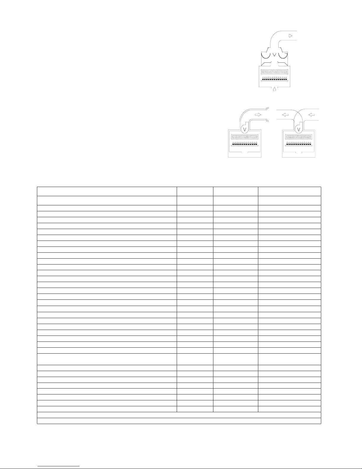
Type B unit
Type B boilers have open combustion chambers, and must be connected to a
flue duct to convey combustion exhaust out of the room. Air for combustion is
taken directly from the room in which the boilers are installed.
Type C unit
Type C devices are devices in which the combustion circuit (air intake,
combustion chamber, exchanger, combustion exhaust) is sealed off from the
place where they are installed.
CENTRAL HEATING - DOMESTIC HOT WATER
open combustion circuit type
RMA 21 E
- electronic ignition
CENTRAL HEATING - DOMESTIC HOT WATER
sealed combustion circuit type
RMAS 21 E
- electronic ignition
Technical data
MODELLI RMA 24 E RMAS 24 E
Maximum rated input KCal/h 25628 25628
Kw 29.8 29.8
BTU/h 101692 101692
Minimum rated input KCal/h 15000 15000
Kw 17.5 17.5
BTU/h 59250 59250
Maximum rated output KCal/h 22950 23090
Kw 26.68 26.85
BTU/h 91066 91621
Minimum rated output KCal/h 12950 12900
Kw 15.06 15
BTU/h 51386 51187
Heting temperature adjustment °C 30-80 30-80
Max. working pressure (heating) bar 3 3
Min. working pressure (heating) bar 0.3 0.3
Expansion vessel capacity (initial pressure 1 bar) Litres 10 10
Hot stored water max. temperature °C 60 60
Continuous hot water drawing with ∆t 30°
Litres/h 790 790
Maximum continuous mixed drawing with ∆t 30°, first 10 minutes
Litres 150 150
Time to heat water in storage tank from 10°C to 60°C min. 5 5
Max. working pressure (water) bar 6 6
Min. working pressure (water) bar 0.5 0.5
Width mm. 490 490
Height mm. 900 900
Depth mm. 450 450
Weight Kg. 60 65
Flue diameter Ø 130
100/60
80/80
Flow/return connections 3/4” - 3/4” 3/4” - 3/4”
Cold water connections Ø 1/2” 1/2”
Hot water connections Ø 1/2” 1/2”
Gas connections Ø 1/2” 1/2”
Electrical connection 50 Hz V 230 230
Power supply W 170 170
Burner jets NP 24 G20 Ø 1.25 1.25
Burner jets NP 24 G30 Ø 0.77 0.77
Gas category: IT II2H3 Gas supply pressure: G20 20 mbar / G30/31 29-30/37 mbar
FORCED CIRCULATION
C32
C12
C52
B11
Coaxial ver tical
Coaxial hor izontal
Double
Page 9
Installation Manual
Wall Hung Boiler with D.H.W. Storage Cylinder Low Nox – Cod. 99881NA – July 2001
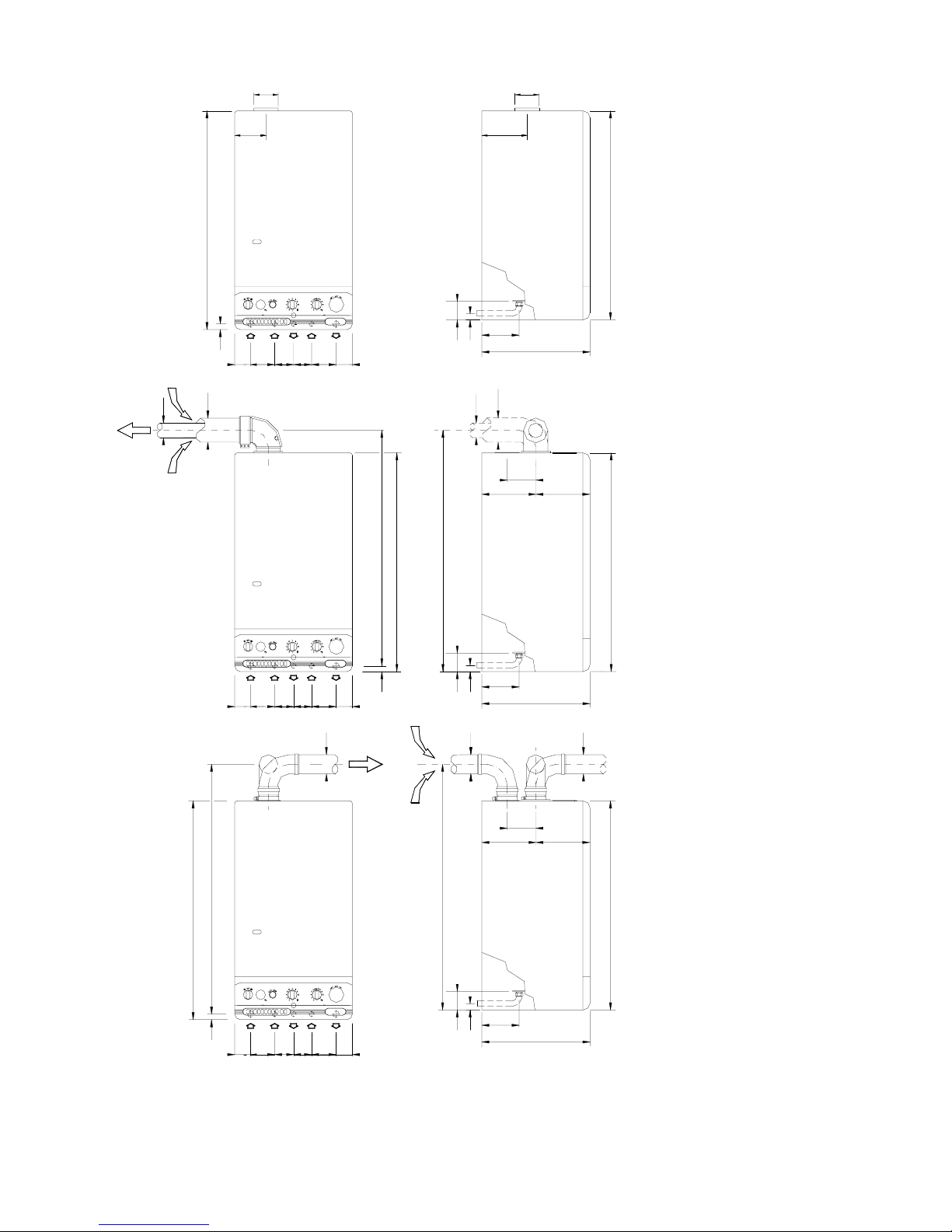
4
TYPE B WALL-MOUNTED
BOILERS
OPEN COMBUSTION CIRCUIT:
TYPE C WALL-MOUNTED
BOILERS
SEALEDCOMBUSTION CIRCUIT:
Kit A
Horizontal coaxial exhaust flue
system with 360° rotation.
It allows the flue exhaust and the
air intake directly to an external
wall. .
To insert a bend, reduce total flue
length by 0.8 m.
Kit B
Double exhaust/emission twin
flue system with 360° rotation.
It allows the flue exhaust into a
flue duct and the air intake directly
from an external wall.
To insert a bend, reduce total flue
length by 1.5 m.
R RETURN ¾”
G GAS ½”
C HOT WATER ½”
F COLD WATER ½”
A HEATING FLOW ¾”
ATTENTION: USE APPROVED TYPE FLUE TERMINALS ONLY WITH THE FLUE KIT.
130
900
450
130
56
155
26
6873F102
A
140
900
78101G68
R
26
C
235
900
101
G
900
78
26
101R68
G AFC
73 102 68
1003
80
68
R
56
155
26
450
=
1029
120
=
80
56
C78F73A
102 68
26 950
900
976
155
26
450
120
=
60
100
=
900
100
60
80
Page 10
Installation Manual
Wall Hung Boiler with D.H.W. Storage Cylinder Low Nox – Cod. 99881NA – July 2001
5
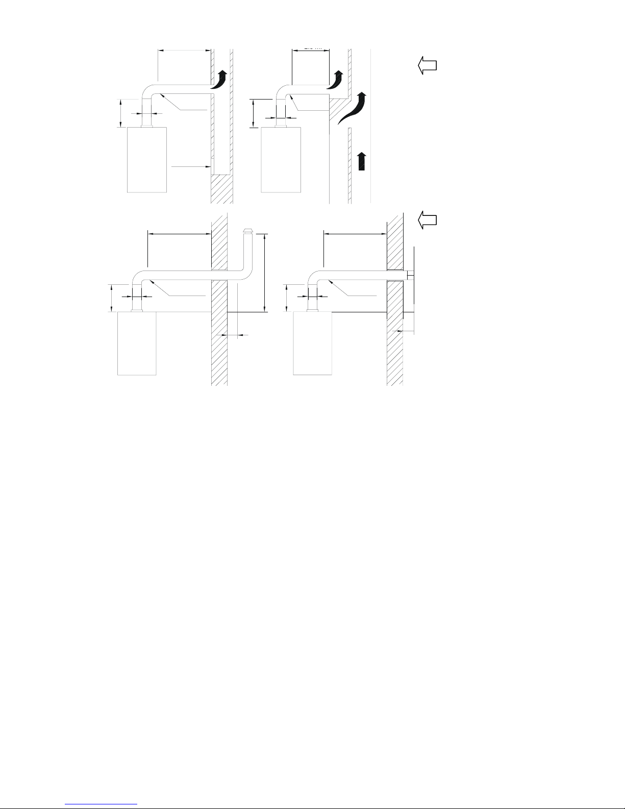
FLUE EXHAUST DIRECTLY
INTO A DUCT (CHIMNEY)
OR COLLECTIVE BRANCH-
TYPE FLUE
VERTICAL EXHAUST
Open chamber model
A maximum of 3 changes of
direction are allowed.
Keep to the distances and
angles shown in the diagram.
FLUE EXHAUST DIRECTLY
TO OUTSIDE
VERTICAL EXHAUST
Open chamber model
A maximum of 2 changes of
direction are allowed including
the first connection to the
boiler.
Keep to the distances and
angles shown in the diagram
For the flue exhaust from multiple superimposed type "B" gas boilers with natural draught into newly installed collective flues
(CCR) with natural draught, follow the directions set out in the UNI 10640 standard.
It should be noted that these type of flues do not apply in the case of boilers equipped with mechanical means of flue exhaust.
For the FLUE EXHAUST from multiple combined type "C" room sealed gas boilers equipped with exhaust fans into singlechimney collective flues with natural draft or multiple combined flues, follow the directions set out in the UNI 10640 standard.
CONNECTION OF FLUE PIPES
All boilers must be connected to a duct for discharging the burnt gasses; the section of this duct must not be less than the
diameter of the pipe coming out of the boiler and must be sealed airtight so that no burnt gasses can leak out. There must be no
long horizontal sections or abrupt deviations along its length (see fig. 1-2).
• For type B open combustion circuit boilers;
• connect the boiler to the chimney using a ∅ 130 link.
• For type C12 sealed combustion circuit boilers;
• KIT A - COAXIAL EXHAUST connect using the ∅ 100 - 60 double elbow and 2 coaxial pipes; ∅ 60 for EXHAUST of
combustion gasses - ∅ 100 for air INTAKE.
• For type C32 sealed combustion circuit boilers;
• KIT B – TWIN PIPE SYSTEM connect using 2 sections with a ∅ 80 elbow for the EXHAUST of combustion gasses - ∅ 80
for air INTAKE.
N.B.: FLUE KITS are supplied in a separate box.
Fig. 1
Fig. 2
3% minimum
slope
Suction
opening
2.5 m max.
2d
d
3% minimum
slope
2d
d
2.5 m.
max.
1.5 m min.
1 m min.
d
min.
1 m min.
d
3% minimum
slope
2d
2d
2d
3% minimum
slope
Page 11

Installation Manual
Wall Hung Boiler with D.H.W. Storage Cylinder Low Nox – Cod. 99881NA – July 2001
6
GENERAL INSTALLATION REQUIREMENTS
GAS SAFETY
It is the law that all gas appliances are installed by a CORGI registered installer in accordance with the regulations listed below.
Failure to install appliances correctly could lead to prosecution. It is in your own interest and that of safety to ensure that the
law is complied with. Failure to have your appliance installed to comply with the installation instructions and the requirements
listed below could invalidate your guarantee.
RELATED DOCUMENTS
The installation of the boiler must be in accordance with the relevant requirements of the Gas Safety regulations, Building
regulations, I.E.E. regulations and the byelaws of the local water authority.
It should be in accordance also with any relevant requirements of the local authority and the relevant recommendations of the
following British Standard Codes of Practice:
B.S 6400: 1985 & B.S. 6891 : 1988.
BS 5376: Selection and Installation of Gas Space Heating ( 1 and 2 family gases)
Part 2: Boilers of rated input not exceeding 60 Kw
BS 5449: Central Heating for domestic premises
Part 1: Forced circulation Hot Water System
CP 342: Centralised Hot Water Supply BS 6700 : 1987
Part 2: Buildings other than individual
BS 5440: Flues and air supply for Gas Appliances of rated input not exceeding
60 Kw (1 and 2 family gases)
Part 1: Flues
Part 2: Air Supply
BS 5446: 1990: Installation of Gas Hot Water supplies for domestic purposes
GAS SUPPLY
Service Pipes: The local gas region should be consulted at the installation planning stage in order to establish the availability of
supply of gas. An existing service pipe must not be used without prior consultation with the local gas region.
Meters: A gas meter is connected to the service pipe by the local gas region or local gas region contractor. An existing meter
should be checked to ensure that it is capable of passing an additional 3.4 m3/hr (125 ft/hr) before the appliance is installed.
The meter outlet governor should ensure a nominal dynamic pressure of 20m Bar, (8 in wg) at the boiler. Installation pipes
should be fitted in accordance with BS6891.1988. Pipework from the meter to the boiler must be 22mm copper tube. The
complete installation must be tested for soundness as described in the above code, BS 6400: 1985 & BS6891.
IMPORTANT: BOTH THE USER AND THE MANUFACTURER RELY UPON THE INSTALLER, WHOSE JOB IS TO INSTALL
THE BOILER AND CONNECT IT TO A CORRECTLY DESIGNED HEATING SYSTEM. THE INSTALLER SHOULD
ACQUAINT HIMSELF WITH THE CONTENTS OF THIS PUBLICATION AND THE RELEVANT BRITISH STANDARDS
CONCERNING INSTALLATION REQUIREMENTS.
LOCATION OF BOILER
In siting the combination boiler, the following limitations MUST be observed:
The position selected for installation should be within the building, and MUST allow
adequate space for installation, servicing and operation of the combination boiler, and for air circulation around it. The boiler is
not suitable for external installation.
This position MUST also allow for a suitable flue termination to be made. The boiler must be installed on a flat vertical wall
which is capable of supporting the weight of the combination boiler, and any ancillary equipment.
If the boiler is to be fitted in a timber framed building it should be fitted in accordance with the British Gas publication "Guide for
Gas Installations in Timber Frame Housing, Reference DM2". If in doubt, advice must be sought from the local region of British
Gas.
The boiler may be installed in any room or internal space, although particular attention is drawn to the requirements of the
current I.E.E. Wiring Regulations, and in Scotland the electrical provisions of the Building Regulations applicable in Scotland,
with respect to the installation of the boiler in a room or internal space containing a bath or shower.
Where a room-sealed appliance is installed in a room containing a bath or shower, any electrical switch or appliance control
utilising mains electricity must be so situated that it cannot be touched by a person using the bath or shower.
A compartment used to enclose the combination boiler MUST be designed and constructed specifically for this purpose. An
existing cupboard, or compartment, may be used provided it is modified accordingly.
Page 12

Installation Manual
Wall Hung Boiler with D.H.W. Storage Cylinder Low Nox – Cod. 99881NA – July 2001
7
Where installation will be in an unusual location, special procedures may be necessary. BS 6798 gives detailed guidance on
this aspect.
For clearances to be made available for installation and servicing, see Sections 5.2.2. to 5.2.4.
FLUE POSITION
IMPORTANT: THE FLUE SYSTEM SHALL BE INSTALLED IN ACCORDANCE WITH THE RECOMMENDATIONS
CONTAINED IN BS 5440:1.
The boiler MUST be installed so that the terminal is exposed to the external air.
It is important that the position of the terminal allows free passage of air across it at all times.
If the terminal discharges into a pathway or passageway check that combustion products will not cause nuisance and that the
terminal will not obstruct the passageway.
In certain weather conditions a terminal may emit a plume of steam. Positions where this would cause a nuisance should be
avoided.
IMPORTANT REQUIREMENT: The correct dimensional relationship between the terminal and any obstruction, openable
window or ventilator as shown in Fig 1 pag.7 It is ESSENTIAL TO ENSURE, in practice, that products of combustion
discharging from the terminal cannot re-enter the building, or any other adjacent building, through ventilators, windows, doors,
other sources of natural air infiltration, or forced ventilation/air conditioning systems. If this should occur, the appliance MUST
BE TURNED OFF IMMEDIATELY and the local gas region consulted.
Where the lowest part of the terminal is fitted less than 2m (6.6ft) above a balcony, above ground, or above a flat roof to which
people have access, the terminal MUST be protected by a purpose designed guard.
Where the terminal is fitted within 850mm (34in) of a plastic or painted gutter, or 450mm (18in) of painted eaves, an aluminium
shield of at least 1500mm (59in) long should be fitted to the underside of the gutter painted surface.
The air inlet/products outlet duct and the terminal of the boiler MUST NOT be closer than 25mm (1in) to combustible material.
TERMINAL POSITION
A Directly below an openable window, air vent 300 mm (12in)
or any other ventilation opening
B Below guttering, drain pipes or soil pipes 75 mm (3in)
C/D Below eaves, balconies or carport roof 200 mm (8in)
E From vertical drain pipes or soil pipes 75 mm (3in)
F From internal or external corners 300 mm (12in)
G Above adjacent ground, roof or balcony level 300 mm (12in)
H From a surface facing the terminal 600 mm (24in)
I From a terminal facing the terminal 1200 mm (48in)
J From an opening in the carport (eg door, window) 1200 mm (48in)
into the dwelling
K Vertically from a terminal on the same wall 1500 mm (60in)
L Horizontally from a terminal on the same wall 300 mm (12in)
M Adjacent to opening 300 mm
Under carport with open sides
Fig. 1
Page 13

Installation Manual
Wall Hung Boiler with D.H.W. Storage Cylinder Low Nox – Cod. 99881NA – July 2001
8
MINIMUM DISTANCES FOR FIXING TO WALL
To allow access in the boiler for maintenance operations, the minimum
distances shown below must be respected (fig. 1):
To facilitate installation, the boiler is supplied with a template for
advance location of connections to pipes. In this way, you may simply
hook up the boiler when wall work is completed (fig.2).
Installation Instruction
1) With a spirit level, draw a line on the wall on which the boiler will
be installed (fig. 1).
2) Position the top of the template on the line drawn with the spirit
level (respecting the distances – see fig. 1) than mark the three
points for insertion of the 3 screw anchors or wall anchors for fixing
the boiler hanging bracket. (choose proper anchors according to
the wall type). Next, mark the two points for insertion of the two
screw anchors for fixing the JIG to wall.
3) Fix the hanging bracket and the JIG.
4) Make connections to the hot and cold water supply, to the gas pipe
and to the heating system with the fittings supplied with the boiler
JIG. Connect pipes and valves as shown in the picture
5) Position the boiler paying attention to hang it to the hanging
bracket (do not lean the boiler on the JIG) and make final
connections.
WATER CONNECTIONS
To facilitate installation, the boiler is equipped with a fittings kit (see fig. 3 and 4).
IMPORTANT:
Before connecting the heating system pipes, carefully clean the system to prevent residual dirt from entering into circulation and negatively
affecting boiler function. Install a funnel with discharge under the safety valve (calibrated to 3 bar) to collect water in case of leaking due to
overpressure. No safety valve is needed for the domestic water circuit, but be sure that pressure does not exceed 6 bar.
#
avoid using pipelines of reduced diameter;
#
avoid the use of tight bends and adapters in important sections;
#
clean out the system thoroughly before connecting up the boiler in order to eliminate any residue left in the pipes and radiators.
N.B.:
Make sure that the water and heating pipes are not used as earth connections for electrical apparatus.
R
A
G
C
F
ST
2
1
3 4
400300
450
490
60 60
Fig. 2
R HEATING RETURN ¾”
G GAS ½”
C HOT WATER ½”
F COLD WATER ½”
A HEATING FLOW ¾”
Fig. 1
MINIMUM DISTANCES mm.
R
G
M
F
R
G
F
M
FIXING JIG
W/VALVES
FITTINGS KIT
C
C
Fig. 3
R HEATING RETURN ¾”
G GAS ½”
C HOT WATER ½”
F COLD WATER ½”
A HEATING FLOW ¾”
Fig. 4
Page 14

Installation Manual
Wall Hung Boiler with D.H.W. Storage Cylinder Low Nox – Cod. 99881NA – July 2001
9
GAS CONNECTIONS
The gas supply must be connected up by qualified person.
The following standards must be complied with: UNICIG 7131/72 and UNICIG 7129/92 (of 21/04/93)
Before installing the boiler, make sure of the following:
• the pipeline must be of an adequate section and length to carry the flow required and must be fitted with all safety devices
and measures prescribed by current norms;
• before turning on the boiler make sure the type of gas which it is designed to run on is available
• the gas supply pressure must lie within the values shown on the plate it is recommended that the gas supply pipeline should
be checked for residual obstructions before installing the boiler;
• where the internal gas supply pipe meets the boiler, a gas shutter cock must be fitted which has the same diameter as the
gas inlet pipe;
• check thoroughly that the gas inlets and outlets are properly sealed.
• conversion to allow the boiler to run on LPG to natural gas or vice versa must be carried out by a qualified gas fitter in
accordance with law no.46 of 5th March ‘90 (see p.18).
ANTI-FROST SYSTEM
Radiant boilers are equipped with an Anti-Freeze system which comes into operation when the temperature falls to 5° C
(Heating sensor) and 4° C (Hot water sensor) and protects the boiler down to –2°C external temperature.
To protect the internal Radiators, a room thermostat or remote control must be fitted.
NOTE: The frost system will only come into operation if the boiler is filled with water, and connected to a live gas supply, with
electrical supply and boiler controls in the “ON” position (With the Main switch turned to Summer or Winter position) ) and the
gas supply turned on.
FOR THE INSTALLER
For boilers installed outdoors, where the
temperature may drop below -2° degrees
Centigrade, the system should be filled
with antifreeze liquid by an authorised
technician and a set of electrical heating
elements should be fitted to protect the
domestic hot water heat exchanger.
ADVICE FOR THE SERVICE
TECHNICIAN
If the boiler is out of service
because it is frozen, check that
no parts have been locked in
position by ice before putting it
into operation.
It is advisable to empty the
boiler and the system in case of
no operation for a long period.
Recommended percentage of
glycol for temperatures down to
- 8°C is 20%.The antifreeze
liquid used must be of a good
make and in a solution which
has already been diluted to
avoid the risk of uncontrolled
dilution.
Table n°1
Antifreeze Temperature
Ethylene glycol
(%) volume
freezing point
(°C)
boiling point
(°C)
10 - 4 101
20 -10 102
30 - 17 104
40 - 27 106
50 - 40 109
60 - 47 114
1
2
3
4
5
6
0
1000500 20001500 300
0
02500
Prevalenz a: m.c.a.
Portata: l /h
CIRCULATING PUMP SPECIFICATIONS
Page 15

Installation Manual
Wall Hung Boiler with D.H.W. Storage Cylinder Low Nox – Cod. 99881NA – July 2001
10
ELECTRICAL CONNECTIONS
The boiler works with 230 V 50 Hz AC current and has
maximum input of 170 W. Connection to the electrical
mains must be performed with a device having an
omnipolar opening of at least 3 mm. Make sure the live
and neutral connections conform to the diagram. A secure
earth connection is compulsory.
IMPORTANT
If you need to replace the power supply cable, use cable having
the same characteristics: (HO5 W-F) 3x1 with maximum
external diameter 8 mm.). Connect to the terminal block located
in the instrument panel as follows:
A. Turn off the electrical power supply at the mains.
B. Remove the boiler front casing in the direction of the arrows
(see fig.1).
C. Undo the two side screws on the instrument panel using the
CV screwdriver and pull down the cover (see fig.2 ).
D. Make the following connections:
•
connect the yellow/green wire to the terminal marked with
the earth symbol “
” (see fig.3).
•
connect the blue wire to the terminal marked with the letter
“N”.
•
connect the brown wire to the terminal marked with the
letter “L”.
CONNECTION OF ROOM THERMOSTAT
NOTE: use class II room thermostats only.
The thermostat wire must not be placed in the channel
containing high tension wires, but must have its own line
The room thermostat lead must not exceed 50m n length;
minimum section 0.5 mm.
Connection: after carrying out the operations described
on page 15, proceed as follows:
A. Insert the room thermostat lead into the entry point
on the electrical control box along with all the other
leads on the boiler.
B. Move the bridge PT (see fig.4) from terminal TA to
the free one next to it.
C. Insert the thermostat wires (fig.5) one in terminal TA
and the other in the one next to it occupied by bridge
PT which you have just moved.
If a timer is fitted as well as a room thermostat, carry out
the electrical connections for the timer according to the
indications in figures 6-7.
L
N
OR
TA
TA
OR
TA N
L
4
32
1
5
M
45
1
23
M
N
L
BROWN
YELLOW-GREEN
BLEU
red
yellow
blue
brown
red
yellow
blue
brown
Fig. 1 Fig. 2
Fig. 3
Fig. 4 Fig. 5
Fig. 6
Fig. 7
Page 16

Installation Manual
Wall Hung Boiler with D.H.W. Storage Cylinder Low Nox – Cod. 99881NA – July 2001
11
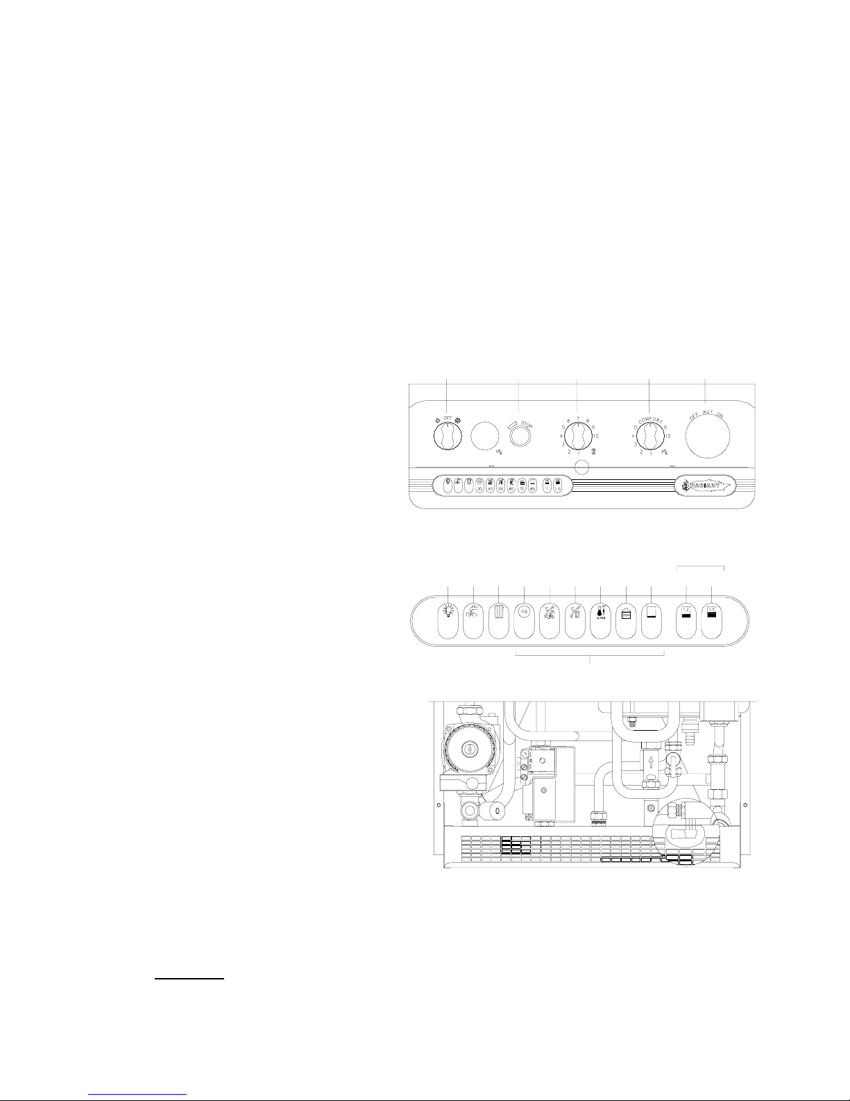
CONTROL PANEL
LEGEND (see fig. 1)
1.
SUMMER-WINTER ON-OFF SWITCH
2.
LOCK-OUT INDICATOR
3.
HEATING TEMPERATURE ADJUSTMENT KNOB
4.
WATER TEMPERATURE ADJUSTMENT KNOB
5.
SPACE FOR ADDING AN OPTIONAL TIMER
SELF- DIAGNOSTIC LEGEND (see fig. 2)
6.
OPERATING/ POWER INDICATOR
7.
DOMESTIC HOT WATER OPERATION
8.
HEATING OPERATION
9.
FLASHING LIGHT DENOTING AIR PRESSURE SWITCH FAILURE
10.
FLASHING LIGHT DENOTING DOMESTIC WATER SENSOR FAILURE
11.
FLASHING LIGHT DENOTING HEATING SENSOR FAILURE
12.
FLASHING LIGHT DENOTING 90° C MAX TEMPERATURE SENSOR
FAILURE
13.
FLASHING LIGHT DENOTING FLUE SAFETY - THERMOSTAT FAILURE
14.
FLASHING LIGHT DENOTING LACK OF WATER IN SYSTEM
15.
WATER PRESSURE LEVEL 1 BAR
16.
WATER PRESSURE LEVEL 1.5 BAR
17.
ELECTRONIC TEMPERATURE INDICATOR
STARTING UP THE BOILER
After connecting up the water supply, before starting up the boiler, carry out the following procedures:
Preliminary procedure
• Do as follows:
• make sure the power supply for the boiler is the same as that stated on the plate (230V - 50Hz) and that the live, neutral and
earth connections have been properly connected;
• make sure the type of gas being supplied is the same as the type for which the boiler has been tested and approved (see
plate data);
• make sure the unit is properly earthed;
• make sure there are no flammable liquids or materials in the immediate vicinity of the boiler;
• make sure that any shut-off valves in the heating circuit are open;
• open the gas cock and check the gas seals, making sure the counter shows no sign of leaks; in any case, double check by
using a soapy solution and eliminate all eventual leaks. The checking procedure for the gas burner attachment is carried out
with the boiler working;
• make sure the electrical mains switch is OFF;
• remove the front cover by pulling it forwards;
• undo the side screws and rotate the panel downwards
Filling the system
After making sure the gas cock is closed, fill the heating system as follows;
• fill the system until a pressure of 1.5 bar has been reached (light no. 16 ON; see fig. 2) and then close the filling tap located
under the boiler;
• make sure the cap on the auto air vent valve is slightly loose to allow air to escape from the system (see fig. 1 pag. 12);
• undo the cap on the circulation pump to eliminate any eventual air locks (see fig. 1 pag. 13). It is a good idea to purge all
radiators of air at this point too;
• before starting up the boiler the water pressure must be checked again; if this is seen to be below 0.5 bar (light no. 14
flashes; see fig. 2), bring it back up to 1.5 bar (light no. 16 ON; see fig. 2) and then close the filling tap located ander the
boiler;
• switch on the electrical power supply to the boiler;
• turn selector switch 1 to the WINTER ! position (see fig. 1), after a few seconds the pump will come into action;
• once the boiler is working, if any noises are heard in the system, repeat the above air purging procedures until there is no air
left in the system;
• check there are no obstructions in the exhaust duct;
• check the pressure in the system: if this has gone down and LED 16 (see fig. 2) comes on
(pressure gauge shows 1.5 bar)
restore pressure
• close the filling tap once this operation is completed;
6 7
1
17
1089
11 12 13 14 15 16
2
345
5030 40 60 70 80
1
1.5
PRESSURE GAUGE
ELECTRONIC WATER
SELF DIAGNOSTIC
Fig. 1
Fig. 2
Page 17

Installation Manual
Wall Hung Boiler with D.H.W. Storage Cylinder Low Nox – Cod. 99881NA – July 2001
12
Filling the system (only for U.K. and Ireland)
After making sure the gas cock is closed, fill the heating system as
follows;
• fill the system until a pressure of 1.5 bar has been reached (light
no. 16 ON; see fig. 2 pag. 11) and then close the tap on the filling
loop;
• make sure the cap on the auto air vent valve is slightly loose to
allow air to escape from the system (see fig. 1);
• undo the cap on the circulation pump to eliminate any eventual air
locks (see fig. 1). It is a good idea to purge all radiators of air at
this point too;
• before starting up the boiler the water pressure must be checked
again; if this is seen to be below 0.5 bar (light no. 14 flashes; see
fig. 2 pag. 11), bring it back up to 1.5 bar (light no. 16 ON; see fig.
2 pag. 1 and close the tap on the filling loop
• switch on the electrical power supply to the boiler;
• turn selector switch 1 to the WINTER ! position (see fig. 1 pag.
11), after a few seconds the pump will come into action;
• once the boiler is working, if any noises are heard in the system,
repeat the above air purging procedures until there is no air left in
the system;
• check there are no obstructions in the exhaust duct;
• check the pressure in the system: if this has gone down and LED
16 (see fig. 2 pag. 12) comes on (pressure gauge shows 1.5 bar)
restore pressure;
• close the tap on the filling loop once this operation is completed;
Starting up the boiler
• open the gas cock;
• turn on the boiler;
• set selector switch 1 to either the " summer or ! winter symbols (see fig.1 pag. 11); make sure that no. 6 light is ON (see
fig. 2 pag. 11). The automatic ignition system will turn the burner on. It may be necessary to repeat the procedure a few times
to purge air from the pipes. To repeat the ignition procedure press release button 2 (see fig.1 pag. 11) and then try the
ignition procedure once again. If the boiler does not start, press the reset button 2 (see fig. 1 pag. 11). IMPORTANT
should
the boiler fail to ignite wait 3 minutes before pressing button again.
• turn selector switch 1 to the «off» position (see fig. 1 pag. 11), insert a gauge into the pressure point (see fig. 4 pag. 14; pos.
no. 4), turn on the boiler and check the minimum and maximum calibration pressures of the modulator in accordance with
those stated on the gas plate; (to check the maximum modulation pressure of the modulator, turn on a hot water tap and
check that the maximum pressure is equal to that stated on the plate; to check the minimum, undo one wire from the
modulator coil and check on the gauge that the minimum pressure is equal to that stated on the plate; if the maximum
pressure is not the same as stated on the plate, calibrate the modulator again;
• once the calibration procedure has been completed, unplug the mains lead or turn off the mains switch, close the gas cock
and remove the gauge from the pressure point; tighten the screw making sure there are no gas leaks;
• after carrying out this operation, return the panel to its correct position and put the front casing back.
CHECK the maximum heating power.
For procedure regarding regulation of the heating system thermal capacity see «BOILER ADJUSTMENTS».
EMPTYING THE CENTRAL HEATING SYSTEM
Whenever it is necessary to empty the system, proceed as follows:
• turn off the main power supply switch;
• wait for the boiler to cool down;
• turn the system drain tap RS (see fig. 3) and use a
container to collect the water that runs out;
EMPTYING THE DOMESTIC HOT WATER SYSTEM
Whenever there is danger of freezing, the hot water system should be emptied in the following way:
• shut off the water at the mains;
• open all hot and cold water taps;
• empty from the lowest point (where possible).
PUMP CAP
CIRCULATING PUMP
AIR VENT VALVE CAP
AIR VENT VALVE
RS
Fig. 2
Fig. 1
Fig. 3
Page 18

Installation Manual
Wall Hung Boiler with D.H.W. Storage Cylinder Low Nox – Cod. 99881NA – July 2001
13
BOILER ADJUSTMENTS
SELECTOR
GPL-MET
NATURAL GAS
L.P.G.
SELECTOR
M5
M11
D6
+
C22
CM3
RS1
J16
R48
R23
R24
FA1
C20
C19
C7
C6
C21
R47
R17
R49
R15
R32
C13
41
R16
C14
R57
R61
R39
R62
M9
J20
C9
C5
+
R38
42
R31
R37
R18
IC2
+
R58
R42
MET
43
44
GPL
R41
C26
+
R43
R40
C15
R56
R33
R22
45
46
J7
T4
R21
M13
R63
C25
61
D12
47
J21
R36
R34
48
D4
R59
R60
59
AB
60
+
IC4
J10
+
RISC.
P2
J11
C24
TR1
R14
R9
R11
R7
+
R12
R8
C3
R13
C8
J9
+
C17
R10
C18
C4
+
C27
C16
R30
R28
R26
J12
M10
40FASX4FASX1
R46
IC1
36
R45
J9
38
R44
39
J15
35
37
R5
C12
C10
R20
FASX2 FASX3
R19
+
R3
R6
R1
R4
C11
J13
J18
CM4
M8
R2
34
33
J4
T3R29 R25 T1
M14
64
+++
J5
P3
M. RIS
P4 P5
T. RISRLA
62
63
32
31
D2
D3RL4-RV T2R27D1
P1 SAN.
RL2-RS
M7
30
29
D5
PTC1
57
CM1
PRIMARIE
SECONDORIE
52
53
51
49
50
J17
J6
D11
D10
D7
55
56
R55
RLA
54
58
R35
D8
IC3
R53
D9
R54
M1
22
RL3-RT RL1-RP
J2
J4
24
J1
R50
23
25
26
28
27
M12
M6
R51
M4
1415
161819 17
J3
R52
21 20
FUSE 1
2AF
23412 11 910 8 7
M2
13
C23
65
M3
1
SELECTOR
RLA - CM1
LINK
COMMUTATOR
CM3
LINK
STARTING STEP RLA P4
This trimmer is a slow ignition
regulator and it is calibrated at
minimum during factory test.
Use a small screwdriver for any
adjustments. Turn clockwise to
increase gas pressure to the
burner at start-up (by setting
the trimmer to maximum
calibration pressure o
f
modulator – see page 16).
Turn counter-clockwise to
decrease gas pressure to the
burner at start-up (by setting
the trimmer to the minimum
pressure at start-up will
correspond to minimum
calibration pressure o
f
modulator –see page 16).
Through the RLA commutato
r
you can verify the minimum
gas pressure adjusted to the
modulator. Remove the
commutator from the MET-GPL
selector located on the
RAMIRE 2 circuit board and
insert it on the RLA CM1
selector located on the same
circuit board. Once pressure on
the gauge has been checked,
remove the commutator and
insert it on the MET-GPL
selector.
HEATING TIMER
Delays start-up times of the various ignitions once
the boiler has reached optimum temperature (the
range of adjustment is from 0 to 6 minutes, the
value set during testing at the factory, to 2.5 min.)
Use a screwdriver to adjust the delay time. Turn
clockwise to increase time and counter-clockwise
to decrease time down to zero.
MAXIMUM HEATING TRIMMER.
The trimmer is calibrated at 80% of the
max. rated output during factory testing.
For the first ignition of the boiler, adjust
according to heating power of the
system. Use a screwdriver to adjust it.
Turn clockwise to increase, counterclockwise to decrease.
THE SELECTOR
MUST BE INSERTED
INTO THE
COMMUTATOR
Page 19

Installation Manual
Wall Hung Boiler with D.H.W. Storage Cylinder Low Nox – Cod. 99881NA – July 2001
14
CONVERSION OF
GAS TYPE
Conversion of the boiler
from natural gas to LPG
and vice versa must be
performed by qualified
personnel only.
Conversion is performed
as follows:
a) turn off the main power
switch;
b) close the gas cock;
c) substitute the jets on
the main burner as
follows:
• undo the gas pipe 5
(fig.1) from the burner
manifold using a size
24 spanner;
• separate the burner
manifold 2 from the
burner ramps 1 by
undoing the 4 screws 3
using a Philips
screwdriver;
• fit new jets 4 to the
burner suitable for the
type of gas the boiler
will run on using a no. 7
spanner. The jets must be fitted with new gaskets;
• reassemble the entire burner unit. Use the soapy water method to check for gas leaks each time gas connections are
dismantled and reassembled;
d) change the spring 6 (fig.2) to suit the type of gas used. The spring is located inside the stabiliser in the gas valve 8. To
change the spring, open the fastening clips 2 and, after unhooking the coil 1, remove the modulator core 7 and change the
spring; once this has been done reassemble everything;
e) move the jumper on the circuit board to suit the type of gas (fig.4).
f) on boilers with pilot flame ignition, the pilot flame jet 6 (fig.3) must be changed to suit the type of gas used; undo fixing nut 8
on the thin aluminium gas pipe 9 and change the jet;
g) replace the gas setting plate that indicates the type of gas and nominal pressure for the boiler. When converting the boiler to
work with a different type of gas, remove the existing plate and replace it with the new one supplied in the conversion kit.
h) calibrate the new max. and min. settings for the modulator.
DATA TABLE
Models:
RMA 24 E - RMAS 24 E
NATURAL GAS
G 20
LIQUID BUTAN GAS
G 30
LIQUID PROPANE GAS
G 31
Lower Wobbe index (15°C; 1013 mbar)
MJ/m3n
45.67 80.58 70.69
Rated feed pressure
mbar(mm c.a.)
20(204) 30(306) 37(377)
Minimum feed pressure
mbar(mm c.a.)
17(173.4) 20(204) 25(255)
Main burner: 24 jets - Ø jet
mm.
1.25 0.77 0.77
Consuption (15°C; 1013 mbar)
mc/h.
3.15
Consuption (15°C; 1013 mbar)
Kg/h.
2.35 2.32
1
2
3
4
5
11
10
8
7
6
9
4
3
1
11
10
2
5
5
13
12
4
7
5
8
6
1
2
3
LEGEND:
1. Gas valve mod. VK4105A
2. Pressure modulator
3. Inlet pressure point
4. Outlet pressure point
5. Electronic ignition board
6. Gas pipe
7. Burner manifold
8. 13 ramp gas burner
9. Injectors
10. Ignition electrodes
11. Flame ionisation electrodes
12. Ignition board fastening screws
13. Ignition board cover
LEGEND
:
1. Modulating coil
2. Fastening clips
3. Min. gas pressure adjustament srew
4. Max. gas pressure adjustament core
5.
Core lock nut
6.
Calibrator spring (blue natural gas) (grey L.P.G.)
7. Pressure modulator
8. Gas valve stabiliser
GAS BURNER UNIT
PRESSURE MODULATOR Link Jumper on RAMIRE
ciruit board
Fig. 1
Fig. 2
Fig. 3
Fig. 4
Fig. 5
Page 20

Installation Manual
Wall Hung Boiler with D.H.W. Storage Cylinder Low Nox – Cod. 99881NA – July 2001
15
REGULATING THE GAS PRESSURE
Maximum and minimum modulation pressures.
N.B. The following operations must only be carried
out by authorised personnel and are necessary when
the boiler is converted to run on one type of gas or
another or also in cases where the maximum
pressure is not the same as that shown on the plate.
Calibration pressure.
BOILER POWER
RATING
Natural Gas L.P.G..
Min. Max. Min. Max.
Open combustion
chamber model
mm.
H
2
O
20 110 50 290
Room sealed
combustion
chamber model
mm.
H
2
O
42 130 50 310
KEY: (see fig. A)
1) Modulating coil
2) Fastening clips
3) Min. gas pressure adjustment screw
4) Max gas pressure adjustment core
5) Core lock nut
6) Calibrator spring
7) Modulator core
8) Gas valve stabiliser
Fig. B) Widen locking clips (2);
Fig. C) Slide out the coil (1) located above the gas
valve;
Fig. D) Tighten plastic screw (3) by turning it
clockwise, be careful not to break it.
Fig. E) Use a no.17 spanner to undo the lock nut (5)
which holds the core (4) of the coil in place; undo the
screw and insert a pressure gauge;
Fig. F) Turn on the boiler, regulate the maximum
pressure by turning the core (4) (clockwise to
increase pressure, counter clockwise to decrease).
Once maximum pressure has been set, tighten the
lock nut (5);
Fig. G) Adjust minimum modulation pressure with the
coil disengaged: slowly unscrew plastic screw (3)
until the pressure gauge shows the minimum
pressure required.
Fig. H) Once these operations are completed, seal
the plastic screw with paint or enamel; reassemble
the coil (1) by pressing it back into place; remove the
gauge, tighten the screw and use a soapy solution to
check for any eventual l leaks.
0
9
1
1
4
5
4
3
1
5
4
2
7
4
8
6
4
1
5
4
2
3
1
Fig. A
Fig. B
Fig. C
Fig. D
Fig. E
Fig. F
Fig. G
Fig. H
Page 21

Installation Manual
Wall Hung Boiler with D.H.W. Storage Cylinder Low Nox – Cod. 99881NA – July 2001
16
ELECTRICAL CONNECTION
2
1
TECHNICAL DATA
DIFFERENTIAL AIR PRESSURE SWITCH FOR FAN CONTROL
To guarantee maximum safety in flue exhaust, a differential pressure switch is
installed on room-sealed boilers and on forced draught boilers. This pressure
switch automatically controls perfect functioning of the fan and the passage of
both external air and exhaust flue pipes.
Natural draught boilers are equipped with a device (see fig. 1) to control correct
exhaust of combustion gases. This device guarantees maximum safety of
operation if the flue should become partially or totally blocked, or if its section is
not suitable for exhaust of combustion gases.
Before resetting the device, check the exhaust flue section and make sure there
are no. blockages obstructing the correct escape of fumes.
N.B. It is strictly forbidden to tamper with the device.
RESETTING: before resetting the thermostat, carry out the following
operations:
•
turn off the main power supply switch;
•
turn the summer-winter selector switch to the OFF position, detach the
electrical connection (1) on the flue safety thermostat (see fig.1), press
the button (2) between the two electrical contacts and then attach the
electrical connection 1 again.;
•
turn the main power supply switch on again and set the summer/winter
selector switch to the position required.
DIVERTER VALVE VC 6012MG6000
The diverter valve is the device which controls the boiler switching from
central heating to d.h. water circuit and vice versa. The diverter valve is fitted
with a manual command lever C (fig. 3) which, when set on the top position,
towards the valve head, allows the boiler operating on the domestic hot water
circuit while, when set on the low position, the boiler operates on the central
heating circuit.
When the C lever is set on the central position, it allows the actuator on
midway.
In this position, to be used only in case of motor failure or damage, both
central heating and domestic hot water ports are open and both domestic hot
water and central heating circuits are operating.
To restore the initial position, separate the actuator and the valve body
following instructions from no.1 to no.4 (see fig.2).
To separate the motor from the valve body proceed as follows (fig.2):
1. Press button A under the motor.
2. Simultaneously keep the A button pressed and turn the actuator counter-
clockwise;
3. Lift off the motor
4. To disconnect the power supply cable press the B tap located on the pin C.
See fig. 4 to perform the electrical wiring of the diverter valve to the main printed circuit board.
DOMESTIC HOT WATER PRODUCTION
The boilers are designed and built for the production of domestic hot water with a 25 lt. capacity storage tank. One advantage of
this system is the amount of water immediately available, thanks to the large exchanger surface of the coil inside the boiler
which allows different services to be used simultaneously.
As well as the use of a porcelain treated glass coating on both the coil and the internal boiler surface to guarantee high levels of
hygiene, the inside of the boiler also has a magnesium anode which, in the event of galvanic currents, preserves it from
corrosion to ensure it a longer working life.
FLUE SAFETY THERMOSTAT
Fig. 1
- Common
-
D.H. Water
-
Central Heating
CENTRAL HEATING SETTING
M5 TERMINAL
RAMIRE P.C. BOARD
light-blue
D.H. WATER SETTING
black
brown
Light-blue
Brown
Black
Fig. 2
Fig. 3
Fig. 4
Page 22

Installation Manual
Wall Hung Boiler with D.H.W. Storage Cylinder Low Nox – Cod. 99881NA – July 2001
17
BOILER MAINTENANCE
(carried out by qualified heating engineers)
Every 12 months, or more frequently if the quality and consumption of water
demand it, check the condition of the magnesium anode and replace it if signs of
wear are evident. To check the condition of the anode 3 (see fig.1), open valve 4
on the top of the boiler, undoing the red knob in a clockwise direction. If water
seeps out of the valve this means the anode is worn and must be replaced. If on
the other hand there is no evidence of water leaking out, the anode can still be
used. After carrying out the operation described here, remember to tighten the
valve once more.
If the water pressure exceeds 6
bar, fit a 2 lt expansion tank to the boiler, proceeding as follows (see fig.1)
a. empty the water content of the boiler
b. undo the 1 / 2” cap (1) on top of the boiler;
c. fit the expansion tank 2;
d. fill the boiler once more.
LIMITER
The boiler is equipped with a variable flow limiter at the cold water inlet. The
flow limiter can be adjusted by turning the screw (see fig.3 pos.C) in order to
obtain the correct flow rate of domestic hot water for the specific boiler
output.
FLOWSWITCH
This device gives precedence to domestic hot water and is fitted to boilers
which supply instantaneous hot water (see fig. 2, item B fig. 3). It allows
conversion to hot water even with a minimum hot water demand (2
litres/min.), using an electromagnetic principle with electrical switching by
means of a relay. The device is made of non-toxic, corrosion-proof ZYTEL
101 L plastic material which has type approval with non-toxic characteristics
and is unaffected by hard water. In addition, a filter is fitted before the
flowswitch and at the cold water inlet which eliminates any water impurities.
These features guarantee that the flowswitch operation is highly efficient.
BY-PASS
All boilers are fitted with a by-pass. This element is essential in the following
cases:
# if a two-way zone valve is installed
# if thermostat valves are installed in the radiators.
To adjust the by-pass proceed as follows (see fig. 3 pos.A): fit the screwdriver
to the plastic screw of the by-pass, bearing in mind that when the slot of the
screw is horizontal the by-pass is totally open, allowing all the water to pass,
while when it is vertical the by-pass is totally closed. For partial by-pass flows,
use the adjuster screw.
D.H.W. CIRCULATING LOOP
It is possible to make a d.h.w. circulating loop. Please proceed as follows:
unscrew CAP A on the cylinder top,, insert a stainless steel PIPE B (supplied
by the manufacturer with a kit) into the ½” union and connect here the
circulating loop pipe C. If necessary, fit an expansion vessel (as shown in fig.1)
inserting a “T” connection between the circulating loop pipe and the cylinder ½”
union.
A
C
B
1
3
2
4
Flowswitch
C
B
A
Fig. 1
Fig. 2
Fig. 4
Fig. 3
Page 23

Installation Manual
Wall Hung Boiler with D.H.W. Storage Cylinder Low Nox – Cod. 99881NA – July 2001
18
KEY
1.
FRAME
2.
FLUE HOOD – OPEN COMBUSTION CHAMBER
3.
FLUE HOOD – ROOM SEALED COMBUSTION
CHAMBER
4.
COMBUSTION CHAMBER
5.
ROOM SEALED CHAMBER COVER
6.
ROOM SEALED CHAMBER BACK
7.
HEAT EXCHANGER Mod. 20.000
8.
MULTIGAS BURNER WITH 24 RAMPS
9.
IGNITION ELECTRODE
10.
FLAME IONISATION ELECTRODE
11.
HEATING SAFETY THERMOSTAT
12.
ELECTRONIC GAS VALVE VK4105 A 1001
13.
GAS PRESSURE MODULATOR
14.
ELECTRONIC IGNITION BOARD
15.
EXPANSION VESSEL
16.
3-SPEED CIRCULATION PUMP WITH AIR VENT
17.
AUTOMATIC AIR VENT
18.
HEATING CIRCUIT 3 bar PRESSURE RELIEF VALVE
19.
DRAINING TAP
20.
WATER PRESSURE GAUGE
21.
WATER PRESSURE SWITCH
22.
HEATING SENSOR
23.
HOT WATER SENSOR
24.
3-WAY DIVERTER VALVE
25.
FLOWSWITCH CONNECTION WITH FLOW LIMITER
26.
ELECTRONIC FLOWSWITCH
27.
25 LITRE WATER STORAGE TANK
28.
ANODE CONTROL VALVE
29.
ANODE
30.
PLATE TYPE EXCHANGER
31.
BY-PASS
32.
AIR PRESSURE SWITCH
33.
FAN
34.
FLUE SAFETY THERMOSTAT
35.
FILLING TAP
36.
BOILER DRAING TAP
37.
7 ATE PRESSURE RELIEF VALVE (HOT WATER)
COMPONENTS INSIDE THE INSTRUMENT PANEL
MAIN PRINTED CIRCUIT BOARD (P.C.B.)
TEMPERATURE INDICATOR P.C.B.
17
16
12
30
1421 12
6
252613 35
31
20
36
37
23
141221
7
8
6
22
4
11
33
3
5
32
18
19
16
17
8
30
11
13 3526 25
27
15
29
28
1
23
31
20
37
36
27
24
15
2
22
1
34
19
1
28
Page 24

Installation Manual
Wall Hung Boiler with D.H.W. Storage Cylinder Low Nox – Cod. 99881NA – July 2001
21
KEY For U.K. and Ireland
1.
FRAME
2.
FLUE HOOD – OPEN COMBUSTION CHAMBER
3.
FLUE HOOD – ROOM SEALED COMBUSTION
CHAMBER
4.
COMBUSTION CHAMBER
5.
ROOM SEALED CHAMBER COVER
6.
ROOM SEALED CHAMBER BACK
7.
HEAT EXCHANGER Mod. 20.000
8.
MULTIGAS BURNER WITH 24 RAMPS
9.
IGNITION ELECTRODE
10.
FLAME IONISATION ELECTRODE
11.
HEATING SAFETY THERMOSTAT
12.
ELECTRONIC GAS VALVE VK4105 A 1001
13.
GAS PRESSURE MODULATOR
14.
ELECTRONIC IGNITION BOARD
15.
EXPANSION VESSEL
16.
3-SPEED CIRCULATION PUMP WITH AIR VENT
17.
AUTOMATIC AIR VENT
18.
HEATING CIRCUIT 3 bar PRESSURE RELIEF
VALVE
19.
DRAINING TAP
20.
WATER PRESSURE GAUGE
21.
WATER PRESSURE SWITCH
22.
HEATING SENSOR
23.
HOT WATER SENSOR
24.
3-WAY DIVERTER VALVE
25.
FLOWSWITCH CONNECTION WITH FLOW
LIMITER
26.
ELECTRONIC FLOWSWITCH
27.
25 LITRE WATER STORAGE TANK
28.
ANODE CONTROL VALVE
29.
ANODE
30.
PLATE TYPE EXCHANGER
31.
BY-PASS
32.
AIR PRESSURE SWITCH
33.
FAN
34.
FLUE SAFETY THERMOSTAT
35.
BOILER DRAING TAP
36.
D.H.W. CYLINDER TEMPERATURE
(90°)+PRESSURE (7 BAR) SAFETY VALVE
COMPONENTS INSIDE THE INSTRUMENT PANEL
MAIN PRINTED CIRCUIT BOARD (P.C.B.)
TEMPERATURE INDICATOR P.C.B.
17
16
8
30
11
13 26 25
16
17
32
18
19
12
30
1421 12
6
252613
1221
7
8
6
22
4
11
33
3
5
27
15
29
28
1
23
31
20
36
37
23
14
31
20
37
36
27
24
15
2
22
1
34
19
1
28
Page 25

Installation Manual
Wall Hung Boiler with D.H.W. Storage Cylinder Low Nox – Cod. 99881NA – July 2001
22
ELECTRICAL CONNECTION FOR
OPEN COMBUSTION CHAMBER ELECTRONIC IGNITION BOILER – mod. RMA 24 E
ELECTRONIC I GNITION S4565A20
TERMINAL BLOCK
WIRING OF COMPONENTS BY MEANS OF CONNECTORS
87LB910111213
blue
brown
M2
PS
R
LCYN
TS
11
12 10 9 8
ELECTRODE
IGNITION
7 6 5 4
NET FILTER
CX
CY
CIRCUIT BOARD.
THE M11 CONNECTOR OF THE RAMIRE3
3
IG
12 4
M1 M6
OPTIONAL
PUMP
P
black
black
SENSOR
HEATING
RAVI 2 CIRCUIT BOARD-ELECTRONIC TEMPERATURE INDICATOR WITH SELF-DIAGNOSTIC
1415
M4
16 1817 19 2120
N.B. M1 CONNECTOR OF THE RAVI 2
CIRCUIT BOARD MUST BE CONNECTED TO
RAMIRE 3 CIRCUIT BOARD STANDARD ON ALL MODELS
43
MODULATOR
PRESSURE
GAS VALVE
48 47 4546 44
M9
4142
FA1
32C
PRESSURE
SWITCH
WATER
TF
light-blue
brown
black
TA OR L
N
Wiring diagram
TIME CLOCK
45321
34333231
10000 - 25°C
M8
10000 - 25°C
36
4
5
2
1
22 23 24
M5
M.F.
D.H.WATER
SENSOR
VALVE
3 WAY DIVERTOR
ATTENTION:
L N
L
N
m1
RL1
00.0
OR TA
m2
m3
8
7
V
5+ 4-
Z
28272625
E.I
00.0
21M1
M5
M11
D6
RLA
P4
J16
+
LED1 LED3LED2 LED4 LED5 LED6
RAVI II
J2
D2
J3
FA1
C3
R48
C20
R49
R17
R23
R24
R47
R13
C8
+
J9
C6
C19
C21
C7
R15
R32
C13
R39
R37
R31
41
M9
R62
R61
R57
R16
42
C14
C9
R38
+
C5
RS1
J20
IC2
R18
+
IC1
R42
43
GPL
44
J7
46
45
R20
C12
R58
C10
+
C15
R40
R56
MET
R41
R43
R33
C26
R22
T4
R21
R63
C25
47
D4
48
D12
61
CM3
J21
R36
J12
R34
R60
60
59
B
R59
A
C24
+
IC4
M13
J10
RISC.
+
P2
RL4-RV
J11
C22
+
TR1
LED9LED8LED7 LED11LED10
M1
8765
3421
R12
39
37
35
40
M10
36
38
J15
CM4+
J13
R5
R2
J18
M8
34
33
T1R25T3R29
64
R28
R30
R26
M14
J5
M. RIST. RIS
+++
P3P5
63
62
32
31
D2
D1D3
P1 SAN.
J4
T2R27
RL2-RS
M7
30
29
J2
SECONDARIO
PRIMARIO
57
CM1
J17
50
49
51
52
J6
55
53
54
R55
56
PTC1
D11
D10
D7
J4
RLA
R35
58
IC3
M6
D8
R51
D5
21 20
R52
R54
M2
R53
13
C23
RL1-RPRL3-RT
22
M12
25
J1
27
28
24
26
R50
23
M1
M4
1415
16171819
J3
2AF
FUSE 1
87101112 9 234
6M35
1
red
yellow
blue
brown
back
blue
brown
blue
brown
black
orange
orange
black
black
red/black
brown
brown
black
REMOTE
CONTROL
REMOTE SENSOR
OUT-DOOR
light-blue
brown
black
brown
light-blue
black
black
black
P.C.B.
INTERFACE
REMOTE
black
black
black
N.B.: IN C ASE OF REMOTE CONTROL INSTALLATION, FOR
CORRECT OPERATION, REMOVE LINK BETWEEN TERMINALS TA-OR
ON TERMINAL BLOCK, AND SET SUMMER-WINTER SWITCH OF
CONTROL PANEL O N SUMMER POSITION.
CHECK THE POSIT ION OF M10 BEFORE INSERTING IT.
Page 26

Installation Manual
Wall Hung Boiler with D.H.W. Storage Cylinder Low Nox – Cod. 99881NA – July 2001
23
WIRING DIAGRAM FOR
OPEN COMBUSTION CHAMBER ELECTRONIC IGNITION BOILER – mod. RMA 24 E
THERMOSTATS AND MODULATION BLOCK
49
RVA-RVB
RTA
- PUMP RELAY
LB
- THERMOSTAT RELAY
- LOCK-OUT INDICATOR
- IONISATION ELECTRODE
- IGNITION ELECTRODE
RP
RPA
RSA
RT
RV
ER
RS
EA
- RESET BOTTON
- FAN RELAY
- MODULATING UNIT
- SAFETY THERMOSTAT
- ROOM THERMOSTAT
- SUMMER-WINTER SWITCH
- FLUE THERMOSTAT
- D.H. WATER RELAY
MD
OR
PS
TA
- TIME CLOCK
M.F.
E.I.
TS
TF
- WATER PRESSURE SWITCH
- D.H. WATER SENSOR
SR
P
SS
- PUMP
- MAIN SWIT CH
PAC
*
VD
IG
- LINE
- NEUTRAL
KEY
L
N
M.F.
MD
SR
E.I
RP
33
46
RT
TF
1.5 bar
45
2534 31 4732 42 2748 41
PUMP CONTROL AND
PRIORITY BLOCK
RS
PAC
44
FA1
1 bar
43
PTC2
RPARSA RTA
S4565A 2019
4
PS
5
TS
LB
7
6
9
9
8
11
11
10
10
12
12
8
13
EA
ER
14
15
P
6
ELECTRONIC TEMPERATURE INDICATOR
54
50
51
53
52
55
56
58
57
RVB
RVA
RV
21372319 2417 18 22
IG
VD
R
CY
CX
L
20
5
21
16
4
NET FILTER
CY
N
- THERMOSTAT RELAY CONTACT
- FAN RELAY CONTACT
- PUMP RELAY CONTACT
- D.H. WATER RELAY CONTACT
- FLOWSWITCH MICRO-SWITCH
- HETING SENSOR
- 3 WAY DIVERTOR VALVE
- WIRING CONNECTION ONLY
FOR Mod. VC6012
SS
RL1
28
78
2630 29
Z
4-5+
V
M112
TAOR
RAMIRE 3 SM20012
RAVI2
SK06205
brown
light-blue
black
black
brown
blu
black
black
black
black
black
brown
blu
orange
orange
black
black
black
brown
brown
red/black
OUT-DOOR
REMOTE SENSOR
black
brown
blue
black
light-blue
brown
light-blue
brown
black
black
black
N.B.: IN CASE OF REMOTE CONTROL INSTALLATION, FOR
CORRECT OPERATION, REMOVE LINK BETWEEN TERMINALS TA-OR
ON TERMINAL BLOCK, AND SET SUMMER-WINTER SWITCH OF
CONTROL PANEL ON SUMMER POSIT ION.
CHECK THE POSITION OF M10 BEFORE INSERTING IT.
REMOTE
CONTROL
Page 27

Installation Manual
Wall Hung Boiler with D.H.W. Storage Cylinder Low Nox – Cod. 99881NA – July 2001
24
ELECTRICAL CONNECTION FOR
ROOM SEALED COMBUSTION CHAMBER ELECTRONIC IGNITION BOILER – mod. RMAS 24 E
M4M1 M5 M6
m1
RL1
GAS VALVE
PRESSURE
MODULATOR
42 414446 454748 43
M10
blue
brown
black
black
black
M.F.
M9
WATER
SWITCH
back
blue
brown
FA1
PRESSURE
3C2
CONTROL
REMOTE
-IN+
REMOTE SENSOR
TEL
00.0
SEXT
21M1
00.0
OR TA
OUT-DOOR
2
1
3
m3
IGNITION
OPTIONAL
P.C.B.
N
121110978
LB
13
L
L
PS
INTERFACE
N
REMOTE
black
blue
lght-blue
brown
brown
TERMINAL BLOCK
TS
512 678910
11
4
ELECTRONIC IGNITION S4565A20
ELECTRODE
NL
ATTENTION:
light-blue
light-blue
RED
CX
FILTRO NET FILTER
CYCY
PUMP
P
IG
R
brown
brown
M8
orange
orange
m2
V
5+ 4-
Z
brown
black
black
red/black
brown
8
7
28272625
10000 - 25°C
black
E.I
black
black
SENSOR
D.H. WATER
DIVERTOR
AIR PRESS.
SWITCH
FAN
black
31 3332 34
black
SENSOR
HEATING
VALVE
10000 - 25°C
C
B
6
light-blue
light-blue
5
4
3 WAY
A
brown
black
black
brown
RLA
D4
48 60
BA
M. RIST. RIS
63
31
RAVI 2 CIRCUIT BOARD-ELECTRONIC TEMPERATURE INDICATOR WITH SELF-DIAGNOSTIC
WIRING OF COMPONENTS BY MEANS OF CONNECTORS
23
LED5
C6
C7
RS1
R58
R22
R21
421 3 15 14 22
LED2LED1 LED3 LED4
RAVI II
R31
42
R18
R17
yellow
blue
R48
FA1
C20
R49
R23
R24
R47
C19
C21
red brown
R39
C9
M9
R62
R61
R57
J16
R38
+
C5
J20
R37
41
R16
C14
IC2
+
J7
T4
12354
GPL
C15
R40
R56
MET
R43
R33
R15
R32
43
C13
+
C26
R42
44
45
R41
47
J21
R36
46
D12
61
R34
24 1716 18 19 2120
LED8LED6 LED7 LED9 LED10 LE D11
J2
M1
D2
8765
J3
3421
35
36
+
C8
J9
C3
R12
R13
+
40
38
IC1
M10
J15
39
37
J13
R5
R2
R20
C12
C10
J18
M8
CM4+
34
64
M14
J12
R28
R30
R26
J5
CM3
+++
32
33
RAMIRE 3 CIRCUIT BOARD STANDA RD ON ALL MODELS
D8
N.B. M1 CONNECTOR OF THE RAVI 2
52
53
Wiring diagram
+
M13
J10
RISC.
+
C25
R63
R6059R59
IC4
P2
TIME CLOCK
M11
D6
49
J11
C24
TR1
D11
J17
50
51
J6
D10
D7
CIRCUIT BOARD MUST BE CONNECTED TO
THE M11 CONNECTOR OF THE RAMIRE 3
CIRCUIT BOARD.
SECONDARIO
PRIMARIO
57
CM1
RLA
55
54
R55
56
R35
58
IC3
R54
D9
R53
PTC1
25
29
62
P1 SAN.
P4
R29
P5
T1R25T3
P3
RL4-RV D3 D1 T2R27
J4
D2
M7
30
C22
+
M5
RL2-RS
J2
J4
J1
28
27
24
26
M6
RL1-RPRL3-RT
R50
R51
D5
M4
1415
22
M12
23
J3
1621 20
R52
171819
2AF
FUSE 1
C23
M1
9
M2
13 101112 8 7 34
6
M3
5
21
N.B.: IN CASE OF REMOTE CONTROL INSTALLATION, FOR
CORRECT OPERATION, REMOVE LINK BETWEEN TERMINALS TA-OR
ON TERMINAL BLOCK, AND SET SUMMER-WIN TER SWITCH OF
CONTROL PANEL ON SUMMER POSITION.
CHECK THE POSITION OF M10 BEFORE I
NSERTING IT.
Page 28

Installation Manual
Wall Hung Boiler with D.H.W. Storage Cylinder Low Nox – Cod. 99881NA – July 2001
25
WIRING DIAGRAM FOR
ROOM SEALED COMBUSTION CHAMBER ELECTRONIC IGNITION BOILER – mod. RMAS 24 E
8
OR - TIME CLOCK
N.B.:
IN CASE OF REMOTE CONTROL INSTALLATION, FOR
CORRECT OPERATION, REMOVE LINK BETWEEN TERMINALS TA-OR
ON TERMINAL BLOCK , AND SET SUMMER-WINTER SWITCH OF
CONTROL PANEL ON SUMMER POSITION.
CHECK THE POSITION O F M10 BEFORE INSERTING IT.
RSA - D.H. WATER RELAY CONTACT
- FAN RELAY CONTACT
- THERMOSTAT RELAY CONTACT
RTA
RVA-RVB
V
- FAN
RV - FAN RELAY
- THERMOSTAT RELAY
- PUMP RELAY CONTACT
RPA
RT
- PUMP RELAY
- D.H. WATER RELAY
RP
RS
- IGNITION ELECTRODE
EA
- IONISATION ELECTRODE
- AIR PRESSURE SWITCH
PA
ER
- LOCK-OUT INDICATOR
- RESET BOTTON
LB
PS
E.I
-IN+SEXT TEL
orange
CONTROL
REMOTE
- MAIN SWITCHIG
- PUMPP
- SUMMER-WINTER SWITCHE.I.
- ROOM THERMOSTAT
- MODULATING UNIT
TA
MD
- SAFETY THERMOSTAT
- FLOWSWITCH MICRO-SWITCH
M.F.
TS
- HEATING SENSOR
- D.H. WATER SENSOR
SR
SS
- 3 WAY DIVERTOR VALVE
- WIRING CONNECTION ONLY
FOR Mod. VC6012
*
VD
black
black
black
black
brown
orange
black
black
M.F.
- WATER PRESSURE SWITCH
- NEUTRAL
PA
N
KEY
- LINE
L
MD
SRSS
RAMIRE 3 SM20012
blu
343233 31 47 48 42 2741
M12
1
OUT-DOOR
REMOTE SENSOR
TAOR
red/black
4-5+
ZV
black
black
black
brown
brown
PS
S4565A 2019
4
5
25
RL1
28 2630 29
7
LB
7
6
8
TS
ELECTRONIC TEMPERATURE INDICATOR
70°
BLOCCO COMANDO POM PAPUMP CONTROL AND
THERMOSTATS AND MODULATION B LOCKBLOCCO MODULAZIONE E TERMO STATI
RLA
SK06205
black
RT
46
1.5 bar
brown
45
RS
FA1
RP
MET/GPL
PAC
blu
1 bar
black
RLA
44
43
T. SAN
T. RIS
TERMOMETRO ELETTRONICO
54
RAVI2
MAX. RIS
TIMER RIS.
50
49
52
51
53
40°
57
30°
55
RVB
56
50°
60°
58
brown
13
EA
11
black
10
9
9
10
brown
blue
PRIORITY BLOCKE PRECEDENZA
12
12
11
black
8
ER
light-blue
15
RSA RTA RPA
PTC2
14
P
6
5
brown
20
21
V
RV
light-blue
RVA
16
24
black
light-blue
brown
light-blue
80°
17 1918
PA
light-blue
brown
black
23 22 37214
brown
IG
NET FILTER
CX
*
CY CY
R
VD
N
L
Page 29

Installation Manual
Wall Hung Boiler with D.H.W. Storage Cylinder Low Nox – Cod. 99881NA – July 2001
26
Fig. 2
MAINTENANCE
To keep the boiler in efficient and safe operating condition,
we recommend you perform the following checks at least
once a year:
• Check all seals on the gas side and replace gaskets to
restore perfect seal as required.
• Check all seals on the water side and replace gaskets to
restore perfect seal as required.
• Visually check combustion and the combustion chamber;
dismantle and clean the chamber if necessary.
• Check the primary exchanger and clean it if necessary.
• Check functioning of gas safety systems: Insufficient gas
safety device (flame detection sensor for electronic ignition
boilers) thermocouple for pilot light boilers.
• Check functioning of heating safety systems: safety
thermostat for temperature limit, safety sensor for
pressure limit.
• Check the exhaust flue safety device
• Check the max. and min. modulation pressures and the
modulation.
• Check that the electrical connection conforms to the
description in the instruction manual for the boiler.
• Check the domestic hot water flow rate and temperature.
When dismantling the boiler casing, be careful when
removing the side panels after having removed the front
panel; the front panel is removed by undoing the lower and
front fixing screws and then removing as shown in fig.1, lifting
it and then pulling it away. The new side panels are
connected to the frame by means of two hooks which
correspond with two slots on the frame to ensure quick and
efficient fixing.
UNPACKING
A. Set the packed boiler (fig. 2) down on the floor making
sure that the arrow is pointing upwards and remove the
sticking tape. Open the 4 flaps outwards.
B. Turn the boiler 180° supporting it by hand.
C. Lift the boiler with the packing pieces positioning it
vertically in order not to damage the lower corners of the
casing. Remove the packing pieces. Lift the boiler by
holding it at the back and proceed with installation.
N.B. It is recommended that the boiler be unpacked before
installation. The company cannot be held responsible for any damage caused to the boiler due to incorrect handling of the
boiler.
IMPORTANT!
The packing materials (cardboard) are recyclable.
IMPORTANT!
The inner packing materials (plastic bags, polystyrene foam, nails etc.) are potentially dangerous and must not be left within
reach of small children.
Fig. 1
AB
C
Fig. 1
Page 30

Installation Manual
Wall Hung Boiler with D.H.W. Storage Cylinder Low Nox – Cod. 99881NA – July 2001
27
MALFUNCTION POSSIBLE CAUSE SOLUTION
1 Light 6 (fig.2) is on but nothing works. a. water pressure switch
b. water pressure below 0.5 bar (light 14 fig. 2
flashing).
c. RAMIRE circuit board damaged
a. replace it
b. load water
c. replace it
2 Light 6 (fig.2) is on, the circulation pump
is running, but the flame does not ignite
a. RAMIRE circuit board malfunction
b. broken sensors (lights 10 or 11 fig. 2 flashing)
c. gas valve failure (light 2 fig.1 on)
d. ignition unit broken (light 2 fig.1 on)
e. electric fan does not work (light 9 fig. 2 on)
f. air switch does not work
g. gas turned off (light 2 fig. 1 on)
h. modulator regulated to below minimum (light 2
fig.1 on)
i. ignition electrode broken (light 2 fig.1 on)
j. ignition electrode wire detached (light 2 fig.1 on)
k. limit thermostat broken or wrongly calibrated
(light 2 fig. 1 on)
l. exhaust fume safety thermostat broken (light 13
fig. 2 flashing)
a. replace it
b. replace it
c. replace it
d. replace it
e. replace it
f. replace it
g. open gas cock
h. adjust it
i. replace it
j. re-connect it
k. replace it
l. reset or replace it
3 Light 6 (fig.2) is on, the circulation pump
is running , the flame ignites but goes
out after 10 seconds
a. flame ionisation electrode broken (light 2 fig.1 on)
b. flame ionisation electrode wire detached, broken
or damp (light 2 fig.1 on)
c. ignition unit broken (light 2 fig.1 on)
d. LIVE - NEUTRAL polarity inverted (light 2 fig.1
on)
e. no earth connection (light 2 fig.1 on)
f. power supply (LIVE - LIVE) (light 2 fig.1 on)
a. replace it
b. re-connect or replace it
c. replace it
d. change over polarity
e. make earth connection
f. fit conversion kit
4 Boiler on, temperature rises rapidly and
extinguishes flame (light 2 fig.1 on)
a. circulation pump burned out or blocked
b. air in system
c. flowswitch jammed open
d. heating system turned off
a. unblock or replace it
b. bleed system
c. unblock or replace it
d. open heating system cut-off valve
5 Noise as flame ignites a. ignition electrode wrongly positioned
b. RLA trimmer set too high
c. modulator minimum too high
d. dirty pilot burner
e. dirty main burner
a. check the distance between burner and
electrode is 2.5-3 mm.
b. adjust it
c. adjust it
d. clean it
e. clean it
6 Boiler ignites but goes out when
temperature is reached without
modulating
a. modulator tube blocked
b. modulator only calibrated at maximum
c. RAMIRE circuit board breakdown
a. unblock or replace it
b. re-calibrate
c. replace it
7 Boiler on (light 6 fig.2 on), selector
switch 1 (fig.1) set to Winter, but
radiators do not heat up
a. diverter valve blocked or broken
b. valve VC 6012 connecting wires wrongly
positioned
a. unblock or replace it
b. connect wires correctly
8 Boiler on (light 6 fig.2 on), but gas
pressure at burner is always at
minimum
a. broken modulator coil
b. RAMIRE circuit board breakdown
c. MAX. HEATING trimmer at minimum (only on
Winter setting)
a. unblock or replace it
b. replace it
c. make adjustments)
9 No hot water when tap is turned on a. cold water entry pressure below 0.3 bar
b. dirty cold water entry filter
c. microflowswitch broken or piston demagnetised
a. increase pressure
b. clean filter
c. replace
6 7
1
17
1089
11 12 13 14 15 16
2
3
4
5
5030 40 60 70 80
1
1.5
SELF-DIAGNOSTIC
ELECTRONIC WATER
PRESSURE GAUGE
Fig. 1
Fig. 2
Page 31

Installation Manual
Wall Hung Boiler with D.H.W. Storage Cylinder Low Nox – Cod. 99881NA – July 2001
28
SPARE PARTS SHORT LIST
n° CODE DESCRIPTION RMA 24 E RMAS 24 E
Electronic
Ignition
Electronic
Ignition
1 58007LP MAIN HEAT EXCHANGER mod. 24.000
% %
2 36064LA ELECTRONIC GAS VALVE VK4105 A 1035B
% %
3 76616LA ELECTRONIC IGNITION BOARD S4565 A 2019B
% %
4 18003LA MODULATING COIL
% %
5 97007LA MODULATING UNIT
% %
6 76623LA PRINTED CIRCUIT BOARD RAMIRE 3 SM 20012
% %
7 76622LA INDICATORS P.C.B. RAVI 2 CE
% %
8 73507LA D.H.WATER – HEATING 1/8” SENSOR
% %
9 31011LA D.H.W. – HEATING SENSOR WIRE
% %
10 20028LA FLAT PLATE TYPE EXCHANGER
% %
11 24027LA CIRCULATING PUMP GOLD 50V1 SHUL CLF6 W/ AIR VENT
% %
12 24028LA CIRCULATING PUMP MOTOR
% %
13 96030LA AUTOMATIC AIR VENT VALVE 5020 3/8’’
% %
14 59010LA WATER PRESSURE SWITCH 1/8’’
% %
15 96008LA 3 BAR PRESSURE RELIEF VALVE 1/2’’
% %
16 96026LA D.H.W. CYLINDER TEMPERATURE (90°)+PRESSURE (7BAR) SAFETY VALVE
% %
17 20030LA INSULATED 25 LT. STORAGE CYLINDER
% %
18 95006LA 10 LT. EXPANSION TANK W/BRACKET
% %
19 96007LA ELECTRONIC FLOWSWITCH - 1/2’’ CONNECTIONS
% %
20 37008LA EXHAUST FAN 230V
%
21 59006LB AIR PRESSURE SWITCH CE C6065AH1095
%
22 21001LA GAS BURNER 24 R. 1.25 NATURAL GAS
% %
21004LA GAS BURNER 24 R. 0.77 L.P.G.
% %
23 20025LA ANODE
% %
24 86006LA SAFETY THERMOSTAT 95°C WATER
% %
25 86021LA FLUE SAFETY THERMOSTAT 75°C W/ MANUAL RESET
%
26 35007LA IGNITION ELECTRODE x ELECTRONIC
% %
27 35009LA IONISATION ELECTRODE
% %
28 47021LA 3 POSITION COMMUTATOR SWITCH R11C2X401
% %
29 47014LA LOCK-OUT INDICATOR 60118C00
% %
30 96023LA DIVERTER VALVE BODY VCZMG6000E
% %
31 96022LA DIVERTER VALVE VC6012 MOTOR
% %
32 31056LA IGNITION ELECTRODE CABLE x ELECTRONIC
% %
33 31050LA IONISATION ELECTRODE CABLE
% %
34 96009LA 7 ATE SAFETY VALVE
% %
21
26
28
27 29
20
1
10 11
2
3
B
AB
A
30
H
31
22
25
12
4
5
6
13
14
7
8
23
9
15
24
19
18
17
16
3332
34
Page 32

RADIANT BRUCIATORI S.p.A.
Gas Oil, Heavy-oil burners
Wall-hung boilers
Cast iron thermal unit
Storage cylinder boilers
Water heaters
Registered Office:
61025 Montelabbate (PU) Italy • Via Pantanelli, 164/166
Tel +39 0721 498822 • Fax +39 0721 499815
Email: tecnico@radiant.it • italia@radiant.it • export@radiant.it
Internet: http://www.radiant.it
All descriptions and illustrations contained in this leaflet have been carefully prepared
but we reserve the right to make changes and improvements in our products whitch
may affect the accurancy of the information contained in this leaflet. E + OE
Code 99881NA • July 2001
 Loading...