

Radiant RKR 24, RKR 28, RKR 34, RK 18, RK 25 Instruction Manual
...
Installation, operating, commissioning and maintenance instructions
CE
0694
RKR 24_28_34 - RAD - ING - MAN.INST - 1104A - DIGITECH 2 - REGNO UNITO - EXTRAHEAT
- CBD
Technical specification RADIANT BRUCIATORI S.p.A. Montelabbate (PU) ITALY ENGLISH
Instruction Manual
for model
RKR 24
RKR 28
RKR 34
Wall mounted instantaneous combi boiler
premix condensing boiler


CONTENTS
1. General information
1.1 General warnings page 1
1.2 Product conformity 3
2. Technical characteristics
2.1 Technical data 4
2.2 Dimensions 6
2.3 Internal parts of the boiler 8
2.4 Water circuit 9
2.5 Circulation pump head/flow graph 10
2.6 Printed circuit board – Technical characteristics 11
2.7 Control panel 11
3. Installation
3.1 Reference standard 12
3.2 Boiler room – installation requirements 13
3.3 Unpacking 13
3.4 Installation boiler 14
3.5 Water connections 15
3.6 Central heating circuit 16
3.7 Condensate drain 17
3.8 Gas connection 18
3.9 Electrical connections
19
3.10 Flue connections 21
4. Commissioning the appliance (authorised personnel)
4.1 General warnings 27
4.2 Filling the system 28
4.3 Filling the condensate trap 29
4.4 Starting up the boiler 30
5. Regulating the appliance (authorised personnel)
5.1 Parameters table 31
5.2 Setting the parameters 32
5.3 Gas Data 38
5.4 Converting the boiler to a different gas type 41
6. Annual Service and Maintenance (authorised personnel)
6.1 General warnings 42
6.2 Boiler inspection 42
6.3 Accessing the boiler 43
6.4 Draining the central heating and domestic hot water system 44
6.5 Maintenance operations 45
6.6 Wiring diagrams 54
6.7 Troubleshooting 58
6.8 Diagnostics 59
6.9 Parts list 60

GENERAL INFORMATION
1
1. GENERAL INFORMATION
1.1 General warnings
Professionally qualified personnel in accordance with current laws and standards and in line with the
manufacturer’s instructions must install the appliance.
In GB, the installation must be carried out by a Gas Safe Registered Installer. To check for authorised
qualified engineers please contact
Phone Number 0800 408 5500.
It must be carried out in accordance
with the relevant requirements of the:
- Gas Safety Regulations;
- The appropriate Building Regulations either The Building Regulation, The Building Regulations
(Scotland), Building Regulations (Northern Ireland);
- The Water Fittings Regulations or Water Byelaws in Scotland;
- The current I.E.E. Wiring Regulations.
Where no specific instructions are given, reference should be made to the relevant British Standards
Code of Practice.
The commissioning of the boiler and any subsequent works carried out on the appliance must be
effected by a suitably trained Gas Safe Registered Technician. The BENCHMARK record for
Commissioning and Annual Service at the back of this book should be completed.
The appliance must be used solely for the purpose for which it has been designed and manufactured:
central heating and domestic hot water production. Any other use is deemed as improper and as such
dangerous. Under no circumstances will the manufacturer be held responsible for damage or injury to
persons or animals caused by errors in the installation and/or use of the appliance, or through noncompliance with current local and national standards and/or the manufacturer’s instructions.
The installation, operation and maintenance manual form an integral and essential part of the product
and must be kept near the appliance always.
This Manufacturer Installation and Maintenance manual must not be removed on completion of the
installation; must be kept in a safe place and made available for future reference. This Manual must be
left along with the Benchmark commissioning booklet with the boiler as Regulation 29 of the HSC Gas
safety (installation and use) Regulations 1998.
The warnings contained in this chapter have been written for the appliance user, the installer and the
service engineer.
The “operating instructions” chapter of this manual must be read carefully as it provides information on
the operation and the operating limits of the appliance.
This appliance must be used exclusively in an un-vented central heating system.
• After the removal of all the packaging, check that the appliance has not been damaged. In case of doubt, do not
attempt to use the product but refer to the supplier. Packing materials (cardboard box, wooden crate, nails, staples,
plastic bags, polystyrene, etc.) must not be left within reach of children in that these items represent a potential hazard
and must be disposed of in a responsible manner.
• Before carrying out any cleaning or maintenance operations, disconnect the appliance from the mains electricity
supply by switching off at the main switch and/or any other isolating device.
• Do not obstruct the air intake or flue exhaust grills.
• Do not obstruct the air intake or flue exhaust terminals.
• In the case of a fault and/or malfunction in the appliance, shut down the system. Do not interfere with or attempt any
repairs. Call for professionally qualified technical assistance only.
• Any repairs to the appliance under the manufacturers warranty must be carried out exclusively by the manufacturer’s
authorised technicians. Non-compliance with this requirement may compromise the safety of the appliance and
invalidate the warranty. In order to guarantee the efficiency of the appliance and its correct operation, it must be
serviced regularly by professionally qualified personnel in line with the manufacturer’s instructions.
• When the appliance is no longer required for use, any parts that may constitute potential sources of danger must be
rendered harmless.

GENERAL INFORMATION
2
• Only original accessories or optional extras (including electrical parts) must be used with the appliance.
• Should there be a smell of gas present in the room where the appliance is installed, DO NOT attempt to activate any
electric switches, telephones or any other equipment that may cause sparks. Open doors and windows immediately to
create a current of air and ventilate the room. Shut-off the main gas supply valve (at the meter), or on the cylinder in
the case of bottled gas, and call an authorised service centre.
• Do not attempt to interfere with the appliance in any way.
• As dictated by current legislation, this appliance must be installed exclusively by qualified personnel. Before
starting the boiler for the first time, make sure that it is connected to a water supply and central heating system
compatible with its performance characteristics.
• Check the technical data reported on the packing and on the data plate located on the inside of the front casing.
Also check that the burner is appropriate for the type of gas to burn.
• Make sure that the pipes and fittings used for the gas service are perfectly tight and that there are no gas
leaks.
• Prior to initial start-up, the central heating pipes should be flushed to remove any residues that could compromise the
operation of the appliance.
• The appliance can be regarded as being electrically safe when it has been connected to an efficient earth system
installed in accordance with the requirements of current safety standards. This fundamental safety requirement must
be checked and verified. In case of doubt, have the electrical system checked by a qualified electrician. The
manufacturer will not be held liable for any damage or injury caused as a result of an ineffective or non-existent earth
system.
• The domestic power supply must be checked by a qualified electrician to ensure that it can support the maximum
power absorption of the appliance, as indicated on the appliance data plate (positioned on the inside of the front
casing). In particular, make sure that the cable ratings are adequate for the power absorbed.
• Do not use adapters; multiple sockets or extension leads to connect the appliance to the mains power supply.
• The appliance must be connected to the mains power supply through an appropriate electrical isolator in accordance
with the current wiring regulations.
• When using an electrical appliance, a few fundamental rules must be observed:
• Do not touch the appliance with damp or wet parts of the body or when barefoot
• Do not pull on the electric wires
• Do not leave the appliance exposed to atmospheric elements (rain, sun, etc,) unless these conditions have been
expressly provided for.
• Do not allow the appliance to be used by children or anyone unfamiliar with its operation.
• The user must not replace the power supply cable.
• If the cable is damaged in any way, switch off the appliance and have the cable replaced by a suitably qualified
electrician.
• When the appliance is no longer required for use, switch off the main power supply, to switch all electrical
components off (circulating pump, burner etc.)

GENERAL INFORMATION
3
1.2 Product conformity
RADIANT BRUCIATORI S.p.A. declares that all its products are manufactured to a high specification and in
compliance with the relevant standards.
All RADIANT boilers are CE certified and possess technical and functional characteristics that comply with the
following standards:
UNI EN 297 for GAS-FIRED CENTRAL HEATING BOILERS TYPE B OF NOMINAL HEAT INPUT ≤ 70 kW
EN 483 for GAS-FIRED CENTRAL HEATING BOILERS TYPE C OF NOMINAL HEAT INPUT ≤ 70 kW
UNI EN 677 for GAS-FIRED CENTRAL HEATING BOILERS. SPECIFIC REQUIREMENTS FOR CONDENSING
BOILERS WITH NOMINAL HEAT INPUT ≤ 70 kW
Gas fired boilers also comply with the following directives:
GAS APPLIANCES DIRECTIVE 2009/142/CE
LOW VOLTAGE DIRECTIVE 2006/95 CEE
ELECTROMAGNETIC COMPATIBILITY DIRECTIVE 2004/108 CEE
BOILER EFFICIENCY DIRECTIVE 92/42 CEE
The materials used such as copper, brass, stainless steel, etc. form a compact, homogeneous, highly functional
unit that is easy to install and simple to operate. In its simplicity, the wall-mounted appliance is equipped with all the
appropriate accessories required to make it a fully independent boiler capable of satisfying domestic hot water
production and central heating needs. All boilers are fully inspected and are accompanied by a quality certificate,
signed by the inspector, and a guarantee certificate. This manual must be kept in a safe place and must
accompany the boiler at all times.
RADIANT BRUCIATORI S.p.A. will not be held responsible for any misinterpretation of this manual
resulting from the inaccurate translation of same.
RADIANT BRUCIATORI S.p.A. will not be held responsible for the consequences in the case of nonobservance of the instructions contained in this manual or in the case where actions not specifically
described herein are undertaken.
Radiant Bruciatori S.p.A. declare that no substances harmful to health are contained in the appliance or
used during appliance manufacture and have not used or intend to use any of the following substances in
the manufacture of Radiant heating products.
−
Asbestos
−
Mercury
−
CFC's.
TECHNICAL CHARACTERISTCS
4
2. TECHNICAL CHARACTERISTICS
2.1 Technical data
Models RKR 24 RKR 28 RKR 34
CE Certification n° 0694BN3485
Appliance Type B23p – B33 - C13 - C33 - C43 - C53 - C63 - C83 – C93
Appliance Category II2H3B/P
Heat Input max
kW 18 25 34
Heat Input max D.H.W.
kW 23.5 28.5 34
Heat Input min
kW 4 9 10
Heat Output max (50/30°)
kW
19.26 26.68 36.24
Heat Output max
– 80/60°C (Non condensing)
kW
17.69 24.6 33.42
Heat Output min
– 80/60°C (Non condensing)
kW
3.9 8.73 9.73
Full Load Efficiency
(SEDBUK EFFICIENCY)
%,net 98.3 98.4 98.3
Part Load Efficiency
(SEDBUK EFFICIENCY)
%,net 108.1 106.3 107.9
GAS DIRECTIVE 92/42/ECC – Efficiency marking stars 4
Sedbuk band A
Central Heating circuit
Central Heating water temperature setting (min-max) °C 30-80 / 25-40
Max. Heating working temperature °C 80
Expansion vessel capacity litres 7
Max. Working pressure (heating) bar 3
Min. Working pressure (heating) bar 0.3
Domestic Hot Water circuit
D.H.W. temperature setting (min-max) °C 35-60
Max. Hot water working pressure bar 6
Min. Hot water working pressure bar 0.5
D.H.W. flow rate at ∆T 25K litr/mn 13,3 16 19,2
D.H.W. flow rate at ∆T 30K litr/mn 11,1 13,4 16
D.H.W. flow rate at ∆T 35K litr/mn 9,5 11,5 13,7
D.H.W. flow rate at ∆T 40K litr/mn 8,3 10,1 12
D.H.W. flow rate at ∆T 50K litr/mn 6,7 8,1 9,6
Dimensions (Boiler casing size)
Width mm 410
Height mm 730
Depth mm 285 285 310
Weight (net) kg 38 40 42
Hydraulic connections
Central Heating Flow connection Ø mm
22
Central heating Return connection Ø mm
22
Cold water mains connection Ø mm
15
D. Hot water connection Ø mm
15
Gas connection Ø mm
15
Condensate Drain Ø mm
25
Flue systems
Horizontal-Concentric flue system Ø mm 60/100
Max. Flue length m 6 6 3
Horizontal-Concentric flue system Ø mm 80/125
Max. Flue length m 12 10 8
Twin pipe flue system Ø mm 80/80
Max. Flue length (from terminal to terminal) m 50
Twin pipe flue system Ø mm 60/60
Max. Flue length (from terminal to terminal) m 30
Vertical-Concentric flue system Ø mm 60/100
Max. Flue length m 6 6 3
Vertical-Concentric flue system Ø mm
80/125
Max. Flue length m 12 10 8
Gas Supply
Natural gas G 20
Inlet pressure mbar 20
Gas consumption m3/h 1.91 2.65 3.6
Butane G30
Inlet pressure mbar 30
Gas consumption kg/h 1.42 1.97 2.68
Propane G31
Inlet pressure mbar 37
Gas consumption kg/h 1.4 1.94 2.64
Electrical specifications
Power supply V/Hz 230/50
Electrical power consumption W 180
Electrical protection IP X4D
TECHNICAL CHARACTERISTCS
5
Models
RKR 24 RKR 28 RKR 34
Efficiency 100% (full load 80/60°) % 98.3 98.4 98.3
Efficiency 100% (full load 50/30°) % 107 106.7 106.6
Efficiency 30% (partial load) % 101.1 100.1 100.7
Flue efficiency losses with burner on (50/30°C) (Pn /Pr) % 2,51/2,43 2,20/2,10 2,60/2,40
Flue gas temperature (50/30°C) (Pn) °C 50,8 53 51.7
Flue gas temperature (80/60°C) (Pn) °C 71 65 73.3
Flue Mass (50/30°C) (Pn/Pr) Kg/h 29,95/6,65 42,50/15,30 58,95/17,34
Flue Mass (80/60°C) (Pn/Pr) Kg/h 28,32/6,49 39,32/15,08 54,89/17,15
Air excess (Heat output max/min) (Pn/Pr) λ 1,25/1,3 1,24/1,33 1,27/1,36
NOx content mg/kWh 35 40 32
Condensate production l/h 2 2.2 3
Expansion vessel pre-charge pressure bar 1
Fan electrical power consumption W 75
Pump electrical power consumption W 88 93
Fan head Pa 75 75 120
TECHNICAL CHARACTERISTCS
6
HF
CWI
G
HWO
HR
105
110137163
285
131
S R
HF
CWI
G
HR HWO
65 280 65
730
1525
730
7049 78 80 102 31
410
285
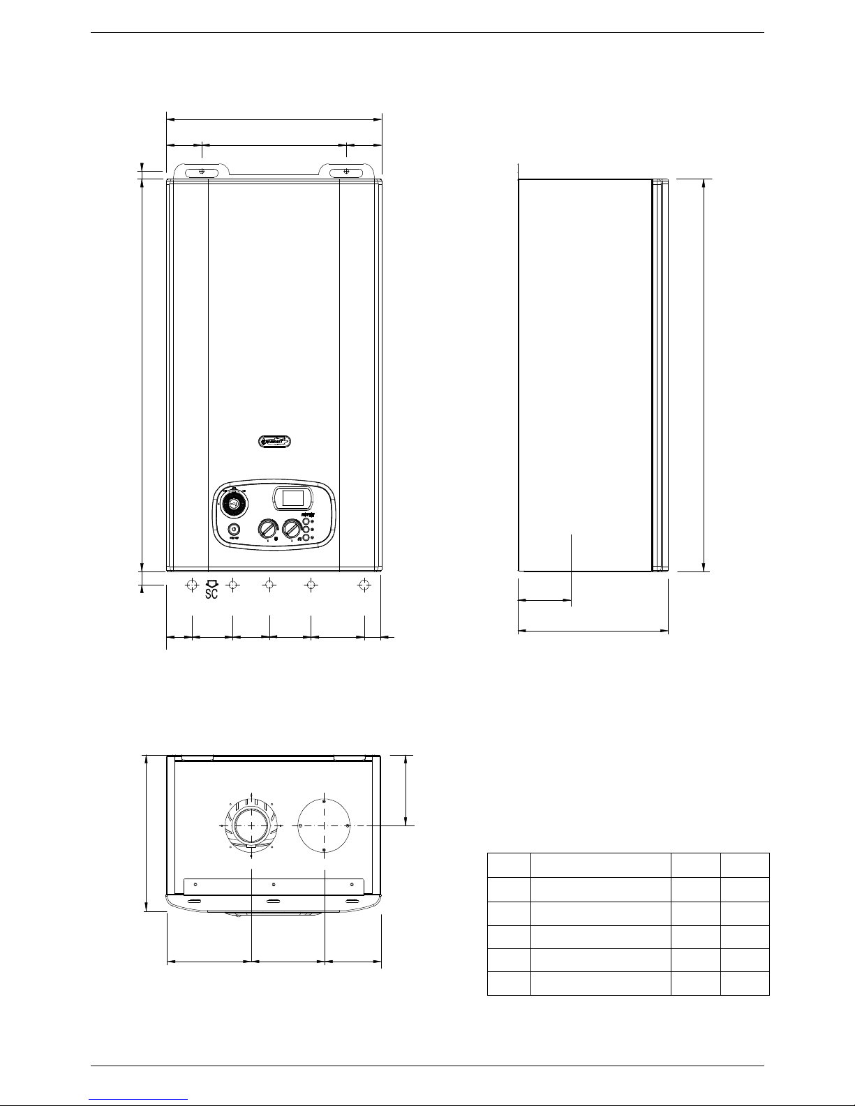
2.2 Dimensions - RKR 24 – RKR 28
LEGEND
HR HEATING RETURN Ø mm
22
HF HEATING FLOW Ø mm
22
G GAS Ø mm
15
CWI COLD WATER INLET
Ø mm 15
HWO HOT WATER OUTLET
Ø mm 15
CD CONDENSATE DRAIN Ø mm
25
TECHNICAL CHARACTERISTCS
7
110137163
310
132
730
HF
CWI
G
HR HWO
7049 78 80 102 31
310
730
111.5187111.5
48.5 313 48.5
105
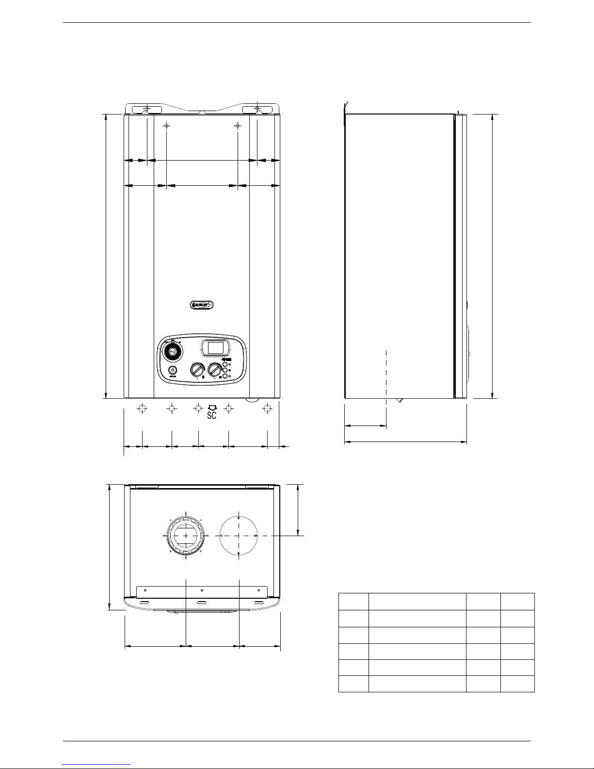
RKR 34
LEGEND
HR HEATING RETURN Ø mm
22
HF HEATING FLOW Ø mm
22
G GAS Ø mm
15
CWI COLD WATER INLET
Ø mm 15
HWO HOT WATER OUTLET
Ø mm 15
CD CONDENSATE DRAIN Ø mm
25
TECHNICAL CHARACTERISTCS
8
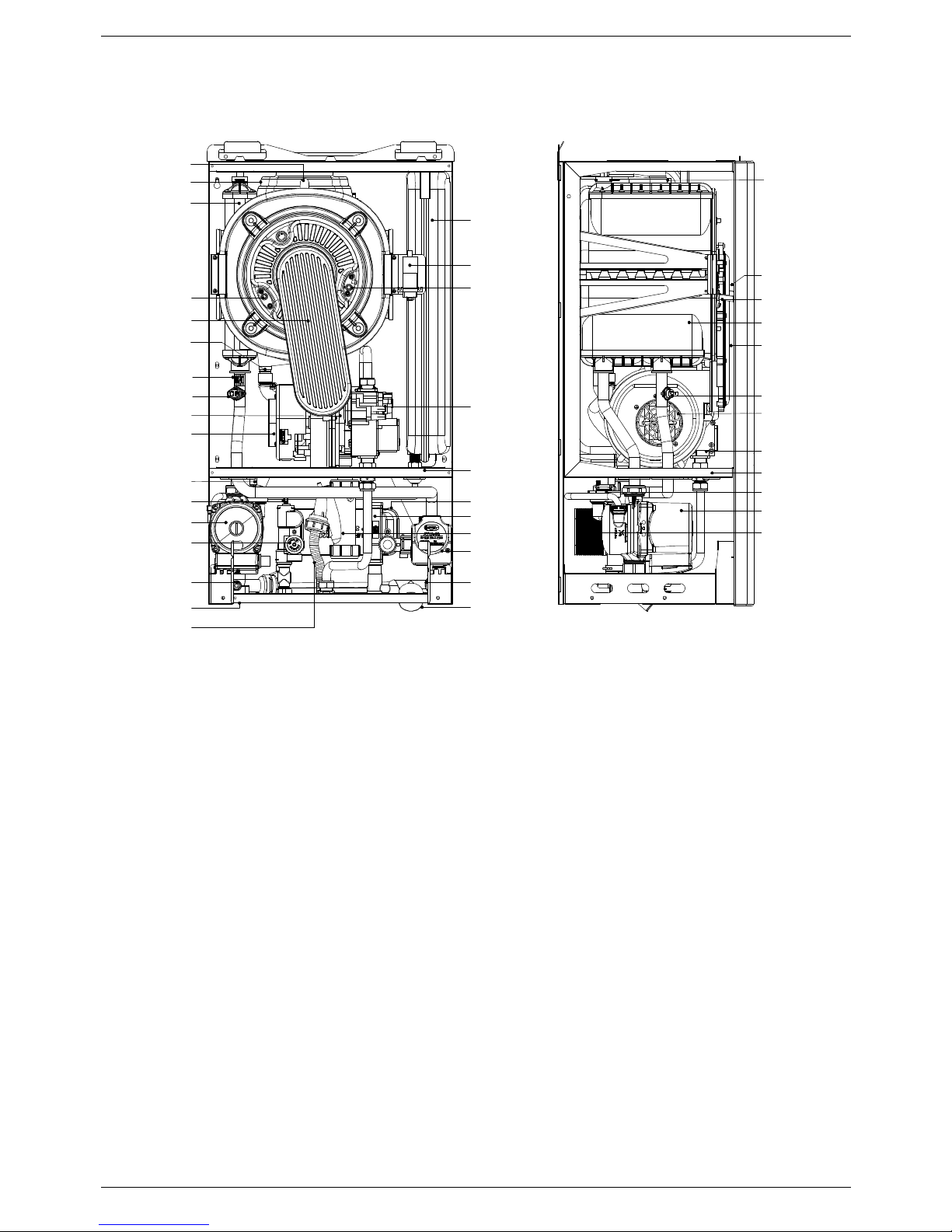
2.3 Internal parts of the boiler
2
16
4
5
6
12
14
25
9
28
11
1
4
8
11
22
14
10
6
7
20
21
27
26
28
12
1
18
9
23
19
16
2
3
17
5
25
24
13
15
LEGEND
1. PRIMARY CONDENSING HEAT EXCHANGER
2. PREMIX BURNER UNIT (GAS MANIFOLD + BURNER)
3. CONDENSATE DRAIN PIPE
4. IONISATION ELECTRODE
5. IGNITION ELECTRODE
6. FAN
7. VENTURI
8. IGNITION TRANSFORMER
9. ELECTRONIC GAS VALVE
10. 3 BAR PRESSURE RELIEF VALVE - HTG CIRCUIT
11. AUTOMATIC AIR VENT VALVE
12. HEATING SAFETY THERMOSTAT
13. HEATING SENSOR
14. PUMP WITH AIR VENT
15. WATER PRESSURE SWITCH
16. FLUE HOOD
17. SAFETY THERMO FUSE
18. EXPANSION VESSEL
19. D.H.W. SENSOR
20. CONDENSATE TRAP
21. WATER PRESSURE GAUGE
22. AUTOMATIC BY-PASS
23. CONDENSATE DRAIN PIPE
24. SYSTEM DRAIN VALVE
25. ROOM SEAL CHAMBER BACK SIDE
26. 3-WAY VALVE
27. ELECTRONIC FLOWSWITCH
28. DHW EXCHANGER
TECHNICAL CHARACTERISTCS
9
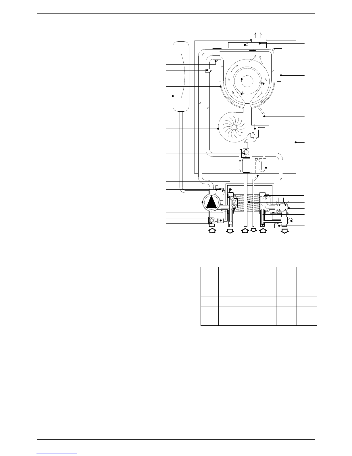
2.4 Water circuit
LEGEND
1.
PRIMARY CONDENSING HEAT
EXCHANGER
2.
PREMIX BURNER UNIT (GAS
MANIFOLD+BURNER)
3.
CONDENSATE DRAIN PIPE
4.
IONISATION ELECTRODE
5.
IGNITION ELECTRODE
6.
FAN
7.
VENTURI
8.
IGNITION TRANSFORMER
9.
ELECTRONIC GAS VALVE
10.
3 BAR PRESSURE RELIEF VALVE - HTG CIRCUIT
11.
AUTOMATIC AIR VENT VALVE
12.
HEATING SAFETY THERMOSTAT
13.
HEATING SENSOR
14.
PUMP WITH AIR VENT
15.
WATER PRESSURE GAUGE
16.
FLUE HOOD
17.
SAFETY THERMO FUSE
18.
EXPANSION VESSEL
19.
D.H.W. SENSOR
20.
CONDENSATE TRAP
21.
WATER PRESSURE SWITCH
22.
AUTOMATIC BY-PASS
23.
CONDENSATE DRAIN PIPE
24.
SYSTEM DRAIN VALVE
25.
ROOM SEAL CHAMBER BACK SIDE
26.
FLOW LIMITER
27.
ELECTRONIC FLOWSWITCH
28.
DHW EXCHANGER
29.
3-WAY VALVE
LEGEND
HR HEATING RETURN Ø mm
22
HF HEATING FLOW Ø mm
22
G GAS Ø mm
15
CWI COLD WATER INLET
Ø mm 15
HWO HOT WATER OUTLET
Ø mm 15
CD CONDENSATE DRAIN Ø mm
25
7
12
1
28
29
27
14
24
10
11
20
9
6
4
5
19
16
2
3
17
18
26
25
23
G CWI HFHR HWO
SC
22
8
21
15
13
TECHNICAL CHARACTERISTCS
10
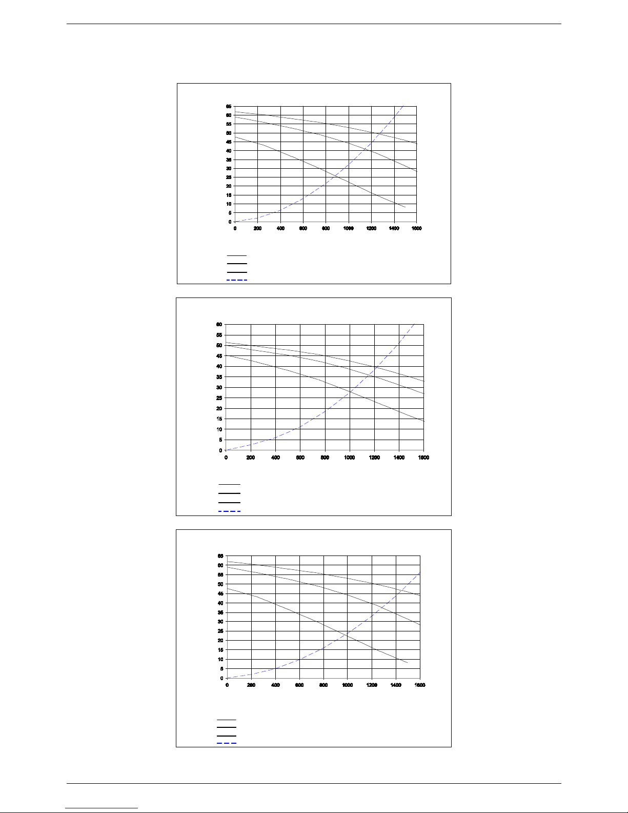
2.5 Circulation pump head/flow graph
I
II
III
Appliance Loss
Pump head at minimum speed
I
II
Pump head at second speed
Pump head at maximum speed
III
Flow l/h
Head (kPa)
RKR 24
III
II
I
Flow l/h
III
Pump head at maximum speed
Pump head at second speed
II
I
Pump head at minimum speed
Appliance Loss
Head (kPa)
RKR 28
Pump head at minimum speed
I
II
Pump head at second speed
Pump head at maximum speed
III
Appliance Loss
Flow l/h
I
II
III
Head (kPa)
RKR 34
TECHNICAL CHARACTERISTCS
11
2.6 DIGITECH 2® printed circuit board – SM30003
Technical characteristics
Adjustments possible by service personnel only
• Standard (30/80°C) / reduced (25-40°C) central h eating temperature
• Water hammer prevention function
• Central Heating timer - (adjustable from 0 to 7,5 minutes)
• Central Heating pump overrun timer
• Domestic Hot Water pump overrun timer
• Minimum Gas pressure setting
• Maximum Heating Load
• Heating output rising time
User settings
• On/Off
• Heating Temperature setting (30-80°C) – (25-40°C)
• D.H.W. temperature setting (35-60°C)
• Summer only mode / Winter only mode / Summer + Winter mode selection
Operation/Functions display
• Lock-Out
• Water deficiency indicator
• Temperature display
When the boiler is switched off at the switch on the control panel, the word OFF appears on the
display. The D.H.W and central heating frost protection system, nevertheless, remain enabled. If the
boiler was previously on, it is switched off and the post-ventilation, pump overrun , circulation pump
and three-way valve inactivity protection functions are enabled.
The remote control, where fitted, remains active and illuminated.
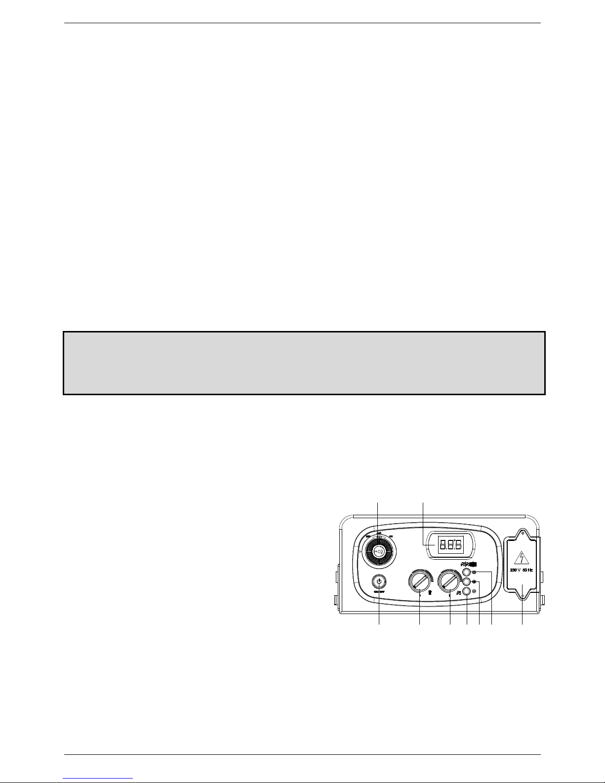
2.7 Control panel
LEGEND
1. ON/OFF BUTTON
2.
HEATING TEMPERATURE CONTROL KNOB
3. D.H.W TEMPERATURE CONTROL KNOB.
4. D.H.W TEMPERATURE BUTTON. KEEP PRESSED FOR 5
SECONDS TO DISPLAY OUTSIDE TEMPERATURE (ONLY IF
OPTIONAL OUTDOOR SENSOR IS FITTED)
5. SERVICE BUTTON.
6. SUMMER, WINTER OR SUMMER/WINTER MODE
SELECTION BUTTON.
7. TERMINAL BOARD FOR EXTERNAL WIRING.
8. TEMPERATURE, ERROR CODE AND OPERATING STATUS
DISPLAY
9. TIME CLOCK (optional)
7654321
89

INSTALLATION INSTRUCTIONS
12
3. INSTALLATION (authorised personnel)
3.1 Reference standard
In GB, the installation must be carried out by a
Gas Safe
Registered Installer. To check for authorised
qualified engineers please contact
Phone Number 0800 408 5500.
It must be carried out in accordance with
the relevant requirements of the:
- Gas Safety Regulations;
- The appropriate Building Regulations either The Building Regulation, The Building Regulations
(Scotland), Building Regulations (Northern Ireland);
- The Water Fittings Regulations or Water Byelaws in Scotland;
- The current I.E.E. Wiring Regulations.
Where no specific instructions are given, reference should be made to the relevant British Standards
Code of Practice.
In GB, the following Codes of Practice apply:
BS 5440:Part1 – Flues
BS 5440:Part2 – Air Supply
BS 5446 Installation of hot water supplies for domestic purposes (1
st
, 2nd and 3rd family gases)
BS 5449 Forced circulation hot water systems
BS 6700 Installation of cold water supplies for domestic purposes (1
st
, 2nd and 3rd family gases)
BS 6798 Installation of gas-fired hot water boilers
BS 6891 Gas Installation
BS 7074 Expansion Vessels and ancillary equipment for sealed water systems
BS 7593 Treatment of water in domestic hot water central heating systems
BS 7671 IEE wiring regulations.
This appliance meets the requirements of:
- UNI EN 677 for GAS-FIRED CENTRAL HEATING BOILERS. SPECIFIC REQUIREMENTS FOR CONDENSING
BOILERS WITH NOMINAL HEAT INPUT ≤ 70 kW
- IPX4D rating for electrical appliances.
- EMC DIRECTIVE 89/336 CEE
- LVD DIRECTIVE 73/23 CEE
- BOILER EFFICIENCY DIRECTIVE 92/42 CEE
Failure to install a gas appliance correctly and in accordance with the above norms could lead to prosecution. It is
in the interest of the installer and safety that the law is complied with.
The manufacturers instructions form an integral part of the installation and should be left with the appliance but do
not over ride in anyway statutory obligations.
INSTALLATION INSTRUCTIONS
13
B
C
A
3.2 Boiler room – Installation requirements
Please refer to local and national standards in force in the Country of destination of the product. In particular the
manufacturer recommends:
The presence of threaded connections on the gas line, require that the room in which the appliance is
installed is ventilated by means of air intakes.
A compartment used to house the appliance must be specifically designed and constructed for the
purpose. An existing compartment or cupboard may be used providing it is suitably modified.
Adequate space for servicing must be provided and it must permit safe installation and termination of
the flue. (See 3.4.1 ‘Compartment Ventilation’)
3.3 Unpacking
■
The materials (cardboard) used for packing the appliance are fully recyclable.
■ It is recommended that the packing material is only removed prior to installing the boiler. The
manufacturer will not be held responsible for damage caused by incorrect storage of the product.
■ Packing materials (plastic bags, polystyrene, nails, etc.) must not be left within reach of children, in that
these items represent a potential hazard.
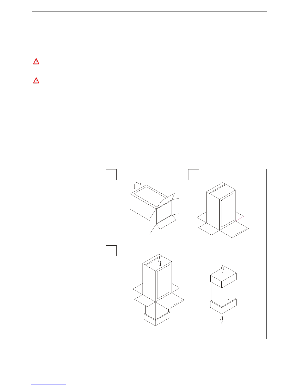
A. Place the packed
appliance on the floor (see fig.
1) making sure that the "up”
arrow is facing down. Remove
the staples and open out the
four flaps of the box.
B. Rotate the boiler 90° while
manually supporting it from
underneath
C. Lift the box and remove the
protections. Lift the boiler by
grasping the rear part and
proceed with the installation.
STORAGE & HANDLING
Please note that prior to
installation the Radiant boilers
should be stored in the
horizontal position with no
more than three boilers to a
stack;
Ensure that the boilers are
stored in dry conditions and
be aware that the carton is a
two man lift;
Fig. 1
INSTALLATION INSTRUCTIONS
14
3.4 Installing the boiler
■ The appliance must be installed
exclusively on a flat vertical solid
wall capable of supporting its
weight.
■ The boiler should be fitted within the
building unless otherwise protected by
a suitable enclosure i.e. garage or
outhouse. (the boiler may be fitted
inside a cupboard, (see 3.4.1
“Compartment Ventilation”).
■ If the boiler is sited in an unheated
enclosure then it is recommended to
leave the power on to give frost
protection (frost protection is active
even with On/Off switch in Off position).
■ If the boiler is installed in a room
containing a bath or shower reference
must be made to the relevant
requirements. The appliance controls
or any related switch or control should
not be within reach while using the bath
or shower.
In GB this is the current I.E.E. Wiring
regulations and Building Regulations;
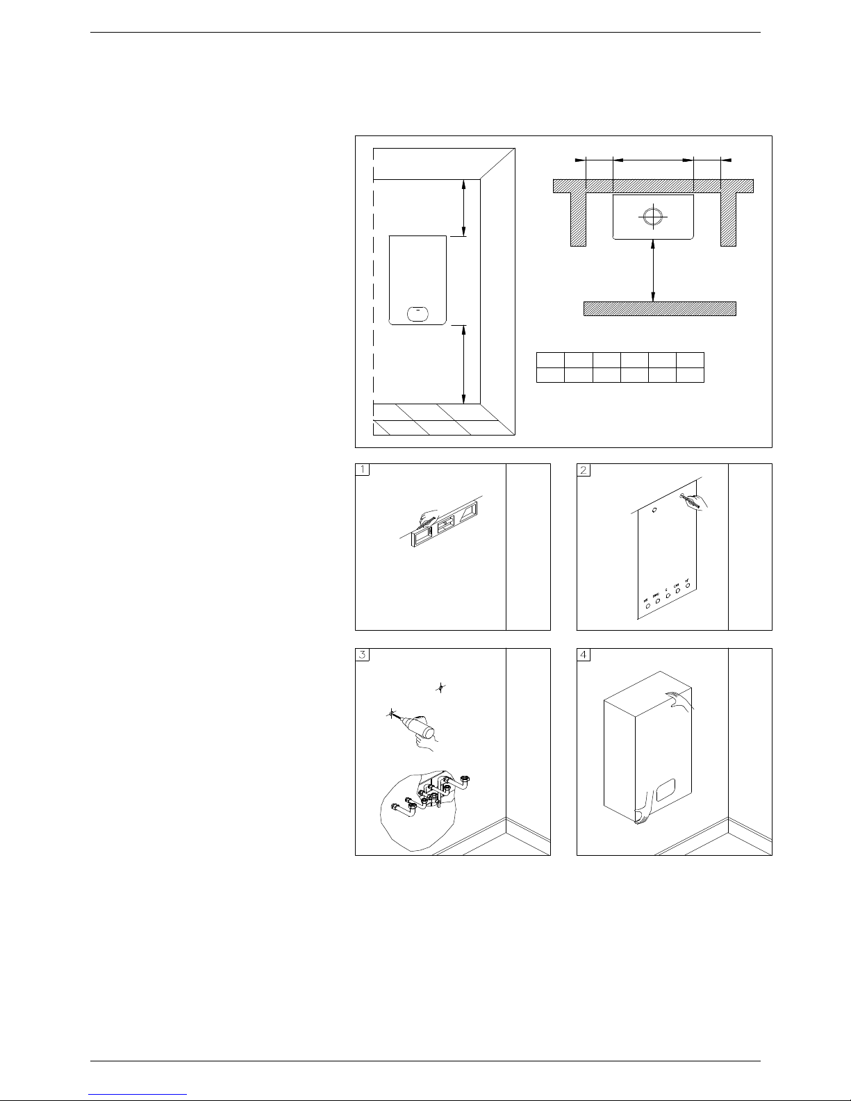
In order to allow access to the interior of
the boiler for maintenance purposes, it is
important that the necessary clearances
indicated in figure 1 are respected. To
make the installation easier, the boiler is
supplied with a template to enable the pipe
connections to be positioned prior to fixing
the appliance to the wall.
To install the boiler, proceed as follows
(see fig. 2):
a. Use a spirit level (of not less than 25
mm long) to mark a horizontal line on
the wall where the boiler is to be fitted.
b. Position the top of the template along
the line drawn with the level, respecting
the distances indicated. Then mark the
centres of the positions of the two wallplugs or anchors. Finally, mark the
positions of the water and gas pipes.
c. Remove the template and install the
domestic hot and cold water pipes, the
gas supply pipe and the central heating
pipes using the fittings supplied with the boiler.
Fix the boiler to the wall using the wall plugs or bracket and connect the pipes.
Compartment Ventilation
Where the appliance is installed in a compartment, no air vents are required.
BS 5440:Part 2 refers to room sealed appliances installed in compartments. The appliance will run sufficiently cool
without ventilation.
MINIMUM DITANCES IN mm
H
A
X
L
Y
X Y L HBA B
20060 60 410 1000 300
Fig. 1
Fig. 2
INSTALLATION INSTRUCTIONS
15
3.5 Water connections
In order to safeguard the heat exchanger and circulation
pump, especially in case of boiler replacement, it is
recommended that the system is hot-flushed to remove
any impurities (especially oil and grease) from the pipes
and radiators.
Make sure that the domestic water and central heating
pipes are not used to earth the electrical system. The
pipes are totally unsuitable for this purpose.
The Isolation Valves provided must be installed
on the heating and D.H.W circuits. This will facilitate all
maintenance and service operations where the boiler
needs to be drained.
■ To prevent vibration and noise coming from the system, do
not use pipes of reduced diameter, short radius elbows or
severe reductions in the cross sections of the water
passages.
■ In order to guarantee the reliability of the boiler and prevent
permanent damage in areas with very high water inlet
pressure a 2.5 bar pressure reducing valve should be fitted.
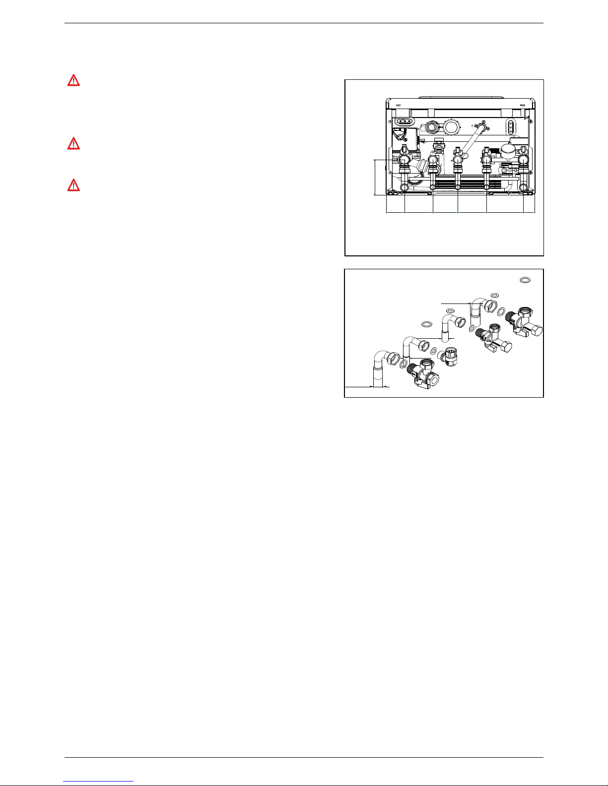
■ To facilitate the installation, the boiler is supplied with a
hydraulic connection kit (see fig.2).
Domestic hot water circuit
■ In order to prevent scaling and eventual damage to the D.H.W
heat exchanger, the mains water supply must not have a
hardness rating of more than 17.5 °Ck. It is nevert heless
advisable to check the properties of the water supply and
install the appropriate treatment devices where necessary.
The cold water supply pressure at the inlet to the boiler must be between 0.5 and 6 bar.
In areas with higher water inlet pressure a pressure reducing valve must be fitted before the boiler.
The frequency of the heat exchanger coil cleaning depends on the hardness of the mains water supply and the
presence of residual solids or impurities, which are often present in the case of a new installation. If the
characteristics of the mains water supply are such that require it to be treated, then the appropriate treatment
devices must be installed, while in the case of residues, an in-line filter should be sufficient.
All D.H.W. circuits, connections, fittings, etc. should be fully in accordance with relevant standards and water
supply regulations.
Guidance G17 to G24 and recommendations R17 to R24 of the Water Regulation Guide.
Central heating circuit
In order to prevent scaling or deposits in the primary heat exchanger, the mains supply water to the heating circuit
must be treated according to the requirements of local standards.
This treatment is indispensable in the case where the circuit is frequently topped-up or when the system is often
either partially or fully drained.
The outlet connection of the boiler safety valve must be connected to a discharge pipe with a continuous fall from
the boiler to outside. It must terminate in a safe position where any water, possibly boiling, can discharge without
causing a hazard. The manufacturer will not be held responsible for flooding or damage caused by the operation of
the safety valve in the case of system overpressure.
Condensate Drain
The condensate drain flexible pipe supplied with the boiler (conforming to UNI EN 677 standard) must be
connected to a proper condensate trap. The condensate discharge into the drainage system is allowed providing a
condensate trap (siphon) is installed.
Any condensate discharge pipe work external to the building (or in an unheated part of it) must be insulated to
protect against frost. Before switching the boiler On, check the correct condensate discharge.
HFCWIGHWOHR
49 78 70 80 102 31
105
Fig. 2
Fig. 1
Ø 15 mm
Ø 22 mm
HF
CWI
HR
HWO
Ø 22 mm
Ø 15 mm

INSTALLATION INSTRUCTIONS
16
3.6 Central heating circuit
The boiler is designed for use in a sealed central heating system in accordance with the requirements of BS 5449 and BS 6798.
The system should be designed to operate with flow temperatures of up to 82°C. When designing the system, the pump head,
expansion vessel size, mean radiator temperature, etc. must all be taken into account. Refer to the pump performance table
for guidelines.
System volume -The 7 litre expansion vessel incorporated into the boiler is generally suitable for most sealed heating
systems however if the system has a larger volume of water it may be necessary to provide extra capacity for expansion.
The boiler is supplied with the following components built in:Pressure relief valve -complying with BS 6759 and set to operate at 3 bars. The outlet connection of the boiler safety valve
must terminate to atmosphere in accordance with current regulations. The manufacturer will not be held responsible for
flooding caused by the operation of the safety valve in the case of system overpressure..
Pressure gauge -To indicates the system pressure to be maintained.
Expansion vessel – Volume 7 litre. Conforming to BS 7074:1 for GB,
By-pass -The boiler incorporates a by-pass, however where all radiators are fitted with thermostatic radiator valves it is
recommended an automatic system by-pass is fitted.
Additional expansion
vessel (if required)
Double check valve assy
Temperature/pressure
relief valve
Boiler
Automatic air vent
Heating return
System
drain tap
Note: A drain tap should be installed at the lowest point of the
heating circuit and beneath the appliance
Note: If required, an automatic
by-pass is preferred
Radiator
valve
Filling point
DHW outlet
Pressure reducing
valve (supplied)
Mains water
inlet
Static head of system
Make up vessel
Heating by-pass
(if required)
Lockshield valve
Filling the central heating system – figs. 2-3
The system design pressure (cold) should be set to 1.5 bar. This pressure is equivalent to a static head of 15.4 metres of
water.
Provision should be made to replace water lost from the system during servicing etc. as shown in Figs. 2 and 3. The position
for connecting an alternative make-up vessel is indicated in Fig. 1. A double check valve assembly must be used. as shown in
Fig. 3.
Filling of the system must be carried out in a manner approved by the local Water Undertaking (GB: Guidance G24.2 and
Recommendation R24.2 of the Water Regulation Guide). Where allowed the system may be filled via a temporary connection
as shown in Fig. 2. After filling, always disconnect the flexible hose of the filling loop.
All fittings used in the system must be able to withstand pressures up to 3 bar.
Drain taps (to BS 2879) must be used to allow the system to be completely drained.
Double
check valve
assembly
Test
cock
Feed cistern to be
located above highest
point in the system
Overflow
Heating
circuit
return
Test
cock
Double
check valve
assembly
Stop
valve
Mains water
supply
Mains
water
supply
Stop
valve
Filling loop
temporarily
Hose
unions
Heating
circuit
return
In
order to prevent scaling or deposits in the primary heat exchanger, the water in the heating circuit must be treated
according to the requirements of standard.
This treatment is indispensable in the case where the circuit is frequently topped-up or when the system is often either partially
or fully drained. Frequent topping-up of the system should be avoided and normally indicates a leak within the heating system.
Fig. 1
Fig. 2
Fig. 3
INSTALLATION INSTRUCTIONS
17
3.7 Condensate drain
FAILURE TO INSTALL THE CONDENSATE
DISCHARGE PIPEWORK CORRECTLY WILL
AFFECT THE RELIABLE OPERATION OF THE
BOILER. The condensate discharge pipe MUST NOT
RISE at any point along its length. There MUST be a
fall of AT LEAST 2.5° (50mm per metre) along the
entire run.
CAREFUL ATTENTION IS REQUIRED TO MINIMISE
THE RISK OF FREEZING DURING PROLONGED
COLD SPELLS.
I. The boiler condensate outlet terminates in a 25 mm
flexible plastic pipe for connection to a plastic pipe
which should generally discharge internally into the
household drainage system. If this is not possible,
discharge into an outside drain or suitable soak-away is
acceptable.
2. Ensure the discharge of condensate complies with
any national or local regulations in force.
BS 6798:2000 & Part H I of the Building Regulations
give further guidance.
3. The discharge pipe should be run in a proprietary
drain pipe material e.g. PVC, PVC-U, ABS, PVC-C or
PP and take the shortest practicable route to a
termination point.
4. Metal pipe work is NOT suitable for use in
condensate discharge systems.
5. The pipe should be a minimum of 22 mm diameter
and must be supported using suitably spaced clips to
prevent sagging.
6. Any pipe fitted externally should not exceed 3
metres.
7 Any condensate discharge pipe work external to the
building (or in an unheated part of it e.g. garage) must
be insulated to protect against frost. It is also
recommended that the pipe diameter is increased to
32mm.
8. If the boiler is fitted in an unheated location the entire
condensate discharge pipe should be treated as an
external run.
9. In alI cases discharge pipe must be installed to aid
disposal of the condensate. To reduce the risk of
condensate being trapped or freezing, as few bends
and fittings as possible should be used.
10. When discharging condensate into a soil stack or
waste pipe the effects of existing plumbing must be
considered. If soil pipes or waste pipes are subjected to
internal pressure fluctuations when WC's are flushed or
sinks emptied then back-pressure may force water out
of the boiler trap and cause appliance lockout.
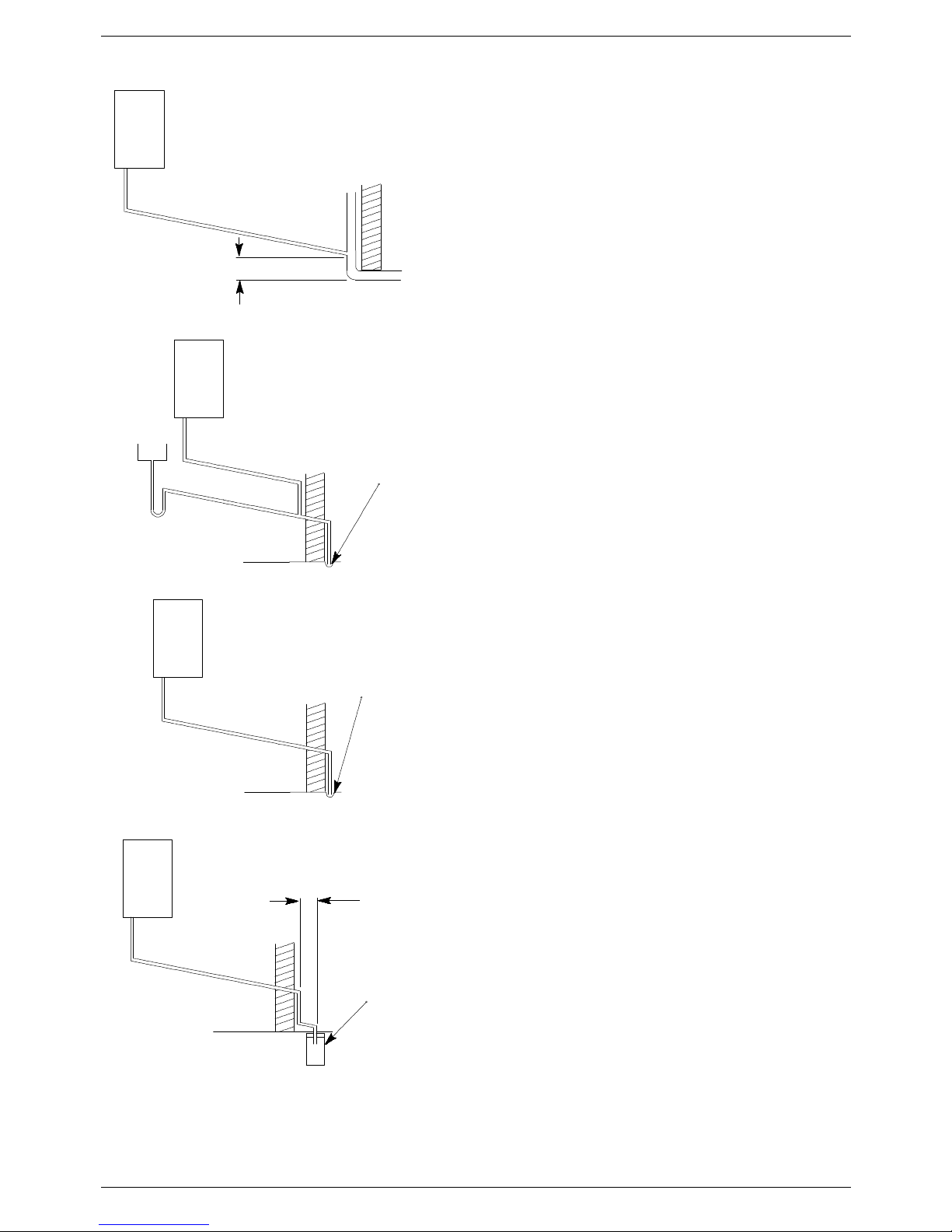
Examples are shown of the following methods of
termination:-
i) to an internal soil & vent pipe
ii) via an internal discharge branch (e.g. sink waste)
iii) to a drain or gully
iv) to a purpose made soak away
450mm min
Holes in the soak-away must
face away from the building
500mm min
External termination to a purpose made soak-away
External termination to a drain or gully
Pipe must terminate above
water level but below
surrounding surface
5
0
m
m
p
e
r
m
e
t
r
e
o
f
p
i
p
e
r
u
n
2
.
5
°
M
i
n
i
m
u
m
f
a
l
l
5
0
m
m
p
e
r
m
e
t
r
e
o
f
p
i
p
e
r
u
n
2
.
5
°
M
i
n
i
m
u
m
f
a
l
l
Boiler
Pipe must terminate above
water level but below
surrounding surface
5
0
m
m
p
e
r
m
e
t
r
e
o
f
p
i
p
e
r
u
n
2
.
5
°
M
i
n
i
m
u
m
f
a
l
l
External termination via internal discharge
branch e.g. sink waste - downstream
Sink
2
.
5
°
M
i
n
i
m
u
m
f
a
l
l
5
0
m
m
p
e
r
m
e
t
r
e
o
f
p
i
p
e
r
u
n
Termination to an internal soil and vent pipe
Boiler
Boiler
Boiler
 Loading...