

Page 1

RBS 24 - RAD - ING - Manual - 1709.1_MIAB2013_R7
Installation, Use
and Maintenance Manual
for model
0476
RBC 24
Open chamber boiler with built-in DHW
heat exchanger
Page 2

2
RBS 24 - RAD - ING - Manual - 1709.1_MIAB2013_R7
RBC 24_EN
TABLE OF CONTENTS
TABLE OF CONTENTS
INTRODUCTION 4
1. INSTALLER SECTION 7
1.1. INSTALLATION 8
1.1.1. GENERAL INSTALLATION WARNINGS 8
1.1.2. BOILER LOCATION ENVIRONMENTAL REQUIREMENTS 8
1.1.3. REFERENCE LEGISLATION 9
1.1.4. UNPACKING 10
1.1.5. OVERALL DIMENSIONS 11
1.1.6. JIG 11
1.1.7. POSITIONING AND MINIMAL TECHNICAL SPACES 12
1.1.8. CIRCULATOR PREVALENCE/FLOW DIAGRAM 13
1.1.9. HYDRAULIC CONNECTION 14
1.1.10. SYSTEM FILLING 15
1.1.11. ANTI-FREEZE PROTECTION 16
1.1.12. GAS CONNECTION 17
1.1.13. ELECTRICAL CONNECTION 17
1.1.14. OPTIONAL ELECTRICAL CONNECTIONS 18
1.1.15. FUME EXHAUST FITTINGS 19
1.1.16. TYPES OF INSTALLATION 20
2. SUPPORT CENTER SECTION 23
2.1. FIRST START-UP 24
2.1.1. PRELIMINARY OPERATIONS FOR FIRST START-UP 24
2.1.2. BOILER COMMISSIONING 25
2.1.3. GAS PRESSURE CHECK AND CALIBRATION 26
2.1.4. ACCESSING AND PROGRAMMING THE PARAMETERS 28
2.1.5. PARAMETER TABLE MIAB2013 31
2.1.6. HEAT CAPACITY / GAS PRESSURE DIAGRAM 35
2.2. MAINTENANCE 36
2.2.7. GENERAL MAINTENANCE WARNINGS 36
2.2.8. TECHNICAL DATA 37
2.2.9. TECHNICAL ASSEMBLY 41
2.2.10. HYDRAULIC BOARD 42
2.2.11. WIRING DIAGRAM 43
2.2.12. ACCESSING THE BOILER 44
2.2.2. ACCESSING THE ELECTRONIC BOARD 45
2.2.14. SYSTEM EMPTYING 46
2.2.15. FAULT SIGNALLING CODES 47
Page 3

3
RBS 24 - RAD - ING - Manual - 1709.1_MIAB2013_R7
RBC 24_EN
TABLE OF CONTENTS
2.2.3. CHIMNEY SAFETY 50
2.2.16. ACTIVE FUNCTIONS SIGNALLING CODES 51
2.2.17. GAS TYPE TRANSFORMATION 52
3. USER SECTION 53
3.1. USE 54
3.1.1. GENERAL USE WARNINGS 54
3.1.2. CONTROL PANEL 55
3.1.2. DISPLAY ICONS 56
3.1.3. INFO MENU DISPLAY DATA 57
3.1.4. START-UP 58
3.1.5. OPERATING MODE 58
3.1.6. INFORMATIONAL NOTE ON ANTI-FREEZE FUNCTION 59
3.1.7. SYSTEM FILLING 60
3.1.8. FAULT SIGNALLING CODES 61
3.1.9. ACTIVE FUNCTIONS SIGNALLING CODES 63
3.1.7. MAINTENANCE 64
3.1.8. COVER CLEANING 64
3.1.9. DISPOSAL 64
Page 4
4
RBS 24 - RAD - ING - Manual - 1709.1_MIAB2013_R7
_Prefazione_EN
1.
INTRODUCTION
WARNING
Before starting any operation it is mandatory to
read this instruction manual, in relation to the
activities to be carried out as described in each
relevant section. Proper operation and optimal
performance of the boiler are ensured by strict
compliance with all the instructions given in this
manual.
The installation, use and maintenance manual is
an integral and essential part of the product and
must be delivered to the user.
MANUAL USERS
The manual users are all those who install, use
and maintain the boiler.
The boiler must be used and accessed only by
qualified operators that fully read and understood
the use and maintenance manual, paying particular
attention to the warnings.
READING AND SYMBOLS OF THE MANUAL
To ease the understanding of this manual, recurrent
symbols where used, in particular:
› On the outer margin of the page is placed a
thumb index indicating the type of user to which
the instructions in that section address.
› The titles are differentiated by thickness and size
in accordance with their hierarchy.
› The images contain important parts described in
the text, marked with numbers or letters.
› (See chap “chapter name”): this entry indicates
another section in the Manual that you should
refer to.
› Device: this term is used referring to the boiler.
DANGER
It identifies an information related to a
general danger that if not complied with, may cause
serious personal damage or even death.
ATTENTION
It identifies an information that if not
complied with may cause small or medium level
lesions to the person or serious deterioration to the
boiler.
WARNING
It identifies a precaution information that
must be observed in order to avoid damaging the
machine or parts of it.
MANUAL STORAGE
The manual must be carefully stored and replaced
in case of deterioration and/or low legibility.
If you misplace the use and maintenance manual,
you can request it from the Technical Support
Centre giving the serial number and model of the
boiler indicated on the plate placed on the right
side of its casing.
As an alternative, the use and maintenance manual
can be downloaded free from the on-line site www.
radiant.it, accessing the “download” section and
entering the boiler model.
INTRODUCTION
Page 5

5
RBS 24 - RAD - ING - Manual - 1709.1_MIAB2013_R7
_Prefazione_EN
1.
MANUFACTURER WARRANTY AND
RESPONSIBILITY
The warranty of the Manufacturer is provided only
through its own authorized Technical Support
Centres, listed for each Region and Provence on
the site www.radiant.it, and covers all conformity
defects at the moment of sale.
The technical and functional features of the device
are ensured by its use in compliance:
1. with the use and maintenance instructions
contained in the manuals accompanying the
product, the content of which the customer
certifies that he is aware;
2. with the conditions and purposes to which
assets of the same type are intended.
For more information on the warranty validity,
its duration, the obligations and the exemptions,
please consult the First start-up certificate
attached to this manual.
The manufacturer reserves:
› the right to modify the tools and relative
technical documentation without any obligation
to third parties; neither will the company be
held responsible for any inaccuracies in this
handbook deriving from printing or translation
errors;
› the material and intellectual ownership of
this manual and forbids its distribution and
duplication, even partial, without prior written
authorization.
PRODUCT CONFORMITY
RADIANT BRUCIATORI spa declares that its gas
boilers comply with the European Directives and
with the requirements provided in the European
standards below:
› Eco-design Directive 2009/125 CE,
› Energy labeling Directive 2010/30/CE,
› EU regulation 811/2013,
› EU regulation 813/2013,
› Gas Directive 2009/142/CE,
› Electromagnetic compatibility Directive 2014/30/
CE,
› Performance Directive 92/42/CE,
› Low voltage Directive 2014/35/CE.
The materials used such as copper, brass, stainless
steel create a homogeneous, compact and
functional assembly, easy to install and manage.
In its simplicity, the boiler is equipped with all
accessories necessary to render it a veritable
independent heating unit. All boilers are tested and
delivered with a quality certificate signed by the
tester.
INTRODUCTION
Page 6

Page 7

The installation operations described in this section should
be performed only by qualified personnel, having the
appropriate technical training in the field for the installation
and maintenance of components of civil and industrial
domestic hot water production and heating plants.
1. INSTALLER SECTION1. INSTALLER SECTION
Page 8
8
RBS 24 - RAD - ING - Manual - 1709.1_MIAB2013_R7
1 Avvertenze generali per l'installazione_Locale caldaia_trad_EN
1. INSTALLATION
INSTALLER
1.1. INSTALLATION
1.1.1. GENERAL INSTALLATION
WARNINGS
ATTENTION
This machine may be used only for the
purpose for which it has been designed: heat water
to a temperature below boiling point at atmospheric
pressure. Any other use is considered wrong and
dangerous. The manufacturer is excluded from
any contractual or out of contract responsibility for
damage caused to people, animals or property due to
errors during installation.
ATTENTION
This boiler should be installed only
by qualified personnel, having the appropriate
technical training in the field for the installation and
maintenance of components of civil and industrial
domestic hot water production and heating plants.
ATTENTION
After having removed the packing, make
sure the equipment is intact. In case of doubt, do not
use the equipment and contact the supplier.
BEFORE INSTALLING THE BOILER, THE
INSTALLER MUST MAKE SURE THAT THE
FOLLOWING CONDITIONS ARE MET:
› The device is connected to a heating plant and a
water supply network appropriate for its power
and performance.
› The location must be properly vented through an
air vent.
› The air vent must be placed at floor level to
prevent it from being obstructed, protected by a
grid that does not hamper the useful section of
passage.
› The device is suitable for use with the type of
gas available by checking the boiler data plate
(placed on the inner side of the front casing.
› Make sure that the tubes and couplings are
perfectly sealed, without any gas leaks.
› Make sure that the grounding system works
properly.
› Make sure that the electrical systems is suitable
for the maximum power absorbed by the
equipment, value indicated on the data plate.
WARNING
Use only original RADIANT optional or kit
accessories (including electrical).
1.1.2. BOILER LOCATION
ENVIRONMENTAL
REQUIREMENTS
The device's installation location should be vented
due to the presence of threaded joints on the gas
adduction line. The location should be therefore
provided with vents as to ensure air exchange, with
output grid in the natural accumulation area of
eventual gas losses.
WARNING
If the temperature in the boiler installation
location goes below -10° centigrades, please fill
the plant with anti-freeze liquid and insert and
electrical resistances kit (see chapter ‘ANTI-FREEZE
PROTECTION’).
WARNING
The manufacturer will not be held
responsible for damages caused by incorrect
installation not in conformity with the over mentioned
Page 9

9
RBS 24 - RAD - ING - Manual - 1709.1_MIAB2013_R7
1 Avvertenze generali per l'installazione_Locale caldaia_trad_EN
1. INSTALLATION
INSTALLER
instructions and not protected adequately from the
freeze.
1.1.3. REFERENCE LEGISLATION
The installation must be realized according to
the requirements of current legislation and in
compliance with local technical regulations,
according to the indications of the good technique.
Page 10
10
RBS 24 - RAD - ING - Manual - 1709.1_MIAB2013_R7
1 Disimballo_murale_EN
1. INSTALLATION
INSTALLER
1.1.4. UNPACKING
WARNING
Please unpack the boiler just before
installing it. The Company is not responsible for
the damages caused to the device due to incorrect
storage.
WARNING
The packing elements (cardboard box,
wooden crate, nails, fasteners, plastic bags, expanded
polystyrene, etc.) must be kept out of the reach of
children as they may be dangerous. Therefore they
should be dismantled suitably differentiating them in
accordance with the standards in force.
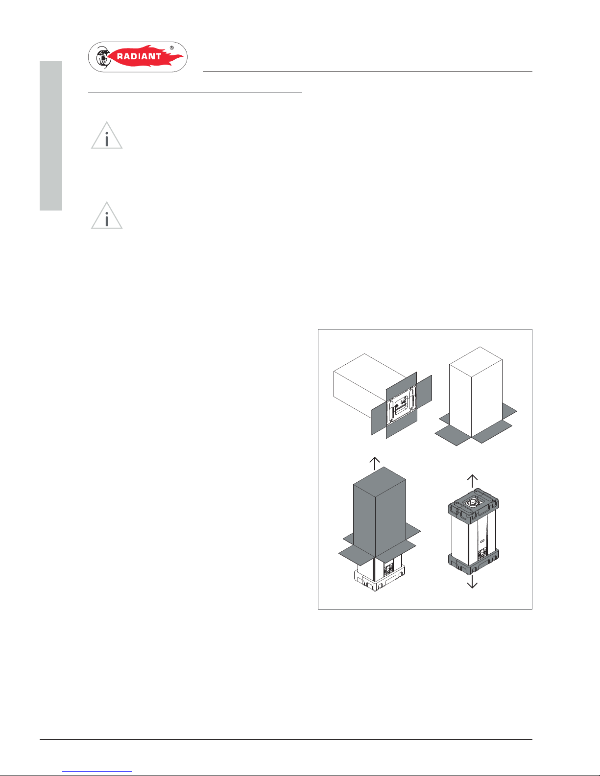
To unpack the boiler, proceed as follows:
› Place the packed boiler on the floor (fig. 1-A) and
remove the fasteners opening the four flaps of
the box outwards.
› Turn the boiler at 90° holding it with your hand
(fig. 1-B).
› Lift the box (fig. 1-C) and remove the guards (fig.
1-D).
C
B
D
A
fig. 1
Page 11

11
RBS 24 - RAD - ING - Manual - 1709.1_MIAB2013_R7
1 Dimensioni_RBC 24_NC_R7_EN
1. INSTALLATION
INSTALLER
1.1.5. OVERALL DIMENSIONS
1.1.6. JIG
205
180
730
410
320
805
49 78 70 80 102 31
120
RCG F A
R- RETURN Ø 3/4”
C - HOT Ø 1/2”
G- GAS Ø 3/4”
F- COLD Ø 1/2”
A- INFEED Ø 3/4”
Page 12
12
RBS 24 - RAD - ING - Manual - 1709.1_MIAB2013_R7
1 Spazi tecnici minimi e posizionamento_murale_EN
1. INSTALLATION
INSTALLER
1.1.7. POSITIONING AND MINIMAL
TECHNICAL SPACES
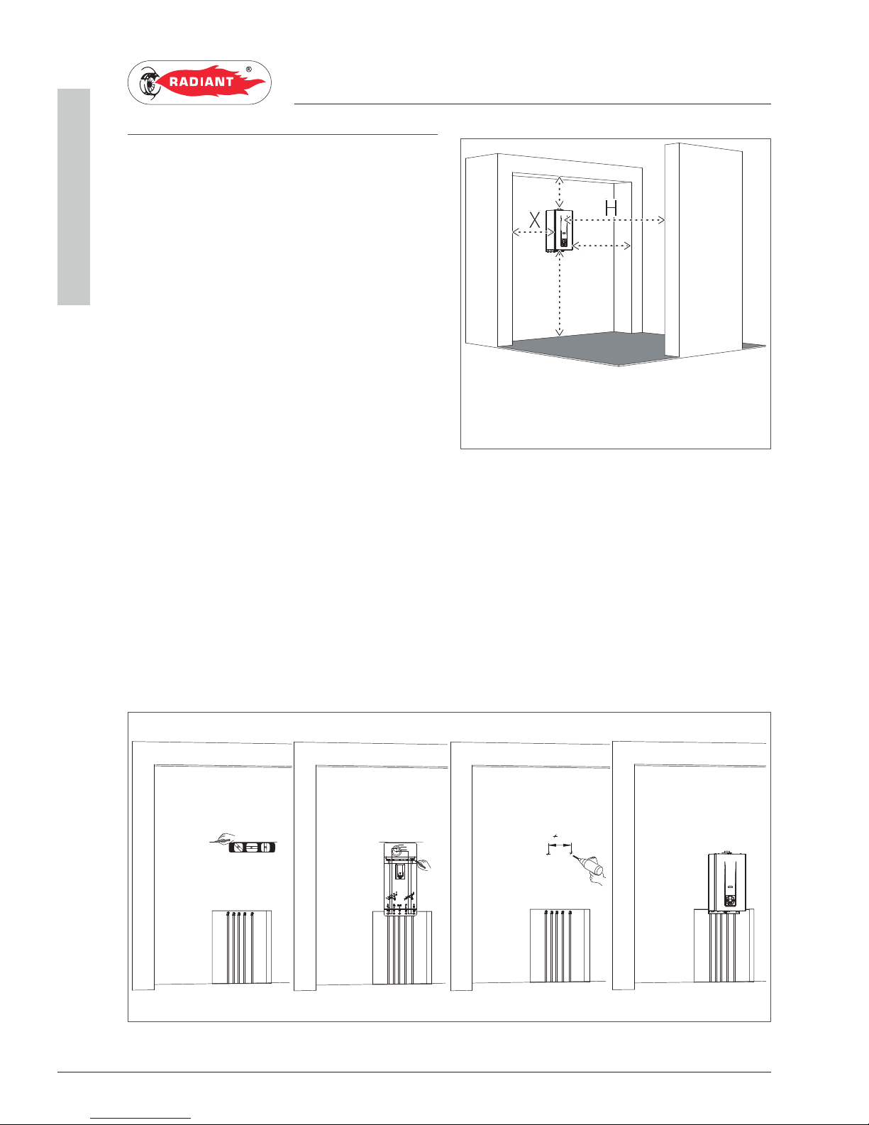
The boiler must be installed only on a vertical solid
wall, able to sustain its weight.
In order to allow the access inside the boiler for
maintenance operations, you have to respect the
minimum technical spaces indicated in figure 1.
To facilitate the installation, the boiler is provided
with a jig that allows setting in advance the
connections to the tubes offering you the possibility
of connecting the boiler to completed masonry
works.
For machine positioning, proceed as follows (see fig. 2):
1. Trace a line using a spirit level (min. length 25 cm) on the installation wall.
2. place the top of the jig along the traced line respecting the distances of the water connections; then
mark the two points to insert the two knobs or the fasteners, then trace the points for the fume
exhaust fittings;
3. remove the jig and drill the wall;
4. hang the device using the knobs or the bracket and perform the connections.
3
1
42
70 80 10249 3178
Ø80
Ø125
Ø100
35826 26
54 54
821
681
699
302
785
H
B
A
Y
X
A - 200 mm
B - 300 mm
X - 60 mm
Y - 60 mm
H - 1000 mm
fig.1
fig.2
Page 13
13
RBS 24 - RAD - ING - Manual - 1709.1_MIAB2013_R7
1 Diagramma portata-prevalenza circolatore_RBS 24_HE_EN
1. INSTALLATION
INSTALLER
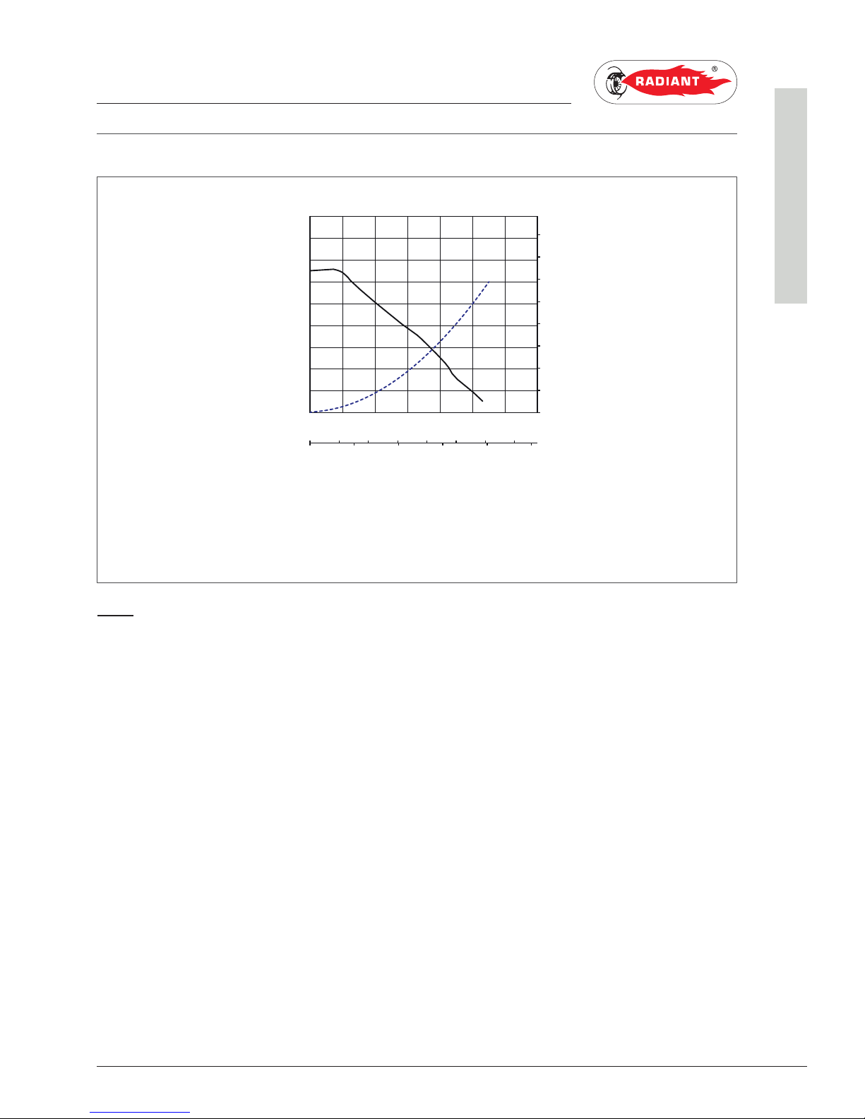
1.1.8. CIRCULATOR PREVALENCE/FLOW DIAGRAM
Circulator priority maximum speed
- - - - Boiler load loss
Wilo-Yonos PARA MSL 12/6B
0 0,4 0,8 1,2 1,6 2,0 2,4
0 0,1 0,2 0,3 0,4 0,5 0,6 0,7
02468
0
1
2
3
4
5
6
7
8
0
10
20
30
40
50
70
60
80
p/kPa
H/m
Q/m³/ h
Q/l/s
Q/Igpm
PREVALENCE
FLOW RATE
Page 14
14
RBS 24 - RAD - ING - Manual - 1709.1_MIAB2013_R7
1 Allacciamento idraulico_combinata_EN
1. INSTALLATION
INSTALLER
1.1.9. HYDRAULIC CONNECTION
DANGER
Make sure that the tubes of the water and
heating plant are not used as grounding system for
the electrical plant. There are not suitable for such
use.
WARNING
To prevent voiding the warranty and to
ensure the proper operation of the boiler, please
wash the plant (if possible when hot) with suitable
pickling or descaling solutions in order to remove the
impurities coming from tubes and radiators.
WARNING
If the boiler is installed in a hydrostatic
position lower than those of the user devices
(radiators, fan coils, etc.), mount the shut-off valves
on the domestic water heating circuit to ease the
performance of the maintenance operations if it is
necessary only to empty the boiler.
WARNING
When connecting the equipment to
water supply, avoid excessive bending and recovery
operations from any off axis positioning that may
damage the tubes causing leaks, malfunction or
early wear.
WARNING
In order to avoid any vibrations and noises,
do not use tubes with small diameters or elbows with
small radius and significant cut-off of the passage
sections.
WARNING
Connect the boiler safety drains to a
discharge funnel. The manufacturer is not responsible
for any floods due to safety valve opening in case of
plant overpressure.
DOMESTIC CIRCUIT
In order to prevent limestone build-up and damages
to the domestic water heat exchanger, the hardness
of the domestic supply water should not exceed 15
°f. However, please check the characteristics of the
water used and install suitable treating devices.
The heat exchanger coil cleaning frequency
depends on the hardness of the supply water and on
the presence of solid residues or impurities inside
the water that are often present in case of recently
installed plants. Based on the characteristics of
the infeed water, you should install suitable water
treating devices, for residues presence please
install a line filter.
The pressure of the cold infeed water should be
between 0.5 and 6 bar. In case of greater pressure
values, please install a pressure reducer upstream
from the boiler.
HEATING CIRCUIT
In order to avoid any scale or deposits on the
primary exchanger, the hardness of the heating
circuit infeed water should not exceed 25 °f.
However, please check the characteristics of the
water used and install suitable treating devices.
This treatment is mandatory if frequent episodes
of return water or partial or total emptying of the
plant occur.
WARNING
In case the boiler is installed as part of
a low temperature circuit, please install a safety
thermostat on the heating flow, which can stop
the boiler activity in case of high heating flow
temperature. The company assumes no liability for
damage caused to persons or for failure to comply
with these instructions.
Page 15
15
RBS 24 - RAD - ING - Manual - 1709.1_MIAB2013_R7
1 Riempimento dell'impianto_RBS_HE_R7_EN
1. INSTALLATION
INSTALLER
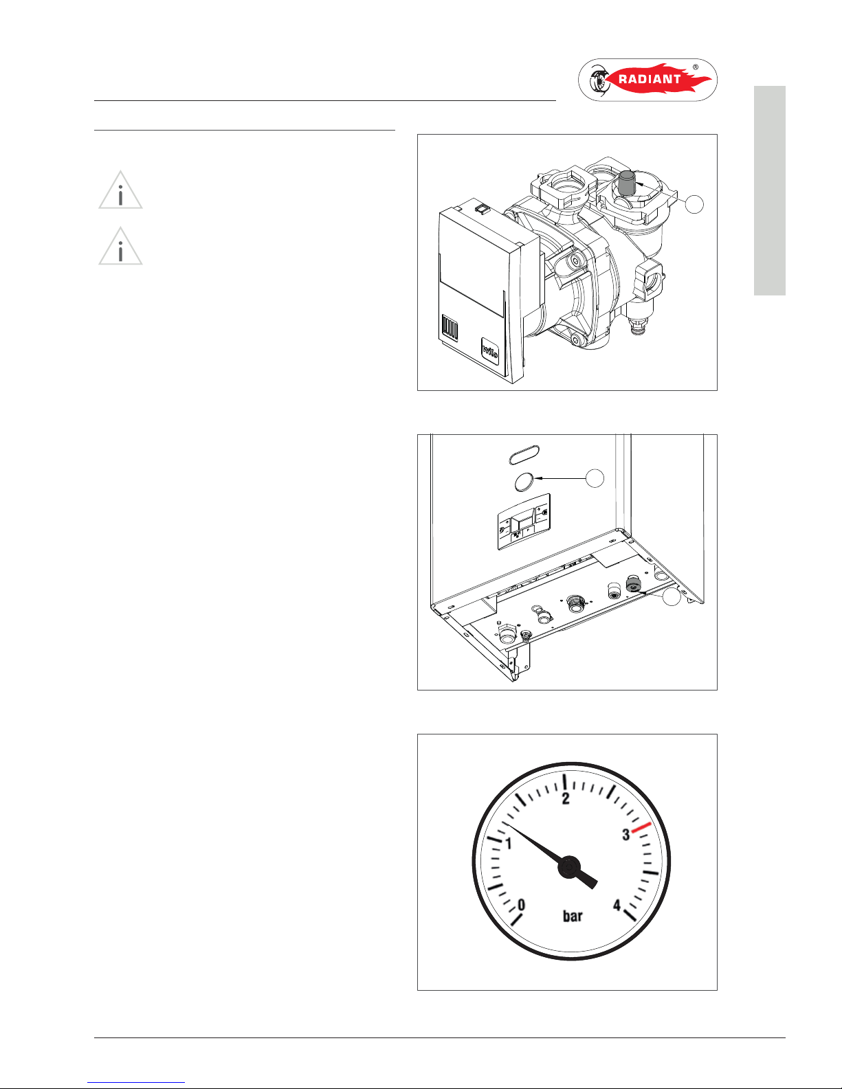
1.1.10. SYSTEM FILLING
WARNING
For system filling use only clean tap water.
WARNING
If the system is filled by adding ethylene
glycol-type chemical agents you have to install on
the loading system a hydraulic trip unit in order to
separate the heating circuit from the domestic circuit.
Before powering up the boiler, fill the system as
follows:
1. slightly loosen the cap of the circulator jolly
valve (1-fig. 1) to release the air from the
system;
2. open the feeding tap “R” (fig. 2);
3. use pressure gauge “M” (fig. 2) to make sure
that the system pressure reaches 1.2 bar (fig.
3);
4. After performing this operation, make sure that
the loading tap “R” (fig. 2) is properly closed.
5. open the air relief valves of the radiators and
check the air removal process. When the water
starts to leak close the radiators air relief
valves.
6. if after performing these operations you
observe a decrease of the water pressure
inside the system, open once again the loading
tap “R” until the pressure gauge indicates the
value of 1.2 bar (fig. 3)
1
M
R
fig. 1
fig. 2
fig. 3
Page 16

16
RBS 24 - RAD - ING - Manual - 1709.1_MIAB2013_R7
1 Protezione antigelo_firm.L181D_EN
1. INSTALLATION
INSTALLER
1.1.11. ANTI-FREEZE PROTECTION
The boiler is protected against freezing thanks to
the electronic board preparation with functions
that start the burner and heat the concerned parts
when their temperature goes below the minimum
pre-set values, protecting the boiler up to an
external temperature of -10 °C.
The device starts when the hot water temperature
goes below 5 °C, automatically starting the burner
until the water reaches the temperature of 30 °C.
The system starts even if on the display appears
“OFF”, as long as the boiler is connected to the
power (230 V) and gas supply.
For long periods of standby, please empty the boiler
and the plant.
If the temperature goes below -10° centigrades,
please fill the plant with anti-freeze liquid
(CLEANPASS FLUIDO AG cod. 98716LA) and insert
and electrical resistances kit (cod. 82259LP).
DILUTION PERCENTAGE OF CLEANPASS
FLUIDO AG
ANTIFREEZE ETHYLENE GLYCOL
TEMPERATURE
FREEZING POINT
(%) VOLUME (°C)
20 -7.5
30 -13
35 -18
40 - 22.5
45 -28
50 -33.5
55 -42
60 -50
RECOMMENDED MINIMUM PERCENTAGE OF
GLYCOL : 20 %
Page 17
17
RBS 24 - RAD - ING - Manual - 1709.1_MIAB2013_R7
1 Allacciamento gas_elettrico_MIAB_EN
1. INSTALLATION
INSTALLER
1.1.12. GAS CONNECTION
DANGER
In order to connect the gas connector of
the boiler to the supply pipe use a stop seal of an
appropriate size and material. The use of hemp,
teflon tape or similar materials is strictly forbidden.
BEFORE PERFORMING THE GAS CONNECTION,
MAKE SURE THAT:
› the gas adduction line complies with the
standards and regulations in force;
› the tubing's section suits the requested capacity
and its length;
› the tubing is equipped with all safety and control
devices required by the standards in force;
› the internal and external seals of the gas infeed
plant are checked;
› the device is suitable for use with the type of
gas available by checking the boiler data plate
(placed on the inner side of the front casing. If
they do not match you must take the necessary
measures to adapt the boiler to another type of
gas (see chapter GAS TRANSFORMATION);
› the gas supply pressure falls within the values
indicated on the data plate.
1.1.13. ELECTRICAL CONNECTION
DANGER
The equipment is electrically safe only
if it is properly connected to an efficient grounding
system, performed in compliance with the safety
standards in force. You should check this essential
safety requirement. If in doubt, request an accurate
check of the electrical system performed by qualified
staff, as the manufacturer is not responsible for any
damages caused by lack of grounding system.
› Make sure that the electrical systems is suitable
for the maximum power absorbed by the
equipment, value indicated on the data plate.
› make sure that the cables section is appropriate
for the maximum power absorbed by the
equipment and that it is however not lower than
1 mm
2
.
› The equipment works with alternating current of
230 V and 50 Hz.
WARNING
Make sure that the phase and neutral
cables connection is performed in compliance with
the wiring diagram (see chapter WIRING DIAGRAM).
WARNING
It is strictly forbidden the use of adaptors,
multiple plugs and/or extensions for the general
power supply of the equipment from the electrical
network.
Page 18
18
RBS 24 - RAD - ING - Manual - 1709.1_MIAB2013_R7
1 Collegamenti elettrici opzionali_MIAB2013_EN
1. INSTALLATION
INSTALLER
1.1.14. OPTIONAL ELECTRICAL
CONNECTIONS
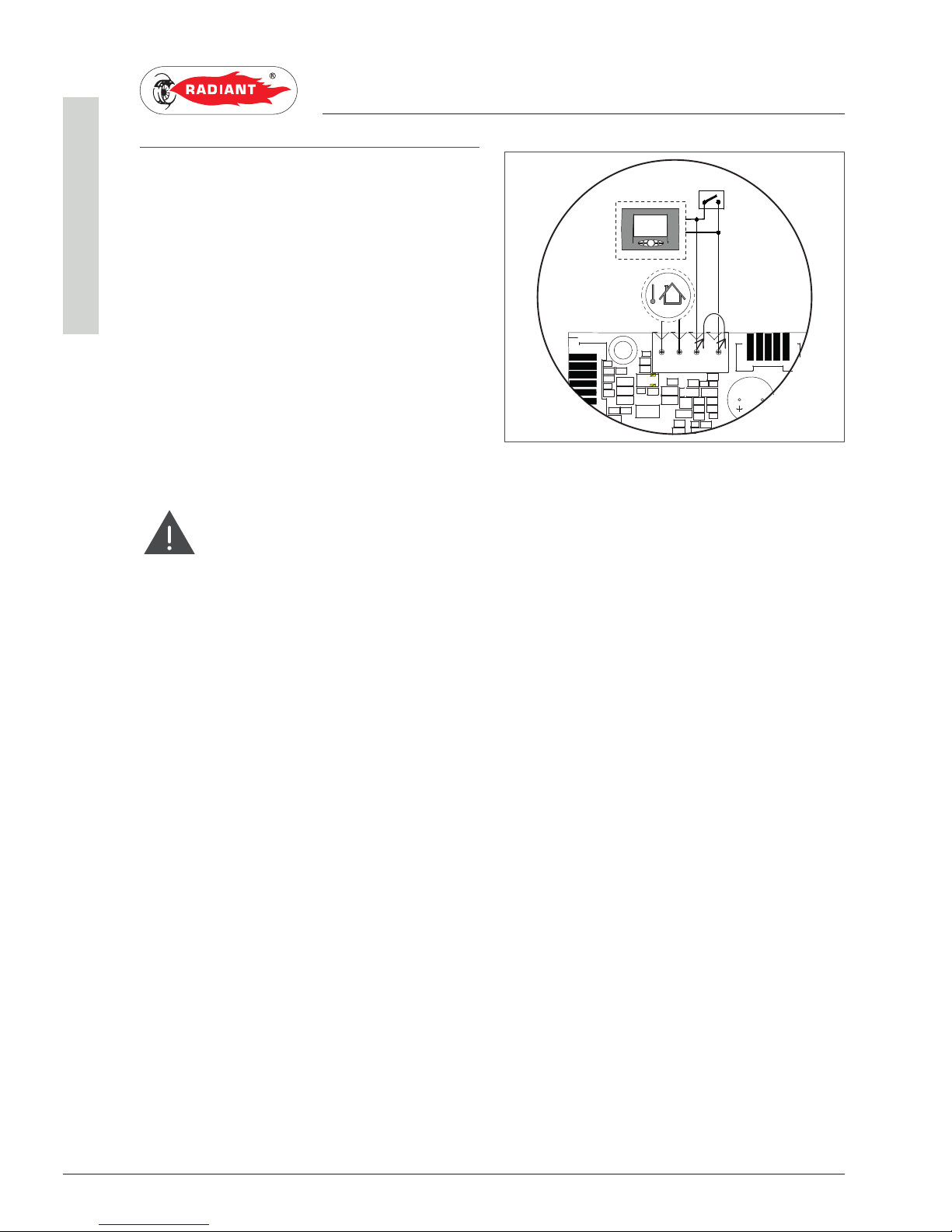
To wire the optionals below:
• (EP) EXTERNAL TEMPERATURE PROBE CODE
73518LA
• (ET) ENVIRONMENT THERMOSTAT
• (CR) REMOTE CONTROL OPEN THERM CODE 40-
00017
use the terminal placed inside the control panel as
follows:
DANGER
Cut off the voltage from the main switch.
› remove the boiler's front casing (refer to chapter
ACCESSING THE BOILER).
› remove the crankcase of the control panel (see
chapter ACCESSING THE ELECTRONIC BOARD).
· For the external temperature Probe connect
the two non-polarised conductors to the
M0904 contacts (see 'SE' fig. 1).
· For the ambient thermostat or Remote
Control, first remove the bridge on the M0904
terminal board and then connect the two
non-polarised conductors of the ambient
thermostat or remote control (see 'TA' or 'CR'
fig. 1).
After performing these operations, remount the
crankcase of the control panel and then re-fit the
front casing.
SE
TA
CR
BUZ1000
M0902
M0904
M0900
A
2
3
4
1
fig. 1
Page 19
19
RBS 24 - RAD - ING - Manual - 1709.1_MIAB2013_R7
1 Raccordi fumari_camera aperta_EN
1. INSTALLATION
INSTALLER
1.1.15. FUME EXHAUST FITTINGS
WARNING
In order to ensure proper operation and
efficiency of the device you have to connect the boiler
fume exhaust fitting to the fume exhaust duct using
appropriate flue fittings for traditional boilers. We
recommend installing approved discharge systems
approved by approved by RADIANT.
WARNING
You cannot use traditional flue fittings for
the discharge ducts of the condensing boilers, nor
vice versa.
› In order to discharge the fumes through a fumes
exhaust duct carefully follow the technical
standards in force.
› Suction and discharge systems, tailored to
individual installations, must be protected with
accessories that prevent the ingress of foreign
objects and atmospheric agents.
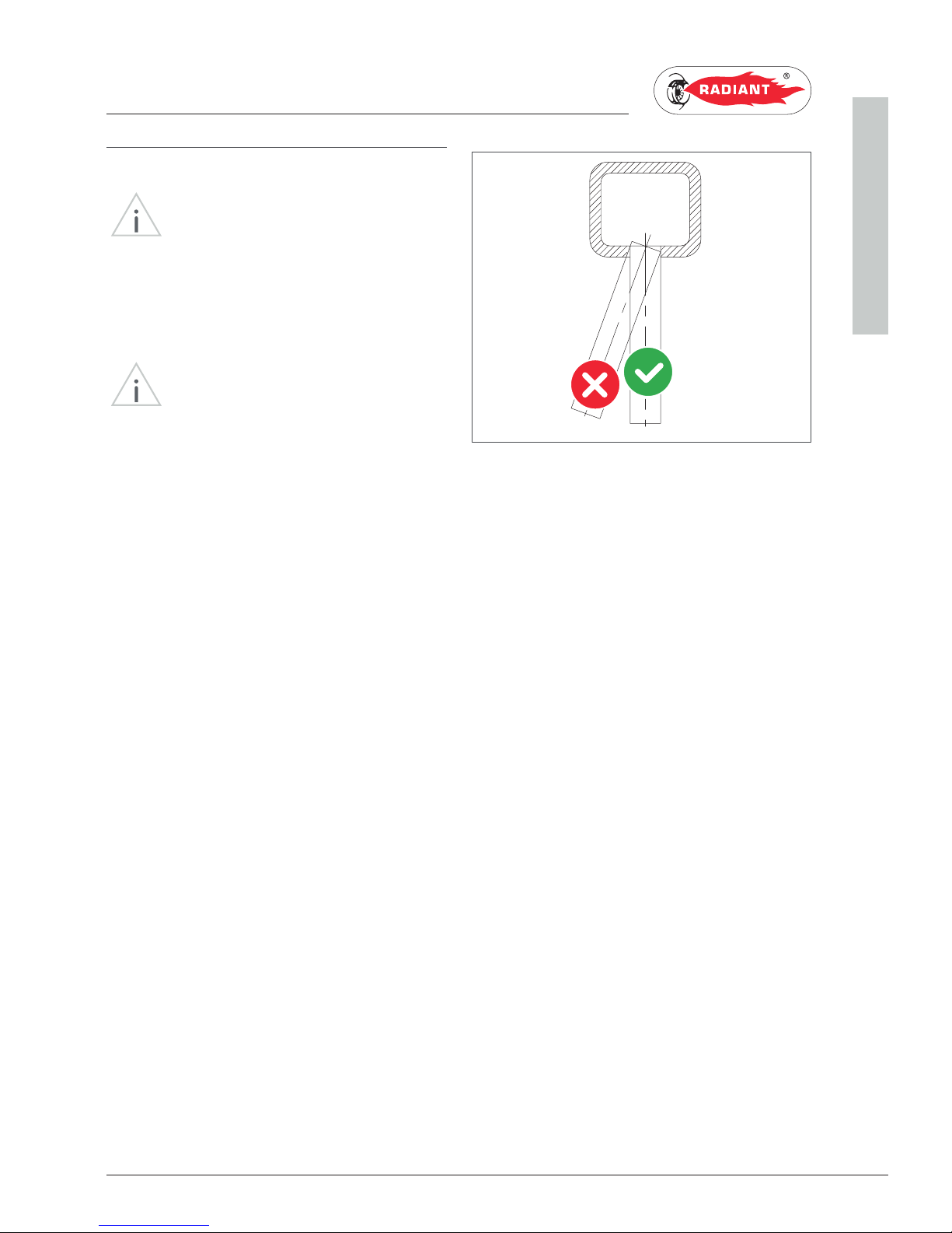
› Make sure that the discharge tube doe not
protrude inside the fumes exhaust duct, stop
before it reaches the inner surface of the latter.
› The discharge duct must be perpendicular with
the opposite internal wall of the chimney or of
the fumes exhaust duct (fig. 1).
fig. 1
Page 20
20
RBS 24 - RAD - ING - Manual - 1709.1_MIAB2013_R7
1 Tipologie di installazione_B11BS_EN
1. INSTALLATION
INSTALLER
1.1.16. TYPES OF INSTALLATION
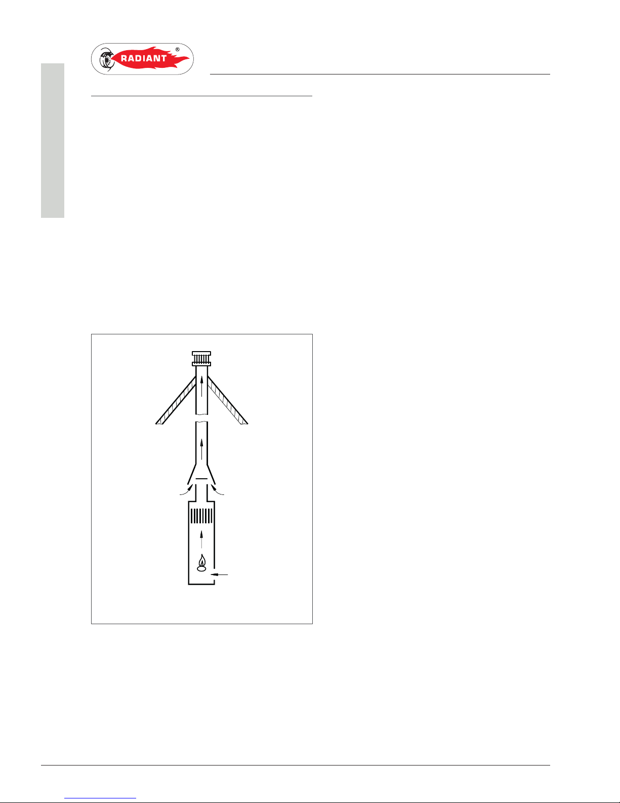
For this type of boiler are available the following
fumes discharge configurations: B11BS (see Fig. 1).
› B11BS:
· Type B, open chamber boiler, equipped with a
control device for the evacuation of combustion
products (flue safety thermostat).
· Air intake in the environment and flues
exhaust to the outside.
· For the minimum chimney height allowed,
refer to the ‘TECHNICAL DATA’ paragraph.
DISCHARGE OF COMBUSTION PRODUCTS FOR
B-TYPE DEVICES.
The gas devices, provided with connection for
fumes exhaust tube, must be directly connected to
efficient chimneys or fume exhaust ducts: only if
these are missing you can discharge the combustion
products directly through the gas devices.
The connection to the chimney or to the fume
exhaust ducts must respect the following
requirements:
· Be sealed and realised in materials suitable
to resist normal mechanical stress, heat,
the action of combustion products and any
condensate forming;
· have no more than three changes in direction,
including the chimney and/or fume exhaust
duct inlet connection, made with internal
angles greater than 90°. The changes in
direction must be made only by using curved
curved elements;
· have the axis of the inlet end perpendicular to
the internal wall opposite to the chimney or
fume exhaust duct;
· have, along its entire length, a section equal
to or greater then that of the connection of the
device discharge tube;
· have no shut-off devices (shutters).
· for direct external discharge there must be no
more than two changes in direction.
LOCATIONS VENTING FOR B-TYPE DEVICES
The locations in which are installed gas devices
must be vented so as to ensure the amount of air
necessary for a regular combustion and for location
ventilation. The natural air intake must take place
directly through:
B11BS
fig. 1
Page 21

21
RBS 24 - RAD - ING - Manual - 1709.1_MIAB2013_R7
1 Tipologie di installazione_B11BS_EN
1. INSTALLATION
INSTALLER
· permanent openings on the external walls of
the location (windows);
· single or collective, ramified ventilation ducts.
The openings on the external walls of the location
must respect the following requirements:
· have a net overall free passage section of
at least 6 cm
2
for every kW of heat capacity
installed with a minimum of 100 cm
2
;
· they must be realized so as to make sure that
the opening inlets are not obstructed (neither
indoors nor outdoors);
· they must be protected with grids, metal
meshes, etc. so as to keep the useful section
mentioned above.
· they must be placed at a height next to the
floor level such as to allow proper operation of
the combustion products discharge systems;
if such position can not be obtained, please
increase by at least 50% the section of the
vents.
Page 22

Page 23

All operations described below relative to first start-
up, maintenance and replacement should be performed
only by qualified personnel and authorized by RADIANT
BRUCIATORI S.p.A.
1. SUPPORT CENTRE SECTION2. SUPPORT CENTER SECTION
Page 24

24
RBS 24 - RAD - ING - Manual - 1709.1_MIAB2013_R7
2 Operazioni preliminari per la prima acc_EN
2. FIRST START-UP
SUPPORT CENTRE
2.1. FIRST START-UP
2.1.1. PRELIMINARY OPERATIONS
FOR FIRST START-UP
The first start-up operations consist in checking
the correct installation, adjustment and operation
of the device. Proceed as follows:
› check the inner system sealing in accordance
with the indications provided by standard and
regulations in forced;
› check if the gas used is suitable for the boiler;
› check if the gas capacity and relative pressures
comply with those on the plate;
› check the intervention of the safety device in
case of lack of gas;
› make sure that the device supply voltage
corresponds with that on the plate (230 V – 50
Hz) and that the wiring is correct;
› make sure that the grounding system works
properly;
› make sure that the combustion air adduction
and fumes and condensate discharge take
place properly in compliance with the Local and
National Laws and Standards in force;
› make sure that the fumes discharge tube and its
connection to the fume exhaust duct comply with
the requirements of the Local and National Laws
and Standards;
› make sure that the heating system gate valves
are open;
› make sure that there is no intake of gaseous
products within the system;
› make sure that there are no flammable liquids
or materials near the device;
› open the boiler gas tap and make sure that there
are no gas leaks upstream from the device (the
burner gas connection must be checked while
the machine is running);
› in case of new installation of the gas supply
network, the air inside the tubes may block the
device at its first start-up. You might have to
repeat the start-up procedure to purge all the air
inside the tube.
Page 25

25
RBS 24 - RAD - ING - Manual - 1709.1_MIAB2013_R7
2 Messa in funzione della caldaia_solo risc_bitermica_MIAB2013_EN
2. FIRST START-UP
SUPPORT CENTRE
2.1.2. BOILER COMMISSIONING
WARNING
Make sure that the system is correctly
filled.
Proceed with boiler commissioning as follows:
› Power the boiler.
› Open the gas tap.
› Use the ‘
’ button to select the HEATING
ONLY operation mode. With the '
' symbol
displayed and a static signal on the display, the
function is activated.
› The burner will start as soon as the thermostat
contact is closed;
› if the flame is missing the board will repeat the
start-up operations after post-ventilation (30
seconds).
› You might have to repeat the start-up operation
several times to release all air inside the gas
tube. Before repeating the operation, wait at
least 5 seconds from the last start-up attempt
and unlock the boiler from “E01” error code by
pressing the Reset ‘
’ key.
Page 26
26
RBS 24 - RAD - ING - Manual - 1709.1_MIAB2013_R7
2 Verifica e taratura delle pressioni gas_combinata_MIAB2013_EN
2. FIRST START-UP
SUPPORT CENTRE
2.1.3. GAS PRESSURE CHECK AND
CALIBRATION
In order to check and calibrate the minimum and
maximum gas pressures, proceed as follows:
› remove the boiler's front casing (refer to chapter
ACCESSING THE BOILER);
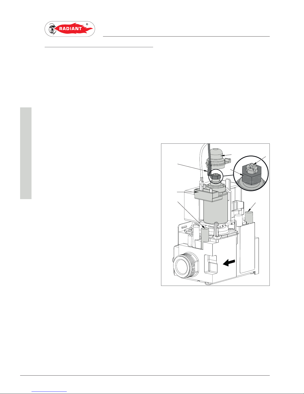
› loosen the screws in the gas 'B' discharge socket
(fig. 1) and insert the manometer.
FOR MAXIMUM DOMESTIC HEATING POWER
USING METHANE
› Set the maximum domestic water temperature;
› turn on a domestic hot water tap as far as it
will go and check that the gas pressure on the
manometer is compliant with the data indicated
in the "TECHNICAL DATA" chapter;
› If not, remove the cap 'A' (fig. 1) and using a
10mm wrench, rotate nut 'C' (fig. 1) until the
manometer indicates the correct pressure.
FOR MAXIMUM DOMESTIC HEATING POWER
USING LPG
› Remove cap 'A' (fig. 1) from the modulator and
check that nut 'C' (fig. 1) is tightened completely.
› turn on a domestic hot water tap as far as it
will go and check that the gas pressure on the
manometer is compliant with the data indicated
in the "TECHNICAL DATA" chapter;
› If not, adjust the mains supply pressure regulator
until the manometer displays the correct
pressure (if using mixed gas G30 - G31, regulate
the input pressure of G31).
FOR MINIMUM DOMESTIC HEATING POWER
› Disconnect one of the two supply Fastons 'F'
(fig. 1) on the modulator 'E' (fig. 1) and check the
gas pressure on the manometer complies with
the data indicated in the "TECHNICAL DATA"
chapter;
› If not, keep nut 'C' in place with an open 10
mm wrench, and use a flat headed screwdriver
to rotate screw 'D' (fig. 1) until the manometer
indicates the correct pressure.
› reconnect the supply Fastom to the modulator
'E' (fig. 1);
› re-fit cap 'A' (fig. 1) to the modulator in the
original position for correct operation.
KEY:
A- CAP
B- GAS OUTPUT PRESSURE SOCKET
C- MAXIMUM ADJUSTMENT NUT
D- MINIMUM ADJUSTMENT SCREW
E- MODULATOR
F- FASTON
G- GAS INPUT PRESSURE SOCKET
B
A
E
F
G
D
C
fig. 1
Page 27
27
RBS 24 - RAD - ING - Manual - 1709.1_MIAB2013_R7
2 Verifica e taratura delle pressioni gas_combinata_MIAB2013_EN
2. FIRST START-UP
SUPPORT CENTRE
TO ADJUST THE MINIMUM C.H. FIRE RATING
WARNING
Only continue after having calibrated the
domestic minimum power pressure.
› Access parameter 'P13' by following the
procedure indicated in the "ACCESSING AND
PROGRAMMING THE PARAMETERS" chapter
and check the gas pressure on the manometer
complies with the data indicated in the
"TECHNICAL DATA" chapter;
› If not, use the '
' and ' ' keys on the domestic
heating
to change the parameter values,
expressed as a percentage, which corresponds
proportionally to the pressure indicated on the
manometer.
› Keep the '
' button pressed until the 'P01'
parameter is displayed in order to confirm the
modified value.
› Once adjustment is complete, quit the
parameters menu by pressing the '
' key. The
display will show 'OFF';
› close the gas tap, remove the manometer from
the gas valve pressure socket and tighten the
screws;
› open the gas tap, switch the boiler on and check
for any gas leaks.
TO ADJUST THE MAXIMUM C.H. FIRE RATING
› Access parameter ‘P01’ by following the
procedure indicated in the “ACCESSING AND
PROGRAMMING THE PARAMETERS” chapter
and check the matching gas pressure and
nominal firing rate required for the installation,
as per the chapter “DIAGRAM NOMINAL FIRE
RATE/GAS PRESSURES”.
› Use the ‘
’ and ‘ ’ keys on the domestic
heating
to change the parameter values,
expressed as a percentage, which corresponds
proportionally to the pressure indicated on the
manometer.
› Keep the ‘
’ button pressed until the ‘P01’
parameter is displayed in order to confirm the
modified value.
› Once adjustment is complete, quit the
parameters menu by pressing the ‘
’ key. The
display will show ‘OFF’;
› close the gas tap, remove the manometer from
the gas valve pressure socket and tighten the
screws;
› open the gas tap, switch the boiler on and check
for any gas leaks.
Page 28
28
RBS 24 - RAD - ING - Manual - 1709.1_MIAB2013_R7
2 Accesso e programmazione dei parametri_MIAB_R7_EN
2. FIRST START-UP
SUPPORT CENTRE
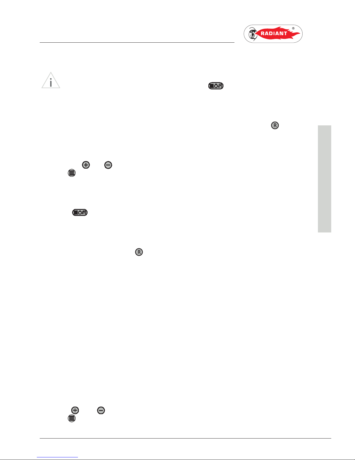
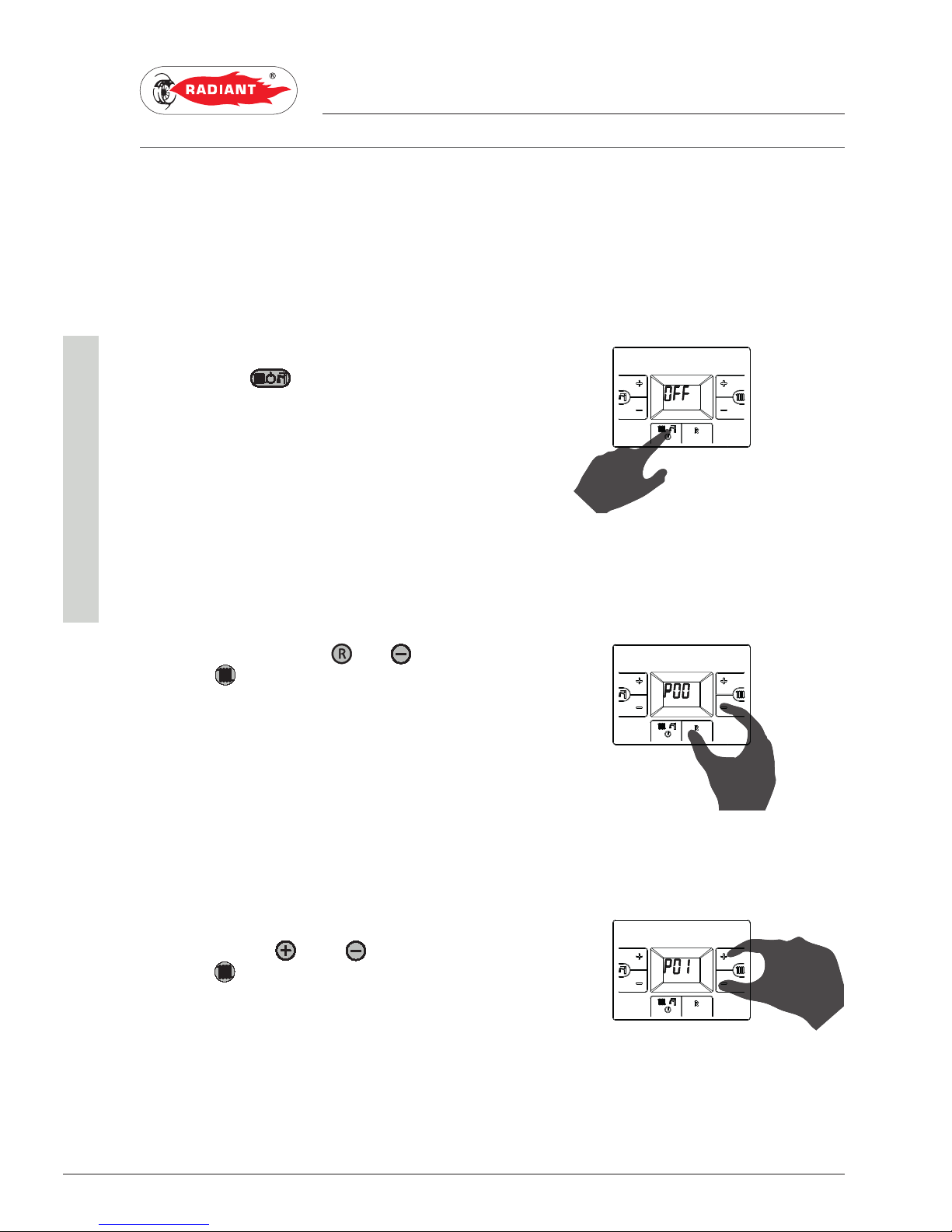
2.1.4. ACCESSING AND PROGRAMMING THE PARAMETERS
To access the parameters menu and adjust their values, follow the procedure below:
1. Press the "
" button to select the OFF
mode.
2. Press and hold both the '
' and ' ' domestic
circuit
buttons and wait for 'P00' to appear
on the display, then release the buttons.
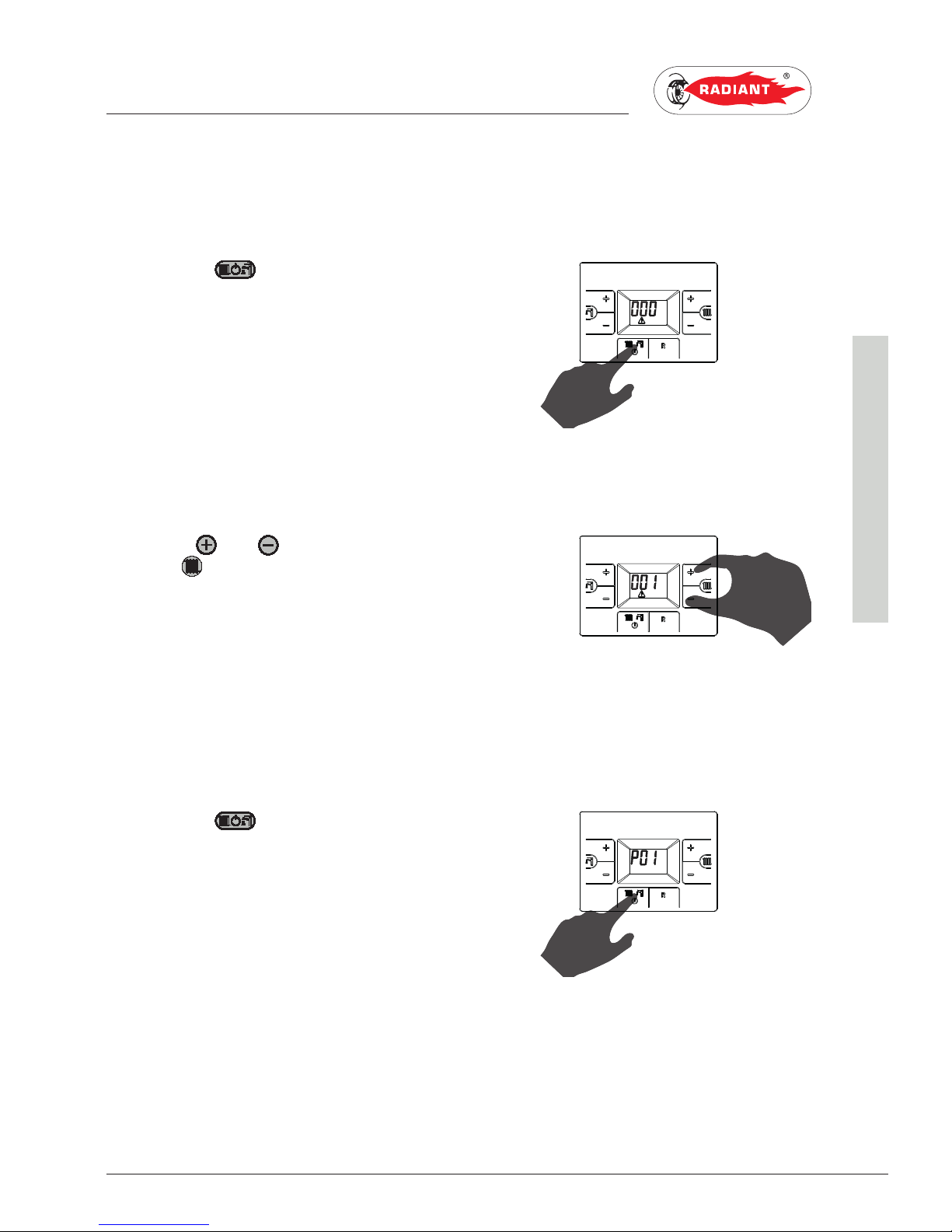
3. Use the keys ‘
’ and ‘ ’ of the heating
circuit
to select the parameter to be edited.
Page 29
29
RBS 24 - RAD - ING - Manual - 1709.1_MIAB2013_R7
2 Accesso e programmazione dei parametri_MIAB_R7_EN
2. FIRST START-UP
SUPPORT CENTRE
4. Keep the ' ' button pressed until the
parameter value is displayed.
5. Use the ‘
’ and ‘ ’ buttons of the domestic
circuit
to change the parameter value.
6. Keep the '
' button pressed until the
parameter is displayed in order to confirm the
modified value.
Page 30
30
RBS 24 - RAD - ING - Manual - 1709.1_MIAB2013_R7
2 Accesso e programmazione dei parametri_MIAB_R7_EN
2. FIRST START-UP
SUPPORT CENTRE
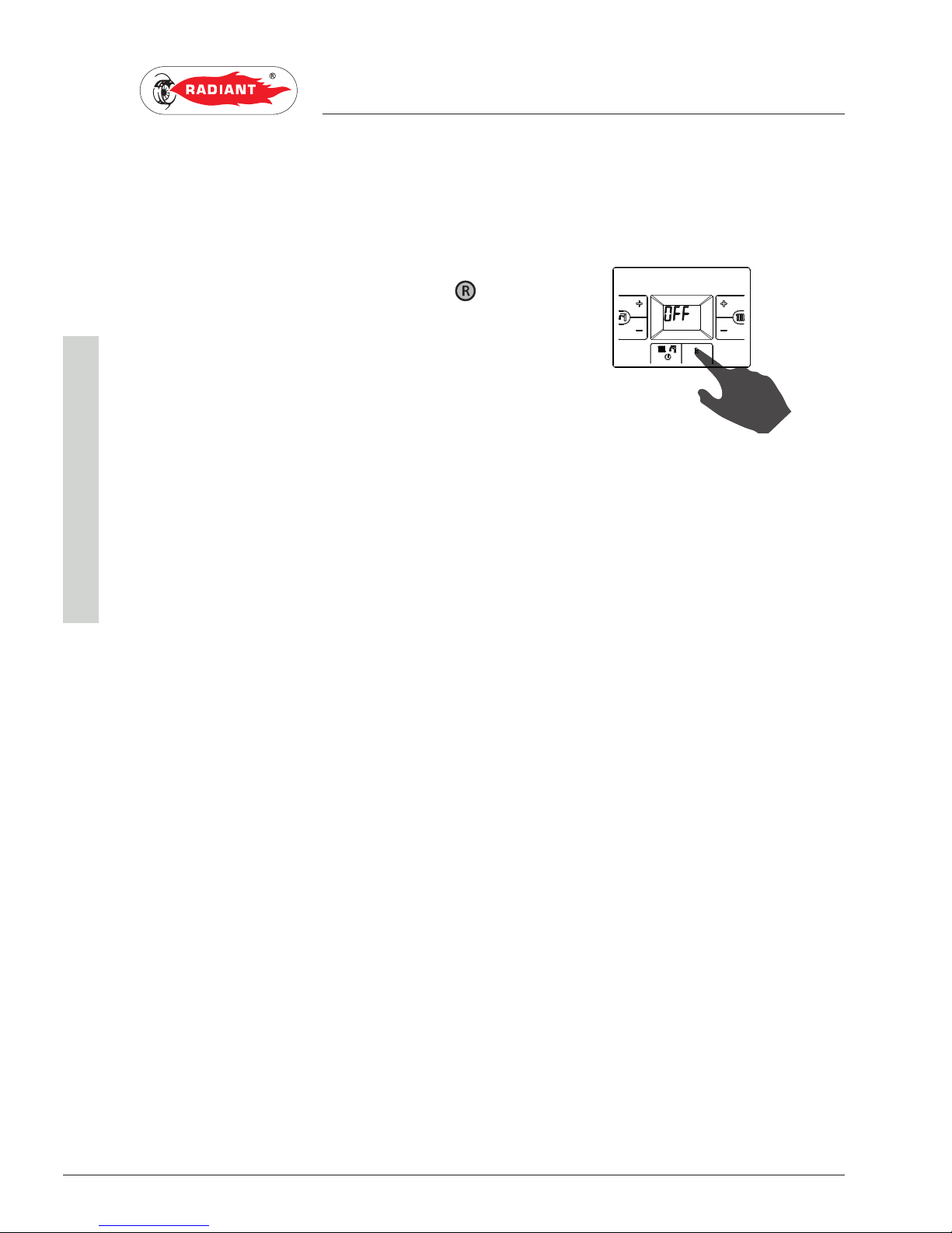
7. To quit the parameters menu, press the ' '
button until 'OFF' is displayed.
Page 31

31
RBS 24 - RAD - ING - Manual - 1709.1_MIAB2013_R7
2 Tabella parametri_MIAB2013_firm.H070C_EN
2. FIRST START-UP
SUPPORT CENTRE
2.1.5. PARAMETER TABLE MIAB2013
PARAMETER DESCRIPTION RANGE FUNCTION
P00 GAS TYPE SELECTION
ATTENTION:
READ THE INSTRUCTION IN CHAPTER ‘GAS
TRANSFORMATION’ BEFORE CHANGING THIS
PARAMETER.
000 - 001 000 = METHANE
001 = LPG
P01 ADJUSTMENT OF MAXIMUM HEATING POWER
THIS PARAMETER IS USED TO SET THE MAXIMUM
BURNER GAS PRESSURE WHEN HEATING.
TO SET THE VALUE, FOLLOW THE INSTRUCTIONS
IN THE 'GAS PRESSURE CHECK AND CALIBRATION'
CHAPTER.
000 - 100 THE VALUE IS EXPRESSED IN PERCENTAGE
(PRE-SET TO 100)
P02 STARTING STEP ADJUSTMENT
THIS PARAMETER IS USED TO SET THE BURNER GAS
PRESSURE WHEN THE BOILER IS IN THE IGNITION
PHASE.
000 - 100 THE VALUE IS EXPRESSED IN PERCENTAGE
(PRE-SET TO 40)
P03 HEATING TIMING
THROUGH THIS PARAMETER YOU CAN SET THE
MINIMUM TIME FOR WHICH THE BURNER WILL BE
TURNED OFF ONCE THE HEATING TEMPERATURE
REACHED THE USER SET TEMPERATURE.
000 - 090 VALUE EXPRESSED IN MULTIPLES OF 5
SECONDS
(PRE-SET AT 36 X 5 = 180 SECONDS)
P04 HEATING RUN-UP
THROUGH THIS PARAMETER YOU CAN SET THE TIME,
DURING START-UP PHASE, NECESSARY FOR THE
BOILER TO REACH THE MAXIMUM SET POWER IN
HEATING.
000 - 010 THE VALUE IS EXPRESSED IN MINUTES
(PRE-SET TO 1 MINUTE)
P05 POST-CIRCULATION HEATING TIMING
THROUGH THIS PARAMETER YOU CAN SET THE PUMP
DURATION OF OPERATION DURING HEATING CYCLE,
AFTER THE MAIN BURNER TURNS OFF DUE TO THE
ENVIRONMENT THERMOSTAT.
000 - 090 VALUE EXPRESSED IN MULTIPLES OF 5
SECONDS
(PRE-SET AT 36 X 5 = 180 SECONDS)
P06 POST-CIRCULATION DOMESTIC HEATING TIMING
(NOT APPLICABLE TO BI-THERMAL BOILERS)
THROUGH THIS PARAMETER YOU CAN SET THE PUMP
OPERATION DURATION ON THE DOMESTIC CIRCUIT,
AFTER THE TAP IS CLOSED.
000 - 090 VALUE EXPRESSED IN MULTIPLES OF 5
SECONDS
(PRE-SET AT 18 X 5 = 90 SECONDS)
Page 32
32
RBS 24 - RAD - ING - Manual - 1709.1_MIAB2013_R7
2 Tabella parametri_MIAB2013_firm.H070C_EN
2. FIRST START-UP
SUPPORT CENTRE
PARAMETER DESCRIPTION RANGE FUNCTION
P07 ANTI-WATER HAMMER SELECTION
BY ACTIVATING THIS FUNCTION, THE DOMESTIC
CONTACT IS DELAYED FOR A TIME EQUAL TO THAT
SET.
000 - 003 000 = DISABLED
THE VALUE IS EXPRESSED IN SECONDS
(PRE-SET TO 2 SECONDS)
P08 HEATING START DELAY
USING THIS SETTING, THE BOILER START DELAY
TIME CAN BE SET, IN HEATING PHASE, WHEN THE
AMBIENT THERMOSTAT CONTACT IS CLOSED.
000-199 000 = DISABLED (PRE-SET BY DEFAULT)
THE VALUE IS EXPRESSED IN SECONDS
P09 SETTING THE HEATING TEMPERATURE
IN CASE OF DIRECT SUPPLY, BY A GENERATOR, OF A
LOW TEMPERATURE SYSTEM, INSTALL A SECURITY
THERMOSTAT ON THE DELIVERY WHICH INTERRUPTS
THE OPERATION OF THE GENERATOR IN CASE OF
HIGH DELIVERY TEMPERATURE. THE COMPANY IS
NOT HELD LIABLE FOR RESULTING DAMAGES TO
PERSONS OR THINGS DUE TO THE NON-OBSERVANCE
OF SUCH INDICATION.
000 - 001 000 = STANDARD (30-80 °C)
(SET BY DEFAULT)
001 = REDUCED (25-45 °C) FOR FLOOR
SYSTEMS
P10 POST-VENTILATION TIMER
THIS PARAMETER SETS HOW LONG THE FAN
OPERATES AFTER THE BURNER HAS SWITCHED OFF.
003-200 VALUE EXPRESSED IN MULTIPLES OF 3
SECONDS
(PRE-SET TO 4×3=12 SECONDS)
P11 BOILER TYPE SELECTION 000 - 003 000 = BITHERMAL
001 = MONOTHERMAL INSTANT
002 = HEATING ONLY
003 = ACCUMULATION
Page 33

33
RBS 24 - RAD - ING - Manual - 1709.1_MIAB2013_R7
2 Tabella parametri_MIAB2013_firm.H070C_EN
2. FIRST START-UP
SUPPORT CENTRE
PARAMETER DESCRIPTION RANGE FUNCTION
P12 CLIMATE COMPENSATION CURVE
(ONLY WITH EXTERNAL PROBE CONNECTED)
YOU CAN CONNECT AN EXTERNAL TEMPERATURE
PROBE (SEE CHAPTER ‘ELECTRICAL CONNECTIONS’)
THAT AUTOMATICALLY CHANGES THE DELIVERY
TEMPERATURE BASED ON THE EXTERNAL MEASURED
TEMPERATURE. THE NATURE OF THE CORRECTION
DEPENDS ON THE THERMO-ADJUSTMENT VALUE KD
SET (SEE CHART).
THE SELECTION OF THE CURVE IS DETERMINED BY
THE MAXIMUM DELIVERY TEMPERATURE TM AND THE
MINIMUM EXTERNAL TEMPERATURE TE TAKING INTO
ACCOUNT THE HOUSE INSULATION DEGREE.
THE VALUES OF THE DELIVERY TEMPERATURES TM,
REFER TO STANDARD SYSTEMS 30-80 °C OR FLOOR
SYSTEMS 25-45 °C. THE SYSTEM TYPE CAN BE SET
FROM PARAMETER P11.
000 - 030 (SET BY DEFAULT AT 30) THE NUMBERING OF
THE VALUE CORRESPONDS TO ‘KD’ CURVES
ON THE CHART (SEE CHART BELOW).
P13 ADJUSTMENT OF MINIMUM HEATING POWER
THIS PARAMETER IS USED TO SET THE MINIMUM
BURNER GAS PRESSURE WHEN HEATING.
TO SET THE VALUE, FOLLOW THE INSTRUCTIONS
IN THE 'GAS PRESSURE CHECK AND CALIBRATION'
CHAPTER.
000 - 100 THE VALUE IS EXPRESSED IN PERCENTAGE
Te (°C)
353025201510
75
80
45 MAX
Tm (°C)
5
0
-5
-10
65
55
60
50
40
45
35
30
30
-15-20
25
MIN
35
70
Kd = 0
Kd = 5
Kd = 10
Kd = 15
Kd = 20
Kd = 25
Kd = 30
Page 34

34
RBS 24 - RAD - ING - Manual - 1709.1_MIAB2013_R7
2 Tabella parametri_MIAB2013_firm.H070C_EN
2. FIRST START-UP
SUPPORT CENTRE
PARAMETER DESCRIPTION RANGE FUNCTION
P14 ANTI-LEGIONELLA FUNCTION
(ONLY FOR ACCUMULATION BOILERS)
THIS PARAMETER ACTIVATES/DEACTIVATES THE
"ANTI-LEGIONELLA" HEAT TREATMENT OF THE
ACCUMULATION BOILER.
FURTHERMORE, THE
DAYS AFTER WHICH THE FUNCTION IS ACTIVATED
AUTOMATICALLY CAN BE SET. THE DEFAULT VALUE IS
7 DAYS. WHEN THE FUNCTION IS ACTIVE
, THE WATER
TEMPERATURE IN THE ACCUMULATED IS BROUGHT
TO OVER 60°C WITH A POSSIBLE RISK OF SCALDING.
KEEP UNDER CONTROL SUCH DOMESTIC HOT WATER
TREATMENT (AND INFORM THE USERS) TO AVOID
UNFORESEEABLE DAMAGES TO PERSONS, ANIMALS,
PROPERTY. A THERMOSTATIC VALVE SHOULD BE
INSTALLED AT THE DOMESTIC HOT WATER OUTLET
TO AVOID ANY BURNS.
0 - 15 0 = DISABLED
1 - 15 =
DAYS AFTER WHICH THE FUNCTION IS
ACTIVATED AUTOMATICALLY.
Page 35
35
RBS 24 - RAD - ING - Manual - 1709.1_MIAB2013_R7
2 Diagramma portata termica - Pressione gas_RBC 24_NC_EN
2. FIRST START-UP
SUPPORT CENTRE
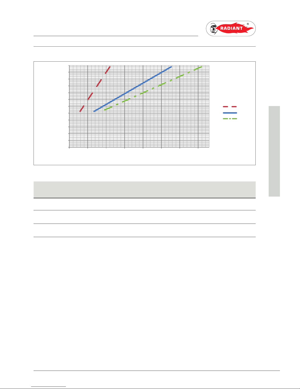
2.1.6. HEAT CAPACITY / GAS PRESSURE DIAGRAM
GAS TYPE MINIMUM GAS PRESSURE MAXIMUM GAS PRESSURE
G20 mbar 2.9 11
G30 mbar 6.7 27.7
G31 mbar 8.7 35.9
2
4
6
8
10
12
14
16
18
20
22
24
26
0 5 10 15 20 25 30 35
G20
G30
G31
HEAT CAPACITY (kW)
GAS PRESSURE (mbar)
Page 36
36
RBS 24 - RAD - ING - Manual - 1709.1_MIAB2013_R7
2 Avvertenze generali per la manutenzione_combinata_trad_EN
2. MAINTENANCE
SUPPORT CENTRE
2.2. MAINTENANCE
2.2.7. GENERAL MAINTENANCE
WARNINGS
DANGER
Before each components cleaning or
replacement operation, ALWAYS cut off the POWER,
WATER and GAS supply of the boiler.
WARNING
To ensure greater life span and proper
operation of the device, during the maintenance
operations use only original spare parts.
ATTENTION
To ensure the efficiency and safety of the
device, the maintenance operations must be realized on an
annual basis. The operations described below, are essential
to the validity of the standard RADIANT warranty and
must be performed by professionally qualified personnel
in accordance with current legislation and authorized by
RADIANT.
Please perform the following operations once a
year:
› check the sealing of the gas components, and
replace if necessary the gaskets;
› check the sealing of the water components, and
replace if necessary the gaskets;
› visually check the flame and the condition of the
combustion chamber;
› remove and clean the burner from oxidation;
› check the primary exchanger, if necessary, clean
it;
› check the max. and min. pressures as
described in the “GAS PRESSURE CHECK AND
CALIBRATION” section;
› check the operation of the gas light up and
safety systems. If necessary, remove and clean
the flame detection and light up electrodes from
incrustations paying attention to respect the
distances with respect to the burner;
› check the heating circuit safety systems: limit
temperature safety thermostat; limit pressure
safety;
› check the pre-load pressure of the expansion
vessel;
› make sure that the permanent ventilation outlets
are present, correctly sized and functioning,
based on the installed devices. Respect the
requirements provided by Local and National
legislation;
› check the integrity of the fume exhaustion
system for safety and proper operation;
› check that the wiring is performed in compliance
with the requirements in the boiler instruction
manual;
› check the wiring inside the control panel;
› check the flow and temperature of domestic hot
water.
Page 37
37
RBS 24 - RAD - ING - Manual - 1709.1_MIAB2013_R7
2 Dati tecnici_RBC 24_NC_ErP_EN
2. MAINTENANCE
SUPPORT CENTRE
2.2.8. TECHNICAL DATA
Model RBC 24
CE certification no. 0476CR0577
Gas category II2H3B/P
Discharge type type B11BS
Energy efficiency 92/42 CEE no. stars 2
Maximum nominal heat capacity in heating circuit kW 25.6
Maximum nominal heat capacity in domestic circuit kW 25.6
Minimum nominal heat capacity in heating circuit kW 12.5
Minimum nominal heat capacity in domestic circuit kW 12.5
Useful thermal power - 60/80°C kW 23.1
Minimum useful thermal power - 60/80°C kW 10.40
Performance at 100% Pn - 60/80°C % 90.2
Performance at 30% Pn - return 47°C % 88.2
Fumes temperature at nominal heat capacity °C 114
Fumes temperature at minimum heat capacity °C 93.9
Fumes mass at nominal heat capacity g/s 16.91
Fumes mass at minimum heat capacity g/s 16.47
NOx class class 2
Weighted Nox (0% O2) mg/kWh mg/kWh 156
Heating circuit
Adjustable heating temperature °C 30-80 / 25-45
Maximum operating temperature for heating circuit °C 80
Maximum operating pressure for heating circuit bar 3
Minimum operating pressure for heating circuit bar 0.3
Capacity of the system expansion vessel litres 6
Domestic circuit
Adjustable domestic temperature °C 35-60
Maximum pressure for domestic circuit bar 6
Minimum pressure for domestic circuit bar 0.5
Specific capacity in continuous service - Δt 30°C litres/min 11.07
Dimensional characteristics
Width mm 410
Depth mm 320
Height mm 730
Gross weight Kg 32
Water connections
Flow Ø 3/4”
Cold water Ø 1/2”
Hot water Ø 1/2”
Gas Ø 3/4”
Return Ø 3/4”
Fume exhaust fittings
Diameter flue terminal mm 130
Height flue terminal m 0.5
Page 38

38
RBS 24 - RAD - ING - Manual - 1709.1_MIAB2013_R7
2 Dati tecnici_RBC 24_NC_ErP_EN
2. MAINTENANCE
SUPPORT CENTRE
Electrical specifications
Voltage-frequency V/Hz 230 - 50
Max Absorbed Power W 50
Insulation rate IP X4D
Gas supply
Injectors n° 12
Nominal supply pressure - G20 mbar 20
Max. burner pressure - G20 mbar 11
Min. burner pressure - G20 mbar 2.9
Injector diameter - G20 Ø 1.3
Fuel consumption - G20 m
3
/h 2.71
Nominal Supply pressure - G30 mbar 30
Max. burner pressure - G30 mbar 27.7
Min. burner pressure - G30 mbar 6.7
Injector diameter - G30 Ø 0.77
Fuel consumption - G30 kg/h 2.02
Nominal Supply pressure - G31 mbar 37
Max. burner pressure - G31 mbar 35.9
Min. burner pressure - G31 mbar 8.7
Injector diameter - G31 Ø 0.77
Fuel consumption - G31 kg/h 1.99
Page 39

39
RBS 24 - RAD - ING - Manual - 1709.1_MIAB2013_R7
2 Dati tecnici_RBC 24_NC_ErP_EN
2. MAINTENANCE
SUPPORT CENTRE
Technical parameters for boiler space heaters, boiler combination heaters and cogeneration
space heaters
Model RBC 24
Condensing boiler [yes/no] no
Low-temperature (**) boiler: [yes/no] no
B11 boiler [yes/no] yes
Cogeneration space heater [yes/no] no
If yes, equipped with a supplementary heater [yes/no] no
Combination heater [yes/no] yes
Rated heat output Prated kW 23.10
For boiler space heaters and boiler combination
heaters: Useful heat output
At rated heat output and high-temperature regime (*) P
4
kW 23.10
At 30 % of rated heat output and low-temperature regime (**)
P
1
kW 7.68
For cogeneration space heaters: Useful heat output
At rated heat output of cogeneration space heater with
supplementary heater disabled P
CHP100+Sup0
kW -
At rated heat output of cogeneration space heater with
supplementary heater enabled P
CHP100+Sup100
kW -
)RUFRJHQHUDWLRQVSDFHKHDWHUV(OHFWULFDOHႈFLHQF\
At rated heat output of cogeneration space heater with
VXSSOHPHQWDU\KHDWHUGLVDEOHGȘ
el,CHP100+Sup0
%-
At rated heat output of cogeneration space heater with
VXSSOHPHQWDU\KHDWHUHQDEOHGȘ
el,CHP100+Sup100
%-
$X[LOLDU\HOHFWULFLW\FRQVXPSWLRQ
At full load elmax kW 0.01
At part load elmin kW 0.01
In standby mode PSB kW 0.001
6HDVRQDOVSDFHKHDWLQJHQHUJ\HႈFLHQF\Ș
s
%76
6HDVRQDOVSDFHKHDWLQJHQHUJ\HႈFLHQF\FODVV C
For boiler space heaters and boiler combination heaters:
8VHIXOHႈFLHQF\
$WUDWHGKHDWRXWSXWDQGKLJKWHPSHUDWXUHUHJLPHȘ
4
% 81.2
At 30 % of rated heat output and low-temperature regime
Ș
1
% 79.1
)RUFRJHQHUDWLRQVSDFHKHDWHUV8VHIXOHႈFLHQF\
At rated heat output of cogeneration space heater with
VXSSOHPHQWDU\KHDWHUGLVDEOHGȘ
CHP100+Sup0
%-
At rated heat output of cogeneration space heater with
VXSSOHPHQWDU\KHDWHUHQDEOHGȘ
CHP100+Sup100
%-
6XSSOHPHQWDU\KHDWHU
Rated heat output Psup kW Type of energy input 0
Other items
Standby heat loss P
stby
kW 0.2
Ignition burner power consumption P
ign
kW 0.0
Page 40

40
RBS 24 - RAD - ING - Manual - 1709.1_MIAB2013_R7
2 Dati tecnici_RBC 24_NC_ErP_EN
2. MAINTENANCE
SUPPORT CENTRE
Annual energy consumption Q
HE
kWh / GJ 27039 / 97
Sound power level, indoors L
WA
dB 52
For combination heaters:
'+:HQHUJ\HႈFLHQF\FODVV A
'HFODUHGORDGSUR¿OH L
Daily electricity consumption Q
elec
kWh 0.050
Annual electricity consumption AEC kWh 18
:DWHUKHDWLQJHQHUJ\HႈFLHQF\Ș
wh
%77
Daily fuel consumption Q
fuel
kWh 15.598
Annual fuel consumption AFC GJ 12
Contact details Tel. +39 0721 9079.1 - fax. +39 0721
9079299 - e-mail: [email protected] - http://
www.radiant.it
Name and address of the supplier RADIANT BRUCIATORI S.p.A.
Via Pantanelli, 164/166 - 61025 -
Montelabbate (PU)
(*) High-temperature regime means 60 °C return temperature at heater inlet and 80 °C feed temperature
at heater outlet.
(**) Low temperature means for condensing boilers 30 °C, for low-temperature boilers 37 °C and for
other heaters 50 °C return temperature (at heater inlet).
Page 41
41
RBS 24 - RAD - ING - Manual - 1709.1_MIAB2013_R7
2 Complessivo tecnico_RBC 24_NC_MIAB_EN
2. MAINTENANCE
SUPPORT CENTRE
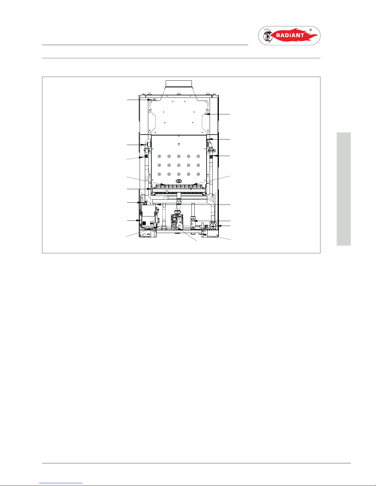
2.2.9. TECHNICAL ASSEMBLY
KEY
1. FLUE SAFETY THERMOSTAT
2. INTEGRATED HEAT EXCHANGER
3. HEATING PROBE
4. LIGHT UP ELECTRODE
5. BURNERS
6. SAFETY VALVE 3 bar
7. CIRCULATOR
8. BY-PASS
9. SMOKE HOOD
10. SAFETY THERMOSTAT
11. DOMESTIC CIRCUIT PROBE
12. DETECTION ELECTRODE
13. AIR RELIEF VALVE
14. FLOW SWITCH
15. WATER PRESSURE SWITCH
16. SYSTEM FILLING TAP
17. GAS VALVE
1
2
4
3
6
9
10
11
5
12
14
15
16
17
7
8
13
Page 42
42
RBS 24 - RAD - ING - Manual - 1709.1_MIAB2013_R7
2 Schema idraulico_RBC 24_EN
2. MAINTENANCE
SUPPORT CENTRE
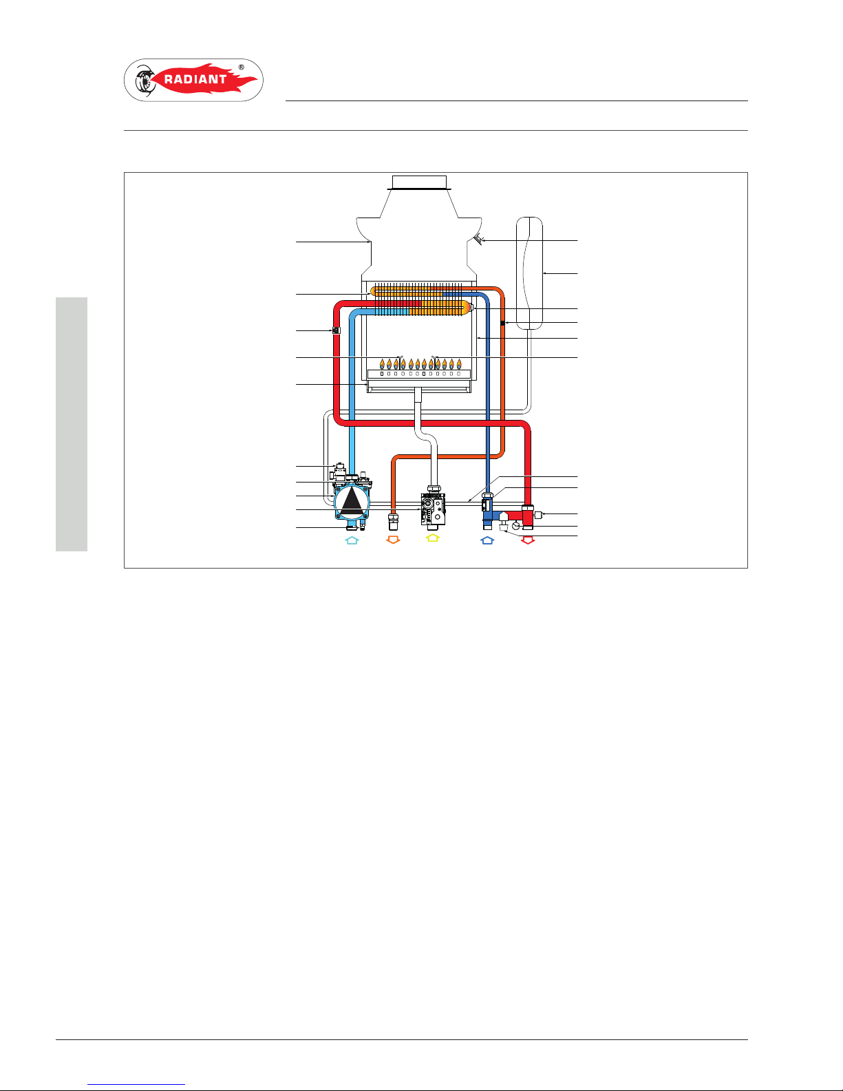
2.2.10. HYDRAULIC BOARD
KEY
R. HEATING RETURN
C. DOMESTIC HOT WATER OUTLET
G. GAS INLET
F. COLD WATER INLET
A. HEATING FORWARD
1. SMOKE HOOD
2. INTEGRATED HEAT EXCHANGER
3. HEATING PROBE
4. LIGHT UP ELECTRODE
5. BURNERS
6. SAFETY VALVE 3 bar
7. AIR RELIEF VALVE
8. CIRCULATOR
9. GAS VALVE
10. SYSTEM DRAINING TAP
11. FLUE SAFETY THERMOSTAT
12. EXPANSION TANK
13. SAFETY THERMOSTAT
14. DOMESTIC CIRCUIT PROBE
15. COMBUSTION CHAMBER
16. DETECTION ELECTRODE
17. BY-PASS
18. FLOW SWITCH
19. WATER PRESSURE SWITCH
20. MANOMETER
21. SYSTEM FILLING TAP
R
G
F
C
A
1
2
3
4
5
6
7
8
9
10
11
12
13
14
15
16
17
18
19
20
21
Page 43
43
RBS 24 - RAD - ING - Manual - 1709.1_MIAB2013_R7
2 Schema elettrico_RBC 24_HE_MIAB2013_EN
2. MAINTENANCE
SUPPORT CENTRE
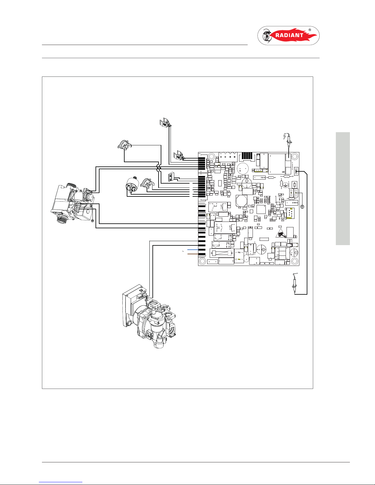
2.2.11. WIRING DIAGRAM
ER: DETECTION ELECTRODE MF: MICRO-FLOW SWITCH NE: BLACK
EA START-UP ELECTRODE SR: HEATING PROBE BI: WHITE
C: CIRCULATOR SS: DOMESTIC CIRCUIT PROBE RO: RED
VG: GAS VALVE TF: FLUE SAFETY THERMOSTAT CE: BLUE
TRA:START-UP TRANSFORMER MD: MODULATOR MA: BROWN
TS: SAFETY THERMOSTAT L: LINE
PACQ:WATER PRESSURE SWITCH N: NEUTRAL
M0104
BUZ1000
RL1200
RL0830
RL0820
R0101
M1001
L0400
C0101
F1600
T1
C0102
C0100
C0107
C0113
C0401
C0420
C0450
L0100
A
B
M0450
PD0100
~
~
PF0100
R0112
R0453
R0454
R0455
RL1201
VDR0100
B0400
B0401
VDR400
Q0420
~
~
U0130
M0103
T0420
R0100
U1000
M0902
A
M0904
M0100
M0101
M0900
A
M0901
A
P182A2
2
3
4
1
K
K
MIAB2013
ER
EA
TRA
SR
MF
220 V
50 Hz
L
N
ne
ne
C
VG
MD
ma
ce
Pacq
ro
ro
TS
ce
ma
bi
bi
SS
TF
Page 44
44
RBS 24 - RAD - ING - Manual - 1709.1_MIAB2013_R7
2 Accesso caldaia_RBC 24_R7_EN
2. MAINTENANCE
SUPPORT CENTRE
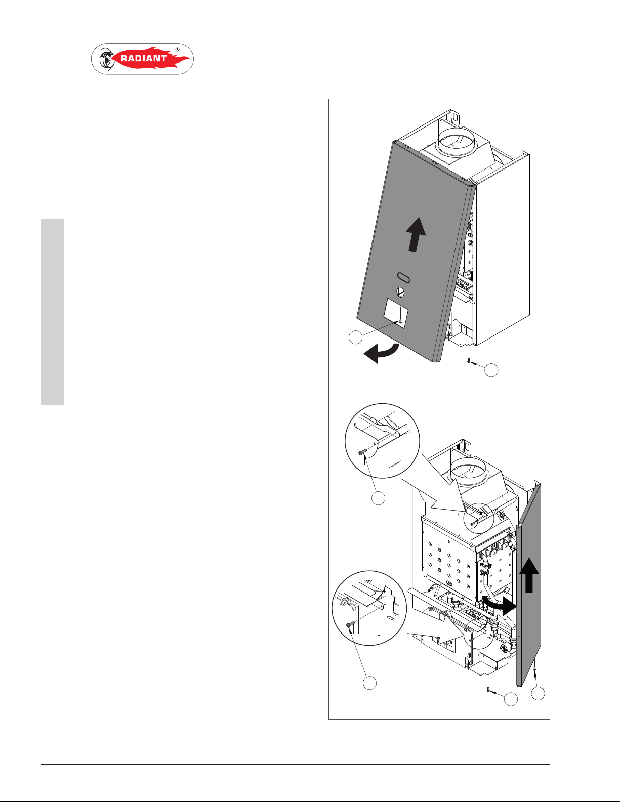
2.2.12. ACCESSING THE BOILER
For the majority of the control and maintenance
operations you have to remove one or more panels
of the casing.
The side panels can be removed only after removing
the front panel.
To intervene on the front of the boiler proceed as
follows:
› remove the fastening screws (1 - fig.1) placed on
the lower edge of the front panel;
› grab the front panel from the bottom and remove
it pulling it to yourself and then upwards (see
fig. 1).
To intervene on the side panels of the boiler proceed
as follows:
› remove the fastening screws (2 - fig.1) placed on
the front edge of the side panel;
› remove the fastening screws (3 - fig.1) placed on
the lower edge of the side panel;
› grab the bottom of the panel and remove it by
moving it sideways and then pulling it upwards
(see fig. 1).
2
3
3
1
1
2
fig. 1
Page 45
45
RBS 24 - RAD - ING - Manual - 1709.1_MIAB2013_R7
2 Accesso alla scheda elettronica_MIAB_R7_EN
2. MAINTENANCE
SUPPORT CENTRE
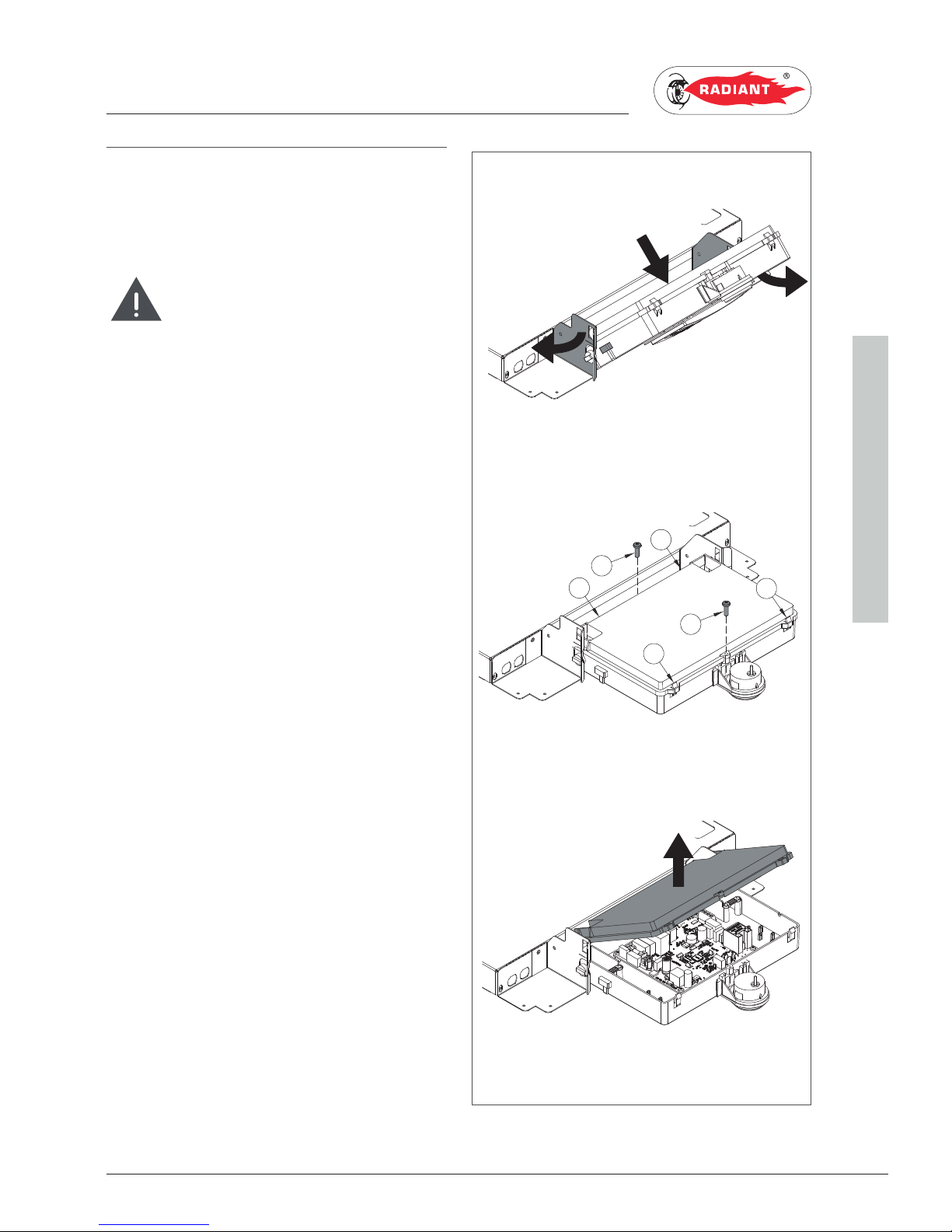
2.2.2. ACCESSING THE ELECTRONIC
BOARD
In order ot intervene on the wirings of the control
panel, please proceed as follows:
DANGER
Cut off the voltage from the main switch.
› Grab at the same time the support brackets of
the control panel (fig. 1) loosening them and turn
the panel downwards;
› unscrew the two fastening screws 1 - fig. 1;
› disengage the four hooks ‘2’ - fig. 1;
› remove the crankcase pulling it upwards.
1
2
2
2
1
2
fig. 1
Page 46
46
RBS 24 - RAD - ING - Manual - 1709.1_MIAB2013_R7
2 Svuotamento dell'impianto_RBS_R7_EN
2. MAINTENANCE
SUPPORT CENTRE
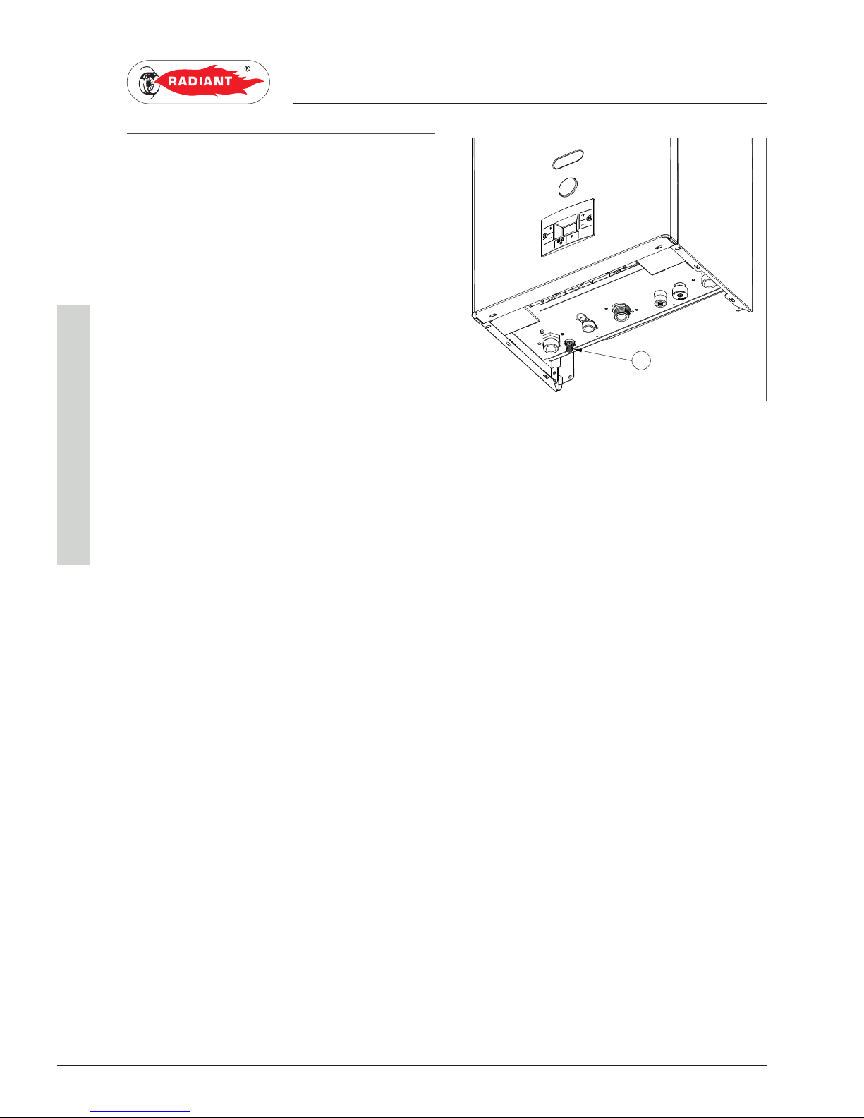
2.2.14. SYSTEM EMPTYING
HEATING SYSTEM EMPTYING
Whenever you need to empty the system, proceed
as follows:
› switch the boiler to “WINTER” mode and activate
it;
› turn off the main power supply switch;
› wait for the boiler to cool down;
› connect a flexible tube to the system emptying
outlet tap 'RS' (fig. 1) and connect the other end
of the tube to a suitable discharge;
› turn the discharge tap of the system ‘RS’ (fig. 1);
› open the relief valves of the radiators starting
from the one at the top and continuing
downwards;
› after draining out all water, close the radiator
bleed valves and the 'RS' system emptying tap
(fig. 1).
EMPTYING THE DOMESTIC SYSTEM
If there is freezing risk, you have to empty the
domestic system as follows:
› close the main supply tap of the water supply
network;
› open all cold and hot water taps;
› after completing all operations, close the
discharge tap and all previously opened water
taps.
RS
fig. 1
Page 47
47
RBS 24 - RAD - ING - Manual - 1709.1_MIAB2013_R7
2 Codici di segnalazione anomalie_combinata_aperta_MIAB2013_EN
2. MAINTENANCE
SUPPORT CENTRE
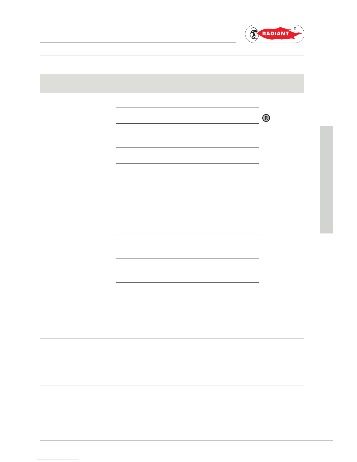
2.2.15. FAULT SIGNALLING CODES
CODE FAULT POSSIBLE CAUSE SOLUTION RESET
E01 FLAME BLOCK NO FLAME LIGHT UP MANUAL RESET
(PRESS THE RESET ‘
’ KEY).GAS MISSING; CHECK THE ADDUCTION NETWORK;
MASS OR BROKEN START-UP
ELECTRODE;
REPLACE IT;
GAS VALVE BROKEN; REPLACE IT;
SLOW LIGHT UP TOO LOW
ADJUSTMENT;
ADJUST MINIMUM OR SLOW LIGHT UP;
PRESSURE TOO HIGH AT THE
INPUT OF THE GAS VALVE
(ONLY FOR GPL BOILER).
CHECK THE MAXIMUM ADJUSTMENT
PRESSURE
WITH FLAME LIGHT UP
DETECTION ELECTRODE
BROKEN;
REPLACE IT;
DETECTION ELECTRODE
CABLE DISCONNECTED.
CHECK THE WIRING.
ELECTRICAL CURRENT
PHASE-PHASE
IF THE TENSION MEASURES BETWEEN
NEUTRAL AND GROUND IS ALMOST
EQUAL TO THE ONE MEASURED
BETWEEN PHASE AND GROUND, YOU
HAVE TO INSTALL A PHASE-PHASE
TRANSFORMER KIT (COD. 88021LA)
E02 SAFETY THERMOSTAT
(95°C)
THERMOSTAT
CABLE BROKEN OR
DISCONNECTED;
CHECK THE WIRING; AUTOMATIC.
BROKEN THERMOSTAT REPLACE IT.
Page 48
48
RBS 24 - RAD - ING - Manual - 1709.1_MIAB2013_R7
2 Codici di segnalazione anomalie_combinata_aperta_MIAB2013_EN
2. MAINTENANCE
SUPPORT CENTRE
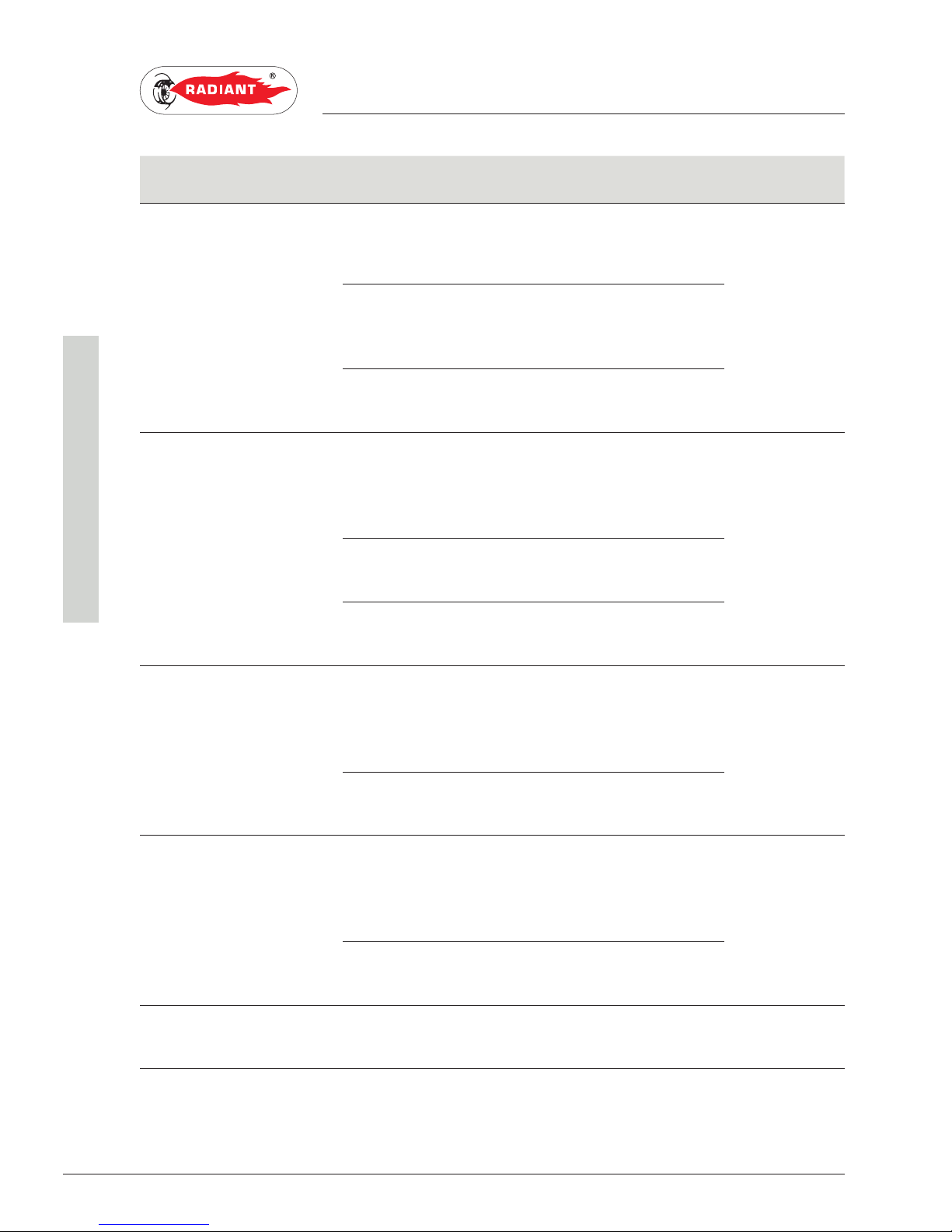
CODE FAULT POSSIBLE CAUSE SOLUTION RESET
E03 FLUE SAFETY
THERMOSTAT
THE CHIMNEY IS SHORT,
OF SMALL DIAMETER OR
CLOSED;
CHECK THE CHIMNEY DUCT; MANUAL RESET
SEE THE ‘CHIMNEY
SAFETY’ CHAPTER.
FLUE SAFETY THERMOSTAT
CABLE BROKEN OR
DISCONNECTED;
CHECK THE WIRING;
FLUE SAFETY THERMOSTAT
DEFECTIVE.
REPLACE IT.
E04 WATER MISSING IN THE
SYSTEM
INSUFFICIENT WATER
PRESSURE INSIDE THE
SYSTEM (LOWER THAN 0.3
BAR);
LOAD THE SYSTEM; AUTOMATIC.
WATER PRESSURE SWITCH
CABLE DISCONNECTED;
CHECK THE WIRING;
WATER PRESSURE SWITCH
BROKEN.
REPLACE IT.
E05 HEATING PROBE BROKEN OR INCORRECTLY
CALIBRATED PROBE
(RESISTANCE VALUE 10
KOHM AT 25 °C NTC);
REPLACE IT; AUTOMATIC.
DISCONNECTED OR WET
PROBE CONNECTOR.
CHECK THE WIRING.
E06 DOMESTIC CIRCUIT PROBE BROKEN OR INCORRECTLY
CALIBRATED PROBE
(RESISTANCE VALUE 10
KOHM AT 25 °C NTC);
REPLACE IT; AUTOMATIC.
DISCONNECTED OR WET
PROBE CONNECTOR.
CHECK THE WIRING.
E17 MODULATOR GAS VALVE MODULATOR
DEFECTIVE;
REPLACE IT; AUTOMATIC.
Page 49
49
RBS 24 - RAD - ING - Manual - 1709.1_MIAB2013_R7
2 Codici di segnalazione anomalie_combinata_aperta_MIAB2013_EN
2. MAINTENANCE
SUPPORT CENTRE
CODE FAULT POSSIBLE CAUSE SOLUTION RESET
E18 INSUFFICIENT
CIRCULATION
EXCHANGER OBSTRUCTED; CLEAN OR REPLACE THE EXCHANGER; AUTOMATIC.
CIRCULATOR BROKEN OR
DIRTY IMPELLER.
CLEAN THE IMPELLER OR REPLACE THE
CIRCULATOR.
E21 GENERAL INTERNAL
BOARD ERROR
INCORRECT SIGNAL
RECOGNITION BY THE
MODULATION BOARD
MICRO-PROCESSOR.
IF THE MODULATION BOARD DOES NOT
RESET THE ERROR AUTOMATICALLY,
REPLACE IT.
AUTOMATIC.
E22 PARAMETERS
PROGRAMMING REQUEST
MICRO=PROCESSOR
MEMORY LOSS.
PARAMETERS REPROGRAMMING. MANUAL RESET
(CUT OFF THE
TENSION).
E31 REMOTE CONTROLLER
INCOMPATIBLE
INDICATES THAT THE
REMOTE CONTROLLER
CONNECTED TO THE BOILER
IS NOT COMPATIBLE WITH
THE CIRCUIT BOARD
REPLACE IT WITH A COMPATIBLE
MODEL.
AUTOMATIC.
E40 SUPPLY VOLTAGE SUPPLY VOLTAGE OFF THE
OPERATION RANGE (d160
VOLTS).
CHECK THE POWER SUPPLY
NETWORK (THE ERROR DEACTIVATES
AUTOMATICALLY AS SOON AS THE
SUPPLY VOLTAGE FALLS BACK WITHIN
THE REQUESTED LIMITS).
AUTOMATIC.
E72 AIR PRESSURE SWITCH/
ELECTRIC FAN PRESSURE
SWITCH CHECK UP ERROR
CONNECTION ERROR OF
THE AIR PRESSURE SWITCH/
ELECTRIC FAN
AIR PRESSURE SWITCH
CONTACT BLOCKED;
ELECTRIC FAN DEFECTIVE;
CHECK THE WIRING;
REPLACE THE AIR PRESSURE SWITCH;
REPLACE IT;
MANUAL RESET
(PRESS THE RESET ‘
’ KEY).
Page 50
50
RBS 24 - RAD - ING - Manual - 1709.1_MIAB2013_R7
2 Sicurezza camino_MIAH6_RBC 24_NC_EN
2. MAINTENANCE
SUPPORT CENTRE
2.2.3. CHIMNEY SAFETY
The boiler is equipped with a flue safety thermostat
device, which controls the correct evacuation of the
combustion gases.
This device, by blocking the gas flow to the burner,
put the boiler in safety if the flue hood has a partial
or total obstruction, or the section is not suitable
for the combustion gases exhaust.
In case of the flue safety thermostat intervention
with consequent blocking of the boiler, it will be
necessary to act promptly and appropriately to
solve the defect of the flues exhaust.
DANGER
It is absolutely forbidden to tamper with
the flue safety thermostat or to put it out of use, as
this would compromise security.
In case of a block, before resetting the flue safety
thermostat, proceed with the following operations:
› check the exhaust section;
› check that there are no obstructions that prevent
the correct flues exhaust.
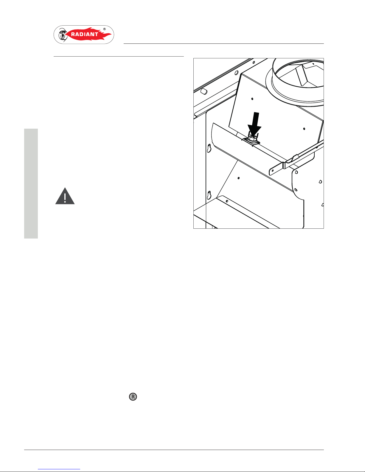
Flue safety thermostat resetting:
› press the button placed between the two
electrical contacts of the flue safety thermostat
(see fig.1);
› perform a test run on the flue safety thermostat,
checking with a tester the electrical continuity on
the contacts. In case the flue safety thermostat
is broken, replace it using only the original spare
part;
› press the “RESET” button ‘
’.
fig.1
Page 51
51
RBS 24 - RAD - ING - Manual - 1709.1_MIAB2013_R7
2 Codici di segnalazione funzioni attive_bitermica_solo risc_MIAB2013_EN
2. MAINTENANCE
SUPPORT CENTRE
2.2.16. ACTIVE FUNCTIONS SIGNALLING CODES
CODE FUNCTION DESCRIPTION
F07 CHIMNEY SWEEP ACTIVE YOU CAN ACTIVATE IT BY HOLDING BOTH THE ‘
’ AND ‘ ’ DOMESTIC CIRCUIT
KEYS FOR 3 SECONDS AND YOU CAN DEACTIVATE IT BY TURNING THE BOILER OFF. THIS
FUNCTION BRINGS THE BOILER TO ITS MAXIMUM HEATING PRESSURE FOR 15 MINUTES
DEACTIVATING THE MODULATION FUNCTION. GENERALLY USED FOR PERFORMING THE
COMBUSTION TESTS.
F08 HEATING CIRCUIT ANTI-FREEZE IT ACTIVATES AUTOMATICALLY WHEN THE HEATING PROBE DETECTS A TEMPERATURE
OF 5°C. THE BOILER OPERATES AT MINIMUM GAS PRESSURE WITH THE DIVERTER
VALVE SET TO ‘WINTER’ MODE. IT DEACTIVATES WHEN THE HEATING PROBE DETECTS A
TEMPERATURE OF 30°C.
Page 52
52
RBS 24 - RAD - ING - Manual - 1709.1_MIAB2013_R7
2 Trasformazione tipo gas_trad_MIAB2013_EN
2. MAINTENANCE
SUPPORT CENTRE
2.2.17. GAS TYPE TRANSFORMATION
WARNING
Make sure that the gas adduction tube is
suitable for the new type of fuel with which the boiler
is supplied.
WARNING
Once transformation is complete, adjust
the boiler again by following the instructions in the
relevant paragraph and apply the new identification
plate in the gas transformation kit.
WARNING
Remember that when using LPG gas,
mechanical couplings must not be sealed with flax.
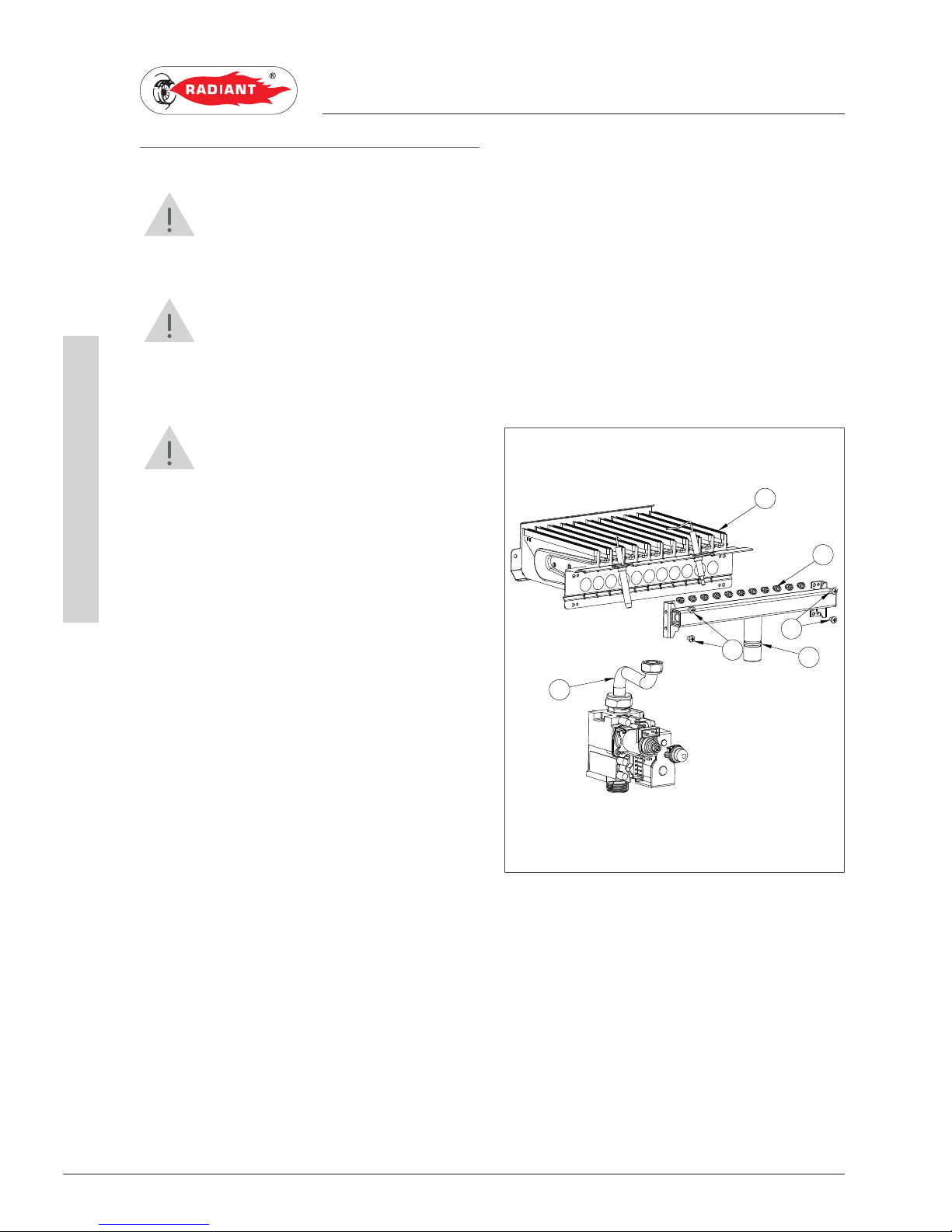
In order to carry out transformation, proceed as
follows (see fig. 1):
1. cut off the electrical supply to the boiler;
2. close the gas tap;
3. remove the boiler's front casing and rotate the
control panel (refer to the 'ACCESSING THE
BOILER' chapter).
4. unscrew the gas connector '1' using a 24mm
open wrench and separate the collector '2'
from the burner '3' by unscrewing the screws
'4';
5. replace the nozzles '5' on the collector using
a 7mm socket wrench. The nozzles must be
refitted with new seals;
6. re-fit the collector '2' to the burner and replace
the connector '1'. After every dismantling and
refitting of gas connectors, carefully check for
any leaks by using soapy water;
7. affix the two 'gas data' stickers in the
transformation kit, one on the inside of the
control panel covering the existing plate, and
the other inside the front panel of the boiler,
near the data plate. On the latter, data relating
to the old type of gas in use must be deleted
with a permanent marker.
8. Set the parameter value for the new type of gas
in use (see the instructions in the 'PARAMETER
TABLE MIAB2013' and 'ACCESSING AND
PROGRAMMING THE PARAMETERS'
chapters);
9. adjust the minimum and maximum pressures
(see the 'GAS PRESSURE CHECK AND
CALIBRATION' chapter).
4
5
3
2
1
4
fig. 1
Page 53

The operations described in this section are addressed to
all those who will use the machine. The machine must be
used and accessed only by qualified operators that fully
read and understood the User section, paying particular
attention to the warnings.
1. USER SECTION3. USER SECTION
Page 54
54
RBS 24 - RAD - ING - Manual - 1709.1_MIAB2013_R7
3 Avvertenze generali per l'utilizzo_EN
3. USE
USER
3.1. USE
3.1.1. GENERAL USE WARNINGS
WARNING
Before starting the boiler the User must
make sure that the First start-up certificate has the
stamp of the technical Support Centre proving the
testing and the first start-up of the boiler.
WARNING
To validate the warranty, the boiler must
be started by a technical Support Centre authorized
by RADIANT no later than 30 days from the date of
installation.
WARNING
In order to take advantage of the guarantee
provided by the manufacturer, the customer should
carefully and exclusively observe the instructions
given in the USER section of the manual.
ATTENTION
This machine may be used only for the
purpose for which it has been designed: heat water
to a temperature below boiling point at atmospheric
pressure. Any other use is considered wrong and
dangerous. The manufacturer is excluded from
any contractual or out of contract responsibility for
damage caused to people, animals or property due to
incorrect use.
DANGER
The boiler should not be used by persons
(including children) with reduced physical, sensory or
mental capacities or without suitable knowledge or
experience unless they are instructed on the device
use or monitored by a person responsible for their
safety.
DANGER
DO NOT obstruct the air vents of the
location in which the gas device is installed to prevent
the formation of toxic explosive mixes.
DANGER
If you sense a gas odour in the location in
which the boiler is installed, proceed as follows:
› DO NOT use electrical switches, the telephone or
any other device that might generate electrical
discharges or sparks;
› Immediately open all doors and windows to
create an air exchange that can quickly clean the
location;
› Close the gas valves;
› Request immediate intervention of qualified
staff.
DANGER
The use of the electrical power boiler
implies respecting some fundamental rules such as:
› DO NOT touch the device with wet and/or humid
parts and/or with bare feet;
› DO NOT pull the electrical cables;
› DO NOT leave the device exposed to atmospheric
agents (rain, sun, etc.) unless specifically
intended;
› in case of cable damage, turn off the device and
contact qualified professional staff to replace it.
Page 55
55
RBS 24 - RAD - ING - Manual - 1709.1_MIAB2013_R7
3 Pannello comandi_combinata_MIAB_R7_EN
3. USE
USER
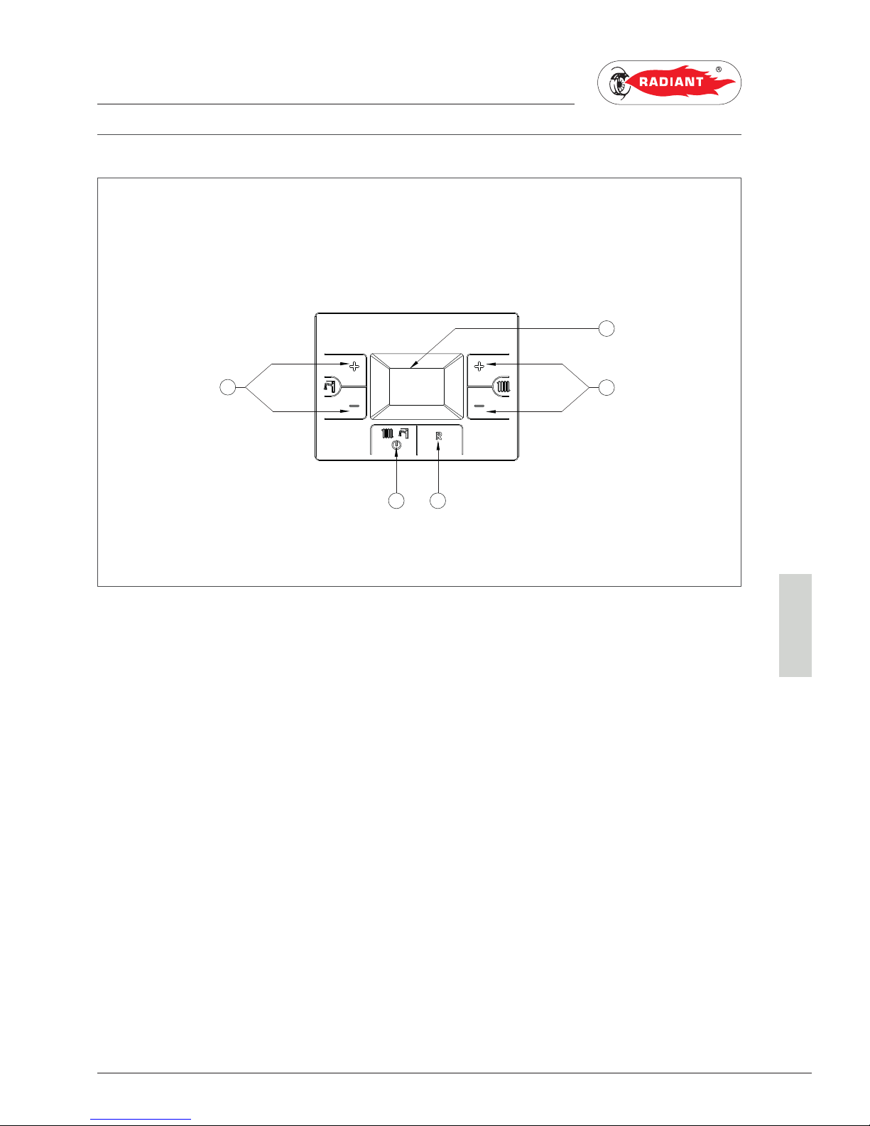
3.1.2. CONTROL PANEL
KEY
1. DOMESTIC HOT WATER TEMPERATURE
ADJUSTMENT KEYS
2. OPERATING MODE SELECTION KEY: SUMMER
/ HEATING ONLY / WINTER / OFF
3. RESET KEY: ANOMALY RESET
4. HEATING TEMPERATURE ADJUSTMENT KEYS
5. DISPLAY
4
1
2 3
5
Page 56
56
RBS 24 - RAD - ING - Manual - 1709.1_MIAB2013_R7
3 Icone del display_combinata_MIAB_EN
3. USE
USER
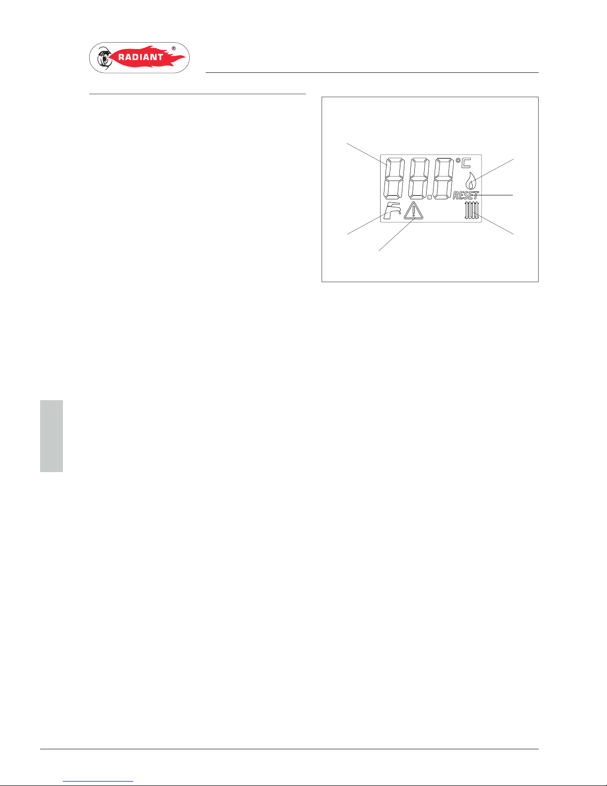
3.1.2. DISPLAY ICONS
KEY
1. INDICATION OF PARAMETER NUMBER OR
DISPLAYED INFO CODE.
2. FLAME PRESENT SIGNALLING.
3. ERROR DISPLAY THAT CAN BE RESET.
4. OPERATION IN HEATING MODE ENABLED.
5. PARAMETERS PROGRAMMING FUNCTION
ACTIVE.
6. OPERATION IN DOMESTIC MODE ENABLED.
4
5
6
1
2
3
fig. 1
Page 57
57
RBS 24 - RAD - ING - Manual - 1709.1_MIAB2013_R7
3 Visualizzazioni del menù Info_MIAB2013_firm.H070C_EN
3. USE
USER
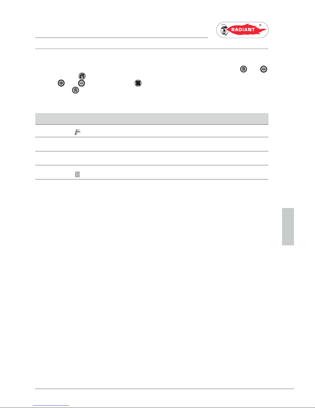
3.1.3. INFO MENU DISPLAY DATA
To view the boiler data from the info menu you just have to press at the same time the keys ‘ ’ and ‘ ’
of the DHW circuit
for 2 seconds. It will be displayed the info code alternated to the associated value.
Use keys ‘
’ and ‘ ’ of the heating circuit to scroll through the list of displayed data. To exit display
mode press the
‘ ’ key.
LIST OF DISPLAYED DATA
INFO CODE ICON DESCRIPTION
0 DOMESTIC CIRCUIT PROBE TEMPERATURE
1 EXTERNAL PROBE TEMPERATURE
2 BURNER ACTUAL OUTPUT POWER (EXPRESSED IN PERCENTAGE)
3 HEATING CIRCUIT TEMPERATURE
Page 58
58
RBS 24 - RAD - ING - Manual - 1709.1_MIAB2013_R7
3 Accensione_Modalità di funzionamento_Antigelo_MIAB_EN
3. USE
USER
3.1.4. START-UP
Before starting the boiler make sure that it is
powered and that the gas tap below the boiler is
open.
To start the boiler press the function key ‘
’ and
select the desired operating mode. If the symbol
is displayed fixed, it means that the function was
activated.
3.1.5. OPERATING MODE
SUMMER MODE
In this mode the boiler meets only the demands of
domestic hot water.
To switch the boiler to SUMMER operating mode,
press the function key ‘
’, the symbol ‘ ’
will appear fixed on the display, indicating that the
function is enabled.
Whenever hot domestic water is needed the
automatic start-up system will start the burner;
this is indicated by displaying the symbol ‘
’
blinking.
ONLY HEATING MODE
In this mode the boiler meets only the demands of
heating.
To switch the boiler to ONLY HEATING operating
mode, press the function key ‘
’, the symbol ‘
’ will appear fixed on the display, indicating that
the function is enabled.
Whenever heating energy is needed to heat the
rooms the automatic start-up system will start the
burner; this is indicated by displaying the symbol ‘
’ blinking.
WINTER MODE
In this mode the boiler meets the demands of
heating and of domestic hot water.
To switch the boiler to WINTER operating mode,
press the function key ‘
’, the symbols ‘
and
’ will appear fixed on the display, indicating
that the function is enabled.
Whenever heating energy and domestic hot water
are needed the automatic start-up system will
start the burner; this is indicated by displaying the
symbol ‘
and ’ blinking.
ADJUSTING THE HEATING TEMPERATURE
You can adjust the temperature using keys ‘
’ and
‘
’ of the heating circuit :
· press key ‘
’ to decrease the temperature.
· press key ‘
’ to increase the temperature.
The heating temperature adjustment field ranges
from 30 °C to 80 °C (25 °C – 45 °C for floor systems).
DOMESTIC HOT WATER TEMPERATURE
ADJUSTMENT
You can adjust the temperature using keys ‘
’ and
‘
’ of the domestic circuit :
· press key ‘
’ to decrease the temperature.
· press key ‘
’ to increase the temperature.
The hot domestic water temperature adjustment
field ranges from 35 °C to 60 °C.
OFF MODE
In this mode the boiler no longer meets the heating
and domestic hot water demands, the anti-freeze,
Page 59

59
RBS 24 - RAD - ING - Manual - 1709.1_MIAB2013_R7
3 Accensione_Modalità di funzionamento_Antigelo_MIAB_EN
3. USE
USER
pump anti-locking and diverter valve anti-locking
systems still remain active.
To switch the boiler to OFF operating mode, press
the function key ‘
’, the message ‘OFF’
indicating that the function is enabled.
If the boiler was previously running, it will be turned
off and the post-ventilation and post-circulation
functions will be enabled.
If you have to deactivate the boiler for a long period
of time, proceed as follows:
› contact the Technical support centre that will
empty the water system, where no anti-freeze is
intended, and will cut off the power, water and
gas supply.
› Or leave the boiler in OFF operating mode
keeping active the electrical and gas supplies so
that the anti-freeze function may activate.
3.1.6. INFORMATIONAL NOTE ON
ANTI-FREEZE FUNCTION
The boiler is protected against freezing thanks to
the electronic board preparation with functions
that start the burner and heat the concerned parts
when their temperature goes below the minimum
pre-set values.
WARNING
This function is available only if:
› the boiler is powered;
› the gas supply is open;
› the pressure of the system is proper;
› the boiler is not blocked.
Page 60
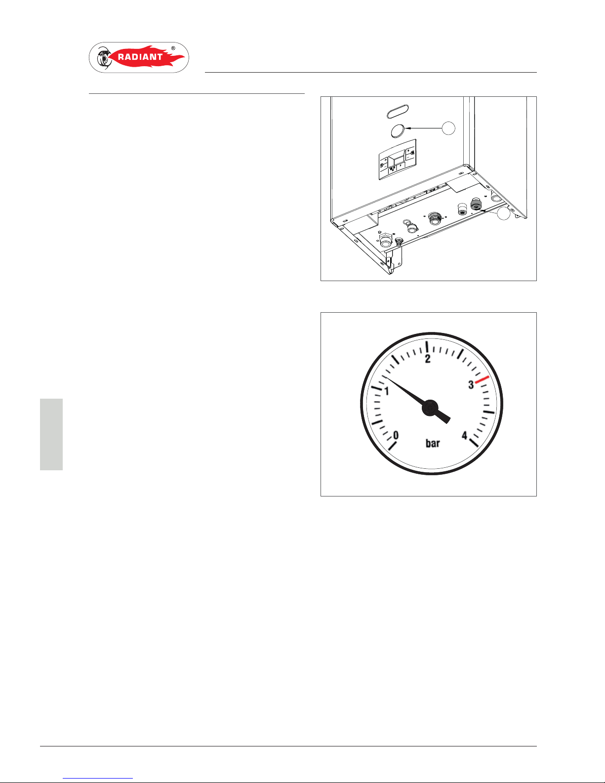
60
RBS 24 - RAD - ING - Manual - 1709.1_MIAB2013_R7
3 Riempimento dell'impianto_RBS 24_R7_EN
3. USE
USER
3.1.7. SYSTEM FILLING
To restore the water pressure inside the system
open the loading tap “R” (fig. 1) and make sure
using pressure gauge “M” (fig. 1), that the system
pressure reaches 1.2 bar (see fig. 2).
After performing this operation, make sure that the
loading tap “R” (fig. 1) is properly closed.
M
R
fig. 1
fig. 2
Page 61
61
RBS 24 - RAD - ING - Manual - 1709.1_MIAB2013_R7
3 Codici di segnalazione anomalie_combi_aperta_MIAB2013_EN
3. USE
USER
3.1.8. FAULT SIGNALLING CODES
The boiler might signal some faults by displaying a code. Below you have a list of the codes and of the
operations to be performed in order to unlock the boiler.
CODE FAULT INTERVENTION
E01 FLAME BLOCK MAKE SURE THAT THE BOILER AND CONTACTOR GAS VALVES ARE OPEN.
PRESS THE RESET ‘
’ BUTTON ON THE CONTROL PANEL TO RESET THE FAULT,
AS SOON AS THE ERROR CODE DISAPPEARS FROM THE DISPLAY, THE BOILER
WILL START AUTOMATICALLY.
IF THE BLOCK PERSISTS CONTACT THE TECHNICAL SUPPORT CENTRE.
E02 SAFETY THERMOSTAT (95 °C) CONTACT THE TECHNICAL SUPPORT CENTRE.
E03 FLUE SAFETY THERMOSTAT CONTACT THE TECHNICAL SUPPORT CENTRE.
E04 WATER MISSING IN THE SYSTEM IF THE SYSTEM PRESSURE IS BELOW 1.2 BAR, FILL THE SYSTEM AS DESCRIBED IN
CHAPTER “SYSTEM FILLING”.
IF THE BLOCK PERSISTS CONTACT THE TECHNICAL SUPPORT CENTRE.
E05 HEATING PROBE CONTACT THE TECHNICAL SUPPORT CENTRE.
E06 DOMESTIC CIRCUIT PROBE CONTACT THE TECHNICAL SUPPORT CENTRE.
E17 MODULATOR CONTACT THE TECHNICAL SUPPORT CENTRE.
E18 INSUFFICIENT CIRCULATION CONTACT THE TECHNICAL SUPPORT CENTRE.
E21 GENERAL INTERNAL BOARD ERROR CUT OFF THE POWER SUPPLY FROM THE MAIN SWITCH AND THEN RESTORE
IT, AS SOON AS THE ERROR CODE DISAPPEARS, THE BOILER WILL RESTART
AUTOMATICALLY.
IF THE BLOCK PERSISTS CONTACT THE TECHNICAL SUPPORT CENTRE.
E22 PARAMETERS PROGRAMMING REQUEST CUT OFF THE POWER SUPPLY FROM THE MAIN SWITCH AND THEN RESTORE
IT, AS SOON AS THE ERROR CODE DISAPPEARS, THE BOILER WILL RESTART
AUTOMATICALLY.
IF THE BLOCK PERSISTS CONTACT THE TECHNICAL SUPPORT CENTRE.
E31 REMOTE CONTROLLER INCOMPATIBLE CONTACT THE TECHNICAL SUPPORT CENTRE.
E40 SUPPLY VOLTAGE CONTACT THE TECHNICAL SUPPORT CENTRE.
Page 62

62
RBS 24 - RAD - ING - Manual - 1709.1_MIAB2013_R7
3 Codici di segnalazione anomalie_combi_aperta_MIAB2013_EN
3. USE
USER
CODE FAULT INTERVENTION
E72 FUMES THERMOSTAT CHECK UP ERROR CONTACT THE TECHNICAL SUPPORT CENTRE.
Page 63

63
RBS 24 - RAD - ING - Manual - 1709.1_MIAB2013_R7
3 Codici di segnalazione funzioni attive_bitermica_solo risc_MIAH6_MIAB_EN
3. USE
USER
3.1.9. ACTIVE FUNCTIONS
SIGNALLING CODES
CODE FUNCTION INTERVENTION
F08 HEATING ANTI-
FREEZE FUNCTION
ACTIVE
WAIT UNTIL THE OPERATION
IS COMPLETED
Page 64
64
RBS 24 - RAD - ING - Manual - 1709.1_MIAB2013_R7
3 Manutenzione_Pulizia_Smaltimento_EN
3. USE
USER
3.1.7. MAINTENANCE
To ensure proper boiler safety and efficiency, please
contact RADIANT technical support network to
check the device every year.
An accurate maintenance should improve system
management.
3.1.8. COVER CLEANING
Clean the cover of the device using a wet cloth and
come neutral soap.
WARNING
DO NOT use abrasive or powder detergents
as they might damage the plastic cover and control
elements.
3.1.9. DISPOSAL
The boiler and all its accessories must be
differentiated, suitably disposed of in accordance
with the standards in force.
The use of the symbol WEEE
(Waste Electrical and Electronic
Equipment) shows that this
product can not be dismantled as domestic waste.
Proper dismantle of this product helps preventing
potentially negative consequences on human
health and environment.
Page 65

Page 66

Page 67

Page 68

RADIANT BRUCIATORI s.p.a.
Via Pantanelli, 164/166 - 61025 Loc. Montelabbate (PU)
Tel. +39 0721 9079.1 • fax. +39 0721 9079279
e-mail: info@radiant • Internet: http://www.radiant.it
 Loading...