

Radiant R2KA 24 /8 Installation, Use And Maintenance Manual
R2KA 24 /8 - RAD - ING - Manuale - 1507.1
Installation, Use
and Maintenance Manual
for model
0694
R2KA 24 /8
Condensing boiler with integrated heat
exchanger for domestic hot water side
and storage
2
R2KA 24 /8 - RAD - ING - Manuale - 1507.1
R2KA 24.8_EN
SUMMARY
SUMMARY
INTRODUCTION 4
1. INSTALLER SECTION 7
1.1. INSTALLATION 8
1.1.1. GENERAL INSTALL ATION WARNINGS 8
1.1.2. BOILER LOCATION ENVIRONMENTAL REQUIREMENTS 8
1.1.3. REFERENCE LEGISL ATION 9
1.1.4. UNPACKING 10
1.1.5. OVER ALL DIMENSIONS 11
1.1.6. JIG 11
1.1.7. POSITIONING AND MINIMAL TECHNICAL SPACES 12
1.1.8. CIRCULATOR PREVALENCE/FLOW DIAGRAM 13
1.1.9. HYDR AULIC CONNECTION 14
1.1.10. D.H.W. CIRCULATING LOOP 15
1.1.11. SYSTEM FILLING 16
1.1.12. FILLING THE CONDENSATE COLLECTION SIPHON 17
1.1.13. ANTI-FREEZE PROTECTION 18
1.1.14. GAS CONNECTION 19
1.1.15. EL ECTRICAL CONNECTION 19
1.1.16. POWER SUPPLY 20
1.1.17. OPTIONAL ELECTRICAL CONNECTIONS 21
1.1.18. FUME EXHAUST FITTINGS 23
1.1.19. INSTALL ATION MODES (IN ACCORDANCE WITH UNI 10642) 24
1.1.20. TYPES OF FUME EXHAUST SYSTEMS 26
2. SUPPORT CENTRE SECTION 29
2.1. FIRST START-UP 30
2.1.1. PRELIMINARY OPERATIONS FOR FIRST START-UP 30
2.1.2. BOILER COMMISSIONING 31
2.1.3. CO2 VALUE CHECK AND CALIBRATION 32
2.1.4. ACCESSING AND PROGRAMMING THE PARAMETERS 33
2.1.5. DIGITECH CS PARAMETERS TABLE 35
2.1.6. ELECTRIC FAN FREQUENCY/HEAT CAPACITY DIAGRAM 42
2.2. MAINTENANCE 43
2.2.7. GENERAL MAINTENANCE WARNINGS 43
2.2.8. TECHNICAL DATA 45
2.2.9. TECHNICAL ASSEMBLY 47
2.2.10. HYDRAULIC BOARD 48
2.2.11. 3-WAY VALVE OPERATION 49
3
R2KA 24 /8 - RAD - ING - Manuale - 1507.1
R2KA 24.8_EN
SUMMARY
2.2.12. WIRING DIAGRAM 50
2.2.13. ACCESSING THE BOILER 51
2.2.14. ACCESSING THE ELECTRONIC BOARD 52
2.2.15. SYSTEM EMPTYING 53
2.2.16. BOILER MAINTENANCE 54
2.2.17. FAULT SIGNALLING CODES 55
2.2.18. ACTIVE FUNCTIONS SIGNALLING CODES 58
2.2.19. GAS T YPE TRANSFORMATION 59
3. USER SECTION 61
3.1. USE 62
3.1.1. GENERAL USE WARNINGS 62
3.1.2. CONTROL PANEL 63
3.1.3. DISPLAY ICONS 64
3.1.4. INFO MENU DISPLAY DATA 65
3.1.5. START-UP 66
3.1.6. OPERATING MODE 66
3.1.7. INFORMATIONAL NOTE ON ANTI-FREZZE FUNCTION 67
3.1.8. SYSTEM FILLING 68
3.1.9. FAULT SIGNALLING CODES 69
3.1.10. ACTIVE FUNCTIONS SIGNALLING CODES 71
3.1.11. MAINTENANCE 72
3.1.12. COVER CLEANING 72
3.1.13. DISPOSAL 72
4
R2KA 24 /8 - RAD - ING - Manuale - 1507.1
_Prefazione_EN
2.
INTRODUCTION
WARNING
Before starting any operation it is mandatory to
read this instruction manual, in relation to the
activities to be carried out as described in each
relevant section. Proper operation and optimal
performance of the boiler are ensured by strict
compliance with all the instructions given in this
manual.
The installation, use and maintenance manual is
an integral and essential part of the product and
must be delivered to the user.
MANUAL USERS
The manual users are all those who install, use
and maintain the boiler.
The boiler must be used and accessed only by
qualified operators that fully read and understood
the use and maintenance manual, paying par ticular
attention to the warnings.
READING AND SYMBOLS OF THE MANUAL
To ease the understanding of this manual,
recurrent symbols where used, in particular:
› On the outer margin of the page is placed a
thumb index indicating the type of user to which
the instructions in that section address.
› The titles are differentiated by thickness and
size in accordance with their hierarchy.
› The images contain important parts described
in the text, marked with numbers or letters.
› (See chap “chapter name”): this entry indicates
another section in the Manual that you should
refer to.
› Device: this term is used referring to the boiler.
DANGER
It identifies an information related to a
general danger that if not complied with, may cause
serious personal damage or even death.
ATTENTION
It identifies an information that if not
complied with may cause small or medium level
lesions to the person or serious deterioration to the
boiler.
WARNING
It identifies a precaution information that
must be observed in order to avoid damaging the
machine or parts of it.
MANUAL STORAGE
The manual must be carefully stored and replaced
in case of deterioration and/or low legibility.
If you misplace the use and maintenance manual,
you can request it from the Technical Support
Centre giving the serial number and model of the
boiler indicated on the plate placed on the right
side of its casing.
As an alternative, the use and maintenance manual
can be downloaded free from the on-line site www.
radiant.it, accessing the “download” section and
entering the boiler model.
INTRODUCTION

5
R2KA 24 /8 - RAD - ING - Manuale - 1507.1
_Prefazione_EN
2.
MANUFACTURER WARRANTY AND
RESPONSIBILITY
The warranty of the Manufacturer is provided only
through its own authorized Technical Support
Centres, listed for each Region and Provence on
the site www.radiant.it, and covers all conformity
defects at the moment of sale.
The technical and functional features of the device
are ensured by its use in compliance:
1. with the use and maintenance instructions
contained in the manuals accompanying the
product, the content of which the customer
certifies that he is aware;
2. with the conditions and purposes to which
assets of the same type are intended.
For more information on the warranty validity,
its duration, the obligations and the exemptions,
please consult the First start-up certificate
attached to this manual.
The manufacturer reserves:
› the right to modify the tools and relative
technical documentation without any obligation
to third parties;
› the material and intellectual ownership of
this manual and forbids its distribution and
duplication, even partial, without prior written
authorization.
PRODUCT CONFORMITY
RADIANT BRUCIATORI spa with reference to art.
5 of DPR n 447 dated 06/12/1991, “Regulation
implementing of law 5 March 1990, n 46” and
in compliance with law 6 December 1971, n
1083 “Safety standards for the use of fuel gas”,
declares that its gas boilers are professionally
manufactured.
All boilers obtained their CE certification (D.M. 2
April 1998 regulation implementing art.32 Law
10/91) and comply, from technical and functional
point of view with the requirements provided in
standards:
›UNI-CIG 7129/08
› UNI EN 297 for B-TYPE GAS DEVICES WITH
HEAT CAPACITY d 70 kW
› EN 483 for C-TYPE GAS DEVICES WITH HEAT
CAPACITY d 70 kW
› UNI EN 677 for CONDENSING GAS DEVICES
WITH HEAT CAPACITY d 70 kW
› Performance at 100% Pn and 30% (partial load
Pn) - D.P.R. 412/93 (regulation implementing
Law 10/91 art. 4, paragraph 4) and subsequent
modifications
The gas boilers also comply with the directives
below:
› GAS DIRECTIVE 2009/142/CE
› PERFORMANCE DIRECTIVE 92/42 CEE
› ELECTROMAGNETIC COMPATIBILITY
DIRECTIVE 2004/108/CE
› LOW VOLTAGE DIRECTIVE 2006/95/CEE
The materials used such as copper, brass,
stainless steel create a homogeneous, compact
and functional assembly, easy to install and
manage. In its simplicity, the boiler is equipped
with all accessories necessary to render it a
veritable independent heating unit. All boilers
are tested and delivered with a quality certificate
signed by the tester.
INTRODUCTION

The installation operations described in this section should
be performed only by qualified personnel, having the
appropriate technical training in the field for the installation
and maintenance of components of civil and industrial
domestic hot water production and heating plants as
provided by art. 3 of D.M. n°37 dated 22.01.2008.
1. INSTALLER SECTION
8
R2KA 24 /8 - RAD - ING - Manuale - 1507.1
1 Avve rte nze generali per l'ins ta lla zio ne_ Lo ca le caldaia _EN
1. INSTALLATION
INSTALLER
1.1. INSTALLATION
1.1.1. GENERAL INSTALL ATION
WARNINGS
WARNING
This machine may be used only for the
purpose for which it has been designed: heat water
to a temperature below boiling point at atmospheric
pressure. Any other use is considered wrong and
dangerous. The manufacturer is excluded from
any contractual or out of contract responsibility for
damage caused to people, animals or property due
to errors during installation.
WARNING
This boiler should be installed only
by qualified personnel, having the appropriate
technical training in the field for the installation and
maintenance of components of civil and industrial
domestic hot water production and heating plants as
provided by art. 3 of D.M. n°37 dated 22.01.2008.
WARNING
After having removed the packing, make
sure the equipment is intact. In case of doubt, do not
use the equipment and contact the supplier.
BEFORE INSTALLING THE BOILER, THE
INSTALLER MUST MAKE SURE THAT THE
FOLLOWING CONDITIONS ARE MET:
› The device is connected to a heating plant and a
water supply network appropriate for its power
and performance.
› The location must be properly vented through
an air vent.
The air vent must be placed at floor level to prevent
it from being obstructed, protected by a grid that
does not hamper the useful section of passage.
› The device is suitable for use with the type of
gas available by checking the boiler data plate
(placed on the inner side of the front casing.
› Make sure that the tubes and couplings are
perfectly sealed, without any gas leaks.
› Make sure that the grounding system works
properly.
› Make sure that the electrical systems is
suitable for the maximum power absorbed by
the equipment, value indicated on the data plate.
WARNING
Use only original RADIANT optional or kit
accessories (including electrical).
1.1.2. BOILER LOCATION
ENVIRONMENTAL
REQUIREMENTS
Two devices intended for the same use in the
same location or in directly communicating
locations, generating a total heat capacity of
over 35 kW, represent a heating unit, subjected
to the requirements provided by D.M. n°74 dated
12.04.1996 “Approval of the fire prevention technical
rule for design, manufacture and operation of gassupplied thermal plants”.
As the device's heat capacity is lower than 35 kW,
the location housing the boiler must meet the
provisions laid down by technical standard UNI
7129-3: 2008.
The capacities of more devices intended for
different uses (e.g. heating and cook top), installed
in a single housing unit must not be added.
9
R2KA 24 /8 - RAD - ING - Manuale - 1507.1
1 Avve rte nze generali per l'ins ta lla zio ne_ Lo ca le caldaia _EN
1. INSTALLATION
INSTALLER
The device's installation location should be vented
due to the presence of threaded joints on the gas
adduction line (UNI 7129-3: 2008). The location
should be therefore provided with vents as to
ensure air exchange, with output grid in the natural
accumulation area of eventual gas losses.
WARNING
If the temperature in the boiler installation
location goes below -10° centigrades, please fill
the plant with anti-freeze liquid and insert and
electrical resistances kit (see chapter ‘ANTI-FREEZE
PROTECTION’).
1.1.3. REFERENCE LEGISLATION
THE INSTALLER MUST FOLLOW THE DIRECTIVES
BELOW:
› Standards UNI 7129-3: 2008 / 7131 and updates;
› Law dated 9 January 1991 n° 10 and relative
Regulation Implementing (DPR 412/93, modified
by DPR 551/99);
› Dispositions issued by Fire Fighters, local gas
Company and Municipal Regulations.
› Instructions provided by the supplier.
10
R2KA 24 /8 - RAD - ING - Manuale - 1507.1
1 Disimballo_murale_EN
1. INSTALLATION
INSTALLER
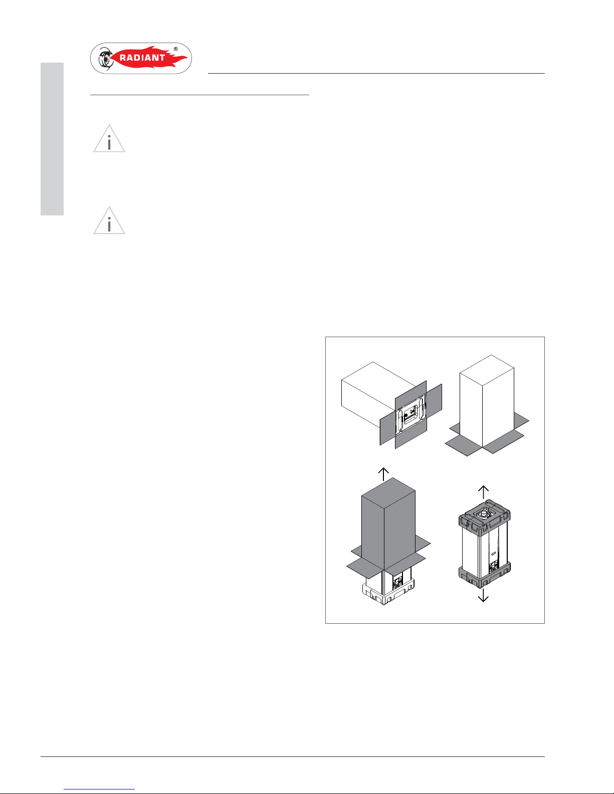
1.1.4. UNPACKING
WARNING
Please unpack the boiler just before
installing it. The Company is not responsible for
the damages caused to the device due to incorrect
storage.
WARNING
The packing elements (cardboard box,
wooden crate, nails, fasteners, plastic bags, expanded
polystyrene, etc.) must be kept out of the reach of
children as they may be dangerous. Therefore they
should be dismantled suitably differentiating them in
accordance with the standards in force.
To unpack the boiler, proceed as follows:
› Place the packed boiler on the floor (fig. 1-A)
and remove the fasteners opening the four flaps
of the box outwards.
› Turn the boiler at 90° holding it with your hand
(fig. 1-B).
› Lift the box (fig. 1-C) and remove the guards (fig.
1-D).
C
B
D
A
fig. 1
11
R2KA 24 /8 - RAD - ING - Manuale - 1507.1
1 Dimensioni_R2KA .8_EN
1. INSTALLATION
INSTALLER
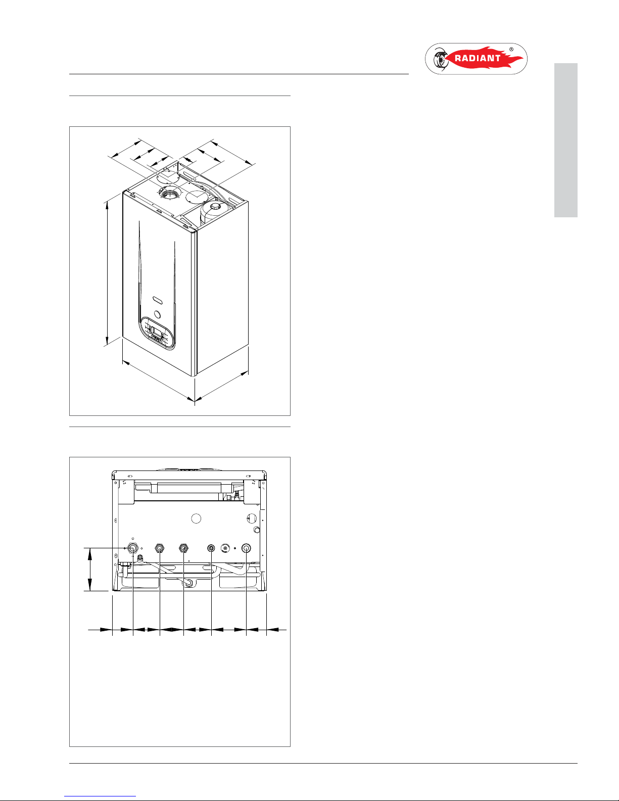
1.1.5. OVERALL DIMENSIONS
1.1.6. JIG
120
138
195
64
150
265
785
450
350
RC F AG
60 78 70 80 102 60
125
R- RETURN Ø 3/4
C - HOT Ø 1/2
G- GAS Ø 3/4
F- COLD Ø 1/2
A - INFEED Ø 3/4
12
R2KA 24 /8 - RAD - ING - Manuale - 1507.1
1 Spazi tecnici minimi e posizionamento_murale_v.2_EN
1. INSTALLATION
INSTALLER
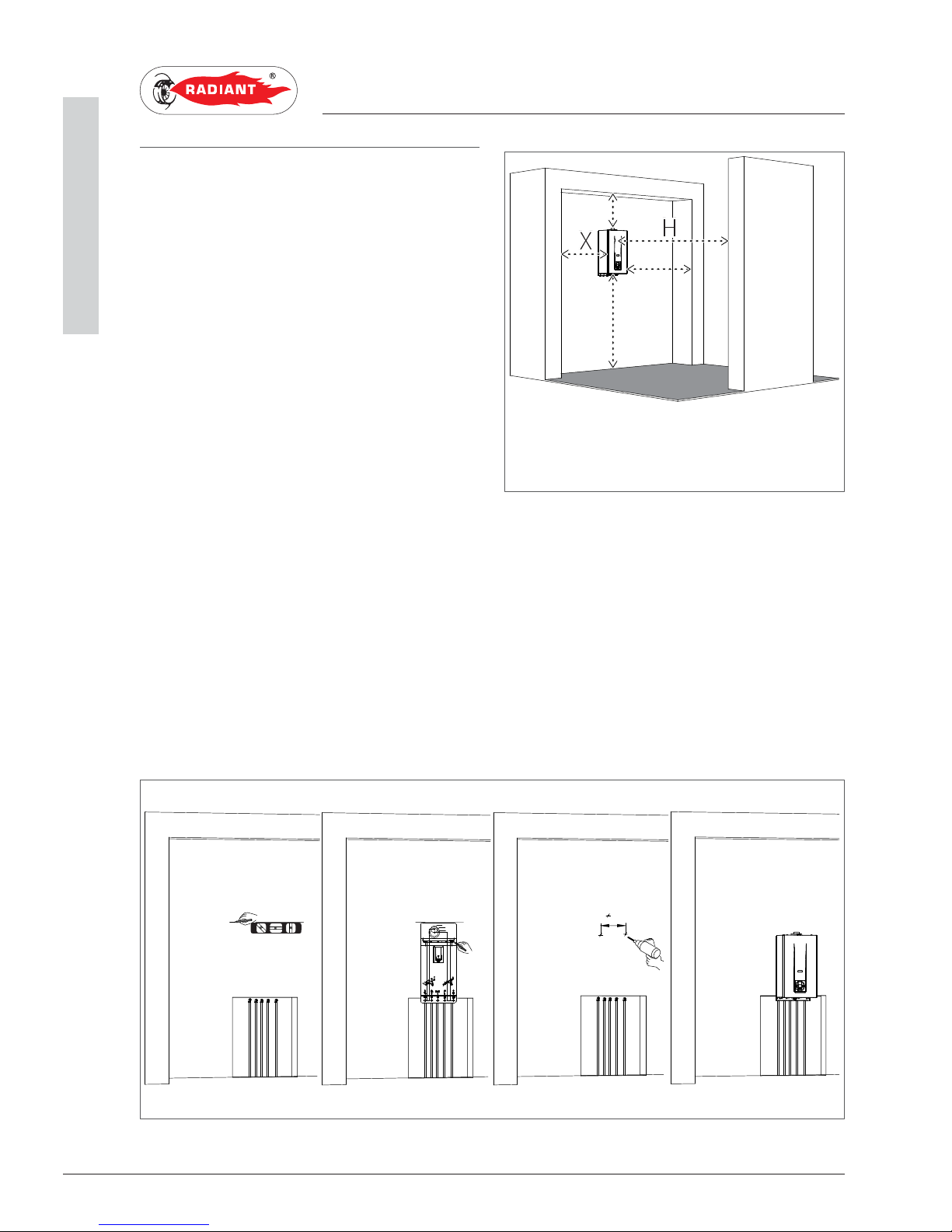
1.1.7. POSITIONING AND MINIMAL
TECHNICAL SPACES
The boiler must be installed only on a vertical solid
wall, able to sustain its weight.
In order to allow the access inside the boiler for
maintenance operations, you have to respect the
minimum technical spaces indicated in figure 1.
To facilitate the installation, the boiler is provided
with a jig that allows setting in advance the
connections to the tubes offering you the possibility
of connecting the boiler to completed masonry
works.
For machine positioning, proceed as follows (see fig. 2):
1. Trace a line using a spirit level (min. length 25 cm) on the installation wall.
2. place the top of the jig along the traced line respecting the distances of the water connections; then
mark the two points to insert the two knobs or the fasteners, then trace the points for the fume
exhaust fittings;
3. remove the jig and drill the wall;
4. hang the device using the knobs or the bracket and perform the connections.
3
1
42
70 80 10249 3178
Ø80
Ø125
Ø100
35826 26
54 54
821
681
699
302
785
H
B
A
Y
X
A - 200 mm
B - 300 mm
X - 60 mm
Y - 60 mm
H - 1000 mm
fig.1
fig.2
13
R2KA 24 /8 - RAD - ING - Manuale - 1507.1
1 Diagramma portata-prevalenza circolatore_R2K 24_v.3_EN
1. INSTALLATION
INSTALLER
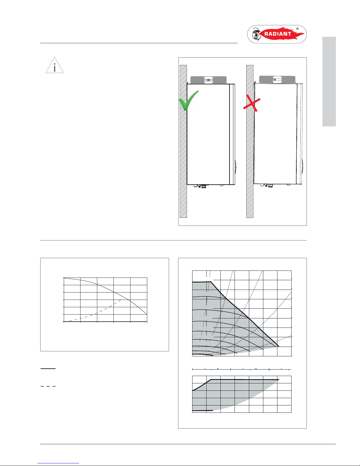
WARNING
Make sure, using a level, that the boiler
is properly inclined being levelled (see fig.1) so as to
allow the condense to drain.
1.1.8. CIRCULATOR PREVALENCE/FLOW DIAGRAM
III
Circulator priority maximum speed
Appliance Loss
fig.1
6
0
1
2
3
4
5
0 0.5 1 1.5 2 2.5
MSL 12/6 COMPACT
III
Wilo-Yonos PARA MSL 12/7.0
0 0,4 0,8 1,2 1,6 2,0 2,4
0 0,1 0,2 0,3 0,4 0,5 0,6 0,7
02468
0
1
2
3
4
5
6
7
8
0
10
20
30
40
50
70
60
80
0 0,4 0,8 1,2 1,6 2,0 2,4
0
10
20
30
40
4180/ 15
PWM1
4640/ 5
PWM1
3210/ 35
PWM1
2730/ 45
PWM1
2250/ 55
PWM1
1280/ 75
PWM1
1760/ 65
PWM1
800/ 85
PWM1
p/kPa
H/m
P
1
/W
Q/m³/ h
Q/l/s
Q/Igpm
Q/m³/ h
max.
max.
3700/ 25
PWM1
PREVALENCE (m)
FLOW RATE (m3/h)
6
0
1
2
3
4
5
0 0.5 1 1.5 2 2.5
14
R2KA 24 /8 - RAD - ING - Manuale - 1507.1
1 Allacciamento idraulico_combinata_EN
1. INSTALLATION
INSTALLER
1.1.9. HYDRAULIC CONNECTION
DANGER
Make sure that the tubes of the water and
heating plant are not used as grounding system for
the electrical plant. There are not suitable for such
use.
WARNING
To prevent voiding the warranty and to
ensure the proper operation of the boiler, please
wash the plant (if possible when hot) with suitable
pickling or descaling solutions in order to remove the
impurities coming from tubes and radiators.
WARNING
If the boiler is installed in a hydrostatic
position lower than those of the user devices
(radiators, fan coils, etc.), mount the shut-off valves
on the domestic water heating circuit to ease the
performance of the maintenance operations if it is
necessary only to empty the boiler.
WARNING
When connecting the equipment to
water supply, avoid excessive bending and recovery
operations from any off axis positioning that may
damage the tubes causing leaks, malfunction or
early wear.
WARNING
In order to avoid any vibrations and noises,
do not use tubes with small diameters or elbows with
small radius and significant cut-off of the passage
sections.
DOMESTIC CIRCUIT
In order to prevent limestone build-up and
damages to the domestic water heat exchanger,
the hardness of the domestic supply water
should not exceed 15 °f. However, please check
the characteristics of the water used and install
suitable treating devices.
The pressure of the cold infeed water should be
between 0.5 and 6 bar.
In case of greater pressure values, please install a
pressure reducer upstream from the boiler.
The heat exchanger coil cleaning frequency
depends on the hardness of the supply water and on
the presence of solid residues or impurities inside
the water that are often present in case of recently
installed plants. Based on the characteristics of
the infeed water, you should install suitable water
treating devices, for residues presence please
install a line filter.
HEATING CIRCUIT
In order to avoid any scale or deposits on the
primary exchanger, the heating circuit infeed
water should be treated in accordance with the
legislation in force.
This treatment is mandatory if frequent episodes
of return water or partial or total emptying of the
plant occur.
Connect the boiler safety drains (heating
circuit safety valve) to a discharge funnel. The
manufacturer is not responsible for any floods
due to safety valve opening in case of plant
overpressure.
15
R2KA 24 /8 - RAD - ING - Manuale - 1507.1
1 Ricircolo_boiler_R2KA.8_EN
1. INSTALLATION
INSTALLER
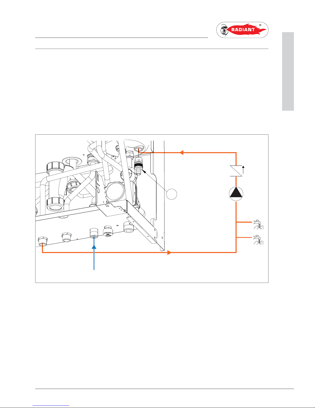
1.1.10. D.H.W. CIRCULATING LOOP
In order to joint the D.H.W out loop pipe, proceed as follows:
› unscrew the ½” cap A (fig.1);
› insert a ½” nipple;
› joint the nipple to the D.H.W. circulating pipe.
KEY
RC- D.H.W. CIRCULATING LOOP
VR- NO-RETURN VALVE
C- CIRCULATOR
U- TAPS
F- COLD WATER MAINS
A
RC
F
C
U
VR
fig. 1
16
R2KA 24 /8 - RAD - ING - Manuale - 1507.1
1 Riempimento dell'impianto_MIAH4_R2KA_.8_EN
1. INSTALLATION
INSTALLER
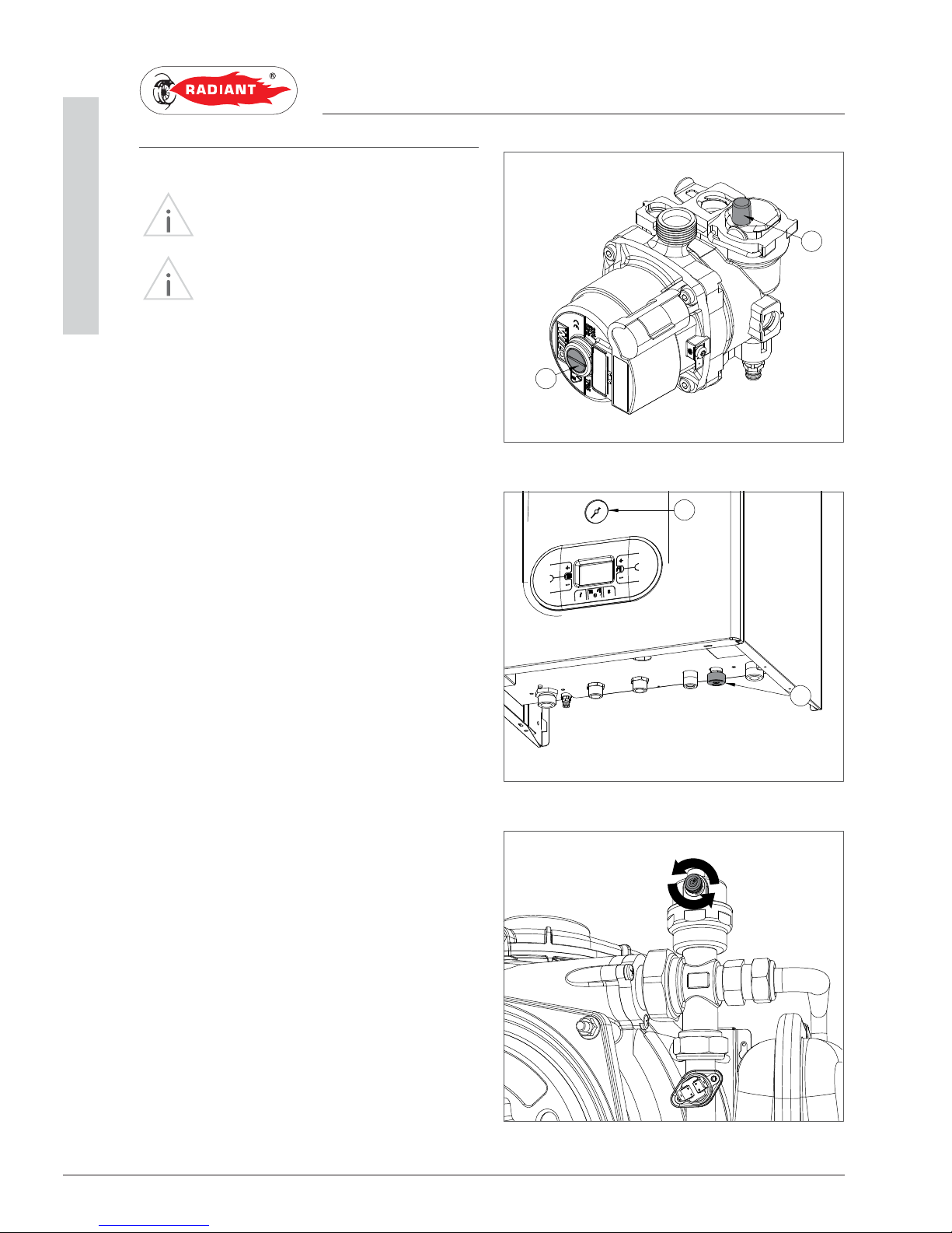
1.1.11. SYSTEM FILLING
WARNING
For system filling use only clean tap water.
WARNING
If the system is filled by adding ethylene
glycol-type chemical agents you have to install on
the loading system a hydraulic trip unit in order to
separate the heating circuit from the domestic circuit.
Before powering up the boiler, fill the system as
follows:
1. Make sure the circulator is not blocked;
2. slightly loosen the cap of the circulator jolly
valve (1-fig. 1) to release the air from the
system;
3. slightly loosen the cap of the jolly valve placed
on the top of the condensing block (fig. 3) to
release the air form the top of the system;
4. open the feeding tap “R” (fig. 2);
5. release all the air;
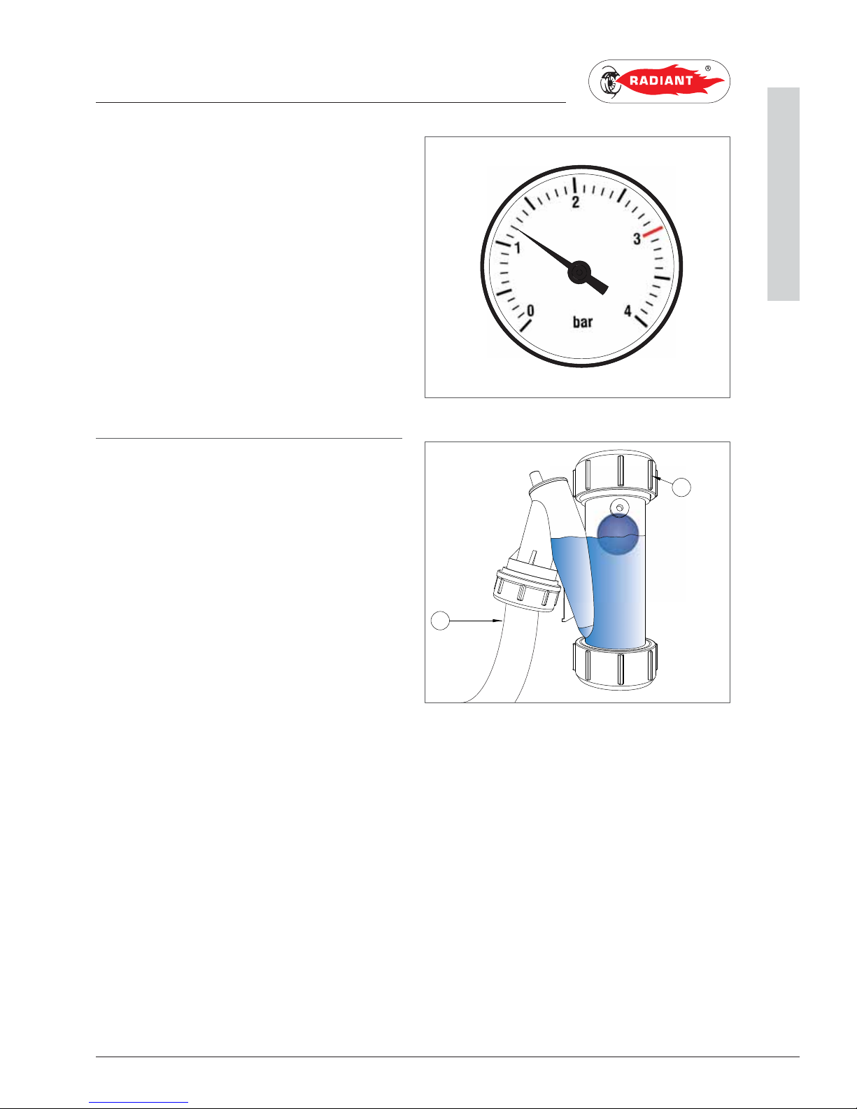
6. use pressure gauge “M” (fig. 2) to make sure
that the system pressure reaches 1.2 bar (fig.
4);
7. after performing this operation, make sure
that the loading tap “R” (fig. 2) is properly
closed.
2
1
M
R
fig. 1
fig. 2
fig. 3
17
R2KA 24 /8 - RAD - ING - Manuale - 1507.1
1 Riempimento dell'impianto_MIAH4_R2KA_.8_EN
1. INSTALLATION
INSTALLER
8. unscrew the circulator cap (2-fig.1) to release
any air bubbles and close it to prevent water
leakage;
9. open the air relief valves of the radiators and
check the air removal process. When the
water starts to leak close the radiators air
relief valves.
10. if after performing these operations you
observe a decrease of the water pressure
inside the system, open once again the loading
tap “R” until the pressure gauge indicates the
value of 1.2 bar (fig. 4)
1.1.12. FILLING THE CONDENSATE
COLLECTION SIPHON
Before starting the boiler you have to fill the
condensate collection siphon in order to avoid fuel
reflux through the siphon.
Fill the condensate collection siphon as follows
(see fig. 5):
› Unscrew the “T” cap from the siphon, fill three
quarters of the the siphon with water and screw
the “T” cap back in;
› Connect the dedicated flexible condensate
draining tube “P” (UNI EN 677) to a waste
disposal system. The condensate can be drained
directly in the sewerage system by inserting an
easily serviceable siphon.
P
T
fig. 4
fig. 5

18
R2KA 24 /8 - RAD - ING - Manuale - 1507.1
1 Protezione antigelo_EN
1. INSTALLATION
INSTALLER
1.1.13. ANTI-FREEZE PROTECTION
The boiler is protected against freezing thanks to
the electronic board preparation with functions
that start the burner and heat the concerned parts
when their temperature goes below the minimum
pre-set values, protecting the boiler up to an
external temperature of -10 °C.
The device starts when the hot water temperature
goes below 5 °C, automatically starting the burner
until the water reaches the temperature of 30 °C.
The system starts even if on the display appears
“OFF”, as long as the boiler is connected to the
power (230 V) and gas supply.
For long periods of standby, please empty the
boiler and the plant.
If the temperature goes below -10° centigrades,
please fill the plant with anti-freeze liquid
(CLEANPASS FLUIDO AG cod. 98716LA) and insert
and electrical resistances kit (cod. 82259LP).

19
R2KA 24 /8 - RAD - ING - Manuale - 1507.1
1 Allacciamento gas_elettrico_MIAH4_EN
1. INSTALLATION
INSTALLER
1.1.14. GAS CONNECTION
DANGER
In order to connect the gas connector of
the boiler to the supply pipe use a stop seal of an
appropriate size and material. The use of hemp,
teflon tape or similar materials is strictly forbidden.
BEFORE PERFORMING THE GAS CONNECTION,
MAKE SURE THAT:
› the gas adduction line complies with the
standards and regulations in force (UNI-CIG
7129/01 – D.M. 12.04.1996);
› the tubing's section suits the requested capacity
and its length;
› the tubing is equipped with all safety and control
devices required by the standards in force;
› the internal and external seals of the gas infeed
plant are checked;
› the device is suitable for use with the type of
gas available by checking the boiler data plate
(placed on the inner side of the front casing. If
they do not match you must take the necessary
measures to adapt the boiler to another type of
gas (see chapter GAS TRANSFORMATION);
› the gas supply pressure falls within the values
indicated on the data plate.
1.1.15. ELECTRICAL CONNECTION
DANGER
The equipment is electrically safe only
if it is properly connected to an efficient grounding
system, performed in compliance with the safety
standards in force (STANDARDS CEI 64-8 and 64-9
Electrical Section). You should check this essential
safety requirement. If in doubt, request an accurate
check of the electrical system performed by qualified
staff, as the manufacturer is not responsible for any
damages caused by lack of grounding system.
› Make sure that the electrical systems is
suitable for the maximum power absorbed by
the equipment, value indicated on the data plate.
› make sure that the cables section is appropriate
for the maximum power absorbed by the
equipment and that it is however not lower than
1 mm
2
.
› The equipment works with alternating current
of 230 V and 50 Hz. The electrical connection
must be performed using an all-pole switch with
an opening of at least 3 millimetres between
contacts placed upstream from the device.
WARNING
Make sure that the phase and neutral
cables connection is performed in compliance with
the wiring diagram (see chapter POWER SUPPLY).
WARNING
It is strictly forbidden the use of adaptors,
multiple plugs and/or extensions for the general
power supply of the equipment from the electrical
network.
20
R2KA 24 /8 - RAD - ING - Manuale - 1507.1
1 Alimentazione elettrica_EN
1. INSTALLATION
INSTALLER
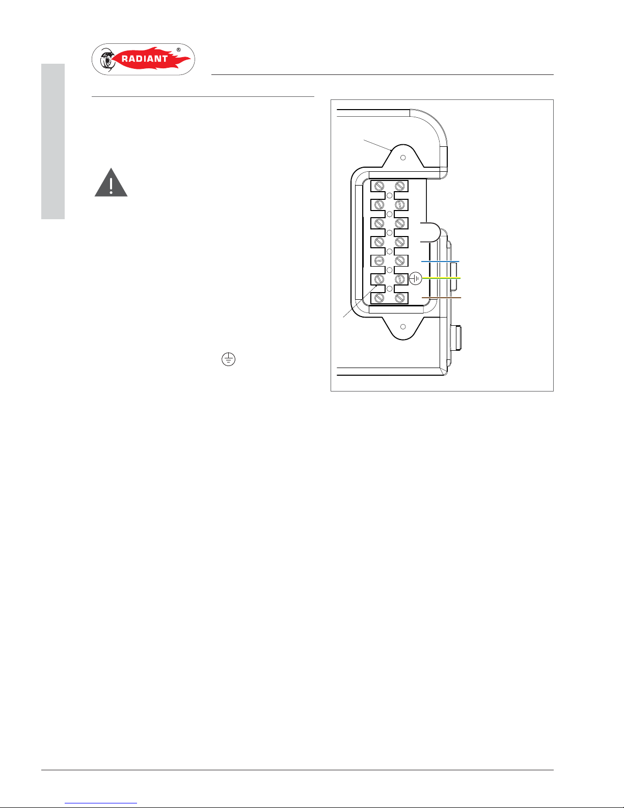
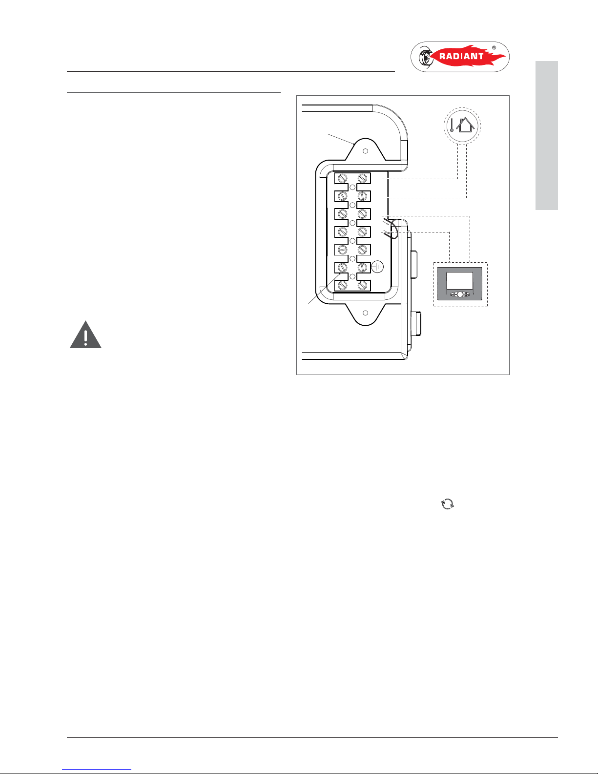
1.1.16. POWER SUPPLY
To power the boiler connect the electrical cables
to the terminal inside the control panel as follows:
DANGER
Cut off the voltage from the main switch.
› remove the boiler's front casing (refer to chapter
ACCESSING THE BOILER).
› loosen the two screws and remove the plate “A”
(see fig. 1).
› after removing the plate, connect the electrical
cables to terminal “B” (see fig. 1):
· the yellow/green cable to the terminal marked
with grounding symbol “
”.
· the blue cable to the terminal marked with
“N”.
· the brown cable to the terminal marked with
“L”.
After performing these operations, remount plate
“A” and the front casing.
L
N
SeSe
A
TaTa
B
BLUE
YELLOW/GREEN
BROWN
fig. 1
21
R2KA 24 /8 - RAD - ING - Manuale - 1507.1
1 Collegamenti elettrici opzionali_SE _TA_CR_MIA H4_EN
1. INSTALLATION
INSTALLER
1.1.17. OPTIONAL ELECTRICAL
CONNECTIONS
To wire the optionals below:
(SE) EXTERNAL TEMPERATURE PROBE COD.
73518LA
(TA) ENVIRONMENT THERMOSTAT
(CR) REMOTE CONTROL OPEN THERM COD. 40-
00017
use the terminal placed inside the control panel
as follows:
DANGER
Cut off the voltage from the main switch.
› remove the front casing of the boiler (see
chapter ACCESSING THE BOILER); unscrew the
screws and remove plate “A” (see fig. 1).
› After removing the plate, connect the electrical
cables to terminal “B” (see fig. 1):
· For the external temperature Probe connect
the two non-polarized conductors to the SeSe contacts.
· For the environment Thermostat or Remote
control, first remove the bridge on the TaTa contacts and then connect the two nonpolarized conductors to the Ta-Ta contacts.
After performing these operations, remount plate
“A” and the front casing.
NB: In case of simultaneous presence of external probe and
remote control, the modulation board only sends the external
temperature value to the remote device without using it for
modulation.
The communication between board and remote control takes
place independently from the boiler's operating mode and after
establishing the connection, the used interface on the board is
disabled and the display shows the symbol ‘
’.
L
N
SeSe
A
TaTa
B
SE
TA
CR
fig. 1
22
R2KA 24 /8 - RAD - ING - Manuale - 1507.1
1 Collegamenti elettrici opzionali_ MIA H4 _EN
1. INSTALLATION
INSTALLER
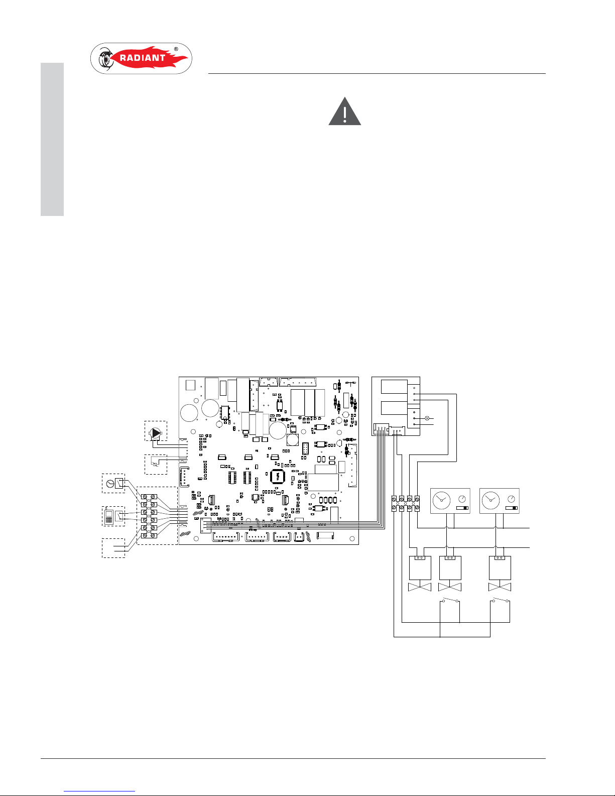
To wire the optionals below:
FCCE:KB7J?D=FKCF
JF :EC;IJ?9 >EJ M7J;H FH;#>;7J?D=
:;79J?L7J?EDJ?C;H
9JJ;B;F>ED;:?7B;H
8KI&#'&L
ILP 9EDJHEB 8E7H: <EH 7H;7 L7BL;I
9EDD;9J;: JE 7 H;CEJ; 9EDJHEB 9E:$ ,+#
&&&)&
use the electronic board placed inside the control
panel as follows:
:7D=;H
Cut off the voltage from the main switch.
› remove the boiler's front casing (refer to chapter
ACCESSING THE BOILER).
› remove the crankcase of the control panel
(see chapter ACCESSING THE ELECTRONIC
BOARD).
› after removing the crankcase, connect the
items below to the electronic board (see fig. 1):
After performing these operations, remount the
crankcase and the front casing.
TP
CT
BUS 0-10V
GND
BUS+
11
10
98
7
12
13
14
15
16
17
M12
M9
M7
M5
M2
M4
M8
M10
M15
M16
1
2
3
4
57
61
60
59
58
4443424140
39
38
3736353433
32
31
30
29
28
27
26
MIAH4
ce
ma
PM
SR
62
63
64
65
66
67
68
51
52
53
54
55
56
5
6
M13
M14
ar
ar
ne
ne
ce
ma
220 V - 50 Hz
L
N
VZR
VZ2 VZ1
FC FC
TAZ 2
TAZ 1
SRB
N
1
2
3
4
5
6
98
7
M1
M4
M2
M3
SVZ
L
gr
ar
ro
ne
COD.40-00133
fig. 1
SR: RETURN PROBE FC: ARE A VALVES LIMIT SWITCH
SRB: REMOTE LED FOR SIGNALLING BOILER BLOCK GR: GREY
TAZ1: ENVIRONMENT THERMOSTAT AREA 1 AR: ORANGE
TAZ 2: ENVIRONMENT THERMOSTAT AREA 2 NE: BL ACK
VZ1: AREA 1 VALVE MA: BROWN
VZ2: AREA 2 VALVE CE: LIGHT BLUE
VZR: REMOTE CONTROLLED AREA VALVE RO: RED

23
R2KA 24 /8 - RAD - ING - Manuale - 1507.1
1 Raccordi fumari_cond_EN
1. INSTALLATION
INSTALLER
1.1.18. FUME EXHAUST FITTINGS
WARNING
In order to ensure proper operation and
efficiency of the device you have to connect the boiler
fume exhaust fitting to the fume exhaust duct using
appropriate polypropylene flue fittings for condensing
boilers. It is recommended to install discharge
systems approved by Radiant.
WARNING
You cannot use traditional flue fittings for
the discharge ducts of the condensing boilers, nor
vice versa.
WARNING
For fumes exhaust and condensate
collection, please follow standard UNI 11071.
› For all discharge ducts, with regard to the
fumes path, you should provide an uphill slope
(outwards) so as to favour the reflux of the
condensate towards the combustion chamber,
suitably realized to collect and drain acid
condensate.
› For all air suction ducts, with regard to the air
path, you should provide an uphill slope (towards
the boiler) so as to avoid the protrusion inside
the duct of rain water, dust or foreign objects.
› If a vertical fumes duct is installed, insert a
condensate collection siphon at the base of the
duct connected to the sewerage system of the
location (fig. 1).
› In case of horizontal co-axial system installation,
correctly place the horizontal co-axial terminal
suitably realized to respect the slopes inside the
fumes duct and to protect the air suction duct
from adverse weather conditions.
› In order to discharge the fumes through a fumes
exhaust duct carefully follow the technical
standards in force (for example UNI 10641 and
UNI EN 13384).
› Make sure that the discharge tube doe not
protrude inside the fumes exhaust duct, stop
before it reaches the inner surface of the latter.
› The discharge duct must be perpendicular with
the opposite internal wall of the chimney or of
the fumes exhaust duct (fig. 2).
fig. 1
fig. 2
 Loading...