

Page 1

Installation, Use
and Maintenance Manual
for model
R1K 50
Premix condensing system boiler
only heating
0476
R1K 50 - RAD - ING - Manuale - 1801.1_SK.3
Page 2
SUMMARY
SUMMARY
INTRODUCTION 4
1. INSTALLER SECTION 7
1.1. INSTALLATION 8
1.1.1. GENER A L INS TALLATION WARNINGS 8
1.1.2. BOILER LOCATION ENVIRONMENTAL REQUIREMENTS 8
1.1.3. REFERENCE LEGISL ATION 9
1.1.4. BOILER OVERALL DIMENSIONS 10
1.1.5. JIG 10
1.1.6. OVERALL DIMENSIONS OF THE HEATING ONLY MODULE 10
1.1.7. OVERALL DIMENSIONS OF THE MODULE FOR REMOTE BOILER SUPPLY 11
1.1.8. MECHANICAL SYSTEM DIAGRAM 12
1.1.9. SYSTEM ACCES SORIES 14
1.1.10. CIRCULATOR PREVALENCE/FLOW DIAGRAM 16
1.1.11. GENERATOR INSTAL L ATION 17
1.1.12. HYDRAULIC CONNECTION 20
1.1.13. CHARACTERISTICS OF THE WATER OF THE SYSTEM 21
1.1.14. SYSTEM FILLING 23
1.1.15. FILLING THE CONDENSATE COLLECTION SIPHON 24
1.1.16. ANTI-FREEZE PROTECTION 25
1.1.17. GAS CONNECTION 26
1.1.18. ELECTRICA L CONNECTION 26
1.1.19. POWER SUPPLY 27
1.1.20. OPTIONAL ELECTRICAL CONNECTIONS 28
1.1.21. FUME EXHAUST FITTINGS 31
1.1.22. T YPES OF FUME EXHAUST SYSTEMS 32
R1K 50_EN
2. SUPPORT CENTER SECTION 37
2.1. FIRST START-UP 38
2.1.1. PRELIMINARY OPERATIONS FOR FIRST START-UP 38
2.1.2. BOILER COMMISSIONING 39
2.1.3. CO2 VALUE CHECK AND CALIBRATION 40
2.1.3. ACCESSING AND PROGRAMMING THE PARAMETERS 41
2.1.4. DIGITECH CS PARAMETERS TABLE 43
2.1.6. ELECTRIC FAN FREQUENCY/HEAT CAPACITY DIAGRAM 50
2.2. MAINTENANCE 51
2.2.5. GENERAL MAINTENANCE WARNINGS 51
2.2.8. TECHNICAL DATA 52
2.2.9. TECHNICAL ASSEMBLY 54
2
R1K 50 - RAD - ING - Manuale - 1801.1_SK.3
Page 3
SUMMARY
2.2.6. HYDRAULIC BOARD 55
2.2.7. WIRING DIAGRAM 56
2.2.13. ACCESSING THE BOILER 57
2.2.8. ACCESSING THE ELECTRONIC BOARD 58
2.2.16. SYSTEM EMPTYING 59
2.2.9. FAULT SIGNALLING CODES 60
2.2.10. ACTIVE FUNCTIONS SIGNALLING CODES 63
2.2.11. GAS CONVERSION 64
3. USER SECTION 65
3.1. USE 66
3.1.1. GENERAL USE WARNINGS 66
3.1.2. CONTROL PANEL 67
3.1.3. DISPLAY ICONS 68
3.1.4. INFO MENU DISPLAY DATA 69
3.1.5. START-UP 70
3.1.6. OPERATING MODE 70
3.1.7. INFORMATIONAL NOTE ON ANTI-FREEZE FUNCTION 71
3.1.8. FAULT SIGNALLING CODES 72
3.1.9. ACTIVE FUNCTIONS SIGNALLING CODES 74
R1K 50_EN
3
R1K 50 - RAD - ING - Manuale - 1801.1_SK.3
Page 4
INTRODUCTION
1.
INTRODUCTION
WARNING
Before starting any operation it is mandatory to
read this instruction manual, in relation to the
activities to be carried out as described in each
relevant section. Proper operation and optimal
performance of the boiler are ensured by strict
compliance with all the instructions given in this
manual.
The installation, use and maintenance manual is
an integral and essential part of the product and
must be delivered to the user.
MANUAL USERS
The manual users are all those who install, use
and maintain the boiler.
The boiler must be used and accessed only by
qualified operators that fully read and understood
the use and maintenance manual, paying par ticular
attention to the warnings.
READING AND SYMBOLS OF THE MANUAL
To ease the understanding of this manual,
recurrent symbols where used, in particular:
› On the outer margin of the page is placed a
thumb index indicating the type of user to which
the instructions in that section address.
DANGER
It identifies an information related to a
general danger that if not complied with, may cause
serious personal damage or even death.
ATTENTION
It identifies an information that if not
complied with may cause small or medium level
lesions to the person or serious deterioration to the
boiler.
WARNING
It identifies a precaution information that
must be observed in order to avoid damaging the
machine or parts of it.
MANUAL STORAGE
The manual must be carefully stored and replaced
in case of deterioration and/or low legibility.
If you misplace the use and maintenance manual,
you can request it from the Technical Support
Centre giving the serial number and model of the
boiler indicated on the plate placed on the right
side of its casing.
As an alternative, the use and maintenance manual
can be downloaded free from the on-line site www.
radiant.it, accessing the “download” section and
entering the boiler model.
_Prefazione_EN
› The titles are differentiated by thickness and
size in accordance with their hierarchy.
› The images contain important parts described
in the text, marked with numbers or letters.
› (See chap “chapter name”): this entry indicates
another section in the Manual that you should
refer to.
› Device: this term is used referring to the boiler.
4
R1K 50 - RAD - ING - Manuale - 1801.1_SK.3
Page 5

INTRODUCTION
1 .
MANUFACTURER WARRANTY AND
RESPONSIBILITY
The warranty of the Manufacturer is provided only
through its own authorized Technical Support
Centres, listed for each Region and Provence on
the site www.radiant.it, and covers all conformity
defects at the moment of sale.
The technical and functional features of the device
are ensured by its use in compliance:
1. with the use and maintenance instructions
contained in the manuals accompanying the
product, the content of which the customer
certifies that he is aware;
2. with the conditions and purposes to which
assets of the same type are intended.
For more information on the warranty validity,
its duration, the obligations and the exemptions,
please consult the First start-up certificate
attached to this manual.
› Energy labeling Directive 2010/30/CE,
› EU regulation 811/2013,
› EU regulation 813/2013,
› Gas Directive 2016/426/EU,
› Electromagnetic compatibility Directive
2014/30/CE,
› Performance Directive 92/42/CE,
› Low voltage Directive 2014/35/CE.
The materials used such as copper, brass,
stainless steel create a homogeneous, compact
and functional assembly, easy to install and
manage. In its simplicity, the boiler is equipped
with all accessories necessary to render it a
veritable independent heating unit. All boilers
are tested and delivered with a quality certificate
signed by the tester.
_Prefazione_EN
The manufacturer reserves:
› the right to modify the tools and relative
technical documentation without any obligation
to third parties; neither will the company be
held responsible for any inaccuracies in this
handbook deriving from printing or translation
errors;
› the material and intellectual ownership of
this manual and forbids its distribution and
duplication, even partial, without prior written
authorization.
PRODUCT CONFORMITY
RADIANT BRUCIATORI spa declares that its gas
boilers comply with the European Directives and
with the requirements provided in the European
standards below:
› Eco-design Directive 2009/125 CE,
5
R1K 50 - RAD - ING - Manuale - 1801.1_SK.3
Page 6

Page 7

1. INSTALLER SECTION1. INSTALLER SECTION
The installation operations described in this section should
be performed only by qualified personnel, having the
appropriate technical training in the field for the installation
and maintenance of components of civil and industrial
domestic hot water production and heating plants.
Page 8
INSTALLER
1.1. INSTALLATION
2. INSTALLATION
1.1.1. GENERAL INSTALL ATION
WARNINGS
ATTENTION
This machine may be used only for the
purpose for which it has been designed: heat water
to a temperature below boiling point at atmospheric
pressure. Any other use is considered wrong and
dangerous. The manufacturer is excluded from
any contractual or out of contract responsibility for
damage caused to people, animals or property due
to errors during installation.
ATTENTION
This boiler should be installed only
by qualified personnel, having the appropriate
technical training in the field for the installation and
maintenance of components of civil and industrial
domestic hot water production and heating plants.
ATTENTION
After having removed the packing, make
sure the equipment is intact. In case of doubt, do not
use the equipment and contact the supplier.
BEFORE INSTALLING THE BOILER, THE
INSTALLER MUST MAKE SURE THAT THE
FOLLOWING CONDITIONS ARE MET:
› The device is connected to a heating plant and a
water supply network appropriate for its power
and performance.
› The location must be properly vented through
an air vent.
› The air vent must be placed at floor level to
prevent it from being obstructed, protected by
a grid that does not hamper the useful section
of passage.
› The device is suitable for use with the type of
gas available by checking the boiler data plate
(placed on the inner side of the front casing.
› Make sure that the tubes and couplings are
perfectly sealed, without any gas leaks.
› Make sure that the grounding system works
properly.
› Make sure that the electrical systems is
suitable for the maximum power absorbed by
the equipment, value indicated on the data plate.
WARNING
Use only original RADIANT optional or kit
accessories (including electrical).
1.1.2. BOILER LOCATION
ENVIRONMENTAL
REQUIREMENTS
The boiler has a thermal power over 35 kW and,
therefore, it must be installed only into a heating
unit.
The device's installation location should be vented
due to the presence of threaded joints on the gas
adduction line. The location should be therefore
provided with vents as to ensure air exchange,
with output grid in the natural accumulation area
of eventual gas losses.
WARNING
DO NOT install the boiler in a technical
compartment near a swimming pool or a laundry, to
avoid that the combustion air is exposed to chlorine,
ammonia or alkaline agents that may worsen the
corrosion phenomenon of the heat exchanger. Failure
to observe this caution will void the warranty of the
heat exchanger.
1 Avvertenze gener ali per l'installazione_Locale c aldaia _cond _ alta potenza_EN
8
R1K 50 - RAD - ING - Manuale - 1801.1_SK.3
Page 9
WARNING
If the temperature in the boiler installation
location goes below -10 centigrades, please fill
the plant with anti-freeze liquid and insert and
electrical resistances kit (see chapter ‘ANTI-FREEZE
PROTECTION’).
WARNING
The manufacturer will not be held
responsible for damages caused by incorrect
installation not in conformity with the over mentioned
instructions and not protected adequately from the
freeze.
1.1.3. REFERENCE LEGISLATION
The installation must be realized according to
the requirements of current legislation and in
compliance with local technical regulations,
according to the indications of the good technique.
2. INSTALLATION
INSTALLER
1 Avvertenze gener ali per l'installazione_Locale c aldaia _cond _ alta potenza_EN
9
R1K 50 - RAD - ING - Manuale - 1801.1_SK.3
Page 10
INSTALLER
3. INSTALLATION
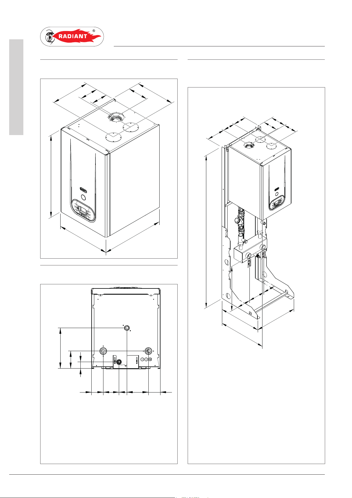
1.1.4. BOILER OVERALL DIMENSIONS
302
157
480
640
306
150
136
410
1.1.6. OVERALL DIMENSIONS OF THE
HEATING ONLY MODULE
160
145
209
1794
178
192
155
1.1.5. JIG
244
R- HEATING RETURN Ø 1” 1/4
G- GAS Ø 3/4
A- HEATING FLOW Ø 1” 1/4
SC- CONDENSATE DRAIN Ø 25 mm
107
42
70 94 47 129 70
RGsc A
157
530
157
157
504
524
524
RI RETURN SYSTEM Ø 1”1/2
AI DELIVERY SYSTEM Ø 1”1/2
157
200
514
1 Dimensioni_R1K 50_no INAIL_EN
10
R1K 50 - RAD - ING - Manuale - 1801.1_SK.3
Page 11

1.1.7. OVERALL DIMENSIONS OF THE
MODULE FOR REMOTE BOILER
SUPPLY
3. INSTALLATION
INSTALLER
209
1794
145
227 99227 99282282
160
178
192
155
1 Dimensioni_R1K 50_no INAIL_EN
157
157
200
157
157
504
524524
RI RETURN SYSTEM Ø 1”1/2
AI DELIVERY SYSTEM Ø 1”1/2
RB HEATING FLOW TO DHW
STORAGE CYLINDER
AB HEATING FLOW TO DHW
STORAGE CYLINDER
514
Ø 1”
Ø 1”
R1K 50 - RAD - ING - Manuale - 1801.1_SK.3
11
Page 12
INSTALLER
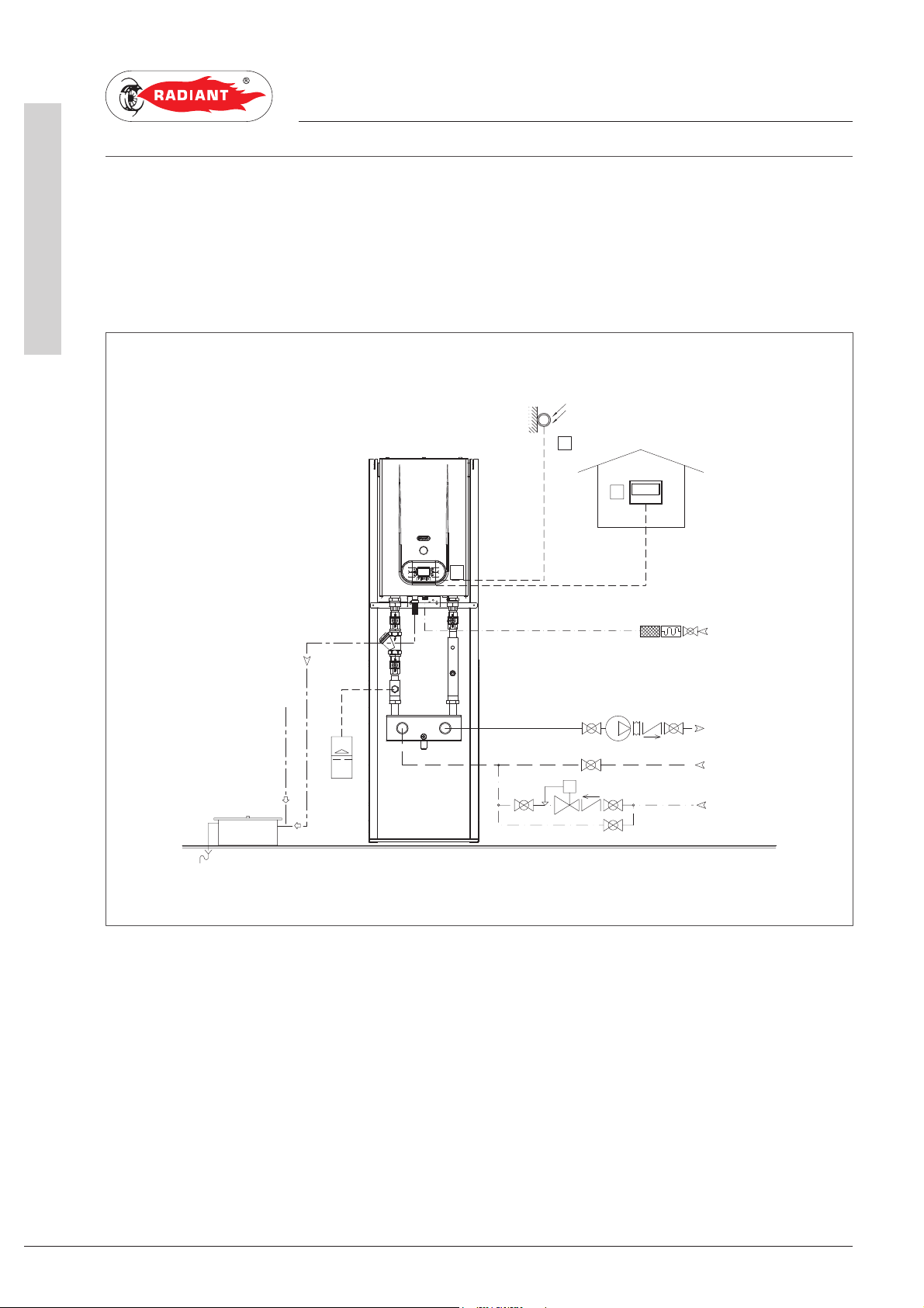
1.1.8. MECHANICAL SYSTEM DIAGRAM
HEATING ONLY INSTALLATION
The boiler can manage a heating system at a fixed point delivery temperature or in climatic compensation
with an external probe, managing the modulation according to the actually requested thermal load.
1. INSTALLATION
1
2
fume exhaust system
3
GAS
DELIVERY
SYSTEM
RETURN
SYSTEM
condensate
LOAD
SYSTEM
1 Schema meccanico impianto_R1K 50_no INAIL _EN
12
DESCRIPTION
1 EXTERNAL PROBE
2 REMOTE OPEN THERM
3CONTROL PANEL
R1K 50 - RAD - ING - Manuale - 1801.1_SK.3
Page 13
1. INSTALL ATION
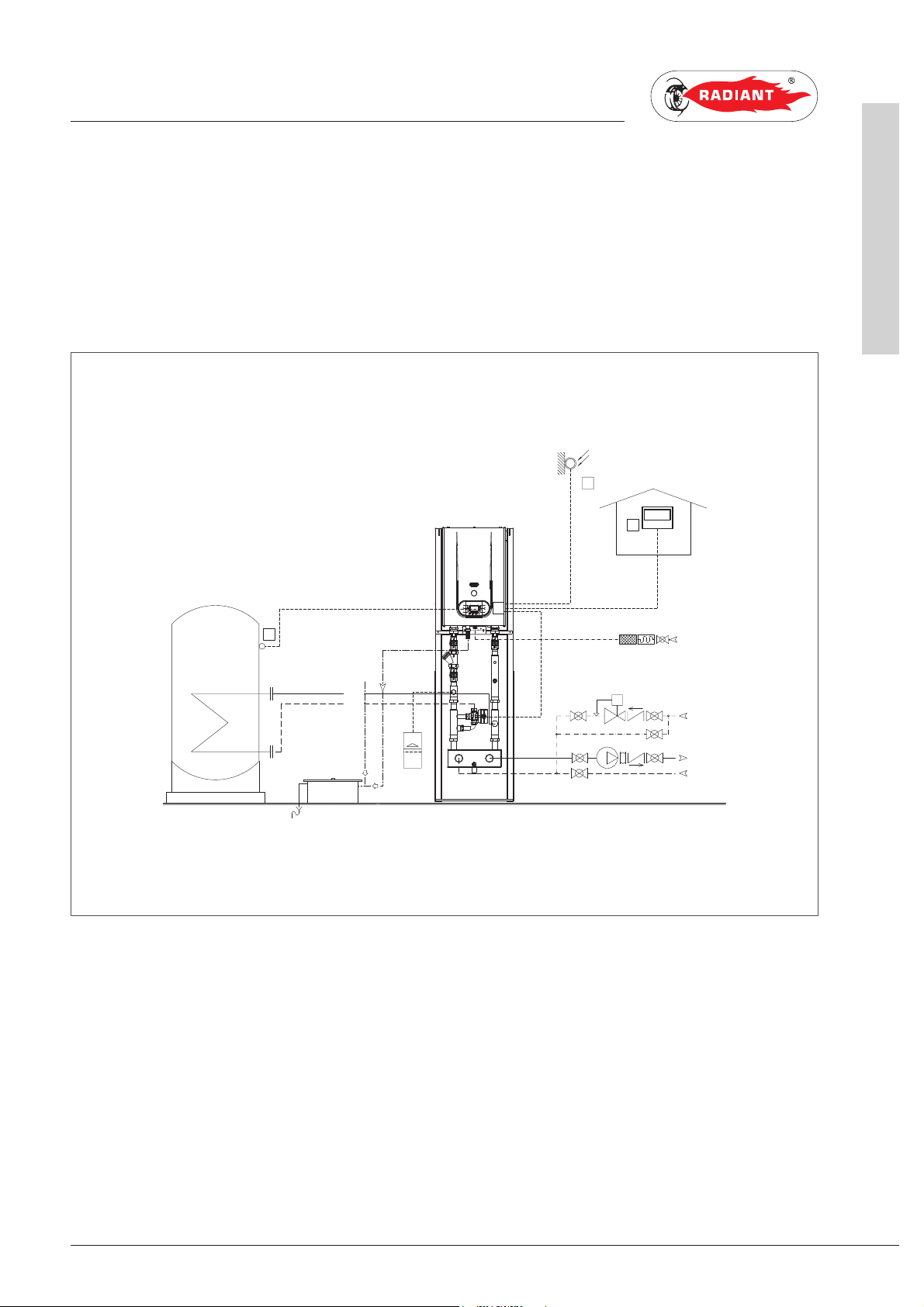
HEATING INSTALLATION + REMOTE BOILER SUPPLY SYSTEM
The boiler can manage a heating system at a fixed point delivery temperature or in climatic compensation
with an external probe, managing the modulation according to the actually requested thermal load.
The boiler probe activates the system in order to pre-heat the boiler, the boiler will be put into domestic
circuit mode and the deviating valve switches to the remote boiler.
1
2
INSTALLER
1 Schema meccanico impianto_R1K 50_no INAIL _EN
4
DESCRIPTION
1 EXTERNAL PROBE
2 REMOTE OPEN THERM
3CONTROL PANEL
4 REMOTE BOILER NTC PROBE
fume exhaust system
condensation
3
GAS
LOAD SYSTEM
DELIVERY SYSTEM
RETURN SYSTEM
R1K 50 - RAD - ING - Manuale - 1801.1_SK.3
13
Page 14
INSTALLER
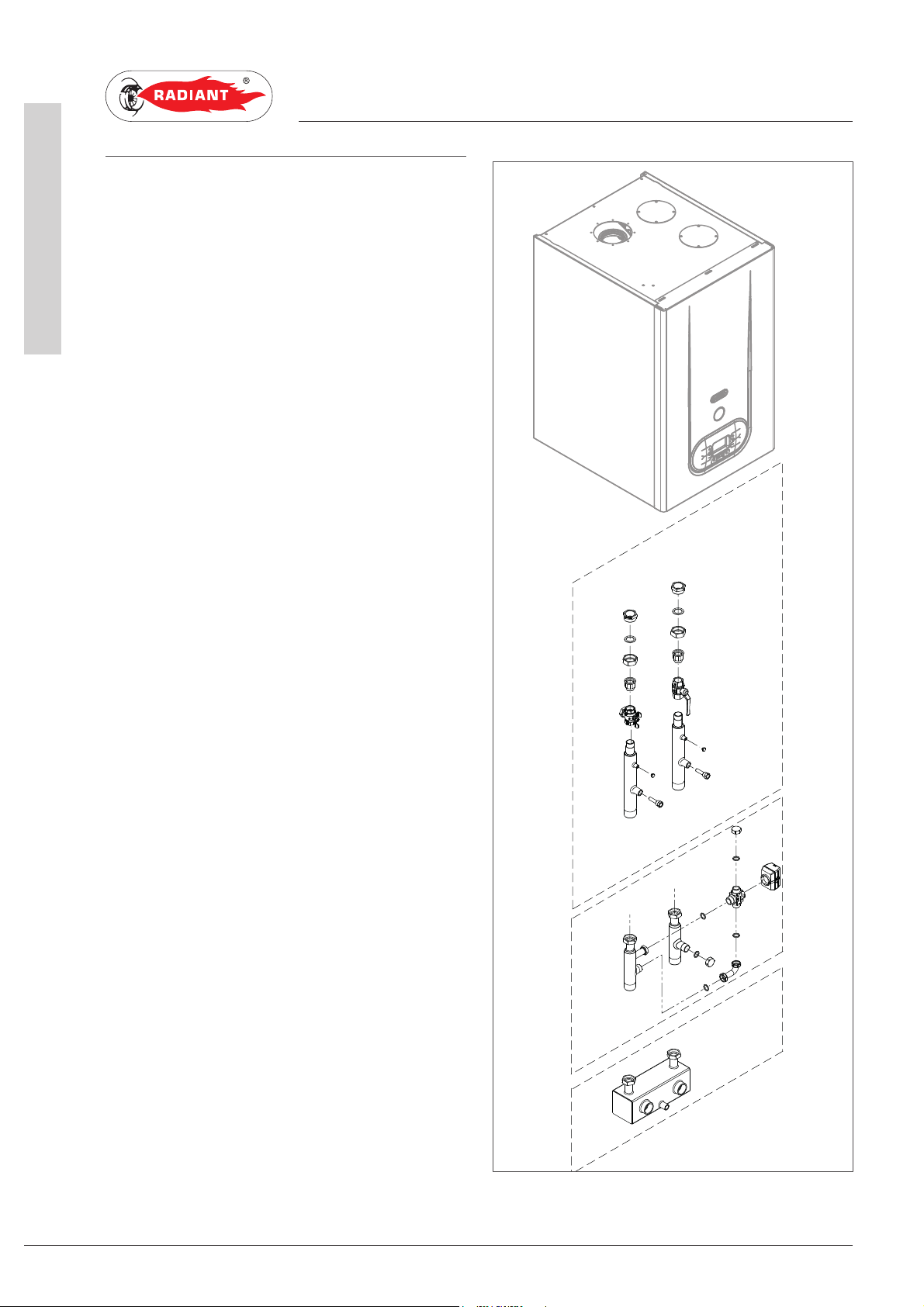
1.1.9. SYSTEM ACCESSORIES
DIVERTER VALVE KIT
The kit allows combining the thermal generator
with a remote boiler for the production of domestic
hot water (cod. 26097LP, fig. 1).
In this configuration, it is possible to manage the
domestic circuit in an independent manner, by
implementing a diverter valve which ensures the
power supply of the serpentine upon the preheating request of the boiler.
The kit is completed with a probe for the external
boiler and with a power supply cable of the diverter
valve which is connected directly to the electronic
board of the generator.
1. INSTALLATION
HYDRAULIC SEPARATOR
In order to always ensure to the heat generator an
operation without problems related to two low heat
capacities (due, for example, to closed radiators or
to impurities of various type), it is strictly necessary
to install a trip unit, as an alternative, a heat
exchanger which separates the hydraulic circuit.
Choosing a separation system in the detriment of
another is exclusively imposed by the type of the
system.
In case of a new system o r in case of replacem ent of
the generator with the possibility to wash the water
pipes, it is recommended to install a hydraulic
separator (code 26205LA, fig. 1).
The hydraulic separator creates an area with
reduced load loss, which allows hydraulically
rendering independent the primary and secondary
circuits connected to it. With the hydraulic separator
you can thus have a production circuit with constant
heat capacity and a distribution circuit with variable
heat capacity, operation conditions typically specific
to modern air-conditioning systems.
1 Accessori impianto_R1K 50_no INAIL_EN
cod. 26097LPcod. 26205LA cod. 65-00440
fig. 1
14
R1K 50 - RAD - ING - Manuale - 1801.1_SK.3
Page 15

Particular attention should be given, during the
design phase, to possible temperature variations
to which the circuits can be subject due to the
generated mixing inside the hydraulic separator.
A secondary circuit with a heat capacity higher
than the circulatory one of the primary circuit
generates, in fact, by means of the hydraulic
separator, a delivery temperature lower than the
one of the primary circuit.
1. INSTALL ATION
INSTALLER
1 Accessori impianto_R1K 50_no INAIL_EN
15
R1K 50 - RAD - ING - Manuale - 1801.1_SK.3
Page 16
INSTALLER
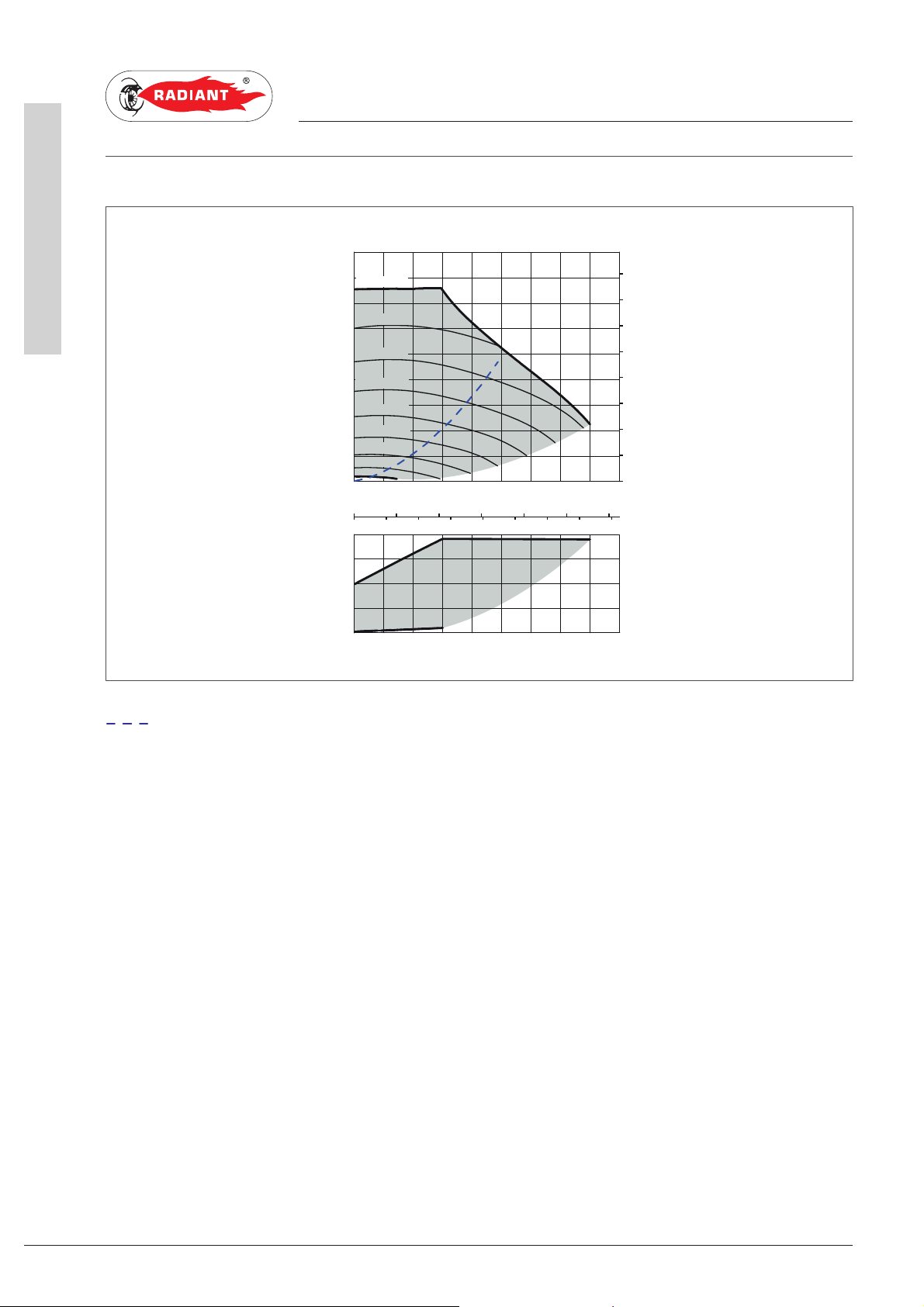
1.1.10. CIRCULATOR PREVALENCE/FLOW DIAGRAM
1. INSTALLATION
Wilo-Yonos PARA RS 15/7.5
H/m
8
PWM1
4770/ 5
7
PWM1
4270/ 15
6
PWM1
5
3780/ 25
4
PWM1
3280/ 35
3
PWM1
2780/ 45
PWM1
2
2280/ 55
PWM1
1780/ 65
1
PWM1
1290/ 75
PWM1
790/ 85
0
PREVALENCE (m)
0 0,5 1,0 1,5 2,0 2,5 3,0 3,5
0 0,2 0,4 0,6 0,8 1,0
20 4 6 8 10 12 14
/W
P
1
60
40
20
0
0 0,5 1,0 1,5 2,0 2,5 3,0 3,5
max.
4,0
4,0
Q/m³/ h
Q/l/s
Q/Igpm
max.
Q/m³/ h
p/kPa
80
70
60
50
40
30
20
10
0
Appliance Loss
FLOW RATE (m3/h)
1 Diagramma portata-prevalenza circol atore _R1K 50_YONOS PARA RS 15-7.5_EN
16
R1K 50 - RAD - ING - Manuale - 1801.1_SK.3
Page 17
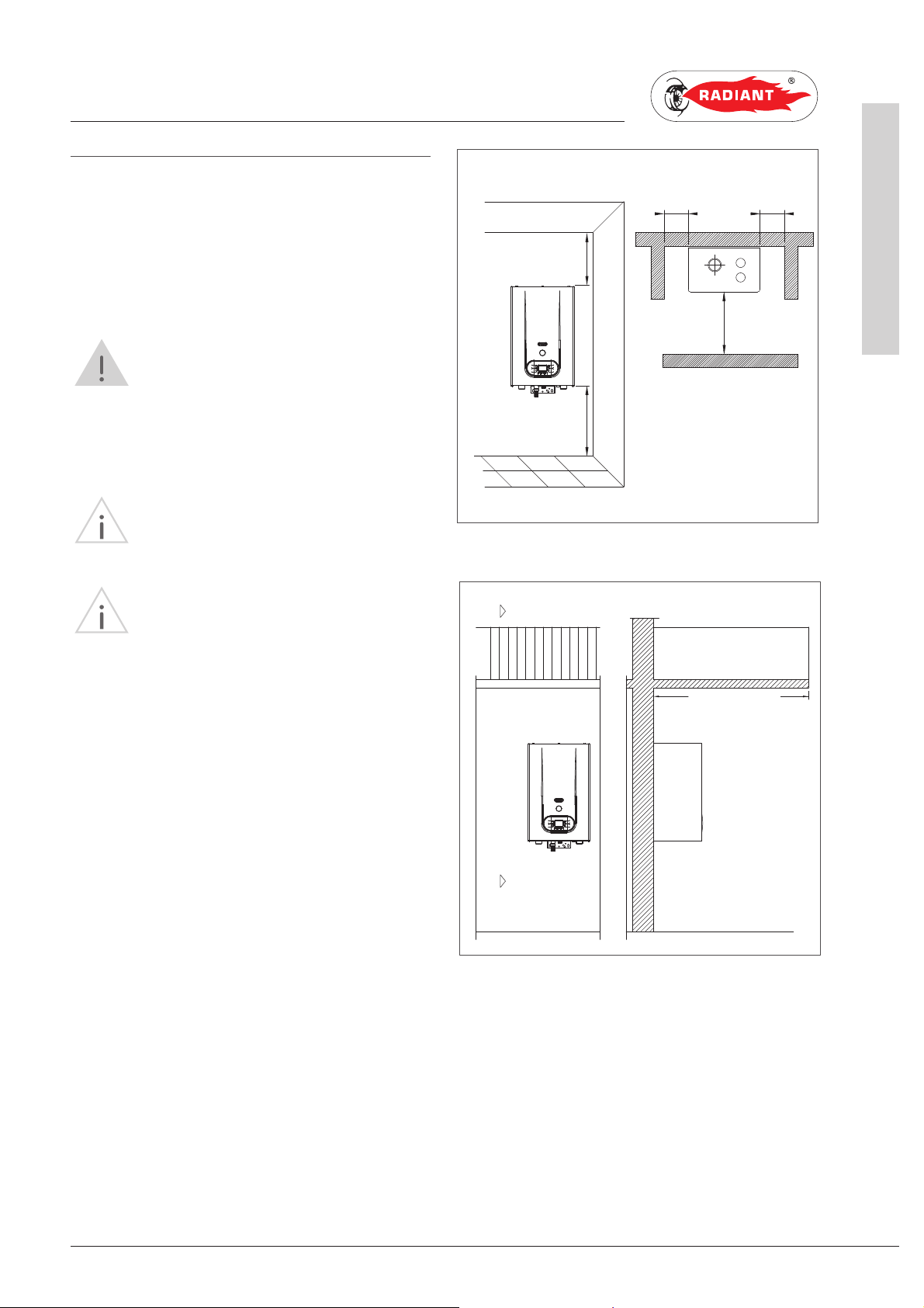
1.1.11. GENERATOR INSTALLATION
MINIMAL TECHNICAL SPACES
1. INSTALL ATION
INSTALLER
X Y
In order to allow the access inside the boiler for
maintenance operations, you have to respect the
minimum technical spaces indicated in figure 1.
WARNING
The incorrect slopes of the device can
cause the incorrect discharge of condensate by
means of the discharge duct with consequent
condensate stagnation inside the condensate
module.
WARNING
The boiler must be installed only on a
vertical solid wall, able to sustain its weight.
WARNING
The boilers have the electrical
protection degree IPX5D. The outdoor installation
in partially protected environments (platform roof,
balcony - see fig. 2) is allowed in compliance with
the related standards. The Company is not held
liable for installations in environments with a
temperature under –10°C or non-compliant with
the above indications.
A
H
B
A
A - 200 mm
B - 300 mm
X - 60 mm
Y - 60 mm
H - 1,000 mm
balcony/ platform roof
1,200 mm minimum
fig.1
A
SECTION A-A
1 Installazione generatore_R1K 50_EN
fig. 2
17
R1K 50 - RAD - ING - Manuale - 1801.1_SK.3
Page 18
INSTALLER
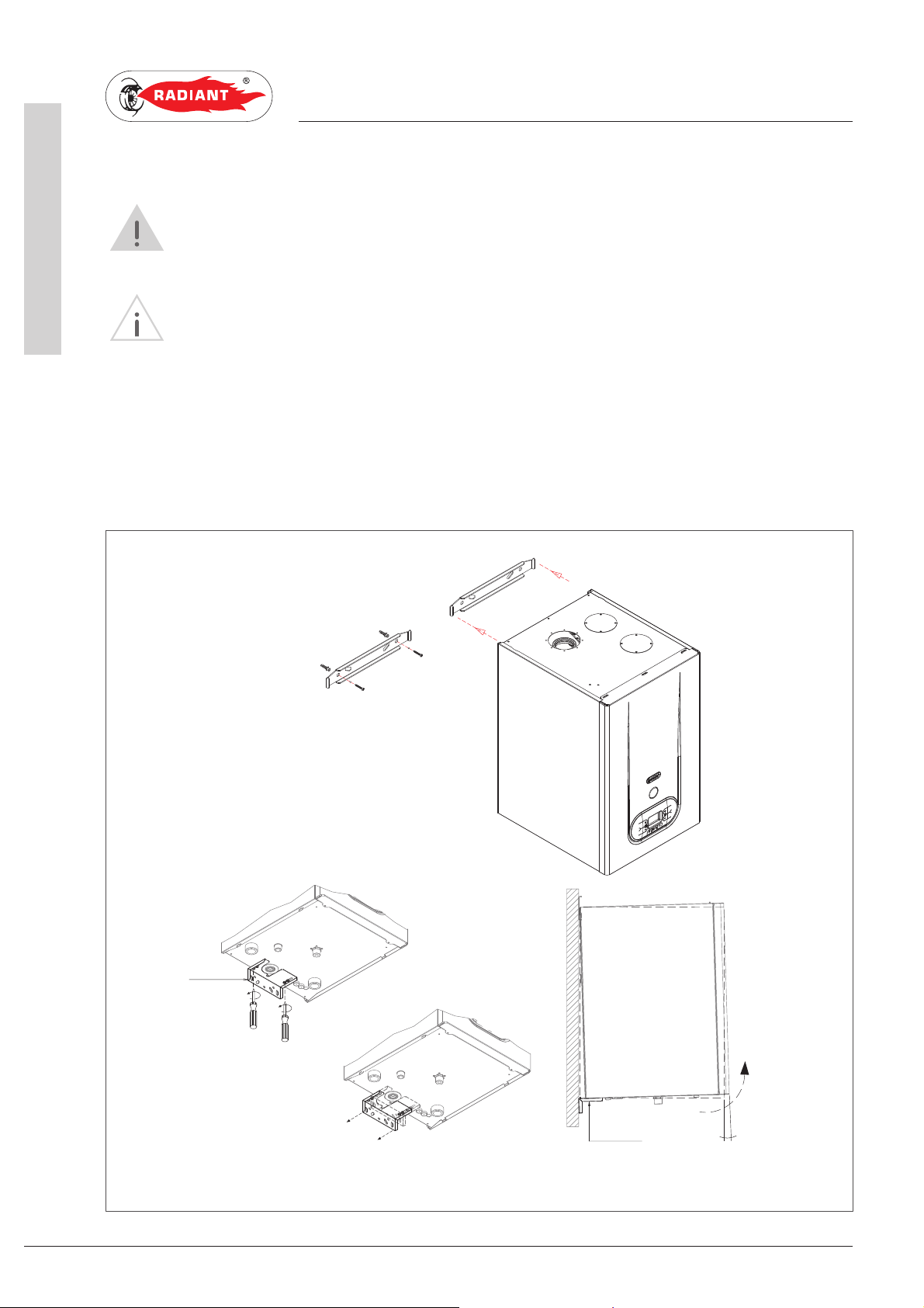
WALL MOUNTING BY MEANS OF FIXING BRACKET
is slightly inclined towards the rear part (1-1.5°) in order to evacuate the condensate.
In order to fix the thermal generator on the wall, proceed as follows:
1. fix on the wall (fig. 1), using the fisher, the upper bracket;
2. hook the eyelets of the boiler into the adequate hooks (fig. 2);
3. unscrew the fixing screws of the lower bracket (fig. 3) ensuring the free sliding of the bracket (fig. 4)
4. adjust the inclination of the boiler (fig. 5) by sliding the lower bracket ensuring an inclination of the
1. INSTALLATION
WARNING
In order to avoid condensate stagnations inside the condensate module, check that the boiler
WARNING
The device must be installed only on a vertical solid wall, able to sustain its weight.
towards the boiler;
boiler, against the vertical, of about 1–1.5°.
LOWER
BRACKET
fig. 3
fig. 2
fig.1
1 Installazione generatore_R1K 50_EN
fig. 5
18
fig. 4
R1K 50 - RAD - ING - Manuale - 1801.1_SK.3
LOWER
BRACKET
1-1.5°
Page 19
1. INSTALL ATION
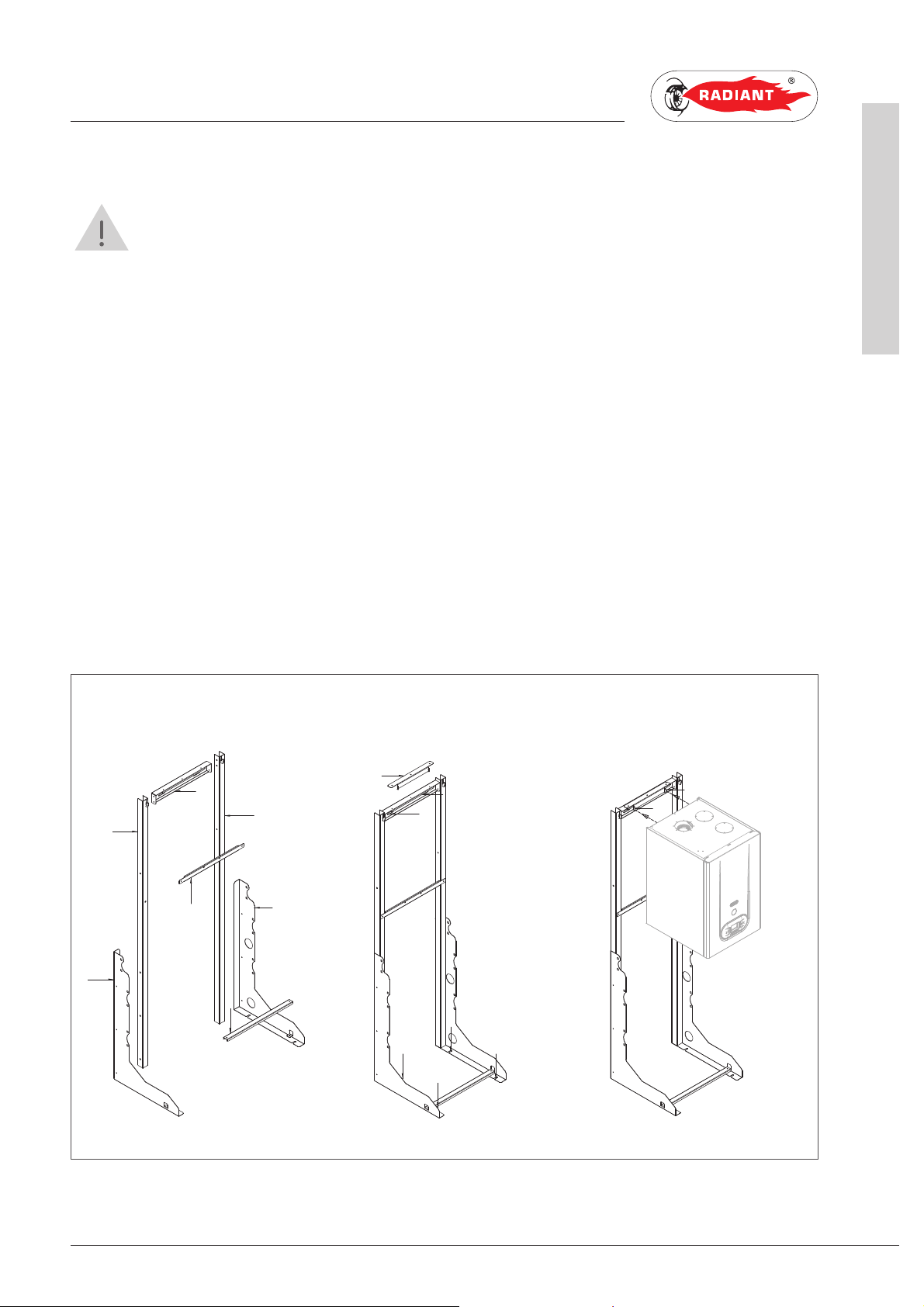
INSTALLATION ON SELF-SUPPORTING FRAME
WARNING
During the installation of the heat generator, pay maximum attention to the installation of the
self-supporting frame. The frame must rest on a perfectly flat surface and, when supported against
the wall, the latter must be perfectly angled. The incorrect slopes of the device can cause the incorrect
discharge of condensate by means of the discharge duct with consequent condensate stagnation inside
the condensate module. The correct installation of the frame allows obtaining, acting on the lower
bracket, a counterslope of the device against the perpendicular.
In order to mount the frame and therefore the generator, proceed as follows:
1. check the angle of the wall with the floor;
2. assemble the side profiles 3 and 4 on the pillars 1 and 2 (fig. 1);
3. assemble the side pillars 1 and 2 on the horizontal crossbeam 5;
4. assemble the central crossbeam 8 and the lower one 7;
5. complete the assembly, position the frame binding it to the wall 9 (if provided) and on the floor 10;
6. mount the upper bracket 6 and hook the eyelets of the boiler into the adequate hooks 11;
7. make sure that the frame is angled, adjust the inclination of the boiler by means of the lower bracket
(see "Wall mounting by means of fixing bracket") ensuring an inclination of the boiler, against the
vertical, of about 1–1.5°;
8. complete the installation by assembling the hydraulic components.
INSTALLER
5
1
2
1 Installazione generatore_R1K 50_EN
8
4
7
3
6
9
9
10
10
10
10
11
11
fig.1
R1K 50 - RAD - ING - Manuale - 1801.1_SK.3
19
Page 20
INSTALLER
1. INSTALLATION
1.1.12. HYDRAULIC CONNECTION
DANGER
Make sure that the tubes of the water and
heating plant are not used as grounding system for
the electrical plant. There are not suitable for such
use.
WARNING
To prevent voiding the warranty and to
ensure the proper operation of the boiler, please
wash the plant (if possible when hot) with suitable
pickling or descaling solutions in order to remove the
impurities coming from tubes and radiators.
WARNING
If the boiler is installed in a hydrostatic
position lower than those of the user devices
(radiators, fan coils, etc.), mount the shut-off valves
on the domestic water heating circuit to ease the
performance of the maintenance operations if it is
necessary only to empty the boiler.
DOMESTIC CIRCUIT
In order to prevent limestone build-up and
damages to the domestic water heat exchanger,
the hardness of the domestic supply water
should not exceed 15 °f. However, please check
the characteristics of the water used and install
suitable treating devices.
The heat exchanger coil cleaning frequency
depends on the hardness of the supply water and on
the presence of solid residues or impurities inside
the water that are often present in case of recently
installed plants. Based on the characteristics of
the infeed water, you should install suitable water
treating devices, for residues presence please
install a line filter.
The pressure of the cold infeed water should be
between 0.5 and 6 bar. In case of greater pressure
values, please install a pressure reducer upstream
from the boiler.
WARNING
When connecting the equipment to
water supply, avoid excessive bending and recovery
operations from any off axis positioning that may
damage the tubes causing leaks, malfunction or
early wear.
WARNING
In order to avoid any vibrations and noises,
do not use tubes with small diameters or elbows with
small radius and significant cut-off of the passage
sections.
WARNING
Connect the boiler safety drains to a
discharge funnel. The manufacturer is not responsible
for any floods due to safety valve opening in case of
plant overpressure.
HEATING CIRCUIT
In order to avoid any scale or deposits on the
primary exchanger, the hardness of the heating
circuit infeed water should not exceed 25 °f.
However, please check the characteristics of the
water used and install suitable treating devices.
This treatment is mandatory if frequent episodes
of return water or partial or total emptying of the
plant occur.
WARNING
In case the boiler is installed as part of
a low temperature circuit, please install a safety
thermostat on the heating flow, which can stop
the boiler activity in case of high heating flow
temperature. The company assumes no liability for
damage caused to persons or for failure to comply
with these instructions.
1 Allacciamento idraulico_combinata_EN
20
R1K 50 - RAD - ING - Manuale - 1801.1_SK.3
Page 21

1. INSTALL ATION
INSTALLER
1.1.13. CHARACTERISTICS OF THE
Water treatment
WATER OF THE SYSTEM
In order to preserve the integrity of the water-
For a correct operation of the system, it is
necessary to make sure that:
1. The system does not present losses or that the
most obvious are at least eliminated;
2. If an automatic filling system is present, a litre
meter must be installed in order to precisely know
the extent of any losses;
3. The filling in of the system and the top ups are
performed with softened water in order to reduce
the total hardness. The water must also be treated
in order to maintain the pH within the provided
threshold so as to avoid corrosion phenomena.
4. Either on new systems or on replacements, the
system must be fitted with efficient systems which
ensure the elimination of the air and impurities:
Y filters, micro impurity separators and micro
bubbles of air separators;
5. Avoid draining the water of the system during the
routine maintenance even if it is about apparently
insignificant quantities: for example, in order to
clean the filters, provide the system with adequate
shut-off valves;
1 Riempimento dell'impianto_MIAH4_R1K 10 0_v.1_ EN
6. Always perform an analysis of the water of
the system before opening the communication
between the new generator and the system, in
order to establish if the parameters present in the
water indicate the need to fully drain the system,
to use the water already present in the system or
to chemically wash the system using utility water
adding a detergent when it is suspected that the
system might be dirty or particularly clogged and
at the next loading with new treated water.
fume exchanger and to guarantee optimal thermal
exchanges, it is necessary that the water of the
primary circuit, circulating inside the exchanger
of the condensate boiler, has the characteristics
defined and constant in time. To obtain this, it
is fundamental to perform a series of system
preparation and maintenance operations such as:
• washing the system;
• check the characteristics of the water of the
system;
The type of treatment to be performed will be
chosen based on the characteristics of the water
to treat, of the type of system and on the requested
purity limits
Oxygen
A certain amount of oxygen always enters the
system, both during the filling phase and during
the use in case of reintegration or presence of
hydraulic components without oxygen barriers.
The reaction between the oxygen and the stainless
steel creates corrosion and forms sludge. While
the water fume exchanger is made of stainless
steel, and therefore it is not subject to corrosion,
the sludge created in the carbon steel system
is deposited in the warm points, including the
exchanger. This has the effect to reduce the heat
capacity and thermally insulate the active parts of
the exchanger, which might cause damages.
The precautions to limit the phenomena are:
- Mechanical systems: a deaerator combined with
a sludge remover, correctly installed, reduce the
quantity of oxygen circulating inside the system.
- Chemical systems: the additives allow the oxygen
to dissolve in water.
R1K 50 - RAD - ING - Manuale - 1801.1_SK.3
21
Page 22

INSTALLER
Hardness
The filling and make-up water hardness brings
a certain amount of limestone into the system.
It attacks the warm parts of the exchanger, thus
creating load losses and thermal insulation losses
on the active parts. This phenomena can cause
damages.
The filling and make-up water of the system, if
it does not fall under the values indicated below,
should be softened. Moreover, additives can be
added in order to maintain the limestone into
the solution. The hardness must be periodically
checked and registered.
1. INSTALLATION
Acidity 7 < pH < 8.5
Conductivity < 400 μs/cm (at 25°C)
Chlorides < 125 mg/l
Iron < 0.5 mg/l
Copper < 0.1 mg/l
If the above indicated limits are exceeded, a water
must be chemically treated.
The type of treatment to be performed will be
chosen based on the characteristics of the water
to treat, of the type of system and on the requested
purity limits.
1 Riempimento dell'impianto_MIAH4_R1K 10 0_v.1_ EN
22
R1K 50 - RAD - ING - Manuale - 1801.1_SK.3
Page 23
1. INSTALL ATION
INSTALLER
1.1.14. SYSTEM FILLING
WARNING
For system filling use only clean tap
water. In order to prevent limestone build-up and
damages to the domestic water heat exchanger,
the hardness of the domestic supply water
should not exceed 15° Fr. However, please check
the characteristics of the water used and install
suitable treating devices.
WARNING
If the system is filled by adding ethylene
glycol-type chemical agents you have to install on
the loading system a hydraulic trip unit in order
to separate the heating circuit from the domestic
circuit.
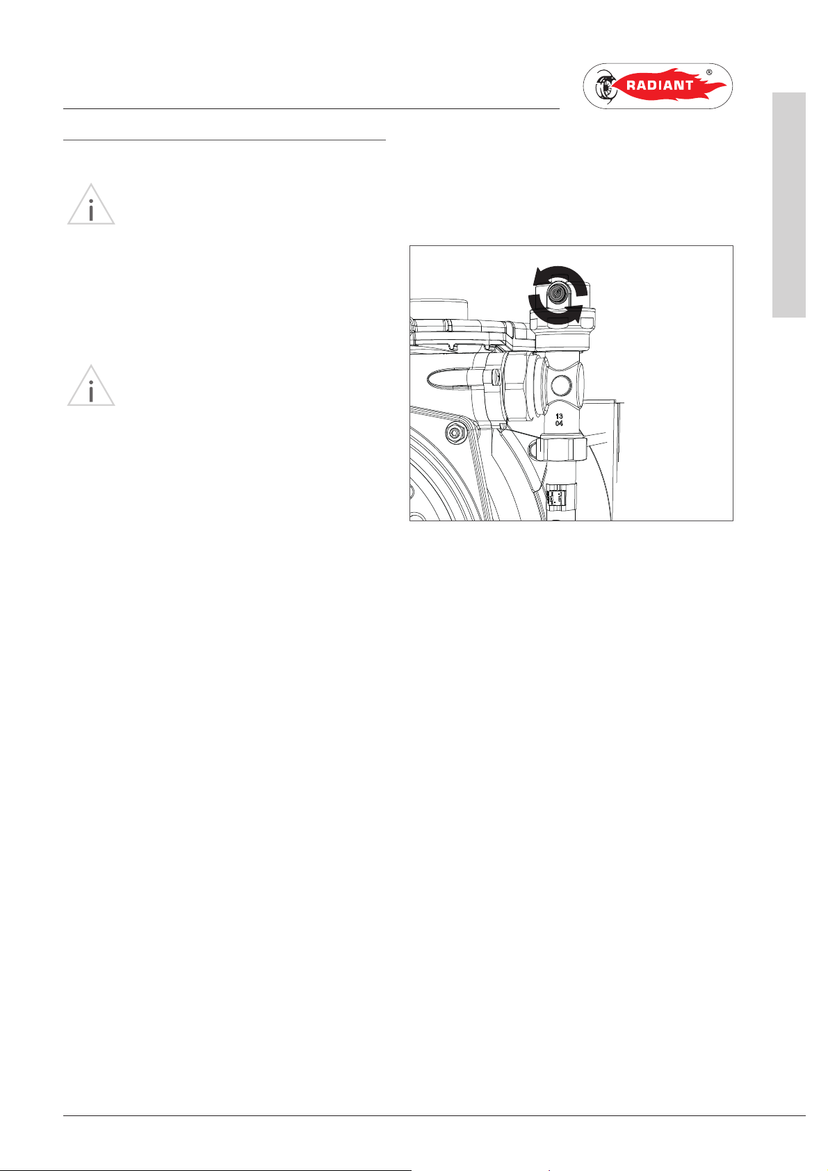
Before powering up the boiler, fill the system as
follows:
tap until the pressure gauge reaches the
design pressure.
fig. 1
1. slightly loosen the cap of the jolly valve placed
on the top of the condensing block to release
the air form the top of the system (fig.1);
2. check that the jolly valves vent the air present
in the system are not blocked
3. open the general domestic water input tap and
load the system by exhaling all the air;
4. use pressure gauge present in the system to
1 Riempimento dell'impianto_MIAH4_R1K 10 0_v.1_ EN
make sure that the system pressure reaches
the design value;
5. after performing this operation, make sure
that the loading tap is properly closed.
6. Open the air relief valves of the radiators and
check the air removal process. When the
water starts to leak close the radiators air
relief valves.
7. If after performing these operations you
observe a decrease of the water pressure
inside the system, open once again the loading
23
R1K 50 - RAD - ING - Manuale - 1801.1_SK.3
Page 24

INSTALLER
1.1.15. FILLING THE CONDENSATE
Before starting the boiler you have to fill the
condensate collection siphon in order to avoid fuel
reflux through the siphon.
Fill the condensate collection siphon as follows
(see fig. 1):
› With a glass pour the water in the heat
exchanger’s flue exhaust duct outlet (see fig. 1),
up to fill the condensate trap to the highest point
“T” (fig. 1);
› Connect the dedicated flexible condensate
draining tube to a waste disposal system.
The condensate can be drained directly in
the sewerage system by inserting an easily
serviceable siphon.
1. INSTALLATION
COLLECTION SIPHON
T
fig. 1
24
1 Riempimento del sifone condensa _recaplast_ R1K 50_EN
R1K 50 - RAD - ING - Manuale - 1801.1_SK.3
Page 25

1.1.16. ANTI-FREEZE PROTECTION
The boiler is protected against freezing thanks to
the electronic board preparation with functions
that start the burner and heat the concerned parts
when their temperature goes below the minimum
pre-set values, protecting the boiler up to an
external temperature of -10 °C.
The device starts when the hot water temperature
goes below 12°C, automatically starting the burner
until the heating flow water temperature reaches
the 30°C and, in presence of a return sensor, until
the heating return water temperature reaches the
20°C.
The system starts even if on the display appears
“OFF”, as long as the boiler is connected to the
power (230 V) and gas supply.
1. INSTALL ATION
DILUTION PERCENTAGE OF CLEANPASS
FLUIDO AG
ANTIFREEZE ETHYLENE GLYCOL
(%) VOLUME (°C)
20 -7.5
30 -13
35 -18
40 - 22.5
45 -28
50 -33.5
55 -42
60 -50
RECOMMENDED MINIMUM PERCENTAGE OF
GLYCOL : 20 %
TEMPERATURE
FREEZING POINT
INSTALLER
1 Protezione antigelo_firm.L181E_EN
For long periods of standby, please empty the
boiler and the plant.
If the temperature goes below -10° centigrades,
please fill the plant with anti-freeze liquid
(CLE ANPASS FLUIDO AG cod. 98716LA) and insert
and electrical resistances kit (cod. 82259LP).
R1K 50 - RAD - ING - Manuale - 1801.1_SK.3
25
Page 26

INSTALLER
1. INSTALLATION
1.1.17. GAS CONNECTION
DANGER
In order to connect the gas connector of
the boiler to the supply pipe use a stop seal of an
appropriate size and material. The use of hemp,
teflon tape or similar materials is strictly forbidden.
BEFORE PERFORMING THE GAS CONNECTION,
MAKE SURE THAT:
› the gas adduction line complies with the
standards and regulations in force;
› the tubing's section suits the requested capacity
and its length;
› the tubing is equipped with all safety and control
devices required by the standards in force;
› the internal and external seals of the gas infeed
plant are checked;
› the device is suitable for use with the type of
gas available by checking the boiler data plate
(placed on the inner side of the front casing. If
they do not match you must take the necessary
measures to adapt the boiler to another type of
gas (see chapter GAS TRANSFORMATION);
› the gas supply pressure falls within the values
indicated on the data plate.
1.1.18. ELECTRICAL CONNECTION
DANGER
The equipment is electrically safe only
if it is properly connected to an efficient grounding
system, performed in compliance with the safety
standards in force. You should check this essential
safety requirement. If in doubt, request an accurate
check of the electrical system performed by qualified
staff, as the manufacturer is not responsible for any
damages caused by lack of grounding system.
› Make sure that the electrical systems is
suitable for the maximum power absorbed by
the equipment, value indicated on the data plate.
› make sure that the cables section is appropriate
for the maximum power absorbed by the
equipment and that it is however not lower than
2
.
1 mm
› The equipment works with alternating current
of 230 V and 50 Hz. The electrical connection
must be performed using an all-pole switch with
an opening of at least 3 millimetres between
contacts placed upstream from the device.
WARNING
Make sure that the phase and neutral
cables connection is performed in compliance with
the wiring diagram (see chapter POWER SUPPLY).
WARNING
It is strictly forbidden the use of adaptors,
multiple plugs and/or extensions for the general
power supply of the equipment from the electrical
network.
1 Allacciamento gas_elettrico_MIAH4_EN
26
R1K 50 - RAD - ING - Manuale - 1801.1_SK.3
Page 27

1.1.19. POWER SUPPLY
1. INSTALL ATION
INSTALLER
To power the boiler connect the electrical cables
to the terminal inside the control panel as follows:
DANGER
Cut off the voltage from the main switch.
› remove the boiler's front casing (refer to chapter
ACCESSING THE BOILER).
› loosen the two screws and remove the plate “A”
(see fig. 1).
› after removing the plate, connect the electrical
cables to terminal “B” (see fig. 1):
· the yellow/green cable to the terminal marked
with grounding symbol “
· the blue cable to the terminal marked with
“N”.
”.
A
SeSe
TaTa
N
L
B
BLUE
YELLOW/GREEN
BROWN
fig. 1
1 Alimentazione elettrica_EN
· the brown cable to the terminal marked with
“L”.
After performing these operations, remount plate
“A” and the front casing.
R1K 50 - RAD - ING - Manuale - 1801.1_SK.3
27
Page 28

INSTALLER
1.1.20. OPTIONAL ELECTRICAL
The cables should be inserted inside the boiler
using the cable glands ‘P1’ and ‘P2’ placed under
the board (see fig. 1). Make a hole on the cable
gland, smaller than the cable diameter, to make
sure that the air cannot pass through.
To wire the optionals below:
• (SE) EXTERNAL TEMPERATURE PROBE CODE
73518LA
• (TA) ENVIRONMENT THERMOSTAT
CONNECTIONS
1. INSTALLATION
fig. 1
P1
P2
• (CR) REMOTE CONTROL OPEN THERM CODE
40-00017
use the terminal placed inside the control panel
as follows:
DANGER
Cut off the voltage from the main switch.
› remove the front casing of the boiler (see
chapter ACCESSING THE BOILER); unscrew the
screws and remove plate “A” (see fig. 2).
› After removing the plate, connect the electrical
cables to terminal “B” (see fig. 2):
· For the external temperature Probe connect
the two non-polarized conductors to the SeSe contacts.
· For the environment Thermostat or Remote
control, first remove the bridge on the TaTa contacts and then connect the two nonpolarized conductors to the Ta-Ta contacts.
After performing these operations, remount plate
“A” and the front casing.
SE
A
SeSe
TaTa
N
TA
L
CR
B
fig. 2
NOTA BENE: In case of simultaneous presence of external
probe and remote control, the modulation board only sends the
external temperature value to the remote device without using it
for modulation. The communication between board and remote
control takes place independently from the boiler's operating
mode and after establishing the connection, the display shows
the symbol ‘
’.
1 Collegamenti elettrici opzionali_ SE_TA_CR_MIA H4 - R1K 50_EN
28
R1K 50 - RAD - ING - Manuale - 1801.1_SK.3
Page 29

1. INSTALL ATION
INSTALLER
To wire the optionals below:
DANGER
Cut off the voltage from the main switch.
• (TP) DOMESTIC HOT WATER PRE-HEATING
DEACTIVATION TIMER
› remove the boiler's front casing (refer to chapter
ACCESSING THE BOILER).
• (CT) TELEPHONE DIALER
› remove the crankcase of the control panel
• BUS 0-10V
(see chapter ACCESSING THE ELECTRONIC
BOARD).
• (SVZ) CONTROL BOARD FOR AREA VALVES
CONNECTED TO A REMOTE CONTROL COD. 6500030
use the electronic board placed inside the control
panel as follows:
MIAH4
7
5
4
3
2
1
M10
M15
68
67
66
65
64
63
62
TP
CT
1 Collegamenti elettrici opzionali_MIAH4_no PM_EN
BUS+
GND
COD.40-00133
61
60
59
58
57
M16
M14
ar
56
ar
55
ne
54
ne
53
ma
52
ce
51
M13
4443424140
M12
3736353433
39
38
32
M9
98
6
M8
29
28
31
30
27
M7
M5
BUS 0-10V
› after removing the crankcase, connect the
items below to the electronic board (see fig. 1):
After performing these operations, remount the
crankcase and the front casing.
SVZ
11
10
26
fig. 1
M4
M3
12
13
14
15
16
17
M2
M1
1
gr
2
ar
3
4
SRB
5
N
6
M4
VZR
L
TAZ 2
VZ2 VZ1
TAZ 1
7
98
M2
ro
ne
L
220 V - 50 Hz
N
FC FC
SR: RETURN PROBE FC: AREA VALVES LIMIT SWITCH
SRB: REMOTE LED FOR SIGNALLING BOILER BLOCK GR: GREY
TAZ1: ENVIRONMENT THERMOSTAT AREA 1 AR: ORANGE
TAZ 2: ENVIRONMENT THERMOSTAT AREA 2 NE: BLACK
VZ1: AREA 1 VALVE MA: BROWN
VZ2: AREA 2 VALVE CE: LIGHT BLUE
VZR: REMOTE CONTROLLED AREA VALVE RO: RED
R1K 50 - RAD - ING - Manuale - 1801.1_SK.3
29
Page 30

INSTALLER
REMOTE BOILER SYSTEM - BOILER PROBE AND DIVERTER VALVE CONNECTION
- clamp M9 - boiler probe: insert the boiler probe cable inside the panel inserting the terminals 35 and
34. It is not necessary to follow an order of wires.
- clamp M4 - diverter valve: connect the motor cable of the diverter valve by means of the molex clamp.
Insert the cable inside the tool panel and connect the terminals of the cable to the clamp M4 paying
attention to the combinations: blue – clamp no. 9; brown – clamp no. 8; black – clamp no. 10.
1. INSTALLATION
brown
blue
black
7
5
4
3
2
1
M10
M15
68
67
66
65
64
63
62
61
60
59
58
57
M16
M14
56
55
54
53
52
51
M13
4443424140
M12
3736353433
39
32
38
M9
98
6
M8
31
M7
11
10
M4
12
13
14
15
16
17
M2
29
28
30
27
26
M5
RECIRCULATION
HOT WATER
COLD WATER
DOMESTIC CIRCUIT PROBE
REMOTE BOILER
black
black
max. 8 m
1 Collegamenti elettrici opzionali_VD+SB_MIAH4 _ R1K 50_ no INAIL_EN
fig. 1
30
R1K 50 - RAD - ING - Manuale - 1801.1_SK.3
Page 31

1. INSTALL ATION
INSTALLER
1.1.21. FUME EXHAUST FITTINGS
WARNING
In order to ensure proper operation and
efficiency of the device you have to connect the boiler
fume exhaust fitting to the fume exhaust duct using
appropriate polypropylene flue fittings for condensing
boilers. It is recommended to install discharge
systems approved by Radiant.
WARNING
You cannot use traditional flue fittings for
the discharge ducts of the condensing boilers, nor
vice versa.
WARNING
For fumes exhaust and condensate
collection, please follow the technical standards in
force.
› For all discharge ducts, with regard to the
fumes path, you should provide an uphill slope
(outwards) so as to favour the reflux of the
condensate towards the combustion chamber,
suitably realized to collect and drain acid
condensate.
› The discharge duct must be perpendicular with
the opposite internal wall of the chimney or of
the fumes exhaust duct (fig. 1).
fig. 1
1 Raccordi fumari_cond_EN
› For all air suction ducts, with regard to the air
path, you should provide an uphill slope (towards
the boiler) so as to avoid the protrusion inside
the duct of rain water, dust or foreign objects.
› In case of horizontal co-axial system installation,
correctly place the horizontal co-axial terminal
suitably realized to respect the slopes inside the
fumes duct and to protect the air suction duct
from adverse weather conditions.
› In order to discharge the fumes through a fumes
exhaust duct carefully follow the technical
standards in force.
› Make sure that the discharge tube doe not
protrude inside the fumes exhaust duct, stop
before it reaches the inner surface of the latter.
31
R1K 50 - RAD - ING - Manuale - 1801.1_SK.3
Page 32

INSTALLER
1.1.22. TYPES OF FUME EXHAUST
KIT AK 50 - HORIZONTAL CO-AXIAL SYSTEM
Ø80/125 INTERNAL POLYPROPYLENE DUCT
ADJUSTABLE AT 360°.
It allows fumes discharge and air intake from
external wall.
Suitable only for condensing boilers.
It allows fuel gas discharge and air intake for
combustion through co-axial ducts, the external
one for air intake, the plastic internal one for
fumes discharge.
1. INSTALLATION
SYSTEMS
PLEASE SEE THE MA XIMUM DISCHARGE LENGTH
IN THE TABLE IN CHAPTER “TECHNICAL DATA”.
The maximum discharge length (or linear
reference length) can be calculated summing the
length of the linear tube and that equivalent to
each additional curve with respect to the first.
Subsequent addition of a curve is similar to adding
a linear length of tube according to the indications
below:
co-axial curve Ø80/125 at 90° = 0.8 m
co-axial curve Ø80/125 at 45° = 0.5 m
Ø100
Ø80
Ø125
116,5
1 Tipologia di scarico_AK_50_EN
32
R1K 50 - RAD - ING - Manuale - 1801.1_SK.3
Page 33

KIT CK 50 - VERTICAL CO-AXIAL SYSTEM Ø80/125
INTERNAL POLYPROPYLENE DUCT.
It allows fumes discharge and air intake directly
from roof.
Suitable only for condensing boilers.
It allows fuel gas discharge and air intake for
combustion through co-axial ducts, the external
one for air intake, the plastic internal one for
fumes discharge.
PLEASE SEE THE MA XIMUM DISCHARGE LENGTH
IN THE TABLE IN CHAPTER “TECHNICAL DATA”.
The maximum discharge length (or linear
reference length) can be calculated summing the
length of the linear tube and that equivalent to
each additional curve with respect to the first.
1. INSTALL ATION
INSTALLER
1 Tipologia di scarico_CK_50_EN
Subsequent addition of a curve is similar to adding
a linear length of tube according to the indications
below:
curve Ø80/125 at 90° = 0.8 m
curve Ø80/125 at 45° = 0.5 m
Ø125
Ø 80
Ø 100
R1K 50 - RAD - ING - Manuale - 1801.1_SK.3
33
Page 34

INSTALLER
KIT EK 50 - SPLIT SYSTEM Ø80 MADE OF
POLYPROPYLENE
The two tubes system allows fumes discharge
through the fumes exhaust duct and air intake
from the environment.
Suitable only for condensing boilers.
It allows discharging fuel gas and air suctioning
for combustion through two separated ducts.
PLEASE SEE THE MAXIMUM DISCHARGE AND
INTAKE LENGTH IN THE TABLE IN CHAPTER
“TECHNICAL DATA”.
The maximum discharge and intake length
(or linear reference length) can be calculated
summing the length of the linear tube and that
equivalent to each additional curve with respect to
the first.
1. INSTALLATION
Subsequent addition of a curve is similar to adding
a linear length of tube according to the indications
below:
curve Ø80 at 90°= 3 m
curve Ø80 at 45°= 1.4 m
150
Ø80
204
Ø80
1 Tipologia di scarico_EK 50_EN
34
R1K 50 - RAD - ING - Manuale - 1801.1_SK.3
Page 35

KIT FK 50 - SPLIT SYSTEM Ø80 MADE OF
POLYPROPYLENE
The two tubes system allows fumes discharge
through the roof and air intake from the
environment.
Suitable only for condensing boilers.
It allows discharging fuel gas and air suctioning
for combustion through two separated ducts.
PLEASE SEE THE MAXIMUM DISCHARGE AND
INTAKE LENGTH IN THE TABLE IN CHAPTER
“TECHNICAL DATA”.
The maximum discharge and intake length
(or linear reference length) can be calculated
summing the length of the linear tube and that
equivalent to each additional curve with respect to
the first.
1. INSTALL ATION
INSTALLER
Subsequent addition of a curve is similar to adding
a linear length of tube according to the indications
below:
curve Ø80 at 90°= 3 m
curve Ø80 at 45°= 1.4 m
1 Tipologia di scarico_FK 50_EN
Ø80
1198
204
Ø80
R1K 50 - RAD - ING - Manuale - 1801.1_SK.3
35
Page 36

Page 37

1. SUPPORT CENTRE SECTION2. SUPPORT CENTER SECTION
All operations described below relative to first start-
up, maintenance and replacement should be performed
only by qualified personnel and authorized by RADIANT
BRUCIATORI S.p.A.
Page 38

2. FIRST START-UP
2.1. FIRST START-UP
2.1.1. PRELIMINARY OPERATIONS
The first start-up operations consist in checking
SUPPORT CENTRE
the correct installation, adjustment and operation
of the device. Proceed as follows:
› check the inner system sealing in accordance
with the indications provided by standard and
regulations in forced;
› check if the gas used is suitable for the boiler;
› check if the gas capacity and relative pressures
comply with those on the plate;
› check the intervention of the safety device in
case of lack of gas;
› make sure that the device supply voltage
corresponds with that on the plate (230 V – 50
Hz) and that the wiring is correct;
FOR FIRST START-UP
› make sure that there are no flammable liquids
or materials near the device;
› open the boiler gas tap and make sure that there
are no gas leaks upstream from the device (the
burner gas connection must be checked while
the machine is running);
› in case of new installation of the gas supply
network, the air inside the tubes may block the
device at its first start-up. You might have to
repeat the start-up procedure to purge all the
air inside the tube.
38
› make sure that the grounding system works
properly;
› make sure that the combustion air adduction
and fumes and condensate discharge take
place properly in compliance with the Local and
National Laws and Standards in force;
› make sure that the fumes discharge tube and
its connection to the fume exhaust duct comply
with the requirements of the Local and National
Laws and Standards;
› make sure that the heating system gate valves
are open;
› make sure that there is no intake of gaseous
products within the system;
R1K 50 - RAD - ING - Manuale - 1801.1_SK.3
2 Operazioni preliminari per l a prima acc_ EN
Page 39

2. FIRST START-UP
2.1.2. BOILER COMMISSIONING
WARNING
Make sure that the system is correctly
filled.
Proceed with boiler commissioning as follows:
Make sure the gas feed valve is switched off
› Power the boiler.
THE START-UP SYSTEM WILL AUTOMATICALLY
ACTIVATE THE SYSTEM AIR RELIEF CYCLE
FUNCTION DISPLAYED ON SCREEN WITH CODE
“F33” (ONLY AT FIRST START-UP WILL LAST FOR
5 MINUTES*). When function “F33” is active, the
pump is enabled and the burner start-up request
is disabled. The boiler can work normally only
after completing the operation.
tube. Before repeating the operation, wait at
least 5 seconds from the last start-up attempt
and unlock the boiler from “E01” error code by
pressing the Reset ‘
(*)
The boiler performs the system venting cycle function
(5 minutes) only during the first starting. After every water
pressure reset the boiler will automatically perform a
reduced system venting cycle (2 minutes). During this
function the display shows F33 code. The correct boiler
operation will be allowed only after this operation has
been completed.
’ key.
SUPPORT CENTRE
› Make sure the circulating pump is unblocked.
› If it should be blocked, wait for the circulating
pump to activate the automatic reset (lasting 3
min.)
› If the circulating pump should be still blocked,
activate the circulating pump automatic reset
again (further 3 minutes), and switch off the
power supply and switch it on again.
2 Messa in funzione della caldaia_MIAH4_PM_EN
› Open the gas tap.
› Use the button ‘
operation mode. If the symbol is displayed fixed,
it means that the function has been activated.
› The burner will start as soon as the thermostat
contact is closed ;
› If the flame is missing, the board will repeat the
start-up operations after post-ventilation (20
seconds).
’ to select the desired
› You might have to repeat the start-up operation
several times to release all the air inside the gas
39
R1K 50 - RAD - ING - Manuale - 1801.1_SK.3
Page 40

2. FIRST START-UP
2.1.3. CO2 VALUE CHECK AND
the casing assembled, while the gas valve should be
adjusted with the casing open.
SUPPORT CENTRE
To check and calibrate the CO2 value to minimum
and maximum heating power proceed as follows
for every single unit:
FOR MINIMUM HEATING POWER
› Activate the chimney sweep function (F07) by
holding for 7 seconds the key ‘
time of the function is 15 minutes).
› Insert the fumes analyser probe in the suitable
‘PF’ fumes inlet (fig. 1), then make sure that
the CO
in “Technical data”, otherwise unscrew the
protection screw ‘A’ (fig. 2) and adjust using a
4 Allen wrench the screw ‘2’ (fig. 2) of the OffSet adjuster. To increase the CO
screw clockwise and vice-versa if you want to
decrease it. Once completed the adjustment,
tighten the protection screw ‘A’ (fig. 2) on the
Off-Set adjuster.
CALIBRATION
WARNING
The CO
value complies with the indications
2
value should be checked with
2
’ (the maximum
value, turn the
2
› Then press the key ‘
make sure that the CO
’ of the heating and
value did not change
2
to minimum, if changed repeat the calibration
described in the previous paragraph.
› Deactivate the chimney sweep function by
switching the boiler to the ‘OFF’ operating mode
using the button ‘
’.
fig. 1
PF
40
FOR MAXIMUM HEATING POWER
› Press the key ‘
’ of the heating in order to
calibrate the maximum heating power.
› Make sure that the CO
value complies with the
2
requirements indicated in chapter “Technical
data”, otherwise adjust using screw ‘1’ (fig. 2) of
the gas flow adjuster. To increase the CO
value,
2
turn the screw anti-clockwise and vice-versa if
you want to decrease it.
› After each adjustment variation on screw ‘1’
(fig. 2) of the gas flow adjuster you have to wait
for the boiler to stabilize itself to the set value
(about 30 seconds).
R1K 50 - RAD - ING - Manuale - 1801.1_SK.3
fig. 2
+
2 Ve r i fi c a e taratura del valore di CO2_MIA H4_ R1K 50_firm.L181E_ EN
+
1
2
A
Page 41

2. FIRST START-UP
2.1.3. ACCESSING AND PROGRAMMING THE PARAMETERS
To access the parameters menu and adjust their values, follow the procedure below:
SUPPORT CENTRE
1. Press the button ‘
mode displayed using the symbol ‘
2. Hold at the same time the keys ‘
’ until on the display appears the symbol ‘
’with the message ‘P00’, and release the keys
’ and ‘ ’.
‘
’ to select the OFF
’.
’ and ‘
2 Access o e programmazione dei parametri_solo risc_MIAH4 _R2_G_EN
3. Use the keys ‘
circuit
to select the parameter to be edited.
’ and ‘ ’ of the heating
41
R1K 50 - RAD - ING - Manuale - 1801.1_SK.3
Page 42

4. Use the keys ‘ ’ and ‘ ’ of the symbol ‘S’
SUPPORT CENTRE
2. FIRST START-UP
to change the value of the parameter.
5. Press the key ‘
and wait for the display to stop blinking,
indication of the fact that the adjustment was
implemented.
6. To exit the parameters menu, hold at the same
time the keys ‘
symbol ‘
’ to appear on the display.
’ to confirm the action
’ and ‘ ’ and wait for the
2 Access o e programmazione dei parametri_solo risc_MIAH4 _R2_G_EN
42
R1K 50 - RAD - ING - Manuale - 1801.1_SK.3
Page 43

2. FIRST START-UP
2.1.4. DIGITECH CS PARAMETERS TABLE
PARAMETER DESCRIPTION RANGE FUNCTION
P00 BOILER MODEL SELECTION 0 - 10 0 = 13 K W
1 = 18 KW (HEAT.) / 24 KW
(DOMESTIC)
2 = 25 KW
3 = 28 KW
4 = 34 KW
5 = 55 KW
SUPPORT CENTRE
6 = 100 KW
7 = R1K 18_24-R2K
24-R2KA 24 (IN ALL
VERSIONS)
8 = R1K 25_28-R2K
28-R2KA 28 (IN ALL
VERSIONS)
9 = R1K 34-R2K 34-R2K A
34 (IN ALL VERSIONS)
10 = R1K 50
2 Tabell a par ametri _MI AH4 _ firm.L 224 A _ EN
P01 BOILER TYPE SELECTION 0 - 5 0 = ISTANTANEOUS R2K
1 = ISTANTANEOUS RKR
2 = ACCUMULATION
3 = ACCUMULATION
COMFORT
4 = ISTANTANEOUS
COMFORT - FAST H2O
5 = HEATING ONLY
R1K 50 - RAD - ING - Manuale - 1801.1_SK.3
43
Page 44

2. FIRST START-UP
PARAMETER DESCRIPTION RANGE FUNCTION
P02 GAS TYPE SELECTION
SUPPORT CENTRE
P03 SETTING THE HEATING TEMPERATURE
P04 HEATING RUN-UP
ATTENTION:
READ THE INSTRUCTION IN CHAPTER ‘GAS TRANSFORMATION’ BEFORE
CHANGING THIS PARAMETER.
IN CASE THE BOILER IS INSTALLED A S PART OF A LOW TEMPERATURE
CIRCUIT, PLEASE INSTALL A SAFET Y THERMOSTAT ON THE HEATING
FLOW, WHICH CAN STOP THE BOILER ACTIVITY IN CASE OF HIGH
HEATING FLOW TEMPERATURE. THE COMPANY ASSUMES NO LIABILITY
FOR DAMAGE CAUSED TO PERSONS OR FOR FAILURE TO COMPLY WITH
THESE INSTRUCTIONS.
THROUGH THIS PARAMETER YOU CAN SET THE TIME, DURING START-
UP PHA SE, NECESSARY FOR THE BOILER TO REACH THE MAXIMUM SET
POWER (ON THE HEATING SIDE).
0 - 1 0 = METHANE
1 = LPG
0 - 1 0 = STANDA RD (30-80 °C)
(SET BY DEFAULT)
1 = REDUCED (25-45 °C)
FOR FLOOR SYSTEMS
0 - 4 0 = (DISABLED)
1 = 50 SECONDS
(SET BY DEFAULT)
2 = 100 SECONDS
3 = 200 SECONDS
P05 ANTI-WATER HAMMER SELECTION
ONCE THIS FUNCTION IS ENABLED, THE DHW CONTACT WILL BE
DELAYED FOR A TIME EQUAL TO THE SET VALUE.
P06 DOMESTIC CIRCUIT PRESERVATION FUNCTION
(ONLY FOR ISTANTANEOUS BOILERS)
THROUGH THIS PARAMETER YOU CAN PRESERVE THE CIRCULATOR THE
DIVERTER VALVE IN DOMESTIC POSITION FOR A PERIOD OF TIME EQUAL
TO THE POST-CIRCULATION (SEE PAR AME TER P09), SO AS TO MAINTAIN
THE SECONDARY EXCHANGER HOT.
P07 HEATING TIMING
THROUGH THIS PARAMETER YOU CAN SET THE MINIMUM TIME FOR
WHICH THE BURNER WILL BE TURNED OFF ONCE THE HE ATING
TEMPERATURE REACHED THE USER SET TEMPERATURE.
4 = 400 SECONDS
0 - 20 0 = DISABLED
1 - 20 = THE VALUE IS
EXPRESSED IN SECONDS
0 - 1 0 = DISABLED
(SET BY DEFAULT)
1 = ENABLED
0 - 90 VALUE EXPRESSED
IN MULTIPLES OF 5
SECONDS
(PRE-SET AT 36 X 5 = 180
SECONDS)
2 Tabell a par ametri _MI AH4 _ firm.L 224 A _ EN
44
R1K 50 - RAD - ING - Manuale - 1801.1_SK.3
Page 45

2. FIRST START-UP
PARAMETER DESCRIPTION RANGE FUNCTION
P08 POST-CIRCULATION HEATING TIMING
THROUGH THIS PARAMETER, IT IS POSSIBLE TO SET THE OPERATION
TIME OF THE PUMP AFTER THE M AIN BURNER TURNS OFF DUE TO THE
ENVIRONMENT THERMOSTAT.
P09 POST-CIRCULATION DOMESTIC / STORAGE TIMING
THROUGH THIS PARAMETER, IT IS POSSIBLE TO SET THE OPERATION
TIME OF THE PUMP
TEMPERATURE SET IN THE BOILER.
P10 DOMESTIC FAN MINIMUM SPEED ADJUSTMENT
THROUGH THIS PARAMETER YOU CAN SET THE FAN MINIMUM SPEED
IN DOMESTIC PHASE, THAT CORRESPONDS TO THE MINIMUM BURNER
POWER DURING A REQUEST TO OPERATE IN DOMESTIC MODE.
THE VALUE IS PRE-SET BASED ON THE SE T POWER (SEE PARAME TER
P00) AND ON THE GAS TYPE (SEE PARAMETER P02)
AFTER CLOSING THE TAP OR RE ACHING THE
0 - 90 VALUE EXPRESSED
IN MULTIPLES OF 5
SECONDS
(PRE-SET AT 36 X 5 = 180
SECONDS)
0 - 90 VALUE EXPRESSED
IN MULTIPLES OF 5
SECONDS
(PRE-SET AT 24 X 5 = 120
SECONDS)
45 - VALUE
SET FOR
PARAMETER
P11
THE VALUE IS
EXPRESSED IN HERTZ
(1HZ = 30 RPM)
SUPPORT CENTRE
P11 DOMESTIC FAN MAXIMUM SPEED ADJUSTMENT
THROUGH THIS PARAMETER YOU CAN SET THE FAN MA XIMUM SPEED
IN DOMESTIC PHASE, THAT CORRESPONDS TO THE MAXIMUM BURNER
POWER DURING A REQUEST TO OPERATE IN DOMESTIC MODE.
THE VALUE IS PRE-SET BASED ON THE SE T POWER (SEE PARAME TER
P00) AND ON THE GAS TYPE (SEE PARAMETER P02)
VALUE
SET FOR
PARAMETER
P10 - 203
THE VALUE IS
EXPRESSED IN HERTZ
(1HZ = 30 RPM)
2 Tabell a par ametri _MI AH4 _ firm.L 224 A _ EN
P12 HEATING FAN MINIMUM SPEED ADJUSTMENT
THROUGH THIS PARAMETER YOU CAN SET THE FAN MINIMUM SPEED
IN HEATING PHASE, THAT CORRESPONDS TO THE MINIMUM BURNER
POWER DURING A REQUEST TO OPERATE IN HEATING MODE. [SEE
CHAPTER ‘HEAT CAPACITY DIAGR AM (K W) – ELECTRIC FAN FREQUENCY
(HZ)’].
THE VALUE IS PRE-SET BASED ON THE SE T POWER (SEE PARAME TER
P00) AND ON THE GAS TYPE (SEE PARAMETER P02)
45 - VALUE
SET FOR
PARAMETER
P13
THE VALUE IS
EXPRESSED IN HERTZ
(1HZ = 30 RPM)
R1K 50 - RAD - ING - Manuale - 1801.1_SK.3
45
Page 46

2. FIRST START-UP
PARAMETER DESCRIPTION RANGE FUNCTION
P13 HEATING FAN MAXIMUM SPEED ADJUSTMENT
SUPPORT CENTRE
P14 STARTING STEP ADJUSTMENT
P15 ANTI-LEGIONELLA FUNCTION
THROUGH THIS PARAMETER YOU CAN SET THE FAN MA XIMUM SPEED
IN HEATING PHASE, THAT CORRESPONDS TO THE MAXIMUM BURNER
POWER DURING A REQUEST TO OPERATE IN HEATING MODE [SEE
CHAPTER ‘HEAT CAPACITY DIAGR AM (K W) –ELECTRIC FAN FREQUENCY
(HZ)’].
THE VALUE IS PRE-SET BASED ON THE SE T POWER (SEE PARAME TER
P00) AND ON THE GAS TYPE (SEE PARAMETER P02)
THROUGH THIS PARAMETER YOU CAN SET THE FAN SPEED DURING
START-UP
THE VALUE IS PRE-SET BASED ON THE SE T POWER (SEE PARAME TER
P00) AND ON THE GAS TYPE (SEE PARAMETER P02)
(FOR STORAGE BOILERS ONLY)
THROUGH THIS PARAMETER YOU CAN ACTIVATE/DEACTIVATE THE
“ANTILEGIONELLA” HEAT TRE ATMENT OF THE STORAGE TANK. EVERY
7 DAYS THE WATER TEMPERATURE INSIDE THE STOR AGE IS HEATED
BEYOND 60 °C THUS GENERATING A BURNING HAZARD. KEEP UNDER
CONT ROL SUCH DO MESTICH H OT WATER TRE ATMENT (A ND INFORM TH E
USERS) TO AVOID UNFORSEEA BLE DAMAGES TO PERSONS, ANIMALS
AND PROPERTY. A THERMOSTATIC VALVE SHOULD BE INSTALLED AT
THE DOMESTIC HOT WATER OUTLET TO AVOID ANY BURNS.
VALUE
SET FOR
PARAMETER
P12 - 203
VALUE
SET FOR
PARAMETER
P10 - 203
0 - 1 0 = DISABLED
THE VALUE IS
EXPRESSED IN HERTZ
(1HZ = 30 RPM)
THE VALUE IS
EXPRESSED IN HERTZ
(1HZ = 30 RPM)
1 = ENABLED (PRE-
SET BY DEFAULT ON
STORAGE BOILERS ONLY)
46
2 Tabell a par ametri _MI AH4 _ firm.L 224 A _ EN
R1K 50 - RAD - ING - Manuale - 1801.1_SK.3
Page 47

2. FIRST START-UP
PARAMETER DESCRIPTION RANGE FUNCTION
P16 CLIMATE COMPENSATION CURVE
(ONLY WITH EXTERNAL PROBE CONNECTED)
YOU CA N CONNECT A N EX TERNA L TEMPER ATURE PR OBE (SEE CH APTER
‘ELECTRICAL CONNECTIONS’) THAT AUTOMATICALLY CHANGES THE
DELIVERY TEMPERATURE BA SED ON THE EXTERNAL MEA SURED
TEMPERATURE. THE NATURE OF THE CORRECTION DEPENDS ON THE
THERMO-ADJUSTMENT VALUE KD SET (SEE CHART).
THE SELECTION OF THE CURVE IS DETERMINED BY THE MAXIMUM
DELIVERY TEMPERATURE TM AND THE MINIMUM EXTERNAL
TEMPERATURE TE TAKING INTO ACCOUNT THE HOUSE INSUL ATION
DEGREE.
THE VALUES OF THE DELIVERY TEMPERATURES TM, REFER TO
STANDARD SYSTEMS 30-80 °C OR FLOOR SYSTEMS 25-4 5 °C. THE
SYSTEM T YPE CAN BE SET FROM PARAMETER P03.
Tm (°C)
45 MAX
80
75
70
65
35
60
55
50
30
45
40
35
Kd = 0
30
25
MIN
Kd = 15
Kd = 10
Kd = 5
Kd = 20
Kd = 25
Kd = 30
0 - 30 (SET BY DEFAULT AT
THE NUMBERING OF THE
VALUE CORRESPONDS
TO ‘KD’ CURVES ON THE
CHART (SEE CHART
BELOW).
25)
SUPPORT CENTRE
-10
-15-20
-5
P17 DISABLEMENT OF DOMESTIC HOT WATER LINE BY MEANS OF SWITCH (ONLY
2 Tabell a par ametri _MI AH4 _ firm.L 224 A _ EN
FOR FAST BOILERS)
5
0
Te (°C)
353025201510
0 - 1 0 = DISABLED
(SET BY DEFAULT)
BY ENABLING THIS PARAMETER IN THE PRESENCE OF A CONNECTION
(FOR EXAMPLE A BOILER CLOCK OR A TEMPERATURE THERMOSTAT) ON
1 = ENABLED
BOILER CLOCK SWITCH ON THE BOARD, THE REQUEST FOR BURNER
IGNITION ON THE D OMES TIC HOT WATER L INE WILL BE DISA BLED UPON
BOILER CLOCK SWITCH CLOSURE.
EXAMPLE 1: WITH THE BOILER CLOCK SWITCH OPEN, UPON THE
REQUEST FOR DOMESTIC HOT WATER, THE FLOW SWITCH AND THE
BOILER WILL TURN ON.
EXAMPLE 2: WITH THE BOILER CLOCK SWITCH CLOSE, UPON THE
REQUEST FOR DOMESTIC HOT WATER, THE FLOW SWITCH AND THE
BOILER WILL NOT TURN ON.
47
R1K 50 - RAD - ING - Manuale - 1801.1_SK.3
Page 48

2. FIRST START-UP
PARAMETER DESCRIPTION RANGE FUNCTION
P18 ENABLING BUS INDUSTRIAL PILOTING 0 -10V
SUPPORT CENTRE
P19 MINIMUM HEATING SETPOINT
P20 MAXIMUM HEATING SETPOINT
P21 MAXIMUM DOMESTIC SETPOINT
THROUGH THIS PARAMETER YOU CAN ENABLE OR DISABLE THE BUS
INDUSTRIAL INPUT 0-10 V TO SET THROUGH EX TERNAL BUS THE
BURNER POWER OR THE DELIVERY TEMPERATURE.
THROUGH THIS PARAMETER YOU CAN SET THE USER-ADJUSTABLE
MINIMUM HEATING TEMPER ATURE.
THROUGH THIS PARAMETER YOU CAN SET THE USER-ADJUSTABLE
MA XIMUM HEATING TEMPERATURE.
THROUGH THIS PARAMETER YOU CAN SET THE USER-ADJUSTABLE
MAXIMUM DOMESTIC TEMPERATURE.
0 - 2 0 = DISABLED
(SET BY DEFAULT)
1 = TEMPERATURE
CONTROL MODE
2 = POWER CONTROL
MODE
20 - 40 THE VALUE IS
EXPRESSED IN °C
40 - 90 THE VALUE IS
EXPRESSED IN °C
45 - 75 THE VALUE IS
EXPRESSED IN °C
P22 SET POINT 'T DELIVERY-RETURN
(ONLY WITH MODULATING PUMP AND RETURN PROBE CONNECTED)
THROUGH THIS PARAMETER YOU CAN SET THE TEMPERATURE
DIFFERENCE BET WEEN DELIVERY AND RETURN.
P23 MODULATING PUMP MINIMUM SPEED
(ONLY WITH MODULATING PUMP AND RETURN PROBE CONNECTED)
THROUGH THIS PARAMETER YOU CAN SET THE MINIMUM SPEED
VALUE OF THE MODULATING PUMP DURING A REQUEST TO OPERATE IN
HEATING MODE.
P24 MODULATING PUMP MAXIMUM SPEED
(ONLY WITH MODULATING PUMP AND RETURN PROBE CONNECTED)
THROUGH THIS PARAMETER YOU CAN SET THE MAXIMUM SPEED
VALUE OF THE MODULATING PUMP DURING A REQUEST TO OPERATE IN
HEATING MODE.
P25 D.H.W STORAGE TANK TEMPERATURE SETPOINT
(FOR STORAGE BOILERS ONLY)
THROUGH THIS PARAMETER YOU CAN SET THE PRIORITY STARTING
VALUE OF THE STORAGE TANK, COMPARED TO THE USER ADJUSTABLE
D.H.W SETPOINT.
0 0 = DISABLED
10 - 40 THE VALUE IS
EXPRESSED IN °C
50 - 70 THE VALUE IS
EXPRESSED IN
PERCENTAGE
2 Tabell a par ametri _MI AH4 _ firm.L 224 A _ EN
70 - 100 THE VALUE IS
EXPRESSED IN
PERCENTAGE
3 - 9 THE VALUE IS
EXPRESSED IN °C (PRE-
SET AT 9°C)
48
R1K 50 - RAD - ING - Manuale - 1801.1_SK.3
Page 49

2. FIRST START-UP
PARAMETER DESCRIPTION RANGE FUNCTION
P26
P27 MODBUS COMMUNICATION BAUD RATE
P28 MODBUS MODE 0 - 2 0 = ENABLED
MODBUS ADDRESS
BY MEANS OF THIS PARAMETER, IT IS POSSIBLE TO SET THE ADDRESS
OF THE B OARD ON MODB US IN ORDER TO P ERFORM A CA SCADE S YSTEM .
BY MEANS OF THIS PARAMETER, IT IS POSSIBLE TO SELECT THE
MODBUS COMMUNICATION BAUD RATE SUPPORTED BY THE SAME
INTERFACE.
1 - 16 BOILER NUMBERING FOR
MODBUS
0 - 5 0 = 9600
1 = 1200
2 = 2400
3 = 4800
4 = 9600
5 = 19200
1 = ENABLED WITH
LOCAL SETTINGS
SUPPORT CENTRE
2 = DISA BLED (SET BY
DEFAULT)
P29 ǻT HEATING POSTCIRCULATION
THROUGH THIS PARAMETER, IT IS POSSIBLE TO SET THE TEMPERATURE
DIFFERENCE FROM THE MAIN BURNER SHUTOFF, FOR THE
INTERVENTION OF THE ROOM THERMOSTAT, TO THE DISABLING OF THE
2 Tabell a par ametri _MI AH4 _ firm.L 224 A _ EN
P30 ǻ7 D.H.W./TANK POSTCIRCULATION
P31 HEATING MODE ANTI-FREEZE TEMPERATURE SETTING
PUMP IN HEATING MODE.
THROUGH THIS PARAMETER, IT IS POSSIBLE TO SET THE TEMPERATURE
DIFFERENCE FROM THE CLOSING OF THE TAP OR THE RE ACHING OF THE
TEMPERATURE SET IN THE BOILER TO THE DISABLING OF THE PUMP IN
HEATING MODE.
THROUGH THIS PARAMETER, IT IS POSSIBLE TO SET THE HEATING
WATER TEMPER ATURE AT WHICH THE ANTI-FREEZE PROTECTION
DEVICE STARTS WORKING.
0 - 25 THE VALUE IS
EXPRESSED IN °C (SET
BY DEFAULT AT 10 °C)
0 - 25 THE VALUE IS
EXPRESSED IN °C (SET
BY DEFAULT AT 10 °C)
5 - 12 THE VALUE IS
EXPRESSED IN °C (SET
BY DEFAULT AT 8 °C)
R1K 50 - RAD - ING - Manuale - 1801.1_SK.3
49
Page 50

2.1.6. ELECTRIC FAN FREQUENCY/HEAT CAPACITY DIAGRAM
SUPPORT CENTRE
2. FIRST START-UP
55
50
45
40
35
30
25
20
15
10
HEAT CAPACITY (kW)
5
0
35 50 65 80 95 110 125 140 155 170 185 200 215 230 245
G30
G20
G31
FREQUENCY (Hz)
GAS TYPE
MINIMUM FREQUENCY DURING
HEATING
MAXIMUM FREQUENCY DURING
G20 Hz 53 247
G30 Hz 53 225
G31 Hz 53 240
HEATING
2 Diagramma portata termica - frequenz a elettr_R1K 50_SK.3_EN
50
R1K 50 - RAD - ING - Manuale - 1801.1_SK.3
Page 51

2.2. MAINTENANCE
2. MAINTENANCE
2.2.5. GENERAL MAINTENANCE
WARNINGS
DANGER
Before each components cleaning or
replacement operation, ALWAYS cut off the POWER,
WATER and GAS supply of the boiler.
WARNING
To ensure greater life span and proper
operation of the device, during the maintenance
operations use only original spare parts.
ATTENTION
To ensure the efficiency and safety of the
device, the maintenance operations must be realized
on an annual basis. The operations described below,
are essential to the validity of the standard RADIANT
warranty and must be performed by professionally
qualified personnel in accordance with current
legislation and authorized by RADIANT.
Please perform the following operations once a year:
› check the integrity and the position of the sealed
chamber sealing gasket;
› check the primary exchanger, if necessary, clean
it;
› check the operation of the gas light up and safety
systems. If necessary, remove and clean the
flame detection and light up electrodes from
incrustations paying attention to respect the
distances with respect to the burner;
› check the heating circuit safety systems: limit
temperature safety thermostat; limit pressure
safety;
› check the pre-load pressure of the expansion
vessel;
› make sure that the permanent ventilation outlets
are present, correctly sized and functioning, based
on the installed devices. Respect the requirements
provided by Local and National legislation;
SUPPORT CENTRE
› Check that the system’s water PH is between 6.5
and 8.5;
› check the sealing of the gas components, and
2 Av ve rt enz e generali per la manutenzione_s olo risc_cond_EN
replace if necessary the gaskets;
› check the sealing of the water components, and
replace if necessary the gaskets;
› visually check the flame and the condition of the
combustion chamber;
› if necessary make sure that the combustion
is suitably adjusted and if required proceed as
indicated in section “CO2 VALUE CHECK AND
CALIBRATION”;
› remove and clean the burner from oxidation;
› periodically check the integrity of the fume
exhaustion system for safety and proper operation;
› check that the wiring is performed in compliance
with the requirements in the boiler instruction
manual;
› check the wiring inside the control panel;
› check the proper operation of the condensate
draining system, including the devices outside
the boiler such as condensate collection devices
installed along the path of the fume exhaust duct
or neutralization devices for acid condensate.
› check that the liquid flow is not obstructed and that
there are no combustion gas refluxes inside the
internal system.
51
R1K 50 - RAD - ING - Manuale - 1801.1_SK.3
Page 52

2.2.8. TECHNICAL DATA
Model R1K 50
CE certification no. 0476CQ0134
Discharge type type B2 3p-B 33 -C13 -C 33-
SUPPORT CENTRE
52
Energy efficiency 92/42 CEE no. stars 4
Energy efficiency EN13203-1 no. stars Maximum nominal heat capacity in heating circuit kW 50
Minimum nominal heat capacity in heating circuit kW 5
Useful thermal power - 60/80°C kW 49,19
Minimum useful thermal power - 60/80°C kW 4,83
Useful thermal power - 30/50°C kW 53,40
Performance at 100% Pn - 60/80°C % 98,37
Performance at 30% Pn - return 47°C % 102,8
Performance at 30% Pn - return 30°C % 108,83
Performance at 100% Pn - 30/50°C % 106,8
Maximum combustion Performance % 97,9
Fumes temperature at nominal heat capacity °C 66,4
Fumes temperature at minimum heat capacity °C 56,8
CO2 at nominal heat capacity - G20 % 9,3 - 9,1
CO2 at minimum heat capacity - G20 % 9,0 - 8,8
CO2 at nominal heat capacity - G30 % 11,3 - 11,1
CO2 at minimum heat capacity - G30 % 10,9 - 10,7
CO2 at nominal heat capacity - G31 % 10,3 - 10,1
CO2 at minimum heat capacity - G31 % 9,9 - 9,7
CO at nominal heat capacity ppm 68
Fumes mass at nominal heat capacity g/s 22,19
Fumes mass at minimum heat capacity g/s 2,28
NOx class class 6
Weighted Nox (0% O2) mg/kWh mg/kWh 51
Heating circuit
Adjustable heating temperature °C 30-80 / 25-45
Maximum operating temperature for heating circuit °C 80
Maximum operating pressure for heating circuit bar 3
Minimum operating pressure for heating circuit bar 0,3
Dimensional characteristics
Width mm 410
Depth mm 485
Height mm 640
Gross weight Kg 50
Water connections
Flow Ø 1 1/4”
Cold water Ø 1/2”
Gas Ø 3/4”
R1K 50 - RAD - ING - Manuale - 1801.1_SK.3
2. MAINTENANCE
C43-C53-C63-C83-C93
2 Dati tecnici_R1K 50_SK.3_EN
Page 53

2 Dati tecnici_R1K 50_SK.3_EN
2. MAINTENANCE
Return Ø 1 1/4”
Fume exhaust fittings
Maximum electric fan pressure available Pa 100
Minimum electric fan pressure available Pa 30
Max discharge length Ø60/100 - Hor Co-ax m 3
Max discharge length Ø80/125 - Hor Co-ax m 10
Max discharge length Ø60/60 - Hor Split m 6
Max discharge length Ø80/80 - Hor Split m 40
Max discharge length Ø60 - Hor duct m 5
Max discharge length Ø80 - Hor duct m 25
Max discharge length Ø60/100 - Vert Co-ax m 3
Max discharge length Ø80/125 - Vert Co-ax m 10
Max discharge length Ø60/60 - Vert Split m 6
Max discharge length Ø80/80 - Vert Split m 40
Max discharge length Ø60 - Vert duct m 5
Max discharge length Ø80 - Vert duct m 25
Electrical specifications
Voltage-frequency V/Hz 230/50
Max Absorbed Power W 108
Insulation rate IP X5D
Gas supply
Nominal supply pressure - G20 mbar 20
Heating Max. fan speed - G20 Hz 247
Heating Min. fan speed - G20 Hz 53
3
Fuel consumption - G20 m
Nominal Supply pressure - G30 mbar 30
Heating Max. fan speed - G30 Hz 225
Heating Min. fan speed - G30 Hz 53
Fuel consumption - G30 kg/h 3,94
Nominal Supply pressure - G31 mbar 37
Heating Max. fan speed - G31 Hz 240
Heating Min. fan speed - G31 Hz 53
Fuel consumption - G31 kg/h 3,88
/h 5,29
SUPPORT CENTRE
R1K 50 - RAD - ING - Manuale - 1801.1_SK.3
53
Page 54

2. MAINTENANCE
2.2.9. TECHNICAL ASSEMBLY
SUPPORT CENTRE
5
10
1
2
3
4
6
7
8
9
11
12
13
14
15
16
17
18
KEY
1. FUMES SAFETY THERMOFUSE
2. HEAT EXCHANGER
3. BURNER UNIT
4. DETECTION ELECTRODE
5. AIR SUCTION TUBE
6. PROPORTIONAL VENTURI
7. CIRCUL ATOR
8. CONDENSATE COLLECTION SIPHON
9. GAS VALVE
10. SYSTEM DRAINING TAP
11. AUTOMATIC AIR RELIEF VALVE
12. HEATING PROBE
13. SAFETY THERMOSTAT
14. LIGHT UP ELECTRODE
15. START-UP TRANSFORMER
16. ELECTRIC FAN
17. SAFETY VALVE 3 bar
18. WATER PRESSURE SWITCH
2 Complessivo tecnico_R1K 50_SK.2_EN
54
R1K 50 - RAD - ING - Manuale - 1801.1_SK.3
Page 55

2.2.6. HYDRAULIC BOARD
2. MAINTENANCE
1
2
6
10
11
3
12
4
5
13
14
SUPPORT CENTRE
6
7
8
9
sc
R
G
A
15
KEY
R. HEATING RETURN
G. GAS INLET
SC. CONDENSATE DRAIN
A. HEATING FORWARD
1. FUMES SAFETY THERMOFUSE
2. HEAT EXCHANGER
2 Schema idraulico_R1K 50_EN
3. BURNER UNIT
4. ELECTRIC FAN
5. GAS VALVE
6. AIR RELIEF VALVE
7. CIRCUL ATOR
8. SAFETY VALVE 3 bar
9. SYSTEM DRAINING TAP
10. HEATING PROBE
11. S A FE T Y THE R M O STAT
12. AIR SUCTION TUBE
13. PROPORTIONAL VENTURI
14. CONDENSATE COLLECTION SIPHON
15. WATER PRESSURE SWITCH
R1K 50 - RAD - ING - Manuale - 1801.1_SK.3
55
Page 56

2. MAINTENANCE
2.2.7. WIRING DIAGRAM
MP
SeSe
SUPPORT CENTRE
PM
ma
ce
TaTa
N
220 V
50 Hz
L
ER
ma
ce
ma
ce
5
7
6
4
M8
3
2
1
M10
98
11
10
M4
EA
Tra
M15
68
ma
67
ce
66
65
64
63
62
ma
61
gi
60
bi
59
58
gr
57
M16
M14
56
55
54
53
52
51
M13
M12
4443424140
3736353433
39
38
ar
ar
ce
ma
29
28
31
30
32
M9
27
26
M7
M5
ce
ce
ma
ma
ne
ne
12
13
14
15
16
17
ma
ce
ce
ma
M2
VG
56
EV
HS
+24V
GND
PWM
TF
TS
SR
Pacq
ER: DETECTION ELECTRODE TS: SAFET Y THERMOSTAT MP: PANEL TERMINAL CE: BLUE
EA: START-UP ELECTRODE PACQ:WATER PRESSURE SWITCH SE: EX TERNAL PROBE MA: BROWN
PM: MODULATING PUMP TF: FUMES THERMOFUSE (102°C) TA: ENVIRONMENT THERMOSTAT AR: ORANGE
VG: GAS VALVE SR: HEATING PROBE L: LINE GI: YELLOW
TRA:START-UP TR ANSFORMER EV: ELECTRIC FAN N: NEUTRAL BI: WHITE
NE: BLACK GR. GRE Y
R1K 50 - RAD - ING - Manuale - 1801.1_SK.3
2 Schema elettrico_R1K_PM_YONOS PAR A RS-7.5_EN
Page 57

2.2.13. ACCESSING THE BOILER
For the majority of the control and maintenance
operations you have to remove one or more panels
of the casing.
The side panels can be removed only after
removing the front panel.
To intervene on the front of the boiler proceed as
follows:
› remove the fastening screws (1 - fig.1) placed on
the lower edge of the front panel;
› grab the front panel from the bottom and
remove it pulling it to yourself and then upwards
(see fig. 1).
2. MAINTENANCE
SUPPORT CENTRE
1
2 Accesso caldaia_R1K 50_SK.2_EN
To intervene on the side panels of the boiler
proceed as follows:
› remove the fastening screws (2 - fig.1) placed on
the front edge of the side panel;
› grab the bottom of the panel and remove it by
moving it sideways and then pulling it upwards
(see fig. 1).
1
fig. 1
2
2
R1K 50 - RAD - ING - Manuale - 1801.1_SK.3
57
Page 58

2.2.8. ACCESSING THE ELECTRONIC
In order ot intervene on the wirings of the control
panel, please proceed as follows:
SUPPORT CENTRE
› Grab at the same time the support brackets of
the control panel (fig. 1) loosening them and
turn the panel downwards;
› unscrew the four fastening screws 1 - fig. 1;
› remove the crankcase pulling it upwards.
2. MAINTENANCE
BOARD
DANGER
Cut off the voltage from the main switch.
fig. 1
1
1
1
1
2 Accesso alla scheda elettronica_EN
58
R1K 50 - RAD - ING - Manuale - 1801.1_SK.3
Page 59

2.2.16. SYSTEM EMPTYING
HEATING SYSTEM EMPTYING
Whenever you need to empty the system, proceed
as follows:
› switch the boiler to “WINTER” mode and activate it;
› turn off the main power supply switch;
› wait for the boiler to cool down;
› connect a flexible tube to the system emptying
outlet and connect the other end of the tube to a
suitable discharge;
› turn the discharge tap of the system ‘RS’ (fig. 1);
2. MAINTENANCE
SUPPORT CENTRE
RS
fig. 1
› open the relief valves of the radiators starting
from the one at the top and continuing
downwards;
› after draining out all water, close the relief
valves of the radiators and the emptying tap.
2 Svuotamento dell'impianto_R1K 50_YONOS PA R A RS-7.5_EN
R1K 50 - RAD - ING - Manuale - 1801.1_SK.3
59
Page 60

2.2.9. FAULT SIGNALLING CODES
To view the last 5 fault signalling codes chronologically, starting with the most recent one, activate the
‘OFF’ mode by pressing the FUNCTION ‘
’ and ‘ ’ of the heating circuit to scroll through the list of saved faults. To reset the fault history
press the RESET ‘
CODE FAULT POSSIBLE CAUSE SOLUTION RESET
SUPPORT CENTRE
E01 FLAME BLOCK NO FLAME LIGHT UP MANUAL RESET
2. MAINTENANCE
’ key and hold the key INFO ‘ ’ for 5 seconds. Use keys ‘
’ key. To exit display mode press the INFO ‘ ’ key.
(PRESS THE RESET
’ KEY).GAS MISSING; CHECK THE ADDUCTION NETWORK;
‘
MASS OR BROKEN START-
UP ELECTRODE;
GAS VALVE BROKEN; REPLACE IT;
SLOW LIGHT UP TOO LOW
ADJUSTMENT;
VALVE INFEED PRESSURE
TOO HIGH (ONLY FOR GPL
BOILERS).
WITH FLAME LIGHT UP
NEUTRAL AND PHASE
INVERTED POWER SUPPLY;
DETECTION ELECTRODE
BROKEN;
DETECTION ELECTRODE
CABLE DISCONNECTED.
REPL ACE IT;
ADJUST MINIMUM OR SLOW LIGHT UP;
CHECK THE MAXIMUM ADJUSTMENT
PRESSURE
PROPERLY CONNECT THE POWER
SUPPLY;
REPL ACE IT;
CHECK THE WIRING.
2 Codici di segnal azione anomalie_ solo risc_MIAH4_firm.L224A_EN
60
ELECTRICAL CURRENT
PHASE-PHASE
E02 SAFETY THERMOSTAT
(95°C)
THERMOSTAT CABLE
DISCONNECTED;
BROKEN THERMOSTAT. REPLACE IT.
R1K 50 - RAD - ING - Manuale - 1801.1_SK.3
IF THE TENSION MEASURES BETWEEN
NEUTRAL AND GROUND IS ALMOST
EQUAL TO THE ONE MEASURED
BET WEEN PHASE AND GROUND, YOU
HAVE TO INSTALL A PHASE-PHASE
TRANSFORMER KIT (COD. 8 8021LA)
CHECK THE WIRING: AUTOMATIC.
Page 61

2. MAINTENANCE
CODE FAULT POSSIBLE CAUSE SOLUTION RESET
E03 FUMES SAFETY
THERMOFUSE (102°C)
E04 WATER MISSING IN THE
SYSTEM
E05 HEATING PROBE BROKEN OR INCORRECTLY
THERMOFUSE BROKEN; REPLACE IT; MANUAL RESET
DISCONNECTED.
INSUFFICIENT WATER
PRESSURE INSIDE THE SYSTEM
(LOWER THAN 0.3 BAR);
WATER PRESSURE SWITCH
CABLE DISCONNECTED;
WATER PRESSURE SWITCH
BROKEN.
CALIBRATED PROBE
(RESISTANCE VALUE 10
KOHM AT 25 °C NTC);
DISCONNECTED OR WET
PROBE CONNECTOR.
(PRESS THE RESET
CHECK THE WIRING.
LOAD THE SYSTEM; AUTOMATIC.
CHECK THE WIRING;
REPL ACE IT.
REPLACE IT; AUTOMATIC.
CHECK THE WIRING.
’ KEY).THERMOFUSE CABLE
‘
SUPPORT CENTRE
E15 RETURN PROBE BROKEN OR INCORRECTLY
CALIBRATED PROBE
(RESISTANCE VALUE 10
KOHM AT 25 °C NTC);
DISCONNECTED OR WET
2 Codici di segnal azione anomalie_ solo risc_MIAH4_firm.L224A_EN
E16 ELECTRIC FAN ELECTRIC FAN BOARD
E18 INSUFFICIENT
CIRCULATION
PROBE CONNECTOR.
BROKEN;
ELECTRIC FAN BROKEN; REPL ACE IT;
FAULTY POWER SUPPLY
CABLE.
EXCHANGER OBSTRUCTED; CLEAN OR REPLACE THE EXCHANGER; AUTOMATIC.
CIRCULATOR BROKEN OR
DIRTY IMPELLER.
REPLACE IT; AUTOMATIC.
CHECK THE WIRING.
REPLACE IT; AUTOMATIC.
REPL ACE IT.
CLEAN THE IMPELLER OR REPLACE
THE CIRCULATOR.
R1K 50 - RAD - ING - Manuale - 1801.1_SK.3
61
Page 62

2. MAINTENANCE
CODE FAULT POSSIBLE CAUSE SOLUTION RESET
E21 GENERAL INTERNAL
SUPPORT CENTRE
E22 PARAMETERS
E31 INCOMPATIBLE REMOTE
E32 COMMUNICATION ERROR
E35 RESIDUAL FLAME FAULTY DETECTION
BOARD ERROR
PROGRAMMING REQUEST
CONTROL
BETWEEN THE BOILER
BOARD AND THE MODBUS
BOARD
INCORRECT SIGNAL
RECOGNITION BY THE
MODULATION BOARD
MICRO-PROCESSOR.
MICRO=PROCESSOR
MEMORY LOSS.
FUNCTION ACTIVE
WHEN THE CONNECTED
REMOTE CONTROL IS NOT
COMPATIBLE WITH THE
P.C .B .
NO ELECTRICAL
CONNECTION;
MODBUS BOARD BROKEN; REPLACE IT;
ELECTRODE;
FAULTY DETECTION
ELECTRODE CABLE;
IF THE MODULATION BOARD DOES NOT
RESE T THE ERROR AUTOMATICALLY,
REPL ACE IT.
PARAMETERS REPROGRAMMING. MANUAL RESET
REPL ACE IT WITH A COMPATIBLE ONE. AUTOMATIC
CHECK THE WIRING; AUTOMATIC.
CLEAN IT OR REPL ACE IT; MANUAL RESET
REPL ACE IT;
AUTOMATIC.
(CUT OFF THE
TENSION).
.
(PRESS THE RESET
’ KEY).
‘
62
FAULTY MODUL ATION
BOARD.
E40 SUPPLY VOLTAGE SUPPLY VOLTAGE OFF THE
OPERATION RANGE (d160
VOLTS).
E52 COMMUNICATION FAULT
BETWEEN MODBUS
CONTROLLER AND
MODBUS CONTROL UNIT
NO ELECTRICAL
CONNECTION;
MODBUS CONTROL UNIT
BROKEN.
R1K 50 - RAD - ING - Manuale - 1801.1_SK.3
REPL ACE IT.
CHECK THE POWER SUPPLY
NET WORK (THE ERROR DE ACTIVATES
AUTOMATICALLY AS SOON A S THE
SUPPLY VOLTAGE FALLS BACK WITHIN
THE REQUESTED LIMITS).
CHECK THE WIRING; AUTOMATIC.
REPL ACE IT;
AUTOMATIC.
2 Codici di segnal azione anomalie_ solo risc_MIAH4_firm.L224A_EN
Page 63

2. MAINTENANCE
2.2.10. ACTIVE FUNCTIONS SIGNALLING CODES
CODE FUNCTION DESCRIPTION
F07 CHIMNEY SWEEP ACTIVE YOU CAN ACTIVATE IT BY HOLDING FOR 7 SECONDS THE RESET ‘ ’ KEY AND YOU CAN
DEACTIVATE IT BY TURNING OFF THE BOILER. THIS FUNCTION BRINGS THE BOILER TO
ITS MINIMUM AND MAXIMUM HEATING POWER FOR 15 MINUTES DEACTIVATING THE
MODULATION FUNCTION. GENERALLY USED FOR PERFORMING THE COMBUSTION AND
CALIBRATION TESTS.
F08 HEATING CIRCUIT ANTI-FREEZE IT ACTIVATES AUTOMATICALLY WHEN THE HE ATING PROBE DETECTS A TEMPERATURE
OF 12°C. THE BOILER OPER ATES AT MINIMUM GA S PRESSURE WITH THE DIVERTER
VALVE SE T TO ‘WINTER’ MODE. IT DE ACTIVATES WHEN THE HEATING FLOW WATER
TEMPERATURE REACHES THE 30°C AND, IN PRESENCE OF A RETURN SENSOR, WHEN
THE HE ATING RETURN WATER TEMPER ATURE REACHES THE 20°C.
F33 SYSTEM AIR RELEASE CYCLE IT ACTIVATES AUTOMATICALLY AT FIRST BOILER START-UP, PERFORMING FOR 5
MINUTES A SERIES OF CYCLES DURING WHICH THE PUMP IS ACTIVATED FOR 40
SECONDS AND DE ACTIVATED FOR 20 SECONDS. REGUL AR OPERATION IS ALLOWED
ONLY AFTER THIS FUNCTION IS COMPLETED.
IT CAN ALSO ACTIVATE DURING NORMAL BOILER OPERATION, IF THE WATER PRESSURE
SWITCH CONFIRMATION IS MISSING, WHEN THE CONTACT IS RE-CLOSED, A 2 MINUTES
RELE ASE CYCLE WILL BE PERFORMED.
SUPPORT CENTRE
2 Codici di segnalazione funzioni attive_ solo risc_MIAH4 _firm.L181E_E N
63
R1K 50 - RAD - ING - Manuale - 1801.1_SK.3
Page 64

2.2.11. GAS CONVERSION
suitable for the new type of fuel with which the boiler
is supplied.
› loosen the two screws ‘1’ (fig.1) from the
SUPPORT CENTRE
fastening bush, and remove the air suction tube;
› unscrew the tube coupling that connects the
gas valve to venturi;
› unscrew the three fastening screws ‘2’ (fig.1) of
the venturi ‘V’ (fig.1) using a 10 key, as shown in
figure 2;
› remove the two screws ‘3’ (fig.3) and apply
pressure on the rear side of venturi ‘C’ (fig.3);
2. MAINTENANCE
ATTENTION
Make sure that the gas adduction tube is
fig. 1
1
2
G
V
2
2
› replace the body venturi with the one suitable
for the type of supply gas (cod. 30-00225 for
Natural gas / cod. 30-00226 for Universal LPG)
and make sure the tooth ‘D’ (fig.3) is adjusted
downwards on the aluminium ring nut (see
fig.3);
› remount the components following the
demounting operations in reverse making sure
that gasket ‘G’ is re-assembled as shown in fig.1;
› set the boiler to operate with the new type of
gas, changing the value of the parameter P02
‘GAS TYPE SELECTION’ from the control panel
(see chapters ‘DIGITECH CS PARAMETERS
TABLE’ and ‘ACCESSING AND PROGRAMMING
THE PARAMETERS’);
› adjust the CO2 combustion value as indicated in
chapter ‘CO2 VALUE CHECK AND CALIBR AT ION’.
fig. 2
fig. 3
3
C
C
3
2 Tr asformazione tipo ga s_R1K 50_SK. 2_ EN
64
D
R1K 50 - RAD - ING - Manuale - 1801.1_SK.3
Page 65

1. USER SECTION3. USER SECTION
The operations described in this section are addressed to
all those who will use the machine. The machine must be
used and accessed only by qualified operators that fully
read and understood the User section, paying particular
attention to the warnings.
Page 66

3.1. USE
3. USE
3.1.1. GENERAL USE WARNINGS
make sure that the First start-up certificate has the
stamp of the technical Support Centre proving the
testing and the first start-up of the boiler.
be started by a technical Support Centre authorized
by RADIANT no later than 30 days from the date of
installation.
provided by the manufacturer, the customer should
carefully and exclusively observe the instructions
USER
given in the USER section of the manual.
purpose for which it has been designed: heat water
to a temperature below boiling point at atmospheric
pressure. Any other use is considered wrong and
dangerous. The manufacturer is excluded from
any contractual or out of contract responsibility for
damage caused to people, animals or property due
to incorrect use.
WARNING
Before starting the boiler the User must
WARNING
To validate the warranty, the boiler must
WARNING
In order to take advantage of the guarantee
ATTENTION
This machine may be used only for the
DANGER
If you sense a gas odour in the location in
which the boiler is installed, proceed as follows:
› DO NOT use electrical switches, the telephone or
any other device that might generate electrical
discharges or sparks;
› Immediately open all doors and windows to
create an air exchange that can quickly clean
the location;
› Close the gas valves;
› Request immediate intervention of qualified
staff.
DANGER
The use of the electrical power boiler
implies respecting some fundamental rules such as:
› DO NOT touch the device with wet and/or humid
parts and/or with bare feet;
› DO NOT pull the electrical cables;
› DO NOT leave the device exposed to atmospheric
agents (rain, sun, etc.) unless specifically
intended;
3 Avvertenze generali per l'utilizzo_EN
66
DANGER
The boiler should not be used by persons
(including children) with reduced physical, sensory or
mental capacities or without suitable knowledge or
experience unless they are instructed on the device
use or monitored by a person responsible for their
safety.
DANGER
DO NOT obstruct the air vents of the
location in which the gas device is installed to prevent
the formation of toxic explosive mixes.
R1K 50 - RAD - ING - Manuale - 1801.1_SK.3
› in case of cable damage, turn off the device and
contact qualified professional staff to replace it.
Page 67

3.1.2. CONTROL PANEL
3. USE
6
3 Pannello comandi_solo risc_MIAH4_R2_G_EN
1
2 3 4
KEY
1. HEATING TEMPERATURE ADJUSTMENT
KEYS
2. INFO KEY: PRESS ONCE TO VIEW THE
TEMPERATURES AND OTHER INFORMATION
(see chapter ‘INFO MENU DISPLAY) - HOLD
FOR 5 SECONDS, IN OFF OPERATING MODE,
TO VIEW THE LAST 5 FAULTS
5
USER
6. DISPLAY
3. OPERATING MODE SELECTION KEY: ONLY
HEATING / OFF
4. RESET KEY: FAULTS RESET - CHIMNEY
SWEEP FUNCTION ACTIVATION (HOLD FOR 7
SECONDS)
5. VALUE OF THE PARAMETERS ADJUSTMENT
KEY / HOLD THE KEYS AT THE SAME TIME
FOR 5 SECONDS TO ACTIVATE DISPLAY BACK
LIGHT FOR 10 MINUTES
67
R1K 50 - RAD - ING - Manuale - 1801.1_SK.3
Page 68

3. USE
3.1.3. DISPLAY ICONS
KEY
1. INDICATION OF PARAMETER NUMBER OR
DISPLAYED INFO CODE
456 7
3
2
8
9
2. PARAMETERS PROGRAMMING FUNCTION
3. SIGNALLING CONNECTED SOLAR BOARD /
4. SOLAR PUMP ACTIVE
5. BOILER LOWER TEMPERATURE DISPLAY (d6)
6. EXTERNAL PROBE INSTALLED / EXTERNAL
USER
7. TEMPERATURE DISPLAY / SET POINT /
8. OPEN THERM COMMUNICATION PRESENT
9. INSUFFICIENT SYSTEM WATER PRESSURE
ACTIVE
SOLAR COLLECTOR TEMPERATURE DISPLAY
(d5)
/ BOILER UPPER TEMPERATURE DISPLAY
(d7)
PROBE TEMPERATURE (d1)
PARAMETER VALUE
(REMOTE CONTROL / AREA CONTROL UNIT)
SIGNALLING
1
15
121314
fig. 1
≤ 33% >33%<66% >66%<100%
fig. 2
10
11
68
10. FLAME PRESENT SIGNALLING / IT ALSO
INDICATES, ON 3 PERCENTAGE LEVELS, THE
MODULATING POWER LEVEL OF THE BOILER
(fig.2)
11. OPERATION IN DOMESTIC MODE ENABLED
12. ERROR DISPLAY THAT CAN BE RESET
13. OFF OPERATING MODE
14. ERROR DISPLAY THAT CAN NOT BE RESET
15. OPERATION IN HEATING MODE ENABLED
R1K 50 - RAD - ING - Manuale - 1801.1_SK.3
3 Icone del display_combinata_MIAH4_EN
Page 69

3. USE
3.1.4. INFO MENU DISPLAY DATA
To view the boiler data from info menu you just have to press the INFO ‘ ’ key. The info code will be
displayed on the left side of the screen and its relative value will be displayed on the centre of the screen.
Use keys ‘
mode press the INFO ‘
LIST OF DISPLAYED DATA
INFO CODE ICON DESCRIPTION
’ and ‘ ’ of the heating circuit to scroll through the list of displayed data. To exit display
’ key.
d0 DOMESTIC CIRCUIT PROBE TEMPER ATURE
d1 EXTERNAL PROBE TEMPERATURE
d2 FAN SPEED
d3 BOTTOM AREA PROBE TEMPERATURE [IF AREA BOARD INSTALLED]
3 Visualiz zazioni del menù Info_MIAH4_ firm.L224A _EN
d4 RETURN PROBE TEMPERATURE
d5 SOLAR COLLECTOR TEMPERATURE [IF SOLAR BOARD INSTALLED] (SCS)
USER
d6 SOLAR BOILER TEMPER ATURE (BOTTOM) [IF SOL AR BOARD INSTALLED] (SBSI)
d7 SOL AR BOILER TEMPERATURE (TOP) [IF SOLAR BOARD INSTALLED] (SBSS)
d8 SOLAR COLLECTOR PROBE TEMPERATURE 2 [IF SOLAR BOARD INSTALLED] (SCS2)
d9 EX TRA SOL AR BOILER TEMPERATURE [IF SOL AR BOARD INSTALLED] (SBS3)
dA INERTIAL STORAGE SENSOR TEMPERATURE
dB LOW-TEMPERATURE HE ATING CIRCUIT RET URN SENSOR T EMPERATURE (IN HY BRID SYST EM BOX
MODE) - HEATING PUMP RE TURN SENSOR TEMPERATURE (IN H YBRID DOMESTIC SYSTEM MODE)
dC HYBRID SYSTEM BOX D.H.W. TANK SENSOR TEMPERATURE - HOT WATER TEMPERATURE OUT
OF THE REMOTE TANK TO THE BOILER (ONLY FOR HYBRID DOMESTIC SYSTEM WITH OPTIONAL
SENSOR)
dD POWER SUPPLIED BY THE HE ATING PUMP IN KW/H (ONLY FOR HYBRID DOMESTIC SYSTEM)
R1K 50 - RAD - ING - Manuale - 1801.1_SK.3
69
Page 70

3. USE
3.1.5. START-UP
Before starting the boiler make sure that it is
powered and that the gas tap below the boiler is
open.
To start the boiler press the function key ‘
’ and select the desired operating mode. If the
symbol is displayed fixed, it means that the function
was activated.
3.1.6. OPERATING MODE
SUMMER MODE
In this mode the boiler meets only the demands of
domestic hot water.
To switch the boiler to SUMMER operating mode,
press the function key ‘
will appear fixed on the display, indicating that the
USER
function is enabled.
’, the symbol ‘ ’
WINTER MODE
In this mode the boiler meets the demands of
heating and of domestic hot water.
To switch the boiler to WINTER operating mode,
press the function key ‘
and
that the function is enabled.
Whenever heating energy and domestic hot water
are needed the automatic start-up system will
start the burner; this is indicated by displaying the
symbol ‘
ADJUSTING THE HEATING TEMPERATURE
You can adjust the temperature using keys ‘
and ‘
’ will appear fixed on the display, indicating
and ’ blinking.
’ of the heating circuit :
· press key ‘
· press key ‘
’ to decrease the temperature.
’ to increase the temperature.
’, the symbols ‘
’
Whenever hot domestic water is needed the
automatic start-up system will start the burner;
this is indicated by displaying the symbol ‘
blinking.
ONLY HEATING MODE
In this mode the boiler meets only the demands of
heating.
To switch the boiler to ONLY HEATING operating
mode, press the function key ‘
’ will appear fixed on the display, indicating that
the function is enabled.
Whenever heating energy is needed to heat the
rooms the automatic start-up system will start the
burner; this is indicated by displaying the symbol ‘
’ blinking.
’, the symbol ‘
’
The heating temperature adjustment field ranges
from 30 °C to 80 °C (25 °C – 45 °C for floor systems).
DOMESTIC HOT WATER TEMPERATURE
ADJUSTMENT
You can adjust the temperature using keys ‘
and ‘
The hot domestic water temperature adjustment
field ranges from 35 °C to 60 °C.
OFF MODE
In this mode the boiler no longer meets the heating
and domestic hot water demands, the anti-freeze,
’ of the domestic circuit :
· press key ‘
· press key ‘
’ to decrease the temperature.
’ to increase the temperature.
’
3 Accensione_Modalit à di funzionamento_A ntigelo_ MIA H4 _MI AH6 _EN
70
R1K 50 - RAD - ING - Manuale - 1801.1_SK.3
Page 71

3. USE
pump anti-locking and diverter valve anti-locking
systems still remain active.
To switch the boiler to OFF operating mode, press
the function key ‘
appear fixed on the display, indicating that the
function is enabled (for non condensing models
will appear the message ‘OFF’).
If th e b oil er was pr ev io us ly r un nin g, it wi ll be tu rn ed
off and the post-ventilation and post-circulation
functions will be enabled.
If you have to deactivate the boiler for a long period
of time, proceed as follows:
› contact the Technical support centre that will
empty the water system, where no anti-freeze
is intended, and will cut off the power, water and
gas supply.
’, the symbol ‘ ’ will
3.1.7. INFORMATIONAL NOTE ON
ANTI-FREEZE FUNCTION
The boiler is protected against freezing thanks to
the electronic board preparation with functions
that start the burner and heat the concerned parts
when their temperature goes below the minimum
pre-set values.
WARNING
This function is available only if:
› the boiler is powered;
› the gas supply is open;
› the pressure of the system is proper;
› the boiler is not blocked.
3 Accensione_Modalit à di funzionamento_A ntigelo_ MIA H4 _MI AH6 _EN
› Or leave the boiler in OFF operating mode
keeping active the electrical and gas supplies so
that the anti-freeze function may activate.
USER
R1K 50 - RAD - ING - Manuale - 1801.1_SK.3
71
Page 72

3. USE
3.1.8. FAULT SIGNALLING CODES
The boiler might signal some faults by displaying a code. Below you have a list of the codes and of the
operations to be performed in order to unlock the boiler.
CODE ICON FAULT INTERVENTION
E01 FLAME BLOCK MA KE SURE THAT THE BOILER AND CONTACTOR GAS VALVES
ARE OPEN.
USER
E02
E03
E04
E05
E15
E16
PRESS THE RESET ‘
RESE T THE FAULT, AS SOON A S THE ERROR CODE DISAPPEARS
FROM THE DISPLAY, THE BOILER WILL START AUTOMATICALLY.
IF THE BLOCK PERSISTS CONTACT THE TECHNICAL SUPPORT
CENTRE.
SAFETY THERMOSTAT (95 °C) CONTACT THE TECHNICAL SUPPORT CENTRE.
FUMES SAFETY THERMOFUSE (102 °C) CONTACT THE TECHNICAL SUPPORT CENTRE.
WATER MISSING IN THE SYSTEM IF THE SYSTEM PRESSURE IS BELOW 1.2 BA R, FILL THE S YSTEM
AS DESCRIBED IN CHAPTER “SYSTEM FILLING”.
IF THE BLOCK PERSISTS CONTACT THE TECHNICAL SUPPORT
CENTRE.
HEATING PROBE CONTACT THE TECHNICAL SUPPORT CENTRE.
RETURN PROBE CONTACT THE TECHNICAL SUPPORT CENTRE.
ELECTRIC FAN CONTACT THE TECHNICAL SUPPORT CENTRE.
’ BUT TON ON THE CONTROL PANEL TO
3 Codici di segnal azione anomalie_ solo risc_MIAH4_firm.L224A_EN
72
E18
E21
INSUFFICIENT CIRCULATION CONTACT THE TECHNICAL SUPPORT CENTRE.
GENERAL INTERNAL BOARD ERROR CUT OFF THE POWER SUPPLY FROM THE MAIN SWITCH AND
R1K 50 - RAD - ING - Manuale - 1801.1_SK.3
THEN RESTORE IT, AS SOON AS THE ERROR CODE DISAPPE ARS,
THE BOILER WILL RESTART AUTOMATICALLY.
IF THE BLOCK PERSISTS CONTACT THE TECHNICAL SUPPORT
CENTRE.
Page 73

CODE ICON FAULT INTERVENTION
3. USE
E22 PARAMETERS PROGRAMMING
REQUEST
E31 INCOMPATIBLE REMOTE CONTROL CONTACT THE TECHNICAL SUPPORT CENTRE.
E32 COMMUNICATION ERROR BETWEEN
THE BOILER BOARD AND THE MODBUS
BOARD
E35
E40
E52 COMMUNICATION FAULT BETWEEN
RESIDUAL FLAME PRESS THE RESET ‘ ’ BUT TON ON THE CONTROL PANEL TO
SUPPLY VOLTAGE CONTACT THE TECHNICAL SUPPORT CENTRE.
MODBUS CONTROLLER AND MODBUS
CONTROL UNIT
CUT OFF THE POWER SUPPLY FROM THE MAIN SWITCH AND
THEN RESTORE IT, AS SOON AS THE ERROR CODE DISAPPE ARS,
THE BOILER WILL RESTART AUTOMATICALLY.
IF THE BLOCK PERSISTS CONTACT THE TECHNICAL SUPPORT
CENTRE.
CONTACT THE TECHNICAL SUPPORT CENTRE.
RESE T THE FAULT, AS SOON A S THE ERROR CODE DISAPPEARS
FROM THE DISPLAY, THE BOILER WILL START AUTOMATICALLY.
CONTACT THE TECHNICAL SUPPORT CENTRE.
USER
3 Codici di segnal azione anomalie_ solo risc_MIAH4_firm.L224A_EN
73
R1K 50 - RAD - ING - Manuale - 1801.1_SK.3
Page 74

3. USE
3.1.9. ACTIVE FUNCTIONS
SIGNALLING CODES
CODE FUNCTION INTERVENTION
USER
F08 HEATING
ANTI-FREEZE
FUNCTION ACTIVE
F33 SYSTEM AIR
RELEASE CYCLE
IN PROGRESS
WAIT UNTIL THE
OPERATION IS COMPLETED
WAIT UNTIL THE
OPERATION IS COMPLETED
74
3 Codici di segnalazione funzioni attive_ solo risc_MIAH4_EN
R1K 50 - RAD - ING - Manuale - 1801.1_SK.3
Page 75

Page 76

RADIANT BRUCIATORI s.p.a.
Via Pantanelli, 164/166 - 61025 Loc. Montelabbate (PU)
Tel. +39 0721 9079.1 • fax. +39 0721 9079279
e-mail: info@radiant • Internet: http://www.radiant.it
 Loading...