

Page 1
R1K 34 /B - RAD - ING - Manuale - 1512.2_CSA_TTS
Installation, Use
and Maintenance Manual for
model
WARNING
If the information in these instructions is not followed exactly, a fire or explosion may result,
causing property damage, personal injury or loss of life.
-Do not store or use gasoline or other flammable vapors and liquids in the vicinity of this or any other
appliance.
-WHAT TO DO IF YOU SMELL GAS
>Do not try to light any appliance.
>Do not touch any electrical switch; do not use any phone in your building.
>Immediately call your gas suppl ier fr om an out side phone. F ollow the ga s supplier ’s instructio ns.
>If you cannot reach your gas supplier, call the fire department.
-Installation and service must be performed by a qualified installer, service agency or the gas supplier.
R1K 34 /B
Page 2
2
R1K 34 /B - RAD - ING - Manuale - 1512.2_CSA_TTS
SUMMARY
SUMMARY
INTRODUCTION 4
1. INSTALLER SECTION 7
1.1. INSTALL ATION 8
1.1.1. GENERAL INSTALLATION WARNINGS 8
1.1.2. BOILER LOCATION ENVIRONMENTAL REQUIREMENTS 8
1.1.3. REFERENCE LEGISLATION 9
1.1.4. UNPACKING 10
1.1.5. OVERALL DIMENSIONS (inch) 11
1.1.6. PIPING LAYOUT/IDENTIFICATION 11
1.1.7. HYDRAULIC CONNECTION KIT 11
1.1.8. POSITIONING AND CLEARANCES TO COMBUSTIBLE MATERIAL AND SERVICE CLEARANCES 12
1.1.9. CIRCULATOR PERFORMANCE CURVES 13
1.1.10. WAT ER CONNECT ION S 14
1.1.11. PRESSURE RELIEF VALVE KIT 15
1.1.12. SYSTEM FILLING 16
1.1.13. FILLING THE CONDENSATE COLLECTION SIPHON 17
1.1.14. ANTI-FREEZE PROTECTION 19
1.1.15. GA S CONNEC TION 20
1.1.16. ELECTRICAL CONNECTION 20
1.1.17. POW ER SUP PLY 21
1.1.18. OPTIONAL ELECTRICAL CONNECTIONS 22
1.1.19. DHW SENSOR INSTALL ATION 24
1.1.20. VENTING 25
1.1.21. TYPES OF EXHAUST SYSTEMS 27
1.1.22. TABLE 1: ALLOWABLE VENT LENGTHS 32
2. SEZIONE CENTRO ASSISTENZA 33
2.1. FIRST START-UP 34
2.1.1. PRELIMINARY OPERATIONS FOR FIRST START-UP 34
2.1.2. BOILER COMMISSIONING 35
2.1.3. CO2 VALUE CHECK AND CALIBRATION 36
2.1.4. ACCESSING AND PROGRAMMING THE PARAMETERS 37
2.1.5. DIGITECH CS (MIAH402) PARAMETERS TABLE 39
2.1.6. COMBUSTION BLOWER FREQUENCY/HEAT CAPACITY DIAGRAM 45
2.2. MAINTENANCE 46
2.2.7. GENERAL MAINTENANCE WARNINGS 46
2.2.8. TECHNICAL DATA 47
2.2.9. TECHNICAL ASSEMBLYTECHNICAL ASSEMBLY 49
Page 3

3
R1K 34 /B - RAD - ING - Manuale - 1512.2_CSA_TTS
SUMMARY
2.2.10. INTERNAL PIPING SCHEMATIC 50
2.2.11. 3-WAY VALVE OPERATION 51
2.2.12. WIRING DIAGRAM 52
2.2.13. ACCESSING THE BOILER 53
2.2.14. ACCESSING THE ELECTRONIC BOARD 54
2.2.15. SYSTEM EMPTYING 55
2.2.16. FAULT SIGNALLING CODES 56
2.2.17. ACTIVE FUNCTIONS SIGNALLING CODES 59
2.2.18. CONVERSION TO A DIFFERENT GAS TYPE 60
2.2.19. POSITIONS OF THE ELECTRODES 61
3. USER SECTION 63
3.1. USE 64
3.1.1. GENERAL USE WARNINGS 64
3.1.2. CONTROL PANEL 69
3.1.3. DISPLAY ICONS 70
3.1.4. INFO MENU DISPLAY DATA 71
3.1.5. START-UP 72
3.1.6. OPERATING MODE 72
3.1.7. INFORMATIONAL NOTE ON ANTI-FREEZE FUNCTION 73
3.1.8. SYSTEM FILLING 74
3.1.9. FAULT SIGNALLING CODES 75
3.1.10. ACTIVE FUNCTIONS SIGNALLING CODES 77
3.1.11. MAINTENANCE 78
3.1.12. COV ER CLE ANING 78
3.1.13. DISPOS AL 78
Page 4
4
R1K 34 /B - RAD - ING - Manuale - 1512.2_CSA_TTS
2.
INTRODUCTION
WARNING
Before star ting any operation it is mandator y to read
this instruction manual, in relation to the activities
performed as described in each relevant section.
Proper operation and optimal performance of the
boiler are ensured by strict compliance with all the
instructions given in this manual.
The installation, use and maintenance manual is
an integral and essential part of the product and
must be delivered to the user.
MANUAL USERS
The manual users are all those who install, use
and maintain the boiler.
The boiler must be used and accessed only by
qualified operators that fully read and understood
the use and maintenance manual, paying particular
attention to the warnings.
READING AND SYMBOLS OF THE MANUAL
To ease the understanding of this manual,
recurrent symbols where used, in particular:
› On the outer margin of the page is placed a
thumb index indicating the type of user to which
the instructions in that section address.
› The titles are differentiated by thickness and
size in accordance with their hierarchy.
› The images contain important parts described
in the text, marked with numbers or letters.
› (See chap “chapter# name”): this entry indicates
another section in the Manual that you should
refer to.
› Device: this term is used referring to the boiler.
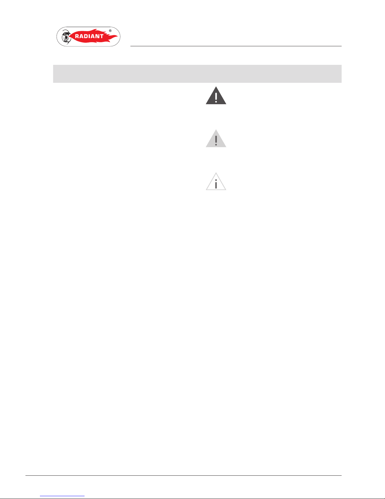
DANGER
It identifies information related to a
general danger that if not complied with, may cause
serious personal damage or even death.
ATTENTION
It identifies information that if not complied
with may cause small or medium level burns to the
person or serious damage to the boiler.
WARNING
It identifies a precaution information that
must be observed in order to avoid damaging the
machine or various parts.
MANUAL STORAGE
The manual must be stored carefully and replaced
in case of deterioration and/or low legibility.
If you misplace the use and maintenance manual,
you can request a copy from the Technical Support
Center. It is important to provide the model number
and serial number of the unit which is found on the
inside surface of the right panel.
INTRODUCTION
Page 5

5
R1K 34 /B - RAD - ING - Manuale - 1512.2_CSA_TTS
2.
MANUFACTURER WARRANTY AND
RESPONSIBILIT Y
The Manufacturer’s warranty is provided only
through its own authorized Technical Support
Centers, listed for each Region on the site
www.radianthydronics.com, and covers all
manufacturing defects at the time of sale.
The technical and functional features of the unit are
ensured when proper installation and miantenance
is carried out. Conditions of Manufacturer’s
warranty includes the following:
1. The customer is aware of and follows
instructions contained in the manuals that
accompany the product.
2. Annual service check up is required to keep
warranty valid.
3. The unit is installed and operated in the
conditions in which it is designed to.
For more information on the warranty validity,
its duration, the obligations and the exemptions,
please consult the First start-up certificate
attached to this manual.
The manufacturer reserves:
› the right to modify the tools and relative
technical documentation without any obligation
to third parties;
› the material and intellectual ownership of
this manual and forbids its distribution and
duplication, even partial, without prior written
authorization.
PRODUCT CONFORMITY
RADIANT BRUCIATORI spa with reference to
ANSI Z21.13-2014 • CSA 4.9-2014 GAS FIRED LOW
PRESSURE STEAM AND HOT WATER BOILERS,
declares that its gas boilers are professionally
manufactured.
The materials used such as copper, brass,
stainless steel create a homogeneous, compact
and functional assembly, easy to install and
maintain. The boiler is equipped with all
accessories necessary to provide a dependable
independent heating unit. All boilers are tested
and delivered with a quality certificate signed by
the testing department.
INTRODUCTION
Page 6

Page 7

The installation operations described in this section should
be performed only by qualified personnel, having the
appropriate technical training in the field for the installation
and maintenance of components of civil and industrial
domestic hot water production and heating plants.
1. INSTALLER SECTION
1. INSTALLER SECTION
Page 8

8
R1K 34 /B - RAD - ING - Manuale - 1512.2_CSA_TTS
1. INSTALLATION
INSTALLER
1.1. INSTALLATION
1.1.1. GENERAL INSTALLATION
WARNINGS
This boiler must be installed in accordance with
local codes, if any; if not, follow the National Fuel
Gas Code, ANSI Z223.1/NFPA 54, or the Natural
Gas and Propane Installation Code, CAN/CSA
B149.1, as applicable.
WARNING
This unit may be used only for the
purpose for which it has been designed: heat water
to a temperature below boiling point at atmospheric
pressure. Any other use is considered wrong and
dangerous. The manufacturer is excluded from
any contractual or out of contract responsibility for
damage caused to people, animals or property due
to errors during installation.
WARNING
This boiler should be installed only by
qualified service technician, having the appropriate
technical training in the field for the installation and
maintenance of components of civil and industrial
domestic hot water production and heating plants.
WARNING
After having removed the packing, make
sure the equipment is intact. In case of doubt, do not
use the equipment and contact the supplier.
BEFORE INSTALLING THE BOILER, THE
INSTALLER MUST MAKE SURE THAT THE
FOLLOWING CONDITIONS ARE PRESENT:
› The unit is connected to a heating plant and a
water supply network appropriate for its power
and performance.
› The location must be properly vented through
an air vent.
The air vent must be placed at floor level to prevent
it from being obstructed, protected by a grid that
does not hamper air flow.
› The unit is suitable for use with the type of
gas available by checking the boiler data plate
placed on the inner side of the front casing.
› Make sure that the gas lines are properly sealed
without any gas leaks.
› Make sure that the grounding system works
properly.
› Make sure that the electrical system is suitable
for the maximum power required by the
equipment, value indicated on the data plate.
WARNING
Use only original RADIANT optional or kit
accessories (including electrical).
1.1.2. BOILER LOCATION
ENVIRONMENTAL
REQUIREMENTS
The boiler shall be installed so the gas ignition
system components are protected from water
(dripping, spraying, rain, etc.) during appliance
operation and service (circulator replacement,
condensate trap, control replacement, etc.).
The boiler installed using inside air supply must
provide provisions for Combustion Air and
Ventilation Air in accordance with section 5.3, Air
for Combustion and Ventilation, of the National
Fuel Gas Code, ANSI Z 223,1/NFPA 54, or section
7,2, 7.3, or 7.4, of CAN/CSA B 149, Installation
Codes, or local codes having jurisdiction.
Where an exhaust fan or any other air consumption
appliance is installed in the same space as the
Page 9

9
R1K 34 /B - RAD - ING - Manuale - 1512.2_CSA_TTS
1. INSTALLATION
INSTALLER
boiler, sufficient air openings must be available to
provide fresh air when all appliances are operating
simultaneously. It is essential that in rooms
where the boiler is installed to provide as much
air as required by normal combustion of the gas
consumed by the varius appliances. Consequently,
it maybe necessary to make openings in the walls
to provide air inlet into the rooms.
Application where air from the structure is used
to supply combustion air for the unit, the following
openings are required:
1. Have a total free section of a least 25 mm2 every
kW (1 in2 for every 1000 Btu/hr) of heat input, with
a minimum of 100 cm2 (15.5 in2);
2. Where required by code or when required for
additional opening must be provided at the highest
practical elevation.
With a hermetically sealed combustion chamber
and air supply circuit from outdoors, the boiler may
be installed in any room in the home. Keep boiler
area clear and free from combustible materials,
gasoline and other flammable vapors and liquids.
WARNING
If the temperature in the boiler installation
location goes below 14°F centigrades, please fill
the system with anti-freeze liquid and insert and
electrical resistances kit (see 1.1.14 ‘ANTI-FREEZE
PROTECTION’).
1.1.3. REFERENCE LEGISLATION
This boiler must be installed in accordance with
local codes, if any; if not, follow the National Fuel
Gas Code, ANSI Z223.1/NFPA 54, or the Natural
Gas and Propane Installation Code, CAN/CSA
B149.1, as applicable.
Page 10

10
R1K 34 /B - RAD - ING - Manuale - 1512.2_CSA_TTS
1. INSTALLATION
INSTALLER
1.1.4. UNPACKING
WARNING
Please unpack the boiler just before
installing it. The Company is not responsible for
the damages caused to the device due to incorrect
storage.
WARNING
The packing elements (cardboard
box, wooden crate, nails, fasteners, plastic bags,
expanded polystyrene, etc.) are dangerous and must
be kept out of the reach of children, they should be
biscarded properly.
To unpack the boiler, proceed as follows:
› Place the packed boiler on the floor (fig. 1-A)
and remove the fasteners opening the four flaps
of the box outwards.
› Turn the boiler at 90° holding it with your hand
(fig. 1-B).
› Lift the box (fig. 1-C) and remove the guards (fig.
1-D).
C
B
D
A
fig. 1
Page 11
11
R1K 34 /B - RAD - ING - Manuale - 1512.2_CSA_TTS
1. INSTALLATION
INSTALLER
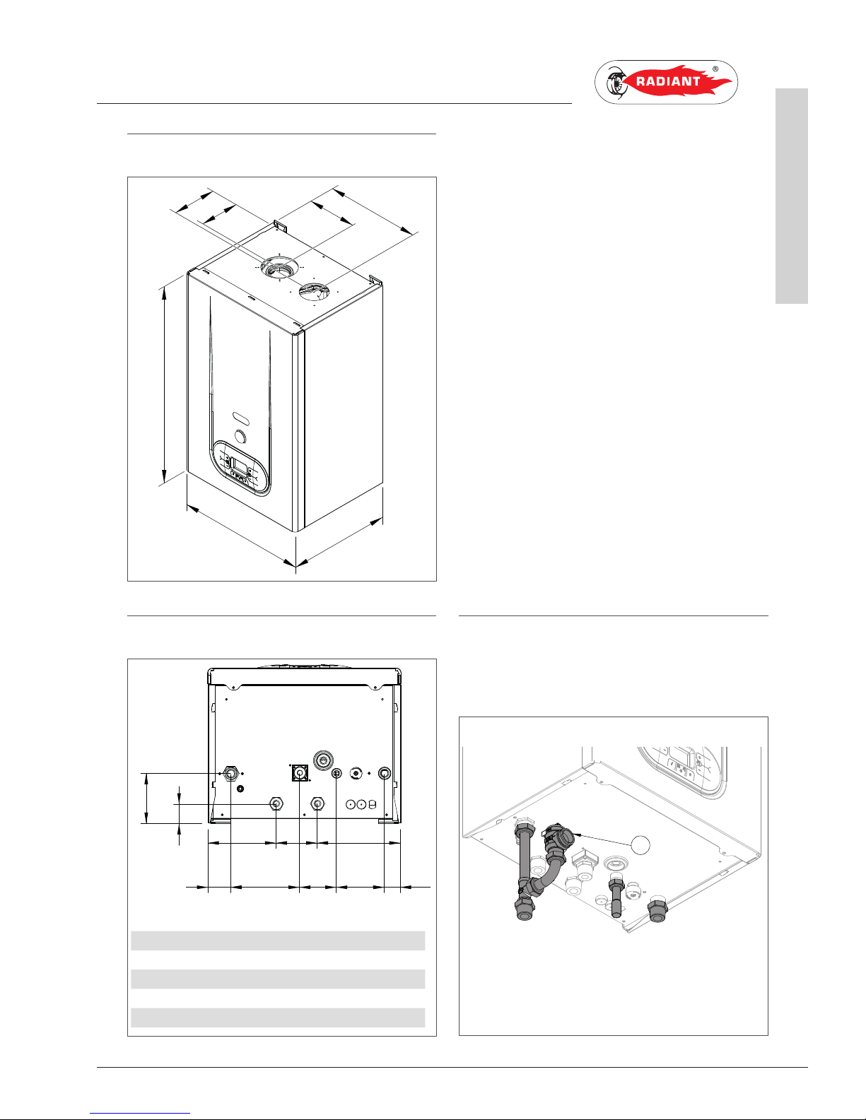
1.1.5. OVERALL DIMENSIONS (inch)
1.1.6. PIPING LAYOUT/IDENTIFICATION 1.1.7. HYDRAULIC CONNECTION KIT
An hydraulic kit equipped is available and supplied
by RADIANT upon demand.
11.8
6.1
5.3
5.9
12.9
16
25.2
1.9 5.8 3.1 4 1.2
5.7 6.9
1.6
4.2
R
RB
G F A
AB
3.4
VS
R F
A
fig. 2
fig. 3
fig. 4
R- RETURN Ø 3/4
G- GAS Ø 3/4 NPT
F- COLD Ø 1/2
A- INFEED Ø 3/4
RB- REMOT E D.H.W. CYLINDER RETURN Ø 3/4 NPT
AB- REMOTE D.H.W. CYLINDER FLOW Ø 3/4 NPT
R - CENTRAL HEATING RETURN Ø 3/4 NPT
F - COLD WATER INLET Ø 1/2 SWEAT
A - CENTRAL HEATING SUPPLY Ø 3/4 NPT
Page 12
12
R1K 34 /B - RAD - ING - Manuale - 1512.2_CSA_TTS
1. INSTALLATION
INSTALLER
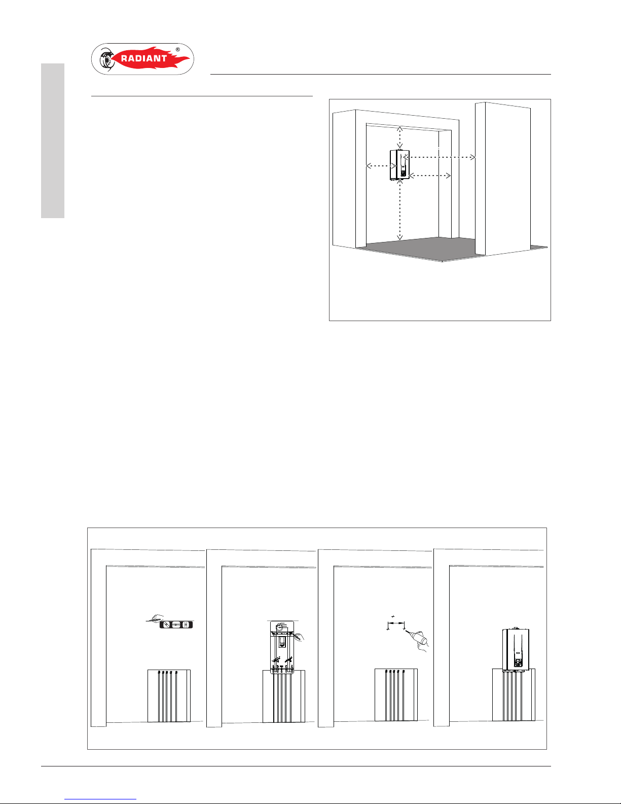
1.1.8. POSITIONING AND
CLEARANCES TO
COMBUSTIBLE MATERIAL AND
SERVICE CLEARANCES
The boiler must be installed only on a vertical solid
wall, able to sustain its weight.
This boiler has been certified to be installed with
“0” clearances to combustible material.
In order to allow the access inside the boiler for
maintenance operations, follow the minimum
service clearances indicated in figure 5.
To facilitate the installation, the boiler is provided
with a jig that allows setting in advance the
connections to the tubes providing the ablility
of connecting the boiler to completed masonry
structure.
To position the unit, proceed as follows (see fig. 6):
1. Trace a line using a spirit level (min. length 9.8 inch) on the installation wall.
2. Place the top of the jig along the traced line respecting the distances of the water connections; then
mark the two points to insert the fasteners, then trace the points for the exhaust vent;
3. Remove the jig and drill the wall;
4. Fix the wall bracket using the screws provided. Hang the unit on the bracket.
3
1
42
70 80 10249 3178
Ø80
Ø125
Ø100
35826 26
54 54
821
681
699
302
785
H
B
A
Y
X
A - 7.8 inch
B - 11.8 inch
X - 2.3 inch
Y - 2.3 inch
H - 36 inch
fig. 5
fig. 6
Page 13

13
R1K 34 /B - RAD - ING - Manuale - 1512.2_CSA_TTS
1. INSTALLATION
INSTALLER
WARNING
Using a level, make sure the boiler is
properly level (see fig. 6) to allow the condensate to
drain.
1.1.9. CIRCULATOR PERFORMANCE CURVES
fig. 7
UPSO 15-58 AOKR
III
II
I
H (ft)
Q (US gpm)
0 2 4 6 8 10
22
20
18
16
14
12
10
8
6
4
2
0
PRE VALENCE (m)
FLOW RATE US gpm
III
Circulator priority maximum speed
- - - - Appliance Loss fig. 8
Page 14
14
R1K 34 /B - RAD - ING - Manuale - 1512.2_CSA_TTS
1. INSTALLATION
INSTALLER
1.1.10. WATER CONNECTIONS
DANGER
Make sure that the tubes of the water and
heating unit are not used as grounding system for the
electrical unit. There are not suitable for such use.
WARNING
To prevent voiding the warranty and to
ensure the proper operation of the boiler, wash the unit
(if possible when hot) with suitable descaling solution to
remove the impurities coming from tubes and radiators.
WARNING
If the boiler is installed in a hydrostatic
position lower than those of the user devices (radiators,
fan coils, etc.), mount the shut-off valves on the domestic
water heating circuit to ease the performance of the
maintenance operations if necessary to only empty the
boi ler.
WARNING
When connecting the equipment to water
supply, avoid excessive bending and recovery operations
from improper positioning that may damage the tubes
causing leaks, malfunction or premature wear.
WARNING
In order to avoid any vibrations and noises, do
not use tubes with small diameters or elbows with small
radius and significant cut-off of the passage sections.
DOMESTIC CIRCUIT
In order to prevent limestone build-up and damages
to the domestic water heat exchanger, the hardness
of the domestic supply water should not exceed 8.4°
dh (degrees hardness). However, please check the
characteristics of the water used and install suitable
treating devices.
The heat exchanger coil cleaning frequency depends
on the hardness of the supply water and on the
presence of solid residues or impurities inside
the water that are often present in case of recently
installed plants. Based on the characteristics of
the inlet water, you should install suitable water
treatment devices, for residues presence. Please
install an inline filter.
The pressure of the cold inlet water should be
between 7.2 psi (0.5 bar) and 150 psi (10.34 bar). In
case of greater pressure values, please install a
pressure reducer upstream from the boiler.Please
refer to local jurisdictions on the requirements for
cold inlet water pressure.
HEATING CIRCUIT
In order to avoid any scale or deposits on the primary
exchanger, the hardness of the heating circuit inlet
water should not exceed 14° dh (degrees hardness).
However, please check the characteristics of the
water used and install suitable treatment devices.
To protect the central heating system from damaging
corrosion, flakes or deposits it is important to clean
the hydronic system using cleaners such as Fernox F3
Cleaner. For long term protection against corrosion
and deposits, the use of inibitor (such as Fernox F1
inhibitor) is required after cleaning and flushing of
the hydronic system. It is important to monitor the
concentration of the inibitor during commisioning and
during servicing of unit.
WARNING
Failure to clean the central heating system
or add adequate inibitor invalidates the compliance
warranty.
Connect the boiler safety drains (heating circuit safety
valve) to a discharge funnel. The manufacturer is not
responsible for any floods due to safety valve opening
in case of unit excessive presure build up.
WARNING
In case the boiler is installed as part of a low
temperature circuit, please install a safety thermostat
on the heating flow, which can stop the boiler activity
in case of high heating flow temperature. The company
assumes no liability for damage caused to persons or for
failure to comply with these instructions.
Page 15
15
R1K 34 /B - RAD - ING - Manuale - 1512.2_CSA_TTS
1. INSTALLATION
INSTALLER
1.1.11. PRESSURE RELIEF VALVE KIT
To complete the installation of the boiler, you must
install an approved 3/4”, maximum 30 PSI (2 bar)
pressure relief valve on the heating return.
A hydronic kit equipped with hydronic connections
and safety valve (see ‘VS’ fig. 9) is available and
supplied by RADIANT.
ATTENTION
The pressure relief valve MUST TO BE
INSTALLED in any case.
ATTENTION
The pressure relief valve should be placed
as close to the boiler as possible. No other valve
should be placed between the pressure relief valve
and the boiler.
DANGER
Improper installation of the pressure
relief valve may result in property damage, personal
injury, or death. Follow all instructions and guidelines
when installing the pressure relief valve. The valve
should be installed only by a licensed professional.
When installing the valve, follow these guidelines:
› Direct the discharge piping of the pressure relief
valve so that hot water will not splash on anyone
or any nearby equipment.
› Attach the discharge line to the pressure relief
valve and run the end of the line to within 6-12”
(150-300mm) of the floor.
› Ensure that the discharge line will allow free and
complete drainage without restriction. Do not
install a reducing coupling or other restriction
on the discharge line.
VS
R F
A
fig. 9
Page 16
16
R1K 34 /B - RAD - ING - Manuale - 1512.2_CSA_TTS
1. INSTALLATION
INSTALLER
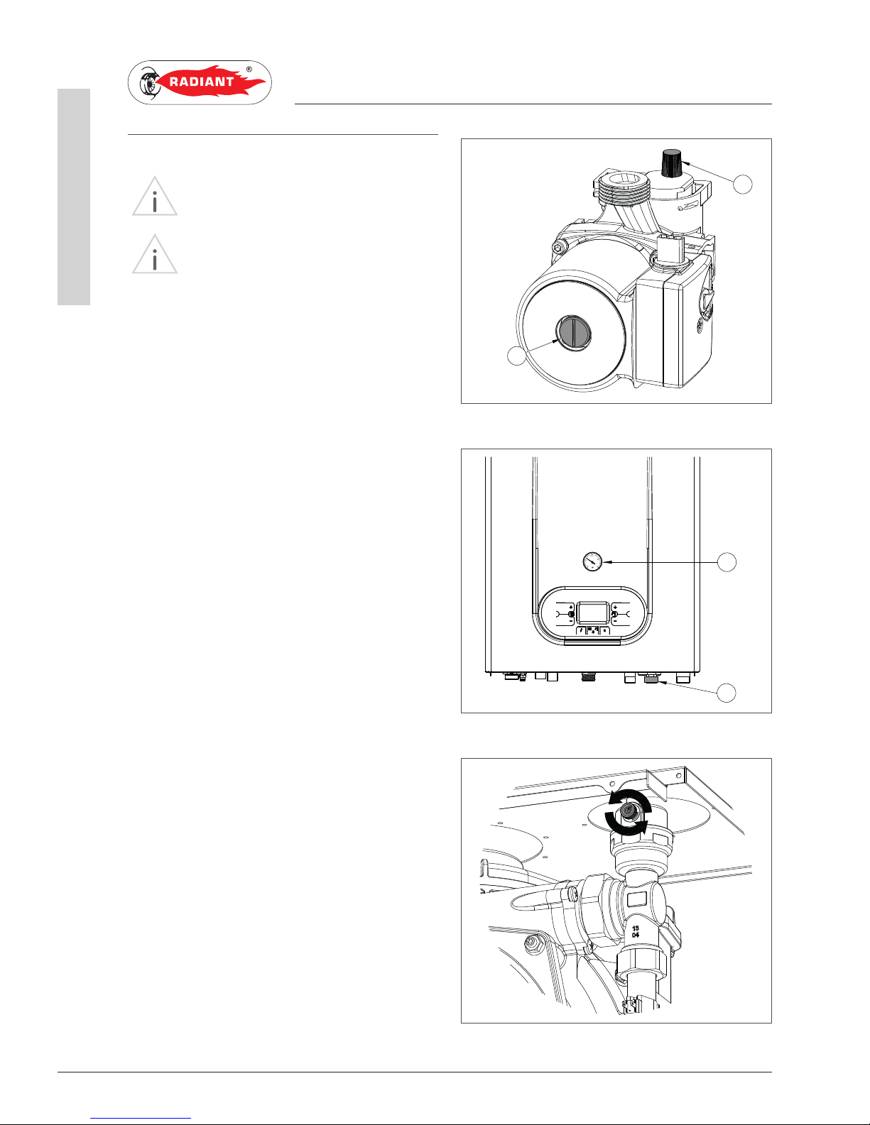
1.1.12. SYSTEM FILLING
WARNING
For system filling use only clean tap water.
WARNING
If the system is filled by adding ethylene
glycol-type chemical agents it is suggested to install
a system fender on the hydronic system in order to
separate the heating circuit from the domestic circuit.
Before powering up the boiler, fill the system as
follows:
1. Make sure the circulator is not blocked;
2. Slightly loosen the cap of the circulator air
eliminator (1-fig. 10) to release the air from
the system;
3. Slightly loosen the cap of the air eliminator
placed on the top of the condensing block
(fig. 12) to release the air form the top of the
system;
4. Open the feeding tap “R” (fig. 11);
5. Release all the air;
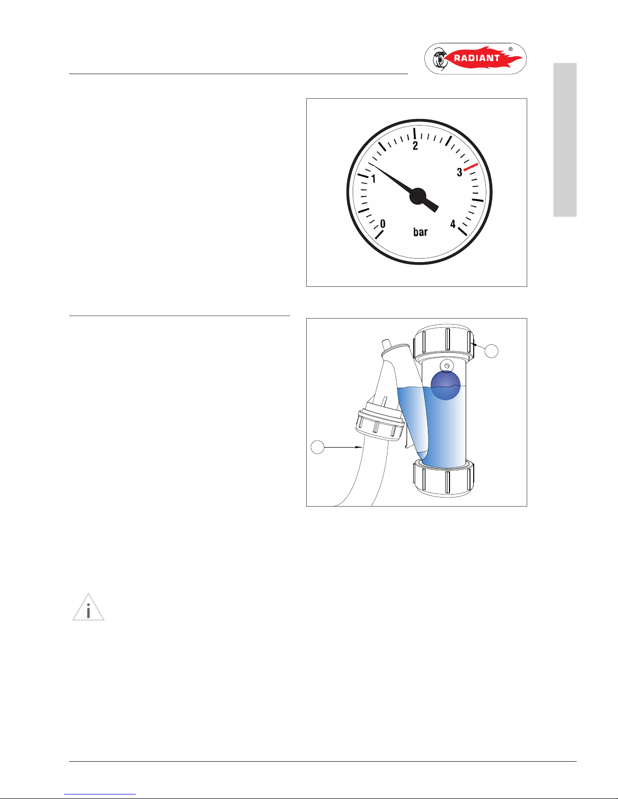
6. Use pressure gauge “M” (fig. 11) to make sure
that the system pressure reaches 1.2 bar (fig.
13);
7. After performing this operation, make sure
that the loading tap “R” (fig. 12) is properly
closed.
1
2
M
R
fig. 10
fig . 11
fig. 12
Page 17
17
R1K 34 /B - RAD - ING - Manuale - 1512.2_CSA_TTS
1. INSTALLATION
INSTALLER
8. Unscrew the circulator cap (2-fig.10) to release
any air bubbles and close it to prevent water
leakage;
9. Open the air relief valves of the radiators and
check the air removal process. When the
water starts to leak close the radiators air
relief valves.
10. If after performing these operations you
observe a decrease of the water pressure
inside the system, open once again the loading
tap “R” until the pressure gauge indicates the
value of 1.2 bar (fig. 13)
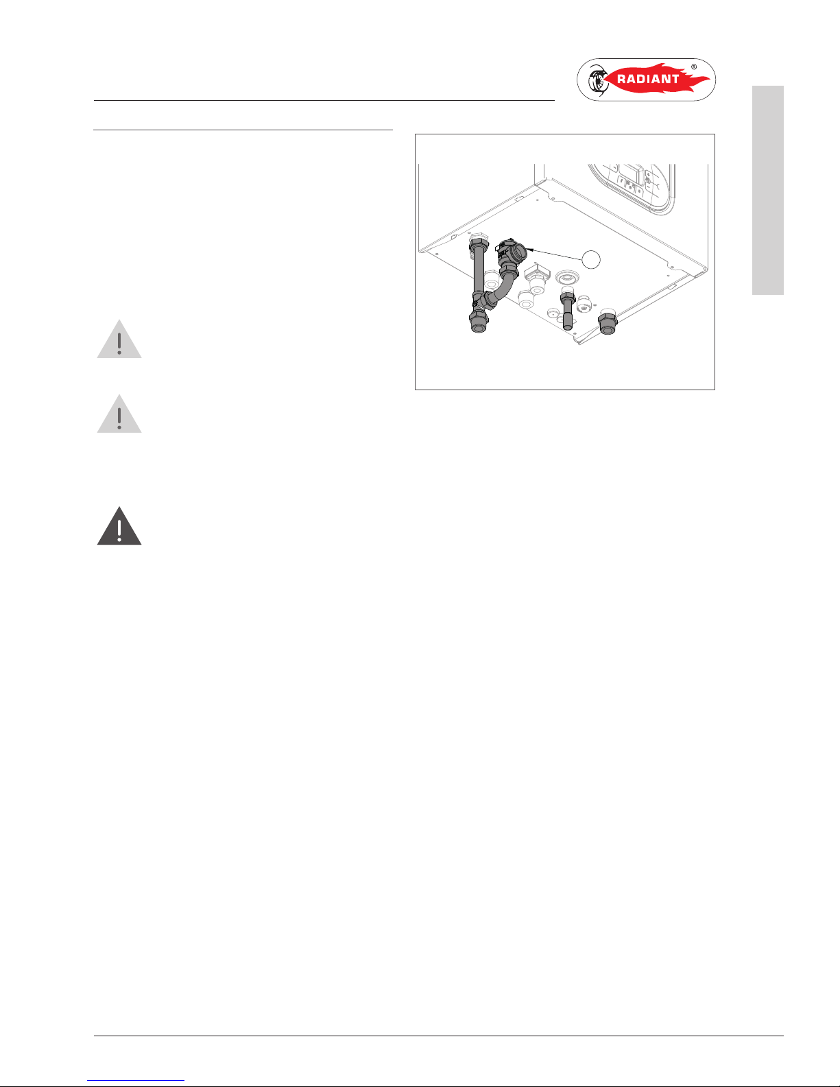
1.1.13. FILLING THE CONDENSATE
COLLECTION SIPHON
Before starting the boiler you have to fill the
condensate collection siphon in order to avoid fuel
back up through the siphon.
Fill the condensate collection siphon as follows
(see fig. 14):
› Unscrew the “T” cap from the siphon, fill three
quarters of the the siphon with water and screw
the “T” cap back in;
› Connect the dedicated flexible condensate
draining tube “P” to a waste disposal system.
The condensate can be drained directly in the
sewer system by inserting an easily serviceable
siphon.
WARNING
After the fir st months of boiler operation,
it is recommended to clean the condensate trap, to
eliminate possible deposits coming from the first
flow of the condensate inside the boiler technical
components. These deposits could cause a
malfunctioning of the trap.
P
T
fig. 13
fig. 14
Page 18

18
R1K 34 /B - RAD - ING - Manuale - 1512.2_CSA_TTS
1. INSTALLATION
INSTALLER
CONDENSATE DRAIN
The boiler produces a significant amount of
condensate during operation. This condensation
has an acidic pH of 3-5. Follow all local codes and
regulations when disposing of condensate from
the boiler.
The project engineer should consider the
possibility of installing systems to eliminate the
acidic condensation, according to system power
and buildings’ use.
The system should be designed to avoid
the condensate freezing. Before the boiler
commissioning, check the correct condensate
flow.
WARNING
Check before connecting the condensate
trap to the drain pipe, for the proper
gradient of boiler as described in paragraph “1.1.8
POSITIONING AND MINIMAL TECHNICAL SPACES”.
WARNING
Properly connect the siphon condensate
from the boiler to a drain system having adequate
slope. Where possible, you should make this
connection using transparent tubing to check for
proper condensate drainage and avoid stagnation that
could cause hazardous backflow of the condensate
into the boiler.
To connect the condensate drain use only
corrosion-resistant material for the drain line.
CONDENSATE NEUTRALIZER KIT
The condensate neutralization system neutralizes
the condensate created by the products of
combustion.
Acid condensate, introduced into the neutralization
box, follows a two-step set course. First phase:
nitrates and sulphates filtration through active
carbons contained in the first part of the carbon
site pipe. In the second phase the pH rises.
The acidity of the condensate can be controlled
through the use of appropriate tools for the
determination of Ph, such as the litmus paper.
Neutralized condensate can then be routed to the
drainage system.
MAINTENANCE
The pH value of the condensate after the neutralizer
must be in between <5,5 – 9,5>.
Every six months, you need to determine the pH of
the condensate treated in the neutralizer. Litmus
paper or a digital instrument can be used to
measure the pH level.
Neutral point is on the 6,8-7 value; in case of lower
value the condensate is acid, in case of a higher
value it is basic.
If necesssary, replace the active carbon and the
reagent granulate.
Page 19

19
R1K 34 /B - RAD - ING - Manuale - 1512.2_CSA_TTS
1. INSTALLATION
INSTALLER
1.1.14. ANTI-FREEZE PROTECTION
The boiler is protected against freezing using the
electronic board design with a function that start
the burner and heat the water in the boiler when
their water temperature goes below the minimum
pre-set values, protecting the boiler up to an
external temperature of 14 °F (-10 °C).
The device starts when the hot water temperature
goes below 41 °F (5 °C), automatically starting the
burner until the water reaches the temperature of
86 °F (30 °C).
The system starts even if display appears “OFF”,
as long as the boiler is connected to the power (120
V) and gas supply.
For long periods of standby, please empty the
boiler and the plant.
If the temperature goes below 14 °F (-10 °C)
centigrades, please fill the plant with anti-freeze
liquid (CLEANPASS FLUIDO AG cod. 98716LA)
and insert and electrical resistances kit (cod. 65-
00200).
DILUTION PERCENTAGE OF CLEANPASS
FLUIDO AG
ANTIFREEZE ETHYLENE GLYCOL
TEMPERATURE
FREEZING POINT
(%) VOLUME °F (°C)
20 18 (-7.5 )
30 8.6 (-13)
35 -0. 4 (-18)
40 -8.5 (- 22.5)
45 -18 (-28)
50 -28 (-33.5)
55 -44 (-42)
60 -58 (-50)
RECOMMENDED MINIMUM PERCENTAGE OF
GLYCOL : 20 %
Page 20

20
R1K 34 /B - RAD - ING - Manuale - 1512.2_CSA_TTS
1. INSTALLATION
INSTALLER
1.1.15. GAS CONNECTION
WARNING
The gas piping must be installed according
to all local and state codes, or in absence of local and
state codes, with the latest “Natural gas and propane
installation code”, CAN/CSA-B 149.1 or “National
Fuel Gas Code”, ANSI Z223.1 (NFPA 54). Consult
the “Natural gas and propane installation code” or
“National Fuel Gas Code” for the recommended gas
pipe size of other materials.
BEFORE PERFORMING THE GAS CONNECTION,
MAKE SURE THAT:
› The gas line size and length meets requested;
› The gas line is equipped with all safety and
control devices required by the standards in
force;
› The internal and external seals of the gas inlet
lines of the plant are checked;
› The device is suitable for use with the type of
gas available by checking the boiler data plate
(located on the inner side of the front casing. If
they do not match you must take the necessary
measures to adapt the boiler to another type of
gas (see 2.2.18 CONVERSION TO A DIFFERENT
GAS TYPE);
› The gas supply pressure falls within the values
indicated on the data plate.
1.1.16. ELECTRICAL CONNECTION
DANGER
The equipment is electrically safe only
if it is properly connected to an efficient grounding
system, performed in compliance with the safety
standards in force (National Electrical Code, ANSI/
NFPA 70 and or the Canadian Electrical Code Part
I, CSA C22.1, Electrical Code). You should check this
essential safety requirement. If in doubt, request an
accurate check of the electrical system performed by
qualified staff, as the manufacturer is not responsible
for any damages caused by lack of grounding system.
› Make sure that the electrical systems is
suitable for the maximum power consumed by
the equipment, value indicated on the data plate.
› Make sure that the cables section is appropriate
for the maximum power consumed by the
equipment.
› The equipment works with alternating current
of 120 V and 60 Hz. The electrical connection
must be installed using an all-pole switch with
an opening of at least 0.12 in (3 mm) between
contacts placed upstream from the device.
WARNING
Make sure that the phase and neutral
cables connection is installed in compliance with the
wiring diagram (see 1.1.17 POWER SUPPLY).
WARNING
It is strictly forbidden to use adaptors,
multiple plugs and/or extensions for the general
power supply of the equipment from the electrical
supply.
Page 21

21
R1K 34 /B - RAD - ING - Manuale - 1512.2_CSA_TTS
1. INSTALLATION
INSTALLER
1.1.17. POWER SUPPLY
To power the boiler connect the electrical cables
to the terminal inside the control panel as follows:
DANGER
Cut off the voltage from the main switch.
› remove the boiler's front casing (refer to 2.2.13
ACCESSING THE BOILER).
› loosen the two screws and remove the plate “A”
(see fig. 15).
› after removing the plate, connect the electrical
cables to terminal “B” (see fig. 15):
· the yellow/green cable to the terminal marked
with grounding symbol “ ”.
· the blue cable to the terminal marked with
“N”.
· the brown cable to the terminal marked with
“ L”.
After performing these operations, remount plate
“A” and the front casing.
Note: A 3-prong plug is provide with every unit and
the above wiring has been performed.
L
N
SeSe
A
TaTa
B
fig. 15
WHITE
YELLOW/GREEN
BLACK
Page 22
22
R1K 34 /B - RAD - ING - Manuale - 1512.2_CSA_TTS
1. INSTALLATION
INSTALLER
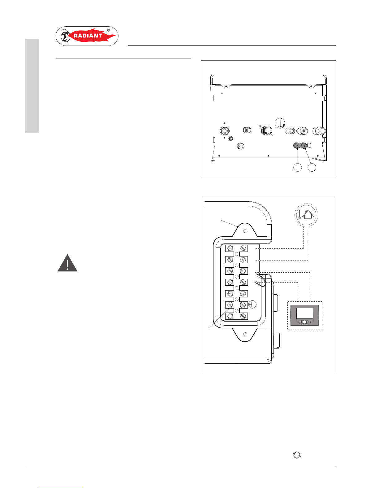
1.1.18. OPTIONAL ELECTRICAL
CONNECTIONS
The cables should be inserted inside the boiler
using the cable glands ‘P1’ and ‘P2’ placed under
the board (see fig. 16). Make a hole on the cable
gland, smaller than the cable diameter, to make
sure that the air cannot pass through.
To wire the options below:
• (SE) EXTERNAL TEMPERATURE PROBE COD.
73518L A
• (TA) ENVIRONMENT THERMOSTAT
• (CR) REMOTE CONTROL OPEN THERM COD. 4000017
use the terminal placed inside the control panel
as follows:
DANGER
Shutoff the voltage from the main switch.
› Remove the front casing of the boiler (see 2.2.13
ACCESSING THE BOILER); unscrew the screws
and remove plate “A” (see fig. 16-B).
› After removing the plate, connect the electrical
cables to terminal “B” (see fig. 16-B):
· For the external temperature Probe connect
the two non-polarized conductors to the SeSe contacts.
· For the environment Thermostat or Remote
control, first remove the bridge on the TaTa contacts and then connect the two nonpolarized conductors to the Ta-Ta contacts.
After performing these operations, remount plate
“A” and the front casing.
NB: In case of simultaneous presence of external probe and
remote control, the modulation board only sends the external
temperature value to the remote device without using it for
modulation.
The communication between board and remote control takes
place independently from the boiler’s operating mode and after
establishing the connection, the used interface on the board is
disabled and the display shows the symbol ‘ ’.
P1 P2
L
N
SeSe
A
TaTa
B
SE
TA
CR
fig. 16-B
fig. 16
Page 23
23
R1K 34 /B - RAD - ING - Manuale - 1512.2_CSA_TTS
1. INSTALLATION
INSTALLER
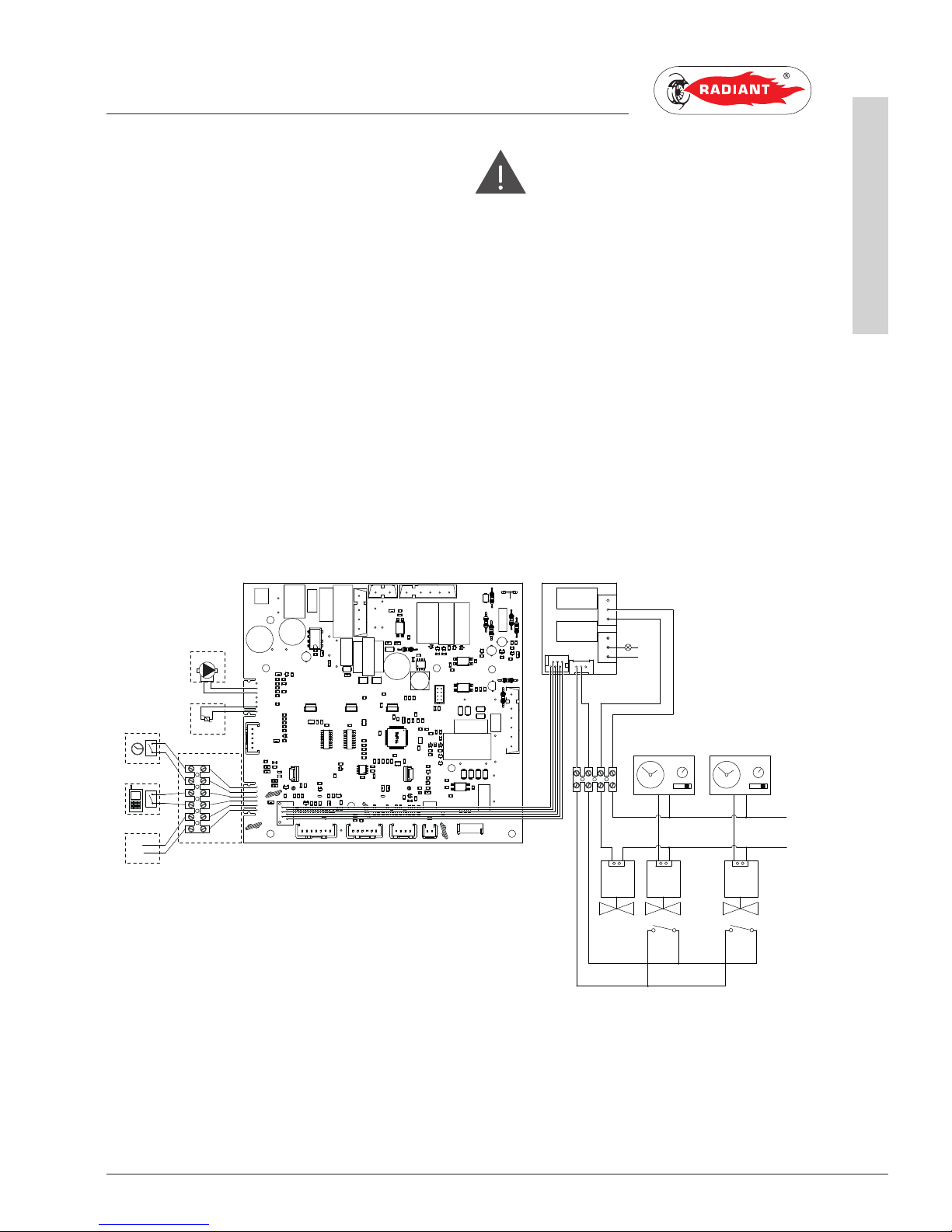
To wire the options below:
• (PM) MODULATING PUMP
• (TP) DOMESTIC HOT WATER PRE-HEATING
DEACTIVATION TIMER
• (CT) TELEPHONE DIALER
• BUS 0-10V
• (SVZ) CONTROL BOARD FOR AREA VALVES
CONNECTED TO A REMOTE CONTROL COD. 6500030
Use the electronic board placed inside the control
panel as follows:
DANGER
Shutoff the voltage from the main switch.
› Remove the boiler's front casing (refer to 2.2.13
ACCESSING THE BOILER).
› Remove the crankcase of the control panel (see
2.2.14 ACCESSING THE ELECTRONIC BOARD).
› After removing the crankcase, connect the
items below to the electronic board (see fig. 17):
After performing these operations, remount the
crankcase and the front casing.
TP
CT
BUS 0-10V
GND
BUS+
11
10
98
7
12
13
14
15
16
17
M12
M9
M7
M5
M2
M4
M8
M10
M15
M16
1
2
3
4
57
61
60
59
58
4443424140
39
38
3736353433
32
31
30
29
28
27
26
MIAH4
bl
br
PM
SR
62
63
64
65
66
67
68
51
52
53
54
55
56
5
6
M13
M14
o
o
bk
bk
bl
br
120 V - 60 Hz
L
N
VZR
VZ2 VZ1
FC FC
TAZ 2
TAZ 1
SRB
N
1
2
3
4
5
6
9 8
7
M1
M4
M2
M3
SVZ
L
gy
o
r
bk
COD.40-00133
fig. 17
SR: RETURN PROBE FC: AREA VALVES LIMIT SWITCH
SRB: REMOTE LED FOR SIGNALLING BOILER LOCKOUT GY: G RE Y
TAZ1: ENVIRONMENT THERMOSTAT AREA 1 O: ORANGE
TAZ 2: ENVIRONMENT THERMOSTAT ARE A 2 BK: BLACK
VZ1: AREA 1 VALVE BR: BROWN
VZ2: ARE A 2 VALVE BL: LIGHT BLUE
VZR: REMOTE CONTROLLED AREA VALVE R: RED
Page 24
24
R1K 34 /B - RAD - ING - Manuale - 1512.2_CSA_TTS
1. INSTALLATION
INSTALLER
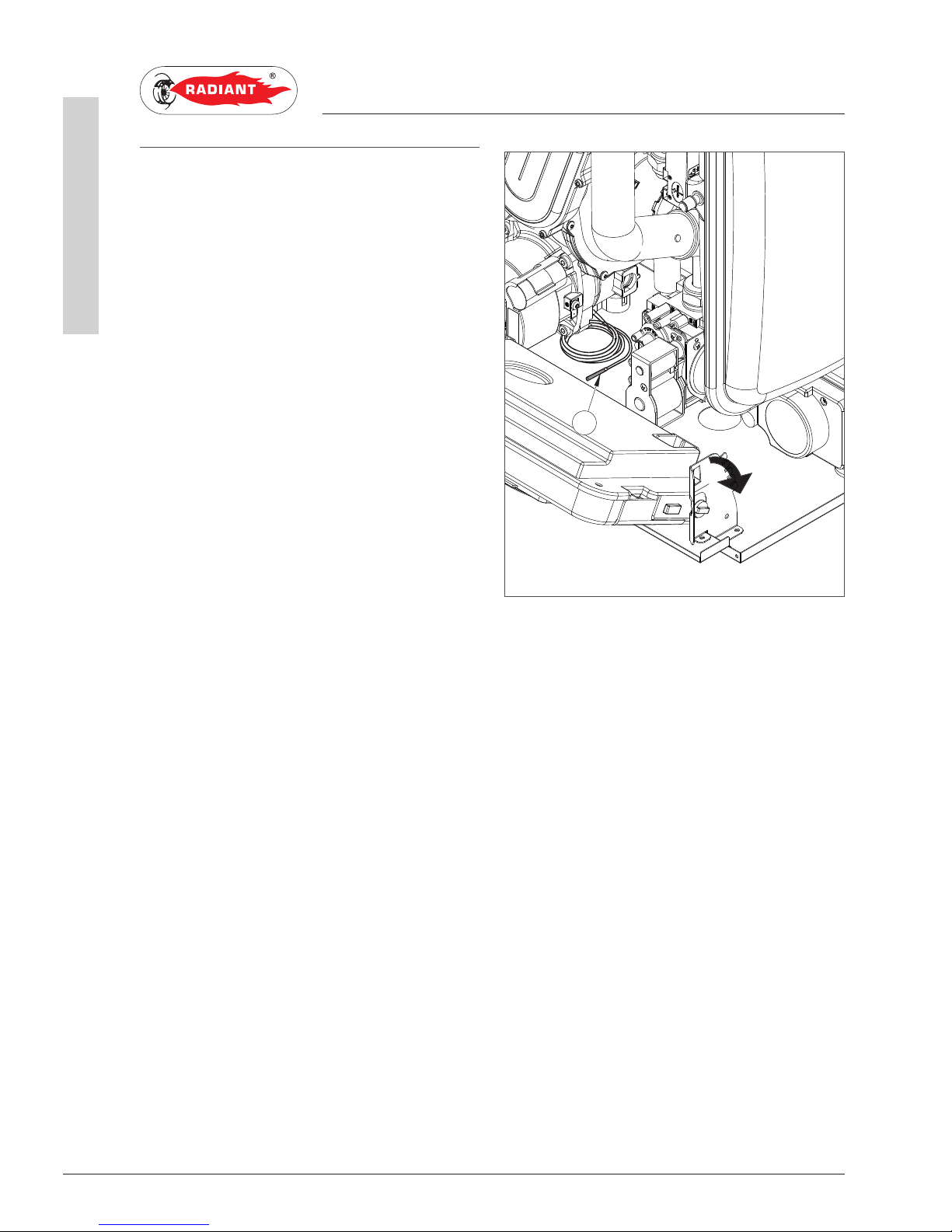
1.1.19. DHW SENSOR INSTALLATION
To install the DHW sensor inside the remote water
tank, please proceed as follows:
Remove the boiler front case panel (see Paragraph
ACCESSING THE BOILER);
Grasp the left and right control panel support
brackets and pull them outwards, at the same
time rotating the panel downwards;
Take the 8 m. length DHW sensor cable (see
C-figure), located onto the boiler bottom plate,
and insert the sensor inside the water tank sensor
holder.
Once this operation has been completed, rotate
the control panel upwards and install the front
case panel back to its original position.
C
Page 25

25
R1K 34 /B - RAD - ING - Manuale - 1512.2_CSA_TTS
1. INSTALLATION
INSTALLER
1.1.20. VENTING
WARNING
In order to ensure proper operation and
efficiency of the device you have to connect the
boiler fume exhaust fitting to the exhaust and fresh
air adapters (loosely supplied in water heaters). It is
recommended to install discharge systems approved
by Radiant.
WARNING
All termination kits must be located and
installed in accordance with local building code and
CSA B149.1 Natural Gas and Propane Installation
Code.
WARNING
For condensate collection please follow
the local codes.
› All exhaust runs shall be sloped such that any
condensate would move towards the combustion
chamber so that it can be collected and drained
via the internal condensate trap of the appliance
(Refer to section 1.1.20).
› All combustion air intake runs where possible
should be sloped in a manner to avoid rain
water, dust or foreign objects from entering the
appliance (Refer to section 1.1.20).
› In case of horizontal polypropylene co-axial
system installation, properly orientate the
horizontal co-axial terminal in relation to the
slopes inside the exhaust pipe and to protect
the combustion air pipe from adverse weather
conditions (Refer to section 1.1.20, sub-section
III (a) and figure 20).
This appliance is certified to be installed using
polypropylene, PVC and CPVC. For Canada use
System 636 polypropylene, PVC and CPVC Type
BH Gas Venting Systems certified to ULC S636.
Types of venting configurations for this appliance
are, co-axial vent (pipe with in a pipe), co-linear
vent (separate pipes for exhaust and combustion
air), and single exhaust vent (uses room air for
combustion).
Page 26

26
R1K 34 /B - RAD - ING - Manuale - 1512.2_CSA_TTS
1. INSTALLATION
INSTALLER
TABLE MINIMUM DISTANCE feet mm
A- below openable window or
door
3* 900*
B- below ventilation opening
(non mechanical)
3* 900*
C- below soffits 1 300
D- below balcony 1 300
E- from adjacent window or
door
3* 900*
F- from adjacent ventilation
opening (non mechanical)
3* 900*
G- from horizontal or vertical
soil or drain pipes
1 300
H- from corner of building 1 300
I - from recess in building 1 300
L - above a paved sidwalk or a
paved driveway that is located
on public property
7 2100
M- between two terminals set
vertically
2 600
N- between two terminals set
horizontally
2 600
(*)- FOR APPLIANCE WITH INPUTS UP TO
AND INCLUDING 100,000 Btu/h (29.3 kW) THIS
DISTANCE REDUCES TO 1 ft (300 mm).
1. The vent shall not terminate:
a) where it may cause hazardons frost or ice
accumulations on adjacent property surfaces;
b) less that 7 ft (2.1 m) above a paved sidewalk or a
paved driveway that is located on public property;
c) within 6 ft (1.8 m) of a mechanical air-supply
inlet to any building;
d) above a regulator wi thin 3 ft (900 mm) horizontally
of the vertical centerline of the regulator vent outlet
to a maximum vertical distance of 15 ft (4.5 m);
e) within 3 ft (900 mm) of any gas service regulator
vent outlet;
f) less than 1 ft (300 mm) above grade level plus
expected snow level;
g) within the following distances of a window or
door that can be opened in any building, of any
non-mechanical air supply inlet to any building, or
of any combustion air inlet of any other appliance;
· i) 12 in (300 mm) for inputs up to and including
100,000Btu/h.
· ii) 3 ft (900 mm) for inputs exceeding 100,000
Btu/h.
h) Underneath a veranda, porch, or deck unless;
· i) the veranda, porch, or deck is fully open
on a minimum of two sides beneath the floor;
and
· ii) the distance between the top of the vent
termination and the underside of the veranda,
porch, or deck is greater than 1 ft (300 mm);
2. Building material within 5 ft (1,5m) of a vent
terminal will be subjec ted to products of combustion
and therefore may be subject to discoloration or
deterioration, of building materials.
fig. 18
Page 27

27
R1K 34 /B - RAD - ING - Manuale - 1512.2_CSA_TTS
1. INSTALLATION
INSTALLER
1.1.21. TYPES OF EXHAUST SYSTEMS
GENERAL INTRODUCTION
The venting installation must conform to the
requirements of the authority having jurisdiction or,
in the absence of such requirements, to the National
Fuel Gas Code, ANSI Z223.1/NFPA 54, and/or Natural
Gas and Propane Installation Code, CAN/CSA B149.1.
Horizontal exhaust runs shall slope upwards not less
than 1/4 in/ft [21 mm/m] from the boiler to the vent
terminal. Venting shall be installed so as to prevent
the accumulation of condensate throughout the vent
run. Provide means for drainage of condensate on all
vertical exhaust runs and where necessary.
Horizontal combustion air intake runs should slope
downwards not less than 1/4 in/ft [21 mm/m] from
the boiler to the air intake terminal where possible.
For installations in which the combustion air run
cannot slope to the outdoors, it is recommended that
a trap be installed closed to the appliance (see figure
‘H’).
Where not possible a water trap shall be installed so
as to collect moisture or water from entering into the
air box of the boiler. Provide means for drainage of
moisture and water on all vertical air intake runs and
where necessary.
Traps, if used, should have pipe slopes not less
than 1/4 in/ft [21 mm/m] downwards to the trap.
I - CO-LINEAR VENT (FRESH AIR AND EXHAUST)
The Gas-Fired wall mounted hot boilers can be
installed with two separate pipes. The two separate
pipes consists of one for the exhaust an the other for
combustion air intake.
Please refer to Table 1: Allowable vent lengths for
maximum vent and combustion air intake runs.
Co-linear vent installations can be either be installed
through the wall or through the roof.
I (a) - THROUGH THE WALL LNSTALLATION:
Through the wall installations can terminate with two
separate pipes or with a concentric terminal.
Please refer to figure ‘A’ for installations using
terminations using co-linear vent.
Refer to figure ‘B’ for installations using co-linear
vent with co-axial terminal.
INSULATED
EXHAUST
12” minimum12” minimum
TRAP
6”minimum
Exhaust
Air Intake
12” minimum
12” minimum
above average
snow fall
Air Intake
Distance above avg.
snow fall or grade
Ref: CSA B149.1
Exterior wall
1” Min
2” Max
(From wall
or Face Plate)
Clamp or Strap
(Field Supplied)
Exhaust
Air Intake
Exhaust
fig. A
fig. B
fig. H
Page 28

28
R1K 34 /B - RAD - ING - Manuale - 1512.2_CSA_TTS
1. INSTALLATION
INSTALLER
I (b) - THROUGH THE ROOF LNSTALL ATION:
Through the roof installations can terminate with
two separate pipes or with a co-axial terminal.
Please refer to figure ‘C’ for installations using colinear vent with vertical termination.
Refer to figure ‘D’ for installations using a colinear vent with vertical co-axial terminal.
II - SINGLE VENT
This gas-fired wall mounted hot boilers can be
installed with one single vent pipe for exhaust.
Please refer to Table 1: Allowable vent lenghts for
maximum vent run.
Single vent installations can be either be installed
through the wall or through the roof.
II (a) - THROUGH THE WALL INSTALLATION:
Please refer to figure ‘E’ for through the wall single
vent installations.
II (b) - THROUGH THE ROOF INSTALLATION:
Please refer to figure ‘F’ for through the roof single
vent installations.
12” minimum
12” minimum
Roof
Exhaust
12” minimum
above average
snow fall
Air
Intake
Air Intake
Distance above avg.
snow fall or grade
Ref: CSA B149.1
Flashing
(Field Supplied)
Roof
Clamp or Strap
(Field Supplied)
Exhaust
Air Intake
Exhaust
12” minimum
above average
snow fall
Roof
Exhaust
12” minimum
above average
snow fall
fig. C
fig. D
fig. E
fig. F
Page 29

29
R1K 34 /B - RAD - ING - Manuale - 1512.2_CSA_TTS
1. INSTALLATION
INSTALLER
AIR INTAKE / FLUE EXHAUST Ø 3” (80 MM)
ADAPTORS WITH PP TEST POINT (COD.: 65-
00433)
These adapters are to be installed on co-linear vent
(two separate pipes for exhaust and combustion
air), and single exhaust vent (using room air for
combustion). Additional bushings or couplings are
required to transition from 3” schedule 40 pipe
to 2” or 4” schedule 40 pipe only for installations
using 2” or 4” schedule 40 pipe. Additional
transition adapters are not needed for installations
using only 60 mm or 80 mm polypropylene, or 3”
schedule 40 PVC or CPVC pipe.
Ensure that the adapters are installed correctly
into the correct locations as per the attached
figure 19.
Installation instructions:
· Remove the air intake cover plate.
· Clean the inspection collar surface and the
area of the air intake hole.
· Stick the appropriate neoprene gaskets onto
the underside of the mounting flange of the
adapters. Pay attention to aligning the four
mounting through holes.
· Mount the intake/flue exhaust adaptors with
self tapping screws provided with the flue kit.
· Install the first piece of 60 mm or 80 mm
polypropylene or 3” schedule 40 PVC or CPVC
pipe until it bottoms out.
· Finally use the gear clamp to tighten the first
piece of pipe to the adaptor.
cod.: 65-00433
FLUE EXHAUST
COMBUSTION AIR INTAKE
fig. 19
Page 30

30
R1K 34 /B - RAD - ING - Manuale - 1512.2_CSA_TTS
1. INSTALLATION
INSTALLER
III (a) - KIT M&G HORIZONTAL CO-AXIAL
SYSTEM Ø3.1/4.9 in (Ø80/125 mm) INTERNAL
POLYPROPYLENE DUCT ADJUSTABLE AT 360°.
It allows exhaust and air intake from external wall.
Suitable only for condensing unit.
It allows exhaust and air intake for combustion
through co-axial ducts, the external one for air
intake, the plastic internal one for exhaust.
PLEASE SEE THE MAXIMUM EXHAUST LENGTH
IN THE TABLE IN 1.1.21 “ALLOWABLE VENT
LENGTHS”.
The maximum exhaust length (or linear reference
length) can be calculated by summing the length
of the linear tube.
When terminating horizontally, install an elbow at
the end of the terminal. For area where snow is
a concern it is recommended to point the elbow
downwards.
90°
L= 3.9 in(100 mm)
Ø4.9 in (Ø125 mm)
Ø3.1 in (Ø80 mm)
fig. 20
fig. 21
Page 31

31
R1K 34 /B - RAD - ING - Manuale - 1512.2_CSA_TTS
1. INSTALLATION
INSTALLER
III (b) - KIT M&G VERTICAL CO-AXIAL
SYSTEM Ø3.1/4.9 in (Ø80/125 mm) INTERNAL
POLYPROPYLENE DUCT.
It allows exhaust and air intake directly from roof.
Suitable only for condensing boilers.
It allows exhaust and air intake for combustion
through co-axial ducts, the external one for air
intake, the plastic internal one for exhaust.
PLEASE SEE THE MAXIMUM EXHAUST LENGTH
IN THE TABLE IN 1.1.21 “ALLOWABLE VENT
LENGTHS”.
The maximum exhaust length (or linear reference
length) can be calculated by summing the length
of the linear tube.
Ø4.9 in (Ø125 mm)
Ø3.1 in (Ø80 mm)
fig. 22
fig. 23
Page 32

32
R1K 34 /B - RAD - ING - Manuale - 1512.2_CSA_TTS
1. INSTALLATION
INSTALLER
1.1.22. TABLE 1: ALLOWABLE VENT LENGTHS
Vent
Configuration Pipe Size
Minimum
Length
Vertical and
Horizontal
for Vent Run
Max
Equivalent
length Vertical
and Horizontal
for vent run Gas Type Exhaust Vent Intake Vent
Co-axial vent Ø2.3/3.9”
(Ø60/100
mm)
1 ft (0.3 m) +
elbow
19 ft (6 m) +
elbow*
Natural or
Propane
Polypropylene Polypropylene
Co-linear vent
(2 Separate
pipes)****
2” (60 mm) 3.3 ft (1 m) 65 ft (20 m)** Natural or
Propane
PVC, CPVC,
Polypropylene
PVC, CPVC,
Polypropylene, ABS
Co-linear vent
(2 Separate
pipes)****
3” (80 mm) 3.3 ft (1 m) 150 ft (46 m) Natural or
Propane
PVC, CPVC,
Polypropylene
PVC, CPVC,
Polypropylene, ABS
Single vent 2” (60 mm) 1.6 ft (0.5 m) 36 ft (11 m)*** Natural or
Propane
PVC, CPVC,
Polypropylene
PVC, CPVC,
Polypropylene, ABS
Single vent 3” (80 mm) 1.6 ft (0.5 m) 100 ft (30 m) Natural or
Propane
PVC, CPVC,
Polypropylene
PVC, CPVC,
Polypropylene, ABS
* The domestic fan maximum speed adjustment (P11) must be changed to a value of 198 Hz and the heating fan
maximum speed adjustment (P13) must be changed to a value of 183 Hz with a total vent run of above 10 ft (3 m).
** The domestic fan maximum speed adjustment (P11) must be changed to a value of 198 Hz and the heating fan
maximum speed adjustment (P13) must be changed to a value of 183 Hz with a total vent run of above 22 ft (7 m).
*** The domestic fan maximum speed adjustment (P11) must be changed to a value of 198 Hz and the heating fan
maximum speed adjustment (P13) must be changed to a value of 183 Hz with a total vent run of above 19 ft (6 m).
**** Vent run consists of allowable vent length for exhaust pipe and an additional allowable vent length for combustible
ai r.
NOTE: In Canada, exhaust vent must be approved to ULC S636 standard.
EQUIVALENT LENGTHS
Each 2”/ 3” (60 mm / 80 mm) 45° elbow equates to 2.5 linear feet to vent pipe.
Each 2”/ 3” (60 mm / 80 mm) 90° short radius elbow equates to 7.5 linear feet to vent pipe.
Each 2”/ 3” (60 mm / 80 mm) 90° long radius elbow equates to 5 linear feet to vent pipe.
Each Ø2.3/3.9” (Ø60/100 mm) co-axial 90° short radius elbow equates to 5 linear feet to vent pipe.
The total maximum equivalent vent pipe distance cannot exceed the maximum length listed for horizontal
and vertical venting distance. The maximum lengths are not including elbows unless otherwise stated.
Exceeding the maximum venting distances will cause the appliance to malfunction or cause an unsafe
condition.
Page 33

All operations described below relative to first start-up,
maintenance and replacement and should be performed
only by qualified service technician.
1. SUPPORT CENTER SECTION
2. SEZIONE CENTRO ASSISTENZA
Page 34

34
R1K 34 /B - RAD - ING - Manuale - 1512.2_CSA_TTS
2. FIRST START-UP
SUPPORT CENTER
2.1. FIRST START-UP
2.1.1. PRELIMINARY OPERATIONS
FOR FIRST START-UP
The first start-up operations consist of checking
the correct installation, adjustment and operation
of the device. Proceed as follows:
› Check the inner components and ensure
that they are sealed in accordance with the
specifications provided and by standard and
regulations.
› Check if the gas used is suitable for the boiler;
› Check if the gas capacity and relative pressures
comply with those on the rating plate;
› Check the operation of the safety device in case
of lack of gas;
› Make sure that the device supply voltage
corresponds with that on the plate (120 V – 60
Hz) and that the wiring is correct;
› Make sure that the grounding system works
properly;
› Make sure that the combustion air circulation,
exhaust and condensate discharge take place
properly in compliance with the Local and
National Laws and Standards in force;
› Make sure that the venting and their connections
and comply with the requirements of the Local
and National Laws and Standards;
› Make sure that the heating system valves are
open;
› Make sure that there is no intake of gaseous
products within the system;
› Make sure that there are no flammable liquids
or materials near the device;
› Open the boiler gas valve and make sure that
there are no gas leaks upstream from the device
(the burner gas connection must be checked
while the unit is running);
› In case of new installation of the gas supply
network, the air inside the gas line may lockout
the device at first start-up. Repeat the start-up
procedure to purge all the air inside the gas line.
Page 35

35
R1K 34 /B - RAD - ING - Manuale - 1512.2_CSA_TTS
2. FIRST START-UP
SUPPORT CENTER
2.1.2. BOILER COMMISSIONING
WARNING
Make sure that the system is correctly
filled.
Proceed with boiler commissioning as follows:
› Power the boiler.
THE START-UP SYSTEM WILL AUTOMATICALLY
ACTIVATE THE SYSTEM AIR RELIEF CYCLE
FUNCTION DISPLAYED ON SCREEN WITH CODE
“F33” (ONLY AT FIRST START-UP WILL LAST FOR
5 MINUTES). When function “F33” is active, the
pump is enabled and the burner start-up request
is disabled. The boiler can work normally only
after completing the operation.
NOTE: Only at the first start-up the system relief
cycle performed by the boiler lasts 5 minutes.
After each water pressure reset the boiler will
automatically perform a reduced system relief
cycle, of 2 minutes. Throughout this function the
display will show the code “F33”. The boiler can
work normally only after completing the operation.
› Open the gas valve.
› Use the button ‘ ’ to select the desired
operation mode. If the symbol is displayed fixed,
it means that the function was activated.
› The burner will start as soon as the thermostat
contact is closed;
› If the flame is not sensed, the board will repeat
the start-up operations after post-ventilation
(20 seconds).
› You might have to repeat the start-up operation
several times to release all air inside the gas
lines. Before repeating the operation, wait at
least 5 seconds from the last start-up attempt
and unlock the boiler from “E01” error code by
pressing the Reset ‘ ’ key.
Page 36

36
R1K 34 /B - RAD - ING - Manuale - 1512.2_CSA_TTS
2. FIRST START-UP
SUPPORT CENTER
2.1.3. CO2 VALUE CHECK AND
CALIBRATION
WARNING
The CO2 value should be measured with
the casing assembled, while the gas valve could only
be adjusted with the casing open.
To check and calibrate the CO2 value to minimum
and maximum heating power proceed as follows:
FOR MINIMUM HEATING POWER
› Enable chimney-sweep function holding the key
‘ ’ for 7 seconds (maximum operating time is
15 minutes), then press key ‘ ’ of the heating
circuit to set minimum power for heating
function, the display will show ‘Lo’.
› Insert the combustion analyser probe in the
provided exhaust tap ‘PF’ (fig. 24), then make
sure that the CO2 value complies with the
requirements indicated in 2.2.8 “Technical data”,
otherwise adjust using screw ‘A’ (fig. 25) and
adjust using a 4 Allen wrench the screw ‘2’ (fig.
25) of the Off-Set adjuster. To increase the CO
2
value, turn the screw clockwise and counterclockwise if you want to decrease it.
› Once completed the adjustment, tighten the
protection screw ‘A’ (fig. 25) on the Off-Set
adjuster.
FOR MAXIMUM HEATING POWER
› Press key ‘ ’ of the heating circuit to
set maximum power for heating function, the
display will show ‘HI’.
› Make sure that the CO2 value complies with the
indications in 2.2.8 “Technical data”, otherwise
adjust using screw ‘1’ (fig. 25) of the gas flow
adjuster. To increase the CO2 value, turn the
screw counter-clockwise and clockwise if you
want to decrease it.
› After each adjustment variation on screw ‘1’
(fig. 25) of the gas flow adjuster you have to wait
for the boiler to stabilize itself to the set value
(about 30 seconds).
› Then press key ‘ ’ of the heating circuit
to set minimum power for heating function and
check that CO2 value hasn’t changed, in case
it has changed, please repeat the setting as
described previously.
› Press the button ‘ ’ to deactivate the
chimney sweep function.
PF
1
2
A
fig. 24
fig. 25
Page 37

37
R1K 34 /B - RAD - ING - Manuale - 1512.2_CSA_TTS
2. FIRST START-UP
SUPPORT CENTER
2.1.4 . ACCESSING AND PROGRAMMING THE PARAMETERS
To access the parameters menu and adjust their values, follow the procedure below:
1. Press the button ‘ ’ to select the OFF
mode displayed using the symbol ‘ ’.
2. Hold at the same time the keys ‘ ’ and ‘
’ until on the display appears the symbol ‘
’with the message ‘P00’, and release the keys
‘ ’ and ‘ ’.
3. Use the keys ‘ ’ and ‘ ’ of the heating
circuit to select the parameter to be edited.
fig. 26
fig. 27
fig. 28
Page 38

38
R1K 34 /B - RAD - ING - Manuale - 1512.2_CSA_TTS
2. FIRST START-UP
SUPPORT CENTER
4. Use the keys ‘ ’ and ‘ ’ of the domestic
circuit to change the value of the parameter.
5. Press the key ‘ ’ to confirm the action and
wait for the display to stop blinking, indicating
the adjustment was implemented.
6. To exit the parameters menu, hold at the same
time the keys ‘ ’ and ‘ ’ and wait for the
symbol ‘ ’ to appear on the display.
fig. 29
fig. 30
fig. 31
Page 39

39
R1K 34 /B - RAD - ING - Manuale - 1512.2_CSA_TTS
2. FIRST START-UP
SUPPORT CENTER
2.1.5. DIGITECH CS (MIAH402) PARAMETERS TABLE
PARAMETER DESCRIPTION RANGE FUNCTION
P00 BOILER MODEL SELECTION 0 - 10 0 - 7 = N.A.
8 = R2K 24 - R2KA 24/8
9 = R2K 34 - R2KA 34/2 0 - R1K 34/B
10 = R1K 55-R2K 55
P01 BOILER TYPE SELECTION 0 - 5 0 = INSTANTANEOUS > R2K
1 = N.A.
2 = ACCUMULATION (STORAGE)>
R1K /B - R2K A
3 = ACCUMULATION (STORAGE)
COMFORT > R1K /B - R2K A
4 = INSTANTANEOUS COMFORT -
FAST H2O> R2K
5 = HEATING ONLY> R1K 55
P02 GAS TYPE SELECTION
ATTENTION:
REA D THE INST RUCTION IN 2 .2.19 ‘CONVER SION TO A DIFF ERENT
GAS T YPE’ BEFOR E CHANGING THIS PAR AMETER.
0 - 1 0 = NATUR AL GAS (AND SE TS FAN
SPEED SETTING AT PARAMETERS
P10 - P11 - P12 - P13)
1 = PROPANE (AND SETS FAN
SPEED SETTING AT PARAMETERS
P10 - P11 - P12 - P13)
P03 SETTING THE HEATING TEMPERATURE
IN CASE THE BOILER IS INSTALLED AS PART OF A LOW
TEMPERATURE CIRCUIT, PLE ASE INSTALL A SAFET Y
THERMOSTAT ON THE HE ATING FLOW, WHICH CAN STOP
THE BOILER ACTI VIT Y IN CASE OF HIGH HEATING FLOW
TEMPERATURE. THE COMPANY ASSUMES NO LIABILITY FOR
DAMAGE CAUSED TO PERSONS OR FOR FAILURE TO COMPLY
WITH THESE INSTRUCTIONS.
0 - 1 0 = STANDARD 86-176 °F (30-80 °C)
(SET BY DEFAULT)
1 = REDUCED 77-113 °F (25-45 °C)
FOR FLOOR SYSTEMS
Page 40

40
R1K 34 /B - RAD - ING - Manuale - 1512.2_CSA_TTS
2. FIRST START-UP
SUPPORT CENTER
PARAMETER DESCRIPTION RANGE FUNCTION
P04 HEATING RUN-UP
THROUGH THIS PARAMETER YOU CAN SET THE TIME, DURING
START-UP PHASE, NECESS ARY FOR THE BOILER TO REACH THE
MA XIMUM SE T POWER (ON THE HEATING SIDE).
0 - 4 0 = (DISA BLED)
1 = 50 SECONDS
(SET BY DEFAULT)
2 = 100 SECONDS
3 = 200 SECONDS
4 = 400 SECONDS
P05 ANTI-WATER HAMMER SELECTION
ONCE THIS FUNCTION IS ENABLED, THE DHW CONTACT WILL BE
DELAYED FOR A TIME EQUAL TO THE SET VALUE.
0 - 20 0 = DISA BLED
1 - 20 = THE VALUE IS EXPRESSED
IN SECONDS
P06 DOMESTIC CIRCUIT PRESERVATION FUNCTION
(ONLY FOR INSTANTANEOUS BOILER)
THROUGH THIS PARAMETER YOU CAN PRESERVE THE
CIRCUL ATOR THE DIVERTER VALVE IN DOMESTIC POSITION
FOR A PERIOD OF TIME EQUAL TO THE POST-CIRCULATION
(SEE PARAMETER P09), SO AS TO M AINTAIN THE SECONDARY
EXCHANGER HOT.
0 - 1 0 = DISA BLED
(SET BY DEFAULT)
1 = ENABLED
P07 HEATING TIMING
THROUGH THIS PARAMETER YOU CAN SET THE MINIMUM
TIME FOR WHICH THE BURNER WILL BE TURNED OFF ONCE
THE HE ATING TEMPERATURE REACHED THE USER SET
TEMPERATURE.
0 - 90 VALUE EXPRESSED IN MULTIPLES
OF 5 SECONDS
(PRE-SE T AT 36 X 5 = 180 SECONDS)
P08 POST-CIRCULATION HEATING TIMING
THROUGH THIS PARAME TER YOU CAN SET THE PUMP DURATION
OF OPER ATION DURING HEATING CYCLE, A FTER THE MAIN
BURNER T URNS OFF DUE TO THE ENVIRONMENT THERMOSTAT.
0 - 90 VALUE EXPRESSED IN MULTIPLES
OF 5 SECONDS
(PRE-SE T AT 36 X 5 = 180 SECONDS)
P09 POST-CIRCULATION DOMESTIC / BOILER TIMING
THROUGH THIS PARAMETER YOU CAN SET THE PUMP
OPER ATION DUR ATION ON THE DOMESTIC CIRCUIT, AFTER THE
TAP IS CLOSED.
0 - 90 VALUE EXPRESSED IN MULTIPLES
OF 5 SECONDS
(PRE-SE T AT 18 X 5 = 90 SECONDS)
Page 41

41
R1K 34 /B - RAD - ING - Manuale - 1512.2_CSA_TTS
2. FIRST START-UP
SUPPORT CENTER
PARAMETER DESCRIPTION RANGE FUNCTION
P10 DOMESTIC FAN MINIMUM SPEED ADJUSTMENT
THROUGH THIS PARAMETER YOU CAN SET THE FAN MINIMUM
SPEED IN DOMESTIC PHASE, THAT CORRESPONDS TO THE
MINIMUM BURNER POW ER DURING A REQUEST TO OPERATE
IN DOMESTIC MODE. [SEE 2.1.6 ‘COMBUSTION BLOWER
FREQUENCY/HEAT CAPACITY DIAGRAM’].
THE VALUE IS PRE-SE T BASED ON THE SET POWER (SEE
PARAMETER P00) A ND ON THE GAS T YPE (SEE PARAMETER P 02).
45 - VALUE
SET FOR
PARAMETER
P11
THE VALUE IS EXPRESSED IN
HERTZ
(1HZ = 30 RPM)
P11 DOMESTIC FAN MAXIMUM SPEED ADJUSTMENT
THROUGH THIS PARAMETER YOU CAN SET THE FAN MA XIMUM
SPEED IN DOMESTIC PHASE, THAT CORRESPONDS TO THE
MA XIMUM BURNER POWER DURING A REQUEST TO OPERATE IN
DOME STIC MODE [S EE 2.1.6 ‘C OMBUSTI ON BLOWER F REQUENCY/
HEAT CA PACIT Y DIAGR AM’].
THE VALUE IS PRE-SE T BASED ON THE SET POWER (SEE
PARAMETER P00) A ND ON THE GAS T YPE (SEE PARAMETER P 02).
VALUE
SET FOR
PARAMETER
P10 - 203
THE VALUE IS EXPRESSED IN
HERTZ
(1HZ = 30 RPM)
P12 HEATING FAN MINIMUM SPEED ADJUSTMENT
THROUGH THIS PARAMETER YOU CAN SET THE FAN MINIMUM
SPEED IN HEATING PHASE, THAT CORRESPONDS TO THE
MINIMUM BURNER POW ER DURING A REQUEST TO OPERATE IN
HEATING MODE. [SEE 2.1.6 ‘COMBUSTION BLOWER FREQUENCY/
HEAT CA PACIT Y DIAGR AM’].
THE VALUE IS PRE-SE T BASED ON THE SET POWER (SEE
PARAMETER P00) A ND ON THE GAS T YPE (SEE PARAMETER P 02).
45 - VALUE
SET FOR
PARAMETER
P13
THE VALUE IS EXPRESSED IN
HERTZ
(1HZ = 30 RPM)
P13 HEATING FAN MAXIMUM SPEED ADJUSTMENT
THROUGH THIS PARAMETER YOU CAN SET THE FAN MA XIMUM
SPEED IN HEATING PHASE, THAT CORRESPONDS TO THE
MA XIMUM BURNER POWER DURING A REQUEST TO OPERATE IN
HEATING MODE [SEE 2.1.6 ‘COMBUSTION BLOWER FREQUENCY/
HEAT CA PACIT Y DIAGR AM’].
THE VALUE IS PRE-SE T BASED ON THE SET POWER (SEE
PARAMETER P00) A ND ON THE GAS T YPE (SEE PARAMETER P 02).
VALUE
SET FOR
PARAMETER
P12 - 203
THE VALUE IS EXPRESSED IN
HERTZ
(1HZ = 30 RPM)
P14 STARTING STEP ADJUSTMENT
THROUGH THIS PARAMETER YOU CAN SET THE FAN SPEED
DURING START-UP.
THE VALUE IS PRE-SE T BASED ON THE SET POWER (SEE
PARAMETER P00) A ND ON THE GAS T YPE (SEE PARAMETER P 02).
VALUE
SET FOR
PARAMETER
P10 - 203
THE VALUE IS EXPRESSED IN
HERTZ (1HZ = 30 RPM) - (PRE-SET
AT 120 HZ)
Page 42

42
R1K 34 /B - RAD - ING - Manuale - 1512.2_CSA_TTS
2. FIRST START-UP
SUPPORT CENTER
PARAMETER DESCRIPTION RANGE FUNCTION
P15 ANTI-LEGIONELLA FUNCTION
(ONLY FOR ACCUMULATION BOILER)
THROUGH THIS PARAMETER YOU CAN ACTIVATE/DEACTIVATE
“ANTI LEGIONELL A” HEAT TRE ATMENT OF THE ACCUMULATION
BOILER. EVERY 7 DAYS THE WATER TEMPERATURE INSIDE THE
ACCUMULATION BOILER IS HEATED BE YOND 140 °F (60 °C) THUS
GENER ATING A BURNING HAZ ARD. KEEP UNDER CONTROL
SUCH DOMESTIC HOT WATER TRE ATMENT ( AND INFORM THE
USERS) TO AVOID UNFORESEEABLE DA MAGES TO PERSONS,
ANIMALS, PROPERT Y. A THERMOSTATIC VALVE SHOULD BE
INSTALLED AT THE DOMESTIC HOT WATER OUTLET TO AVOID
ANY BURNS.
0 - 1 0 = DISA BLED
1 = ENABLED (PRE-SET BY
DEFAULT ON ACCUMULATION
BOILERS)
Page 43

43
R1K 34 /B - RAD - ING - Manuale - 1512.2_CSA_TTS
2. FIRST START-UP
SUPPORT CENTER
PARAMETER DESCRIPTION RANGE FUNCTION
P16 CLIMATE COMPENSATION CURVE
(ONLY WITH EXTERNAL PROBE CONNECTED)
YOU CAN CONNECT AN EXTERNAL TEMPER ATURE PROBE (SEE
1.1.16 ‘ELECTRICAL CONNECTIONS’) THAT AUTOMATICALLY
CHANGES THE DELIVERY TEMPERATURE BASED ON THE
EX TERNAL MEA SURED TEMPERATURE. THE NATURE OF THE
CORRECTION DEPENDS ON THE THERMO-A DJUSTMENT VALUE
KD SET (SEE CHA RT).
THE SELECTION OF THE CURVE IS DETERMINED BY THE
MA XIMUM DELIVERY TEMPERATURE TM AND THE MINIMUM
EX TERNAL TEMPERATURE TE TAKING INTO ACCOUNT THE
HOUSE INSULATION DEGREE.
THE VALUES OF THE DELIVERY TEMPERATURES TM, REFER TO
STANDARD SYSTEMS 86-176 °F (30-80 °C) OR FLOOR SYSTEMS
77-113 °F (25-45 °C). THE SYSTEM TYPE CAN BE SET FROM
PARAMETER P03.
0 - 30 (SET BY DEFAULT AT 15) THE
NUMBERING OF THE VALUE
CORRESPONDS TO ‘KD’ CURVES
ON THE CHART (SEE CHART
BELOW).
P17 SETS THE TEMPERATURE MEASUREMENT UNIT
THROUGH THIS PARAMETER YOU CAN SET THE TEMPER ATURE
MEA SUREMENT UNIT DISPLAYED: CELSIUS (°C) OR FAHRENHEIT
(°F) DEGREES.
0 - 1 0 = °C
1 = °F
P18 ENABLING BUS INDUSTRIAL PILOTING 0 -10V
THROUGH THIS PARAMETER YOU CAN ENABLE OR DISABLE THE
BUS INDUSTRIA L INPUT 0-10 V TO SET THROUGH E XTERN AL BUS
THE BURNER POWER OR THE DELIVERY TEMPER ATURE.
0 - 2 0 = DISA BLED
(SET BY DEFAULT)
1 = TEMPERATURE CONTROL MODE
2 = POWER CONTROL MODE
Te (°F)
958677685950
167
176
113 MAX
Tm (°F)
41
32
23
14
149
131
140
122
104
113
95
86
86
5-4
77
MIN
95
158
Kd = 0
Kd = 5
Kd = 10
Kd = 15
Kd = 20
Kd = 25
Kd = 30
fig. 32
Page 44

44
R1K 34 /B - RAD - ING - Manuale - 1512.2_CSA_TTS
2. FIRST START-UP
SUPPORT CENTER
PARAMETER DESCRIPTION RANGE FUNCTION
P19 MINIMUM HEATING SETPOINT
THROUGH THIS PARAMETER YOU CAN SET THE USER-
ADJUSTABLE MINIMUM HEATING TEMPER ATURE.
20 - 40 THE VALUE IS EXPRESSED IN °C
P20 MAXIMUM HEATING SETPOINT
THROUGH THIS PARAMETER YOU CAN SET THE USER-
ADJUSTABLE MAXIMUM HEATING TEMPER ATURE.
40 - 90 THE VALUE IS EXPRESSED IN °C
P21 MAXIMUM DOMESTIC SETPOINT
THROUGH THIS PARAMETER YOU CAN SET THE USER-
ADJUSTABLE MAXIMUM DOMESTIC TEMPERATURE.
45 - 75 THE VALUE IS EXPRESSED IN °C
P22 SET POINT ∆T DELIVERY-RETURN
(ONLY WITH MODULATING PUMP AND RETURN PROBE CONNECTED)
THROUGH THIS PARAMETER YOU CAN SET THE TEMPER ATURE
DIFFERENCE BETWEEN DELIVERY AND RETURN.
0 0 = DISA BLED
10 - 40 THE VALUE IS EXPRESSED IN °C
P23 MODUL ATING PUMP MINIMUM SPEED
(ONLY WITH MODULATING PUMP AND RETURN PROBE CONNECTED)
THROUGH THIS PARAMETER YOU CAN SET THE MINIMUM SPEED
VALUE OF THE MODULATING PUMP DURING A REQUEST TO
OPER ATE IN HEATING MODE.
50 - 70 THE VALUE IS EXPRESSED IN
PERCENTAGE
P24 MODUL ATING PUMP MAXIMUM SPEED
(ONLY WITH MODULATING PUMP AND RETURN PROBE CONNECTED)
THROUGH THIS PARAMETER YOU CAN SET THE MAX IMUM
SPEED VALUE OF THE MODULATING PUMP DURING A REQUEST
TO OPER ATE IN HEATING MODE.
70 - 100 THE VALUE IS EXPRES SED IN
PERCENTAGE
P25 CONTROL PERIOD ∆T DELIVERY-RETURN
(ONLY WITH MODULATING PUMP AND RETURN PROBE CONNECTED)
THROUGH THIS PARAMETER YOU CAN SET THE RESPONSE TIME
TO THE PUMP MODULATION.
20 - 100 THE VALUE IS EXPRES SED IN
SECONDS
P26 OUTDOOR RESET FUNCTION 0 - 1 0 = 86-176 °F (30-80 °C)
1 = STANDARD RESE T FUNCTION
77-140 °F (25-60 °C) WITHOUT
OUTDOOR TEMPERATURE SENSOR
OR 86-176 °F (30-80 °C) WITH
OUTDOOR TEMPERATURE SENSOR
(SET BY DEFAULT).
Page 45

45
R1K 34 /B - RAD - ING - Manuale - 1512.2_CSA_TTS
2. FIRST START-UP
SUPPORT CENTER
2.1.6. COMBUSTION BLOWER FREQUENCY/HEAT CAPACITY DIAGRAM
GAS TYPE
MINIMUM
HEATING
FREQUENCY
MAXIMUM
HEATING
FREQUENCY
MINIMUM
FREQUENCY IN
DOMESTIC HOT
WATER LINE
MAXIMUM
FREQUENCY IN
DOMESTIC HOT
WATER LINE
N a t u r a l
Gas
Hz 43 182 43 182
Propane Hz 43 174 43 174
(btu/h)
Natural Gas
Propane
4
6
8
10
12
14
16
18
20
22
24
26
28
30
32
34
35 50 65 80 95 110 125 140 155 170 185
(kW)
13648
20472
27297
34121
40945
47769
54594
61418
68242
75067
81891
88715
95539
10236
10918
11601
(Hz)
fig. 33
Page 46

46
R1K 34 /B - RAD - ING - Manuale - 1512.2_CSA_TTS
2. MAINTENANCE
SUPPORT CENTER
2.2. MAINTENANCE
2.2.7. GENERAL MAINTENANCE
WARNINGS
ATTENTION
All maintenance operations must be
performed by qualified staff and authorized by
RADIANT BRUCIATORI spa.
WARNING
The maintenance operations must be
performed once every twelve months starting from
the boiler installation date.
WARNING
To ensure longer life span and proper
operation of the device, during the maintenance
operations use only original spare parts.
DANGER
Before each components cleaning or
replacement operation, ALWAYS cut off the POWER,
WATER and GAS supply of the boiler.
Please perform the following operations once a year:
› check the sealing of the gas components, and
replace the gaskets if necessary;
› check the sealing of the water components, and
replace the gaskets if necessary;
› visually check the flame and the condition of the
combustion chamber;
› if necessary make sure that the combustion is
adjusted correctly and if required proceed as
indicated in section 2.1.3 “CO2 VALUE CHECK AND
CALIBRATION”;
› remove and clean the burner from oxidation;
› check the integrity and the position of the sealed
chamber sealing gasket;
› check the primary exchanger, if necessary, clean
it;
› check the operation of the gas burner start up
and safety systems. If necessary, remove and
clean the flame detection and start up electrodes
from incrustations paying attention to respect the
distances with respect to the burner;
› check the heating circuit safety systems: limit
temperature safety thermostat; limit pressure
safety;
› check the pre-load pressure of the expansion tank;
› make sure that the permanent ventilation outlets
are present, correctly sized and functioning, based
on the installed devices. Follow the requirements
provided by Local and National legislation;
› periodically check the integrity of the venting
system for safety and proper operation;
› check that the wiring is installed in compliance with
the requirements in the boiler instruction manual;
› check the wiring inside the control panel;
› check the flow and temperature of domestic hot
water;
› check the proper operation of the condensate
draining system, including the devices outside
the boiler such as condensate collection
devices installed along the path of the venting or
neutralization devices for acid condensate.
› check that the liquid flow is not obstructed and
that there is on combustion gas build up inside the
internal system.
Page 47

47
R1K 34 /B - RAD - ING - Manuale - 1512.2_CSA_TTS
2. MAINTENANCE
SUPPORT CENTER
2.2.8. TECHNICAL DATA
Model R1K 34 /B
Maximum nominal heat capacity in heating circuit btu/h - (kW) 116013 - (34)
Maximum nominal heat capacity in domestic circuit btu/h - (kW) 116013 - (34)
Minimum nominal heat capacity in heating circuit btu/h - (kW) 15013 - (4.4)
Minimum nominal heat capacity in domestic circuit btu/h - (kW) 15013 - (4.4)
Useful thermal power - 140/176°F (60/80°C) btu/h - (kW) 113215 - (33.18)
Minimum useful thermal power - 140/176°F (60/80°C) btu/h - (kW) 14706 - (4.31)
Performance at 100% Pn - 140/176°F (60/80°C) % 9 7.6
Fumes temperature at nominal heat capacity °F - (°C) 161.96 (72.2)
Fumes temperature at minimum heat capacity °F - (°C) 144.68 (62.6)
CO2 at nominal heat capacity - Natural Gas min-max % 9.2 - 9.5
CO2 at minimum heat capacity - Natural Gas min-max % 8.9 - 9.2
CO2 at nominal heat capacity - Propane min-max % 10.3 - 10.6
CO2 at minimum heat capacity - Propane min-max % 10 - 10.3
CO at nominal heat capacity ppm 78
CO at minimum heat capacity ppm 1
Heating circuit
Adjustable heating temperature °F - (°C) 86-176 / 77-113
(30-80 / 25-45)
Maximum operating temperature for heating circuit °F - (°C) 203 - (95)
Maximum operating pressure for heating circuit psi - (bar) 60 - (4.1)
Minimum operating pressure for heating circuit psi - (bar) 4.29 - (0.3)
Expansion tank pre-charge pressure psi - (bar) 14,5 - (1)
Capacity of the system expansion vessel gal(US) - (litres) 2.11 - (8)
Domestic circuit
Adjustable domestic temperature °F - °C 95-140 (35-60)
Maximum pressure for domestic circuit psi - (bar) 150 - (10.34)
Minimum pressure for domestic circuit psi - (bar) 7.25 - (0.5)
Dimensional characteristics
Width in - (mm) 16.1 - (410)
Depth in - (mm) 12.9 - (330)
Height in - (mm) 25.27 - (642)
Gross weight lb - (Kg) 97 - (44)
Water connections
Flow NPT 3/4”
Cold water NPT 1/2”
Gas NPT 3/4”
Return NPT 3/4”
Electrical specifications
Voltage-frequency V/Hz 120/60
Max Absorbed Power W 78
Insulation rate IP X5D
Gas supply
Nominal supply pressure - Natural Gas psi - (mbar) 0.25 - (17.4)
Heating Max. fan speed - Natural Gas Hz 182
Page 48

48
R1K 34 /B - RAD - ING - Manuale - 1512.2_CSA_TTS
2. MAINTENANCE
SUPPORT CENTER
D.H.W Max fan speed - Natural Gas Hz 182
Heating Min. fan speed - Natural Gas Hz 43
D.H.W Min. fan speed - Natural Gas Hz 43
Fuel consumption - Natural Gas ft3/h - (m3/h) 114.41 - (3.24)
Nominal Supply pressure - Propane psi - (mbar) 0.47 - (27.4)
Heating Max. fan speed - Propane Hz 174
D.H.W Max fan speed - Propane Hz 174
Heating Min. fan speed - Propane Hz 43
D.H.W Min. fan speed - Propane Hz 43
Fuel consumption - Propane lb/h - (kg/h) 5.32 - (2.41)
Page 49

49
R1K 34 /B - RAD - ING - Manuale - 1512.2_CSA_TTS
2. MAINTENANCE
SUPPORT CENTER
2.2.9. TECHNICAL ASSEMBLYTECHNICAL ASSEMBLY
KEY
1. EXHAUST SAFETY THERMOFUSE
2. HEAT EXCHANGER
3. BURNER UNIT
4. IONIZATION ELECTRODE
5. COMBUSTION BLOWER
6. AIR ELIMINATOR
7. CIRCULATOR
8. GAS VALVE
9. SYSTEM DRAINING TAP
10. WATER TEMPERATURE HIGH LIMIT SWITCH
11. CENTRAL HEATING TEMPERATURE PROBE
12. SPARK ELECTRODE
13. THERMAL EXPANSION TANK
14. AIR SUCTION TUBE
15. IGNITION TRANSFORMER
16. PROPORTIONAL VENTURI
17. WATER PRESSURE TRANSDUCER
18. CONDENSATE COLLECTION SIPHON
19. DIVERTER VALVE
20. CHECK VALVE
21. SYSTEM FILLING TAP
1
2
3
4
5
6
7
8
9
6
10
11
12
13
15
16
17
19
18
21
20
14
fig. 34
Page 50

50
R1K 34 /B - RAD - ING - Manuale - 1512.2_CSA_TTS
2. MAINTENANCE
SUPPORT CENTER
2.2.10. INTERNAL PIPING
SCHEMATIC
KEY
R. CENTRAL HEATING RETURN
C. DOMESTIC HOT WATER OUTLET
G. GAS INLET
SC. CONDENSATE DRAIN
F. COLD WATER INLET
A. CENTRAL HEATING SUPPLY
1. EXHAUST SAFETY THERMOFUSE
2. HEAT EXCHANGER
3. BURNER UNIT
4. COMBUSTION BLOWER
5. GAS VALVE
6. AIR ELIMINATOR
7. CIRCULATOR
8. PRESSURE RELEIF VALVE 30 psi (2 bar)
9. SYSTEM DRAINING TAP
10. PRESSURE RELEIF VALVE 150 psi (10.3 bar)
11. DOMESTIC TEMPERATURE PROBE
12. INDIRECT TANK
13. CENTRAL HEATING TEMPERATURE PROBE
14. WATER TEMPERATURE HIGH LIMIT SWITCH
15. THERMAL EXPANSION TANK
16. AIR SUCTION TUBE
17. PROPORTIONAL VENTURI
18. WATER PRESSURE TRANSDUCER
19. CONDENSATE COLLECTION SIPHON
20. BY-PASS
21. DIVERTER VALVE
22. SYSTEM FILLING TAP
23. THERMAL EXPANSION TANK D.H.W.
24. CHECK VALVE
R
F
RB
A
10
11
12
AB
C
F
23
G
1
2
3
4
6
7
9
8
6
13
14
15
16
17
18
20
21
22
sc
5
19
24
fig. 35
Page 51

51
R1K 34 /B - RAD - ING - Manuale - 1512.2_CSA_TTS
2. MAINTENANCE
SUPPORT CENTER
2.2.11. 3-WAY VALVE OPERATION
Important: The working position of the 3-way valve
is indicated by the color (Red or Blue) visible in the
inside of the valve. (see ‘C’ - fig. 36).
› The RED color (with C-A) indicates the operation
in the Domestic Hot water mode.
› The BLUE color (with C-B) indicates the
operation in Heating mode.
C
fig. 36
Page 52

52
R1K 34 /B - RAD - ING - Manuale - 1512.2_CSA_TTS
2. MAINTENANCE
SUPPORT CENTER
2.2.12. WIRING DIAGRAM
ER: IONIZATION ELECTRODE TS: WATER TEMPERATURE HIGH LIMIT
SWITCH
MP: PANEL TERMINAL BL: BLUE
EA: SPARK ELECTRODE PACQ:WATER PRESSURE TRANSDUCER SE: E XTERN AL PROBE BR: BROWN
C: CIRCULATOR TA: ENVIRONMENT THERMOSTAT O: ORANGE
VG: GA S VALVE SR: CENTRAL HEATING TEMPERATURE
PROBE
L: LINE Y: Y ELL OW
TRA:IGNITION TRANSFORMER SS: DOMESTIC TEMPERATURE PROBE N: NEUTRA L W: WHITE
TF: EXHAUS T SAFETY THERMOFUSE (102 °C) EV: COMBUSTION BLOWER BK: BL ACK GY. GR EY
VD: DIVERTER VALVE PA: AIR PRESS URE SWITCH G: GREEN SF: CONDENSATE
COLLECTION SIPHON
EV
TS
TF
SR
120 V
60 Hz
MP
Pacq
11
10
98
7
12
13
14
15
16
17
M12
M9
M7
M5
M2
M4
M8
M10
M15
M16
1
2
3
4
57
61
60
59
58
4443424140
39
38
3736353433
32
31
30
29
28
27
26
62
63
64
65
66
67
68
51
52
53
54
55
56
5
6
M13
M14
L
N
SeSe
TaTa
+24V
HS
PWM
GND
VD
EA
Tra
ER
SS
SF
120 V
60 Hz
br
bl
br
bl
br
bl
br
y
w
gy
bl
br
o
o
bl
br
br
bl
bk
bk
brblg
bl
br
2
1
3
PA
bl
bl
PA
3
2
1
br
VG
bl
C
CAUTION: Lab el all wire s prior to disconne ction wh en
ser vicing co ntrols . Wiring errors c an cause i mproper a nd
dangerous operation. Verify proper operation after servicing.
fig. 37
Page 53

53
R1K 34 /B - RAD - ING - Manuale - 1512.2_CSA_TTS
2. MAINTENANCE
SUPPORT CENTER
2.2.13. ACCESSING THE BOILER
For the majority of the control and maintenance
operations you have to remove one or more panels
of the casing.
The side panels can be removed only after
removing the front panel.
To intervene on the front of the boiler proceed as
follows:
› remove the fastening screws (1 - fig.38) placed
on the lower edge of the front panel;
› grab the front panel from the bottom and remove
it pulling it towards you and then upwards (see
fig. 38).
To intervene on the side panels of the boiler
proceed as follows:
› remove the fastening screw (2 - fig.38) placed
on the front edge of the side panel;
› grab the bottom of the panel and remove it by
moving it sideways and then pulling it upwards
(see fig. 38).
1
2
1
2
fig. 38
Page 54

54
R1K 34 /B - RAD - ING - Manuale - 1512.2_CSA_TTS
2. MAINTENANCE
SUPPORT CENTER
2.2.14. ACCESSING THE ELECTRONIC
BOARD
In order to intervene on the wirings of the control
panel, please proceed as follows:
DANGER
Cut off the voltage from the main switch.
› Grab at the same time the support brackets of
the control panel (fig. 1) loosening them and
turn the panel downwards;
› unscrew the four fastening screws 1 - fig. 39;
› remove the crankcase pulling it upwards.
1
1
1
1
fig. 39
Page 55

55
R1K 34 /B - RAD - ING - Manuale - 1512.2_CSA_TTS
2. MAINTENANCE
SUPPORT CENTER
2.2.15. SYSTEM EMPTYING
HEATING SYSTEM EMPTYING
Whenever you need to empty the system, proceed
as follows:
› switch the boiler to “WINTER” mode and activate it;
› turn off the main power supply switch or unplug
the appliance;
› wait for the boiler to cool down;
› connect a flexible tube to the system emptying
outlet and connect the other end of the tube to a
suitable discharge;
› turn the discharge tap of the system ‘RS’ (fig.
40);
› open the relief valves of the radiators starting
from the one at the top and continuing
downwards;
› after draining out all water, close the relief
valves of the radiators and the emptying tap.
EMPTYING THE DOMESTIC SYSTEM
If there is freezing risk, you have to empty the
domestic system as follows:
› close the main supply tap of the water supply
network;
› open all cold and hot water taps;
› after completing all operations, close the
discharge tap and all previously opened water
taps.
RS
fig. 40
Page 56

56
R1K 34 /B - RAD - ING - Manuale - 1512.2_CSA_TTS
2. MAINTENANCE
SUPPORT CENTER
2.2.16. FAULT SIGNALLING CODES
CODE FAULT POSSIBLE CAUSE SOLUTION RESET
E01 FLAME FAILURE NO FLAME LIGHT UP MANUAL RESET
(PRES S THE RESET
‘ ’ KEY).NO GAS PRESSURE; CHECK THE ADDUCTION NETWORK;
MASS OR BROKEN START-
UP ELECTRODE;
RE PL ACE IT;
GAS VALVE NOT OPENING; R EPLACE I T;
SLOW LIGHT UP TOO LOW
ADJUS TMEN T;
ADJUST MINIMUM OR SLOW LIGHT UP;
VALVE INFEED PRESSURE
TOO HIGH (ONLY FOR GPL
BOILERS).
CHECK THE MAXIMUM ADJUSTMENT
PRESSURE
THE CONDENSATE
DISPOSAL SYSTEM IS
BLOCKED.
CHECK THE CONDENSATE
DISPOSAL SYSTEM A ND EMPT Y THE
CONDENSATE TRAP.
AIR PRESSURE S WITCH
TRIPPED
CHECK FLUE GAS
DUCTS, CHECK CABLE, REPLACE PART
WITH FLAME LIGHT UP
NEUTRAL AND PHASE
INVERTED POWER SUPPLY;
PROPERLY CONNECT THE POWER
SUPPLY;
IONIZATION ELECTRODE
BROKEN;
RE PL ACE IT;
IONIZATION ELECTRODE
CABLE DISCONNECTED.
CHECK THE WIRING.
ELECTRICAL CURRENT
PHASE-PHASE
IF THE TENSION ME ASURES BET WEEN
NEUTRAL AND GROUND IS A LMOST
EQUAL TO THE ONE MEASURED
BET WEEN PHASE AND GROUND, YOU
HAVE TO INSTALL A PHASE-PHASE
TRANSFORMER KIT (COD. 88021L A)
Page 57

57
R1K 34 /B - RAD - ING - Manuale - 1512.2_CSA_TTS
2. MAINTENANCE
SUPPORT CENTER
CODE FAULT POSSIBLE CAUSE SOLUTION RESET
E02 WATER TEMP. HIGHT
LIMIT SWITCH 203°F
(95°C)
THERMOSTAT CABLE
DISCONNECTED;
CHECK THE WIRING: MANUAL RESET
(PRES S THE RESET
‘ ’ KEY).
BROKEN HIGH LIMIT. REP LACE IT.
E03 EXHAUST SAFETY HIGH
LIMIT SWITCH 216°F
(102° C)
HIGH LIMIT BROKEN; R EPLA CE I T; MANUAL RESET
(PRES S THE RESET
‘ ’ KEY).HIGH LIMIT CABLE
DISCONNECTED.
CHECK THE WIRING.
E04 WATER MISSING IN THE
SYSTEM
INSUFFICIENT WATER
PRES SURE INSIDE THE SYSTEM
[LOWER THAN 4.3
psi
(0.3
bar
)]
LOAD THE SYSTEM; AUTOMATIC.
WATER PRESSURE SWITCH
CABLE DISCONNECTED;
CHECK THE WIRING;
WATER PRESSURE SWITCH
BROKEN.
REPL ACE I T.
E05 DOMESTIC INLET
TEMPERATURE
BROKEN OR INCORRECTLY
CALIBRATED PROBE
(RESISTANCE VALUE 10
KOHM AT 77°F (25 °C) NTC);
RE PL ACE IT; AUTOMATIC.
DISCONNECTED OR WET
PROBE CONNECTOR.
CHECK THE WIRING.
E06 DOMESTIC INLET
TEMPERATURE PROBE
BROKEN OR INCORRECTLY
CALIBRATED PROBE
(RESISTANCE VALUE 10
KOHM AT 77°F (25 °C) NTC);
RE PL ACE IT; AUTOMATIC.
DISCONNECTED OR WET
PROBE CONNECTOR.
CHECK THE WIRING.
E15 RETURN PROBE BROKEN OR INCORRECTLY
CALIBRATED PROBE
(RESISTANCE VALUE 10
KOHM AT 77°F (25 °C) NTC);
RE PL ACE IT; AUTOMATIC.
DISCONNECTED OR WET
PROBE CONNECTOR.
CHECK THE WIRING.
Page 58

58
R1K 34 /B - RAD - ING - Manuale - 1512.2_CSA_TTS
2. MAINTENANCE
SUPPORT CENTER
CODE FAULT POSSIBLE CAUSE SOLUTION RESET
E16 COMBUSTION BLOWER COMBUSTION BLOWER
BOARD BROKEN;
RE PL ACE IT; AUTOMATIC.
COMBUSTION BLOWER
BROKEN;
RE PL ACE IT;
FAULTY P OWER SUPPLY
CABLE.
REPL ACE I T.
E18 INSUFFICIENT
CIRCULATION
EXCHANGER OBSTRUCTED; CLEAN OR REPLACE THE EXCHANGER; AUTOMATIC.
CIRCULATOR BROKEN OR
DIRTY IMPELLER.
CLEAN THE IMPELLER OR REPLACE
THE CIRCULATOR.
E21 GENERAL INTERNAL
BOARD ERROR
INCORRECT SIGNAL
RECOGNITION BY THE
MODULATION BOARD
MICRO-PROCESSOR.
IF THE MODULATION BOARD DOES NOT
RESE T THE ERROR AUTOMATICALLY,
REPL ACE I T.
AUTOMATIC.
E22 PARAMETERS
PROGRAMMING REQUEST
MICRO=PROCESSOR
MEMORY LOSS.
PARAME TERS REPROGR AMMING. MANUAL RESET
(CUT OFF THE
TENSION).
E35 RESIDUAL FLAME FAULTY IONIZATION
ELECTRODE;
CLEAN IT OR REPLACE IT; MANUAL RESET
(PRES S THE RESET
‘ ’ KEY).
FAULTY IONIZATION
ELECTRODE CABLE;
RE PL ACE IT;
FAULTY MODULATION
BOARD.
REPL ACE I T.
E40 SUPPLY VOLTAGE SUPPLY VOLTAGE OFF THE
OPERATION RANGE.
CHECK THE POWER SUPPLY
NET WORK (THE ERROR DEACTIVATES
AUTOMATICALLY AS SOON AS THE
SUPPLY VOLTAGE FALLS BACK WITHIN
THE REQUESTED LIMITS).
AUTOMATIC.
To view the last 5 fault signalling codes chronologically, starting with the most recent one, activate the
‘OFF’ mode by pressing the FUNCTION ‘ ’ key and hold the key INFO ‘ ’ for 5 seconds. Use keys ‘
’ and ‘ ’ of the heating circuit to scroll through the list of saved faults. To reset the fault history
press the RESET ‘ ’ key. To exit display mode press the INFO ‘ ’ key.
Page 59

59
R1K 34 /B - RAD - ING - Manuale - 1512.2_CSA_TTS
2. MAINTENANCE
SUPPORT CENTER
2.2.17. ACTIVE FUNCTIONS SIGNALLING CODES
CODE FUNCTION DESCRIPTION
F07 CHIMNEY SWEEP ACTIVE YOU CAN ACTIVATE IT BY HOLDING FOR 7 SECONDS THE RESET ‘ ’ KEY AND YOU CAN
DEACTIVATE IT BY TURNING OFF THE BOILER. THIS FUNCTION BRINGS THE BOILER TO
ITS MINIMUM AND MA XIMUM HE ATING POWER FOR 15 MINUTES DEACTIVATING THE
MODULATION FUNCTION. GENERALLY USED FOR PERFORMING THE COMBUSTION AND
CALIBRATION TESTS.
F08 HEATING CIRCUIT ANTI-FREEZE IT ACTIVATES AUTOMATICALLY WHEN THE HEATING PROBE DE TECTS A TEMPER ATURE
OF 32.9°F (5°C). THE BOILER OPERATES AT MINIMUM GAS PRESSURE W ITH THE
DIVERTER VALVE SET TO ‘WINTER’ MODE. IT DEACTIVATES WHEN THE HEATING PROBE
DETECTS A TEMPERATURE OF 86°F (30°C).
F09 D.H.W CIRCUIT ANTI-FREEZE THE FUNCTION IS AUTOMATICAL LY ENABLED WHEN THE D.H.W SENSOR DETECTS A
TEMPERATURE OF 39.2°F (4 °C). THE BOILER OPERATES AT MINIMUM GA S PRESSURE
WITH THE DIVERTER VALVE IN THE ‘SUMMER’ POSITION. THE FUNCTION IS DISABLED
WHEN THE TEMPERATURE DE TECTED BY THE SENSOR IS 46.4°F (8 °C) IN THE D.H.W
CIRCU IT.
F28 ANTI-LEGIONELLA THE FUNCTION IS ACTIVATED FOR THE FIRST TIME, 60 MINUTES AFTER THAT THE
BOILER HAS BEEN ELECTRICALLY POWERED.
STARTING FROM THAT MOMENT IT COMES AUTOMATICALLY INTO OPERATION EVERY
7 DAYS, BRINGING THE HOT WATER TEMPERATURE OF THE STORAGE CYLINDER UP TO
140°F (60°C). THIS FUNCTION IS ENABLED INDEPENDENTLY FROM THE CONTACT TO
THE CYLINDER CLOCK, PROVIDING THAT THE REL ATIVE PARAMETER (P15) IS ENABLED.
F33 SYSTEM AIR RELEASE CYCLE IT ACTIVATES AUTOMATICALLY AT FIRST BOILER START-UP, PERFORMING FOR 5
MINUTES A SERIES OF CYCLES DURING WHICH THE PUMP IS ACTIVATED FOR 40
SECONDS AND DEACTIVATED FOR 20 SECONDS. REGULAR OPERATION IS ALLOWED
ONLY AF TER THIS FUNCTION IS COMPLETED.
IT CAN ALSO ACTIVATE DURING NORMAL BOILER OPERATION, IF THE WATER PRESSURE
SWITCH CONFIRMATION IS MISSING, WHEN THE CONTACT IS RE-CLOSED, A 2 MINUTES
RELE ASE CYCLE WILL BE PERFORMED.
Page 60

60
R1K 34 /B - RAD - ING - Manuale - 1512.2_CSA_TTS
2. MAINTENANCE
SUPPORT CENTER
2.2.18. CONVERSION TO A
DIFFERENT GAS TYPE
ATTENTION
Make sure that the gas induction tube is suitable for
the new type of fuel with which the boiler is supplied.
› loosen the two screws ‘1’ (fig. 41) from the
fastening clamp, and remove the air suction
tube;
› unscrew the tube coupling that connects the
gas valve to venturi;
› unscrew the three fastening screws ‘2’
(fig. 41) of the venturi ‘V’ (fig. 41) using a 10 key,
as shown in figure 42;
› remove the two screws ‘3’ (fig. 43) and apply
pressure on the rear side of venturi ‘C’ (fig. 43);
› replace the body venturi with the one suitable
for the type of supply gas (cod. 30-00207 for
methane / cod. 30-00237 for PROPANE) and
make sure the tooth ‘D’ (fig.43) is adjusted
downwards on the aluminium ring nut (see fig.
43);
› remount the components following the
demounting operations in reverse making sure
that gasket ‘G’ is re-assembled as shown in fig.
41;
› set the boiler to operate with the new type of
gas, changing the value of the parameter P02
‘GAS TYPE SELECTION’ from the control panel
(see 2.1.5 ‘DIGITECH CS PARAMETERS TABLE’
and 2.1.4 ‘ACCESSING AND PROGRAMMING
THE PARAMETERS’);
› adjust the CO2 combustion value as indicated in
2.1.3 ‘CO2 VALUE CHECK AND CALIBRATION’.
1
2
2
V
2
G
3
3
D
C
C
fig. 41
fig. 42
fig. 43
Page 61

61
R1K 34 /B - RAD - ING - Manuale - 1512.2_CSA_TTS
2. MAINTENANCE
SUPPORT CENTER
2.2.19. POSITIONS OF THE
ELECTRODES
If the boiler does not restart, check the positions of
the electrodes (especially the ignition electrode).
0.16"
(3mm)
0.31÷0.39"
(8÷10mm)
0.39÷0.47"
(10÷12mm)
DETECTION
ELECTRODE
LIGHT UP
ELECTRODE
LIGHT UP
ELECTRODE
DETECTION
ELECTRODE
LIGHT UP
ELECTRODE
Page 62

Page 63

The operations described in this section are addressed to
all those who will use the machine. The machine must be
used and accessed only by qualified operators that fully
read and understood the User section, paying particular
attention to the warnings.
1. USER SECTION
3. USER SECTION
Page 64

64
R1K 34 /B - RAD - ING - Manuale - 1512.2_CSA_TTS
3. USE
USER
3.1. USE
3.1.1. GENERAL USE WARNINGS
WARNING
Before starting the boiler the User must
make sure that the First start-up by a qualified
technician and that the installation is installed according
to the manual.
WARNING
To validate the warranty, the boiler must be
started by a qualified technician no later than 30 days
from the date of installation.
WARNING
In order to take advantage of the guarantee
provided by the manufacturer, the customer should
carefully and exclusively observe the instructions given
in the USER section of the manual.
ATTENTION
This unit may be used only for the purpose for
which it has been designed: heat water to a temperature
below boiling point at atmospheric pressure. Any
other use is considered wrong and dangerous. The
manufacturer is excluded from any contractual or out
of contract responsibility for damage caused to people,
animals or property due to incorrect use.
DANGER
The boiler should not be used by persons
(including children) without suitable knowledge, without
reading instructions in this section or experience unless
they are instructed on the device use or monitored by a
person responsible for their safety.
DANGER
DO NOT obstruct the air vents of the location
in which the gas device is installed to prevent the
formation of toxic explosive mixes.
DANGER
If you sense a gas odor in the location in
which the boiler is installed, proceed as follows:
› DO NOT use electrical switches, the telephone
or any other device that might generate electrical
discharges or sparks;
› Immediately open all doors and windows to create
an air exchange that can quickly vent the location;
› Evacuate the building. Phone the utility from
neighbours home and follow instructions from
utility.
› Request immediate intervention of qualified staff.
DANGER
The use of the electrical power boiler implies
respecting some fundamental rules such as:
› DO NOT touch any part of device with wet and/or
humid components as posses grave electric shock
risks;
› DO NOT pull the electrical cables;
› DO NOT leave the device exposed to the outdoor
elements as this appliance is not certified for
outdoor installation;
› in case of cable damage, turn off the device and
contact qualified technician to replace it.
WARNING
Should overheating occur, or the gas supply
fail to shut off, shut off the gas supply external to the
appliance. Do not switch off the electrical supply to the
pump.
WARNING
Do not use this boiler if any part has been
under water. Immediately call a qualified service
technician to inspect the boiler and to replace any part of
the control system and any gas control which has been
under water.
Page 65

65
R1K 34 /B - RAD - ING - Manuale - 1512.2_CSA_TTS
3. USE
USER
Page 66

66
R1K 34 /B - RAD - ING - Manuale - 1512.2_CSA_TTS
3. USE
USER
Page 67

67
R1K 34 /B - RAD - ING - Manuale - 1512.2_CSA_TTS
3. USE
USER
Page 68

68
R1K 34 /B - RAD - ING - Manuale - 1512.2_CSA_TTS
3. USE
USER
Page 69

69
R1K 34 /B - RAD - ING - Manuale - 1512.2_CSA_TTS
3. USE
USER
3.1.2. CONTROL PANEL
KEY
1. HEATING TEMPERATURE ADJUSTMENT
KEYS.
2. INFO KEY: PRESS ONCE TO VIEW THE
TEMPERATURES AND OTHER INFORMATION
(see 3.1.4 ‘INFO MENU DISPLAY) - HOLD FOR
5 SECONDS, IN OFF OPERATING MODE, TO
VIEW THE LAST 5 FAULTS.
3. OPERATING MODE SELECTION KEY: SUMMER
/ ONLY HEATING / WINTER / OFF.
4. RESET KEY: FAULTS RESET - CHIMNEY
SWEEP FUNCTION ACTIVATION (HOLD FOR 7
SECONDS).
5. DOMESTIC HOT WATER TEMPERATURE
ADJUSTMENT KEY / HOLD THE KEYS AT THE
SAME TIME FOR 5 SECONDS TO ACTIVATE
DISPLAY BACK LIGHT FOR 10 MINUTES.
6. DISPLAY
5
1
6
2 3 4
fig. 44
Page 70

70
R1K 34 /B - RAD - ING - Manuale - 1512.2_CSA_TTS
3. USE
USER
3.1.3. DISPLAY ICONS
KEY
1. INDICATION OF PARAMETER NUMBER OR
DISPLAYED INFO CODE
2. PARAMETERS PROGRAMMING FUNCTION
ACTIVE
3. EXTERNAL PROBE INSTALLED / EXTERNAL
PROBE TEMPERATURE (d1)
4. TEMPERATURE DISPLAY / SET POINT /
PARAMETER VALUE
5. OPEN THERM COMMUNICATION PRESENT
(REMOTE CONTROL / AREA CONTROL UNIT)
6. INSUFFICIENT SYSTEM WATER PRESSURE
SIGNALLING
7. FLAME PRESENT SIGNALLING / IT ALSO
INDICATES, ON 3 PERCENTAGE LEVELS, THE
MODULATING POWER LEVEL OF THE BOILER
(fig.46)
8. OPERATION IN DOMESTIC MODE ENABLED
9. ERROR DISPLAY THAT CAN BE RESET
10. OFF OPERATING MODE
11. ERROR DISPLAY THAT CAN NOT BE RESET
12. OPERATION IN HEATING MODE ENABLED
3 4
6
7
8
91011
12
1
2
5
≤ 33% >33%<66% >66%<100%
fig. 45
fig. 46
Page 71

71
R1K 34 /B - RAD - ING - Manuale - 1512.2_CSA_TTS
3. USE
USER
3.1.4 . INFO MENU DISPLAY DATA
To view the boiler data from info menu press the INFO ‘ ’ key. The info code will be displayed on the left
side of the screen and its relative value will be displayed on the centre of the screen. Use keys ‘ ’ and
‘ ’ of the heating circuit to scroll through the list of displayed data. To exit display mode press the
INFO ‘ ’ key.
LIST OF DISPLAYED DATA
INFO CODE ICON DESCRIPTION
d0 DOMESTIC CIRCUIT PROBE TEMPERATURE
d1 EXTERNAL PROBE TEMPERATURE
d2 FAN SPEED
d3 BOTTOM AREA PROBE TEMPERATURE [IF A REA BOARD INSTALLED]
d4 RETURN PROBE TEMPERATURE
Page 72

72
R1K 34 /B - RAD - ING - Manuale - 1512.2_CSA_TTS
3. USE
USER
3.1.5. START-UP
Before starting the boiler make sure that it is
powered and that the gas tap below the boiler is
open.
To start the boiler press the function key ‘
’ and select the desired operating mode. If the
symbol is displayed fixed, it means that the function
was activated.
3.1.6. OPERATING MODE
SUMMER MODE
In this mode the boiler meets only the demands of
domestic hot water.
To switch the boiler to SUMMER operating mode,
press the function key ‘ ’, the symbol ‘ ’
will appear fixed on the display, indicating that the
function is enabled.
Whenever hot domestic water is needed the
automatic start-up system will start the burner;
this is indicated by displaying the symbol ‘ ’
blinking.
ONLY HEATING MODE
In this mode the boiler meets only the demands of
heating.
To switch the boiler to ONLY HEATING operating
mode, press the function key ‘ ’, the symbol ‘
’ will appear fixed on the display, indicating that
the function is enabled.
Whenever heating energy is needed to heat the
rooms the automatic start-up system will start the
burner; this is indicated by displaying the symbol ‘
’ blinking.
WINTER MODE
In this mode the boiler meets the demands of
heating and of domestic hot water.
To switch the boiler to WINTER operating mode,
press the function key ‘ ’, the symbols ‘
and ’ will appear fixed on the display, indicating
that the function is enabled.
Whenever heating energy and domestic hot water
are needed the automatic start-up system will
start the burner; this is indicated by displaying the
symbol ‘ and ’ blinking.
ADJUSTING THE HEATING TEMPERATURE
You can adjust the temperature using keys ‘ ’
and ‘ ’ of the heating circuit :
· press key ‘ ’ to decrease the temperature.
· press key ‘ ’ to increase the temperature.
The heating temperature adjustment field ranges
from 86 to 176 °F (30 to 80 °C) [77 to 113 °F (25 to
45 °C) for floor systems].
DOMESTIC HOT WATER TEMPERATURE
ADJUSTMENT
You can adjust the temperature using keys ‘ ’
and ‘ ’ of the domestic circuit :
· press key ‘ ’ to decrease the temperature.
· press key ‘ ’ to increase the temperature.
The hot domestic water temperature adjustment
field ranges from 95 to 140 °F (35 to 60 °C).
OFF MODE
In this mode the boiler no longer meets the heating
and domestic hot water demands, the anti-freeze,
pump anti-locking and diverter valve anti-locking
systems still remain active.
Page 73

73
R1K 34 /B - RAD - ING - Manuale - 1512.2_CSA_TTS
3. USE
USER
To switch the boiler to OFF operating mode, press
the function key ‘ ’, the symbol ‘ ’ will
appear fixed on the display, indicating that the
function is enabled.
If the boiler was previously running, it will be turned
off and the post-ventilation and post-circulation
functions will be enabled.
If you have to deactivate the boiler for a long period
of time, proceed as follows:
› contact the qualified service technician that will
empty the water system, where no anti-freeze is
intended, and will cut off the power, water and
gas supply.
› Or leave the boiler in OFF operating mode
keeping active the electrical and gas supplies so
that the anti-freeze function may activate
3.1.7. INFORMATIONAL NOTE ON
ANTI-FREEZE FUNCTION
The boiler is protected against freezing with the
electronic board design with functions that start
the burner and heat the necessary parts when
their temperature goes below the minimum preset values.
WARNING
This function is available only if:
› the boiler is powered;
› the gas supply is open;
› the pressure of the system is adequate;
› the boiler is not blocked.
Page 74

74
R1K 34 /B - RAD - ING - Manuale - 1512.2_CSA_TTS
3. USE
USER
3.1.8. SYSTEM FILLING
To restore the water pressure inside the system
open the loading tap “R” (fig. 47) and make sure
using pressure gauge “M” (fig. 47), that the system
pressure reaches 1.2 bar (see fig. 48).
After performing this operation, make sure that
the loading tap “R” (fig. 47) is properly closed.
After the water pressure reset the boiler will
automatically perform a 2 minutes system relief
cycle. Throughout this function the display will
show the code “F33”. The boiler can work normally
only after completing the operation.
For installations that ma y need an automatic means
to maintain central heating system pressure, it is
recommended that a water feed by installed to
feed the central heating system.
Refer to local jurisdictions for water feed
requiraments and backflow requirements.
M
R
fig. 47
fig. 48
Page 75

75
R1K 34 /B - RAD - ING - Manuale - 1512.2_CSA_TTS
3. USE
USER
3.1.9. FAULT SIGNALLING CODES
The boiler might signal some faults by displaying a code. Below you have a list of the codes and of the
operations to be performed in order to unlock the boiler.
CODE ICON FAULT INTERVENTION
E01 FLAME FAILURE MAKE SURE THAT THE BOILER AND SUPPLY GAS VALVES ARE
OPEN.
PRES S THE RESET ‘ ’ BUTTON ON THE CONTROL PANEL TO
RESE T THE FAULT, AS SOON A S THE ERROR CODE DISAPPEARS
FROM THE DISPL AY, THE BOILER WILL START AUTOMATICALLY.
IF THE ERROR PERSISTS CONTACT A QUALIFIED SERVICE
TECHNICIAN.
E02 WATE TEMP. HIGH LIMIT SWITCH (95 °C) PRES S THE RESET ‘ ’ BUTTON ON THE CONTROL PANEL TO
RESE T THE FAULT, AS SOON A S THE ERROR CODE DISAPPEARS
FROM THE DISPL AY, THE BOILER WILL START AUTOMATICALLY.
IF THE ERROR PERSISTS CONTACT A QUALIFIED SERVICE
TECHNICIAN.
E03 EXHAUST SAFETY HIGH LIMIT SWITCH
(102 °C)
CONTACT A QUALIFIED SERV ICE TECHNICIAN.
E04 WATER MISSING IN THE SYSTEM IF THE SYSTEM P RESSURE IS BELOW 1.2 BAR, FILL THE SYSTEM
AS DESCRIBED IN “SYSTEM FILLING”.
IF THE ERROR PERSISTS CONTACT A QUALIFIED SERVICE
TECHNICIAN.
E05 HEATING PROBE CONTACT A QUALIFIED SERVICE TECHNICIAN.
E06 DOMESTIC INLET TEMP. PROBE CONTACT A QUALIFIED SERVICE TECHNICIAN.
E15 RETURN PROBE CONTACT A QUALIFIED SERV ICE TECHNICIAN.
E16 COMBUSTION BLOWER CONTACT A QUALIFIED SERV ICE TECHNICIAN.
E18 INSUFFICIENT CIRCULATION CONTACT A QUALIFIED SERVICE TECHNICIAN.
Page 76

76
R1K 34 /B - RAD - ING - Manuale - 1512.2_CSA_TTS
3. USE
USER
CODE ICON FAULT INTERVENTION
E21 GENERAL INTERNAL BOARD ERROR CUT OFF THE POWER SUPPLY FROM THE MAIN SWITCH AND
THEN RE STORE IT, AS S OON AS THE ERROR CODE DI SAPPE ARS,
THE BOILER WILL RESTART AUTOMATICALLY.
IF THE ERROR PERSISTS CONTACT A QUALIFIED SERVICE
TECHNICIAN.
E22 PARAMETERS PROGRAMMING
REQUEST
CUT OFF THE POWER SUPPLY FROM THE MA IN SWITCH AND
THEN RE STORE IT, AS S OON AS THE ERROR CODE DI SAPPE ARS,
THE BOILER WILL RESTART AUTOMATICALLY.
IF THE ERROR PERSISTS CONTACT A QUALIFIED SERVICE
TECHNICIAN.
E35 RESIDUAL FLAME PRESS THE RESET ‘ ’ BUT TON ON THE CONTROL PANEL TO
RESE T THE FAULT, AS SOON A S THE ERROR CODE DISAPPEARS
FROM THE DISPL AY, THE BOILER WILL START AUTOMATICALLY.
E40 SUPPLY VOLTAGE CONTACT A QUALIFIED SERVICE TECHNICIA N.
Page 77

77
R1K 34 /B - RAD - ING - Manuale - 1512.2_CSA_TTS
3. USE
USER
3.1.10. ACTIVE FUNCTIONS
SIGNALLING CODES
CODE FUNCTION INTERVENTION
F08 HEATING
ANTI-FREEZE
FUNCTION ACTIVE
WAIT UNTIL THE
OPERATION IS COMPLETED
F09 D.H.W CIRCUIT
ANTI-FREEZE
WAIT UNTIL THE
OPERATION IS COMPLETED
F28 ANTI-LEGIONELLA
FUNCTION
WAIT UNTIL THE
OPERATION IS COMPLETED
F33 SYSTEM AIR
RELEASE CYCLE
IN PROGRESS
WAIT UNTIL THE
OPERATION IS COMPLETED
Page 78

78
R1K 34 /B - RAD - ING - Manuale - 1512.2_CSA_TTS
3. USE
USER
3.1.11. MAINTENANCE
To ensure proper boiler safety and efficiency,
please contact RADIANT technical support
network to check the unit every year.
An accurate maintenance should improve system
management.
3.1.12. COVER CLEANING
Clean the unit cover using a wet cloth and mild
soap.
WARNING
DO NOT use abrasive or powder
detergents as they may damage the plastic cover and
control elements.
3.1.13. DISPOSAL
The boiler and all its accessories must be
differentiated, suitably disposed of in accordance
with the standards in force.
The use of the symbol WEEE
(Waste Electrical and Electronic
Equipment) shows that this
product can not be dismantled as domestic waste.
Proper dismantle of this product helps preventing
potentially negative consequences on human
health and environment.
Page 79

Page 80

RADIANT BRUCIATORI s.p.a.
Via Pantanelli, 164/166 - 61025 Loc. Montelabbate (PU)
Tel. +39 0721 9079.1 • fax. +39 0721 9079279
e-mail: info@radiant • Internet: http://www.radiant.it
 Loading...