

Page 1

Radiant Model P1520 POS
Terminal
User Guide V1.2
Version 1.2 i 04/02/07
Page 2

No part of this document may be reproduced, stored in a retrieval system,
or transmitted in any form or by any means, electronic or mechanical,
including photocopying and recording for any purpose, without the prior
written permission of Radiant.
INFORMATION IN THIS USER DOCUMENT IS SUBJECT TO
CHANGE BY RADIANT WITHOUT NOTICE.
Microsoft and Windows are registered trademarks and NT is a trademark
of Microsoft Corporation.
Using this Guide
Format/Contents
© 2002 Radiant Systems, Inc.
All Rights Reserved
This user's guide is designed to help you set up and use the P1520 Point of Sale. The official product name
is P1520 Point of Sale and offers multiple configurations depending on operating system, memory,
touchscreen, motion sensor, or storage configurations. It is designed as a reference guide. All steps and
overviews contained in this guide can be used as a functional reference when you are using the system onsite.
Text Notations
Labels on the P1520 box are displayed in bolded text.
Text Symbols
This guide contains symbols that identify special emphasis on a function or procedure. Each type of symbol
is identified below:
NOTE: This symbol indicates any additional information that you might want to know about a certain
function. This information is outside of the flow of the current process.
Caution - This symbol indicates that the user’s actions may have an effect on the system.
Version 1.2 ii 04/02/07
Page 3

P1520 User Guide
Table of Contents
Format/Contents..............................................................................................ii
Text Notations.................................................................................................ii
Text Symbols ..................................................................................................ii
1. Introducing the Radiant Model P1520 POS Terminal ......................... 3
Model P1520 Every-Unit-Item Features and Benefits..................................4
Model P1520 Optional Features................................................................................................5
Specifications..............................................................................................7
2. Installing the P1520.............................................................................. 8
Wall Mount Installation - P762F004*.........................................................................................9
Setting Up the P1520 ................................................................................11
Cable Management System .......................................................................11
Connectivity (I/O) panel...........................................................................11
Terminal Model Number Labels .................................................................12
Operating Systems....................................................................................12
Connecting the Power Source ...................................................................12
Connecting to a Network...........................................................................12
Connecting Peripheral Devices..................................................................12
Using the RS-232 Ports...........................................................................................................13
Using the USB Ports................................................................................................................14
Using the Direct Drive Cash Drawer Ports..............................................................................14
Connectivity TOP panel...........................................................................................................14
Using the PCI Expansion Slot .................................................................................................15
Storage .....................................................................................................15
Hard Drive Storage..................................................................................................................15
Compact Flash Storage...........................................................................................................15
uDOC Storage.........................................................................................................................15
LED Diagnostics.........................................................................................16
3. Using the P1520.................................................................................. 16
Starting Up the P1520...............................................................................16
Shutting Down the P1520 .........................................................................16
Optional Mylar Overlay on the P1520 Resistive Touchscreens...................17
Touch Calibration ......................................................................................18
4. Upgrading/Replacing Components .................................................... 19
Replacing a MSR........................................................................................19
Version 1.2 1 04/02/07
Page 4

P1520 User Guide
Replacing a Hard Drive or Compact Flash..................................................20
Replacing a Customer Display ...................................................................21
Replacing a Power Supply .........................................................................22
Important Safety Warning For Coin Battery Replacement and Handling ...23
5. P1520 Device Drivers......................................................................... 23
General P15xx Configuration and Settings................................................23
P15xx (dvOCD/C500) P704Fxxx Software Developers Kit (SDK) ..............25
Upgrading BIOS using RadFlash.exe .........................................................27
6. Removing a Defective P1520............................................................. 27
7. Hardware Certifications...................................................................... 28
8. Appendix: P1520 Troubleshooting Guide.......................................... 30
Version 1.2 2 04/02/07
Page 5

P1520 User Guide
1. Introducing the Radiant Model P1520 POS Terminal
The Radiant P1520 Point-of-Sale is the newest member in the Radiant
Systems family of open retail platforms. The terminal utilizes Intel’s
Mobile Technology which combines a Pentium M or Celeron M
processor, 852GM chipset, and optional PRO/Wireless card. The
highly efficient Pentium M or Celeron M processor equates to greater
performance than a standard Pentium 4 design, but with lower power
consumption for a more reliable design.
Open Platform Highlights
o Standard Intel Architecture
o Industry standard storage (hard drive or CF Card), DDR
memory, PCI and Mini-PCI expansion slots, and USB/RS232
connectivity
o Multiple operating systems including Windows XP or XP-
Embedded
o OPOS drivers available
The countertop enclosure provides many benefits, including a small footprint and multiple mounting options.
The cable management system provides for ease of installation, controlled access to connectors, and concealed
cable routing for better reliability. This all-in-one solution provides very tight integration of core point-of-sale
hardware including a touch screen, magnetic stripe reader, and much more.
This package includes a 15” active matrix, color, 1024X768 main display with a resistive or capacitive touch
screen. The 15” display is a 56% increase in surface area over the 12” models which allows for faster
transactions due to less toggling between application screens, more application design flexibility, and better
resolution. The bright active matrix screen provides the best possible display quality, with excellent contrast
and brightness. Additionally, the P1520 provides the very best in retail multimedia, including full motion video.
The resistive touch screen provides a very durable, accurate, and fast touch interface even with a gloved hand or
stylus. Alternatively, the capacitive touch screen offers a highly durable, accurate, and fast tou ch interface fo r
applications that do not require gloved or stylus input.
The P1520 also has more powered serial ports than most alternative POS terminals including six RS232, four
USB, and two dedicated cash drawer ports. This provides expansion capabilities if new devices/peripherals
need to be supported without having to buy an add-on expander. Also, the powered serial ports eliminate the
need for power bricks, thereby reducing another point of potential failure.
The retail hardened design offers a spill resistant, high impact enclosure that is built to withstand tough instore conditions with continuous operation. Eliminating the active CPU fan increases reliability by preventing
forced air through the unit, thereby reducing contaminants in the system. The P1520 can be configured as a
silent, thin-client, fanless, solid-state terminal for maximum reliability.
The P1520 supports multiple operating systems including Windows XP Professional and XP Embedded. The
P1520 provides full support for TCP/IP networking on a 10BaseT or 100 BaseT Ethernet network and it has full
support for a wireless network (optional). Upgradeability and expandability are fundamental to the P1520 and
it offers a field replaceable MSR and power supply, upgradeable RAM and storage, and expansion through the
low-profile PCI and mini-PCI slot. High performance, high connectivity, and openness and are the key benefits
of the P1520.
Version 1.2 3 04/02/07
Page 6

P1520 User Guide
Product Stability
By using Intel’s embedded processor family, the P1520 offers guaranteed product stability for many years
unlike traditional consumer desktop and mobile PCs that have short processor life spans of only a few mon ths .
This benefit provides a consistent configuration which is critical for rollouts that might last several years.
Model P1520 Every-Unit-Item Features and Benefits
Features Benefits
Intel Celeron M (900Mhz or 1.3Ghz) or Pentium
M 1.6GHz processor (or higher)
Intel 852GM Chipset Supports dual, independent video displ a y s, USB
Radiant countertop enclosure Fully integrated, low-profile, water and tamper
CableStrap™ System Highly functional cable management system that
Dual-Bulb, Active Matrix, XGA LCD primary
display
Software-adjustable brightness and contrast
control for main display
Integrated resistive or capacitive touch screen
controller
Magnetic Stripe Reader (MSR) Integrated 3-Track MSR for credit and loyalty
3.5” Hard Drive, uDOC, or
Compact Flash™ storage
Integrated stereo, water proof speakers Provides high-quality feedback for user
System Management features Supports ACPI, SMBIOS, DMI, SNMP, WfM,
6 Powered serial ports (4 RJ12 and 2 DB9) Provides data I/O with any RS-232 peripheral and
Fast performance, low power, and support for
multiple operating systems. Long lifecycle
commitment from Intel.
2.0, integrated graphics utilizing Intel® Extreme
Graphics 2 technology, and 64MB Dynamic
Video Memory Technology (DVMT). Fast,
high-bandwidth 400mhz system bus.
resistant housing for high functional retail
interaction
uses a cable strap to secure cable connections for
better reliability
Excellent brightness, contrast, and color depth.
Enables the proper display of high-quality
graphics to ease use and decrease training time for
retail employees or to directly engage the
consumer
Better display characteristics for user as well as
significantly increased bulb life for main display
Resistive screen offers low-cost option with
superb ease of use. Can be used with instruments
other than fingertip, very high durability, does not
“drift” over time. Capacitive screen offers greater
durability for applications that do not require
gloved or stylus input.
cards. Barcode readers optional.
3.5” large capacity for high reliability and greater
mass storage. USB Disk on Chip (uDOC) for
greater reliability
interaction. Speakers are waterproof for the
demanding retail and food service environment
and PXE. Also supports metering, remote
desktop, remote execution, BIOS update, system
inventory and asset management.
power, minimizing failure poi nt s
Version 1.2 4 04/02/07
Page 7

P1520 User Guide
4 USB 2.0 ports Provides data I/O with any USB peripheral.
Faster data rates with USB 2.0 at 480 Mbps
verses 12Mbps with USB 1.1
2 Dedicated Cash Drawer Ports (RJ 4 Pin, 12v) Provides two powered ports for direct drive cash
drawers (12 volt)
1 DVI port Provides port for second display (digital or
analog)
1 PS/2 port Provides support for keyboard
1 Mini-PCI expansion slot Provides expansion slot typically for integrated
wireless card
For optional add on ports, see below. Optional parallel and powered USB (24v)
Variable Position Tilt-Stand with power supply
This tilt-stand provides variable tilt positions that are secured without need for pins or locking knobs.
The dual-spring hinge allows for continuous, smooth rotation throughout the tilt angle (20° to 100° from
vertical). The stand includes a cable management system to prevent accidental disconnect or tampering. It also
offers through-counter cable routing, which hides all cabling from view. With the power supply located in the
base, thermal dissipation of the power supply is isolated and away from the touch head motherboard electronics,
which increases reliability of the terminal. The power supply is also field serviceable.
Model P1520 Optional Features
Operating System Options See configuration options
Microsoft Windows XP Professional Operating System
Microsoft Windows XP Embedded Operating System
Storage
USB Disk on Chip (uDOC) - Solid state storage option with XP Embedded OS for greater reliability and
increased data speed. 1GB capacity is standard.
Compact Flash™ - Solid state storage option with XP Embedded OS
Hard Disk Drive (80GB, 7200 RPM standard) – Large capacity storage option
Wireless Adapter card
See configuration options
See configuration options
This feature adds an Wireless Network Connection card (Tri-mode 802.11a/b/g). Wi-Fi Certified for 2.4 GHz
and 5 GHz band, WPA and WPA2. The transmission rate will decrease as distance from access point increases.
Typical indoor ranges are as follows:
802.11a: 40 ft (12 m) @ 54 Mbps / 300 ft (91 m) @ 6 Mbps
802.11b: 100 ft (30 m) @ 11 Mbps / 300 ft (90 m) @ 1 Mbps
802.11g: 100 ft (30 m) @ 54 Mbps / 300 ft (91 m) @ 1 Mbps
Biometric Reader Option
This feature provides a 6.5 x 6.5 mm, 500 dpi resolution fingerprint reader to the MSR module of
the P1520. The biometric reader is typically used for employee login to the software application.
Dallas I-Button Reader Option
This feature adds a Dallas I-Button reader to the MSR module of the P1520. The Dallas I-Button
reader is typically used for employee login to the software application.
Version 1.2 5 04/02/07
See configuration options
See configuration options
Page 8
P1520 User Guide
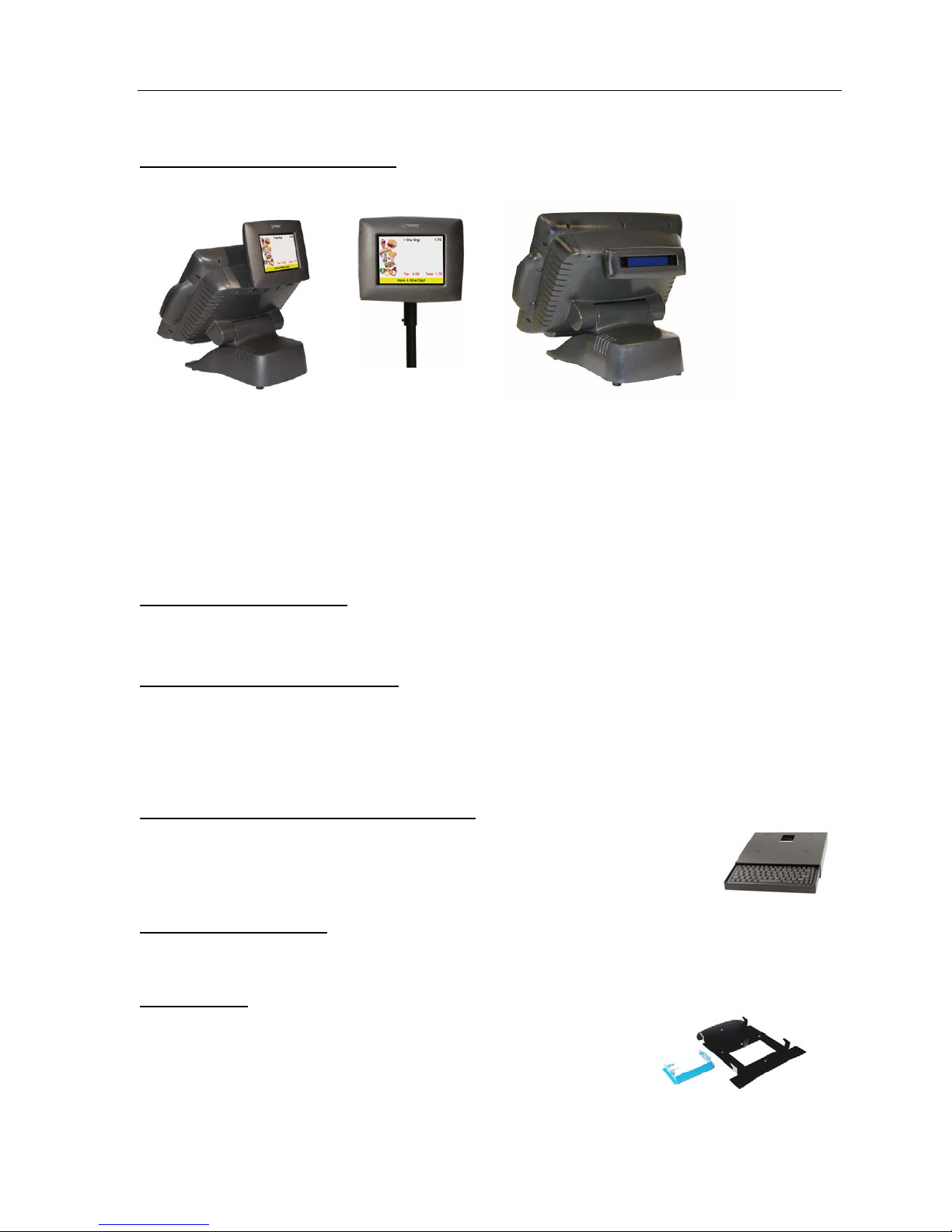
Radiant Customer Display Options
Two features are available depending on the requirement of a 2x20 or Order Confirmation Display.
Radiant offers two options for the customer display including the color 5.5” Digital Video Order Confirmation
Display (OCD) that supports full motion video or the 2x20 VFD Graphical Customer display. Both provide the
ability for customers to view orders as they are entered into the point of sale resulting in increased order
accuracy. Additionally, they can be used as an advertising medium, allowing clients to display specials and
promotions to the customer at the time of purchase. Either display can be tilt stand mounted directly on the
terminal or pole mounted. The Radiant terminal provides the necessary power to operate the OCD or the 2x20
VFD Customer Display. For customer display feature numbers and specifications, see specific General Product
Descriptions for displays.
Advertisement Mounting Kit
Feature Number: P150F020
See configuration options
Kit includes back door and hinges for mounting advertising displays to top, back of terminal.
USB Keyboard with four USB ports
The USB keyboard offers 104 quiet, tactile-feel buttons for excellent user interface. In addition, it has four
downstream USB ports on the rear of the keyboard for connecting additional USB devices. The keycap
symbols are wear-resistant, durable, and easy to clean for demanding users. The keyboar d’s size is 470 x 195 x
38 mm.
USB Mini-Keyboard with Storage Tray (Black)
The USB keyboard and tray is a 86 key, mini-keyboard with a USB interface and a slideout, black metal tray. The keyboard uses quiet, tactile feel technology and has durable,
laser printed, keytop legends. The keyboard is black and the size is 462 x 168 x 41 mm.
DVI to VGA adapter cable
To use a VGA projector or second VGA display, this adaptor cable converts the DVI port on the P1520 to a
VGA port output. DVI Male to DB-15 Male VGA cable.
Wall Mount Kit
This kit includes the wall mount bracket and a tilt prevention bracket which is
mounted to the hinge to position the touch head vertical.
Feature Number: P762F004
Feature Number: CB00429
Feature Number: KB00001
Feature Number: X200F601
Version 1.2 6 04/02/07
Page 9

P1520 User Guide
Typical RJ12 to DB9M adapter kit (should work for pinpads, scanners, etc)
To connect a peripheral device that requires DB9 to a Radiant P15xx POS terminal via serial cable, order the
following the two items below.
1CBDB9RJ DB9M to RJ12 Adaptor
CB10548 6 ft RJ11 cable
Parallel Port Option
This feature adds an internal parallel port to the connectivity panel and provides data I/O with any parallel
peripheral.
Powered USB (24v) Option
This feature adds a 24 volt, powered USB port into the tilt base of the P1520. Powered USB offers a single
connection receptacle that includes both a standard USB connector and a locking power connector
(USB+power). It accepts either a standard USB device or a 24 volt USB device such as a printer. Similar to
the powered serial ports, the powered USB port eliminates the need for a power brick, thereby reducing another
point of potential failure. This option is only available with the tilt base configuration. For more information
on powered USB, see http://www.poweredusb.org/
See configuration options
See configuration optio ns
Specifications
CPU Intel Celeron M (900Mhz or 1.3Ghz) or Pentium M 1.6GHz
Volatile Memory 256MB Std, 2 DIMM slots with up to 2GB DDR SDRAM
Networking Auto-selecting 10Base-T/100Base-T Ethernet using TCP/IP
Primary Display 15” XGA, Active Matrix, dual-bulb, supports auto-stretching
Speaker Integrated 2 watt X 2 speakers for stereo sound
Touch Screen Native support for 5-wire resistive or capacitive
MPEG Video Decoding Software MPEG decoding supported
Enclosure Polycarbonate/ABS impact resistant, high strength blend,
Dimensions (Countertop
envelope through tilt angle)
Base Dimension 11.9” L x 10.7” W
Tilt Angle 20° to 100° from vertical
Weight 22.7 lbs., 10.3 kg
Operating Temperature 32°F – 104°F, 0°C – 40°C
Storage Temperature 32°F – 158°F, 0°C – 70°C
Humidity 5% to 85%, non-condensing
processor (or higher)
supported
VGA and SVGA resolutions
environmentally sealed
13.4 to 14.2” L x 15.8 or 16.8” W x 11.5 to 14.2” H,
34.0 to 36.0 cm L x 40.1 or 42.6 cm W x 29.2 to 36.0 cm H
30.2 cm L x 27.1 W
Environmental Compliance RoHS, WEEE
EMI Certifications FCC Class A, CE, C-Tick
Safety Certifications UL, CUL, CB Scheme
Version 1.2 7 04/02/07
Page 10
P1520 User Guide
2. Installing the P1520
Follow these steps to install a P1520 unit:
1. Place the P1520 with stand in a point of sale area (storefront).
The unit will come completely assembled with tilt stand, touch screen, and customer display (optional)
attached.
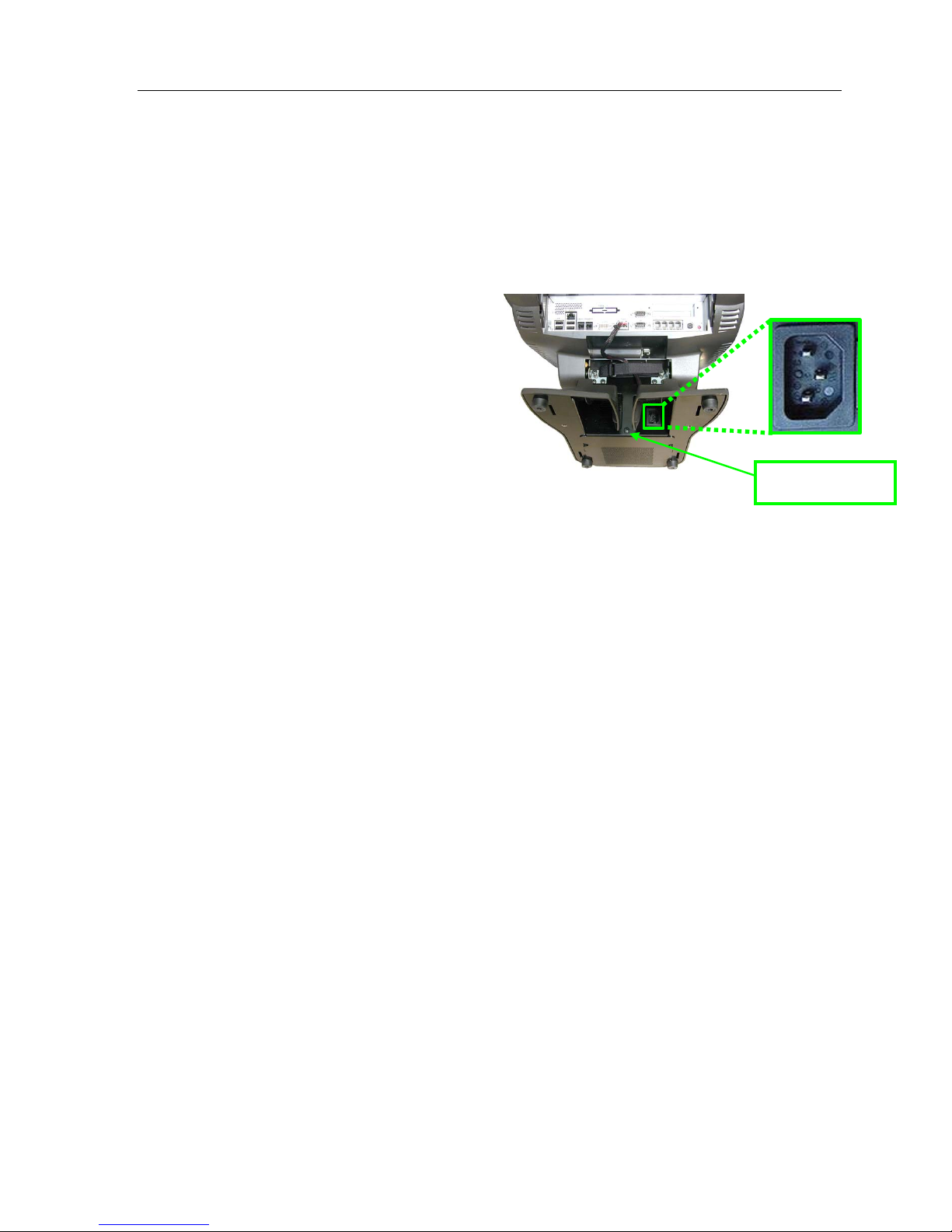
2. The power cord should already be attached to the bottom of the terminal. If not, tilt the terminal to the
side and attach the power cord to the bottom of
the terminal.
3. If available, route power cable through the
power cord hook to prevent accidental
disconnects.
4. Connect the peripheral devices to the
appropriate ports (see connectivity diagram
below)
5. Connect the network cable to the network port.
6. Open the Cable Management System.
7. Route the cables from the terminal connectors
through the Cable Management System and
then down between through the center slot in the plastic base.
8. Connect the power cable to power connector.
¾ Note: The socket-outlet shall be installed near the equipment and shall be easily accessible.
9. The P1520 should boot automatically.
With Radiant Application Software: Upon the initial boot of the P1520, typically the Back Office server
should detect the new P1520 and send all appropriate data files to the unit. After the initial file transfer has
completed, the unit will automatically reboot. Following the reboot the P1520 unit should be fully operational.
Power cord hook
With Third Party Application Software: The P1520 will boot to the operating system or directly to the third
party application.
Cable Restraint: The P1520 includes a cable management system with cable strap to prevent accidental
disconnects and tampering. The strap is opened, peripheral connections are made, the strap is closed, and then
cables are then routed thorough the slot in the base.
Footprint: An area of no less than 16.8” inches square is necessary to properly install a P1520 unit with MSR.
This will accommodate the unit as well as its associated mounting hardware and customer display.
Power: P1520 has an auto-sensing power supply rated for 110V an d 240V, 50Hz or 60Hz located in the base.
Source power is drawn from a regular AC wall outlet. The electronics are “universal” – that is, they will
function when connected to standard wall outlets of most nationalities around the world. For use in locales
other than North America, special wall outlet adapters or cables will be required. For international
configurations of the P1520, typically the country specific power cord is ordered separately.
Moisture: P1520 terminals should not be installed in areas where they might be exposed to direct water spray.
P1520 units are not meant for outdoor installation.
Touch Screen Cleaning: Any standard glass cleaner that is not ammoni a base d or wate r can be used to clean
the touchscreen. Always spray the glass cleaner on the cloth or towel and then clean the touchscreen to prevent
cleaner from running down the glass and gathering on the front bezel.
Version 1.2 8 04/02/07
Page 11
P1520 User Guide
Magnetic Strip Reader (MSR) Cleaning: Periodically, the MSR may need to be cleaned depending on usage.
Pre-saturated MSR cleaning cards can be ordered from Radiant (50/box) using part number ZZ00299 .
Otherwise, wrap a card with a saturated paper towel of glass cleaner and swipe gently to clean reader head.
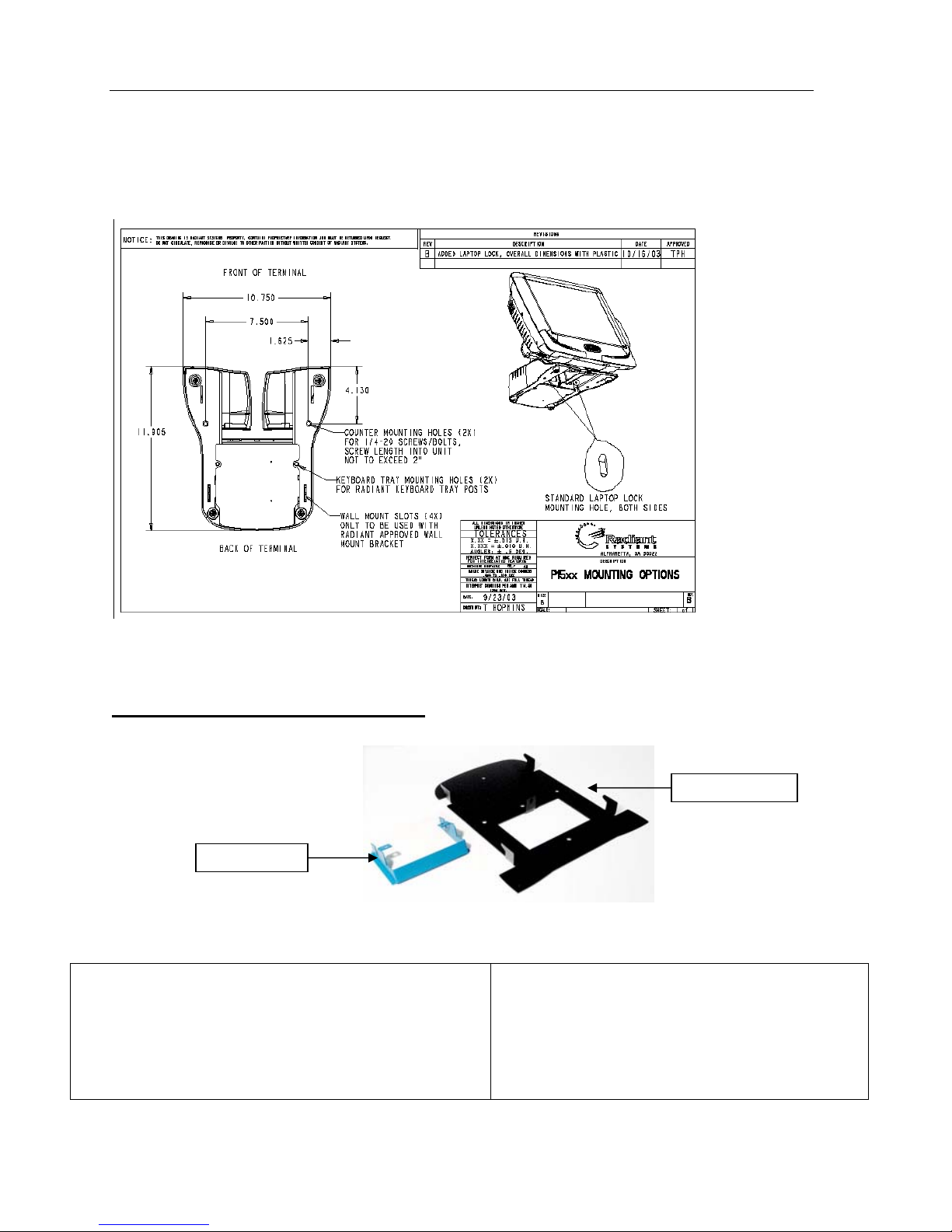
Secure Mounting Dimensions: The P1520 has several mounting options included countertop, wall mount, and
keyboard tray. In addition, we can lock the terminal using a laptop locking cable. See below for bolt pattern.
Wall Mount Installation - P762F004*
1. Tilt Bracket Installation on P15xx
This prevents touch head from rotating down in the wall
mount position. Tilt the P15xx touch head to the back
position for installation of blue tilt mount bracket.
Tilt Bracket
Wall Bracket
2. Remove two machine screw from Cablelock™ or
cable strap as shown.
Note: Blue tilt bracket (MP00648) is installed behind
Cablelock™ on P1550 or behind cable strap on
P1510 or P1520.
Version 1.2 9 04/02/07
Page 12

P1520 User Guide
3. Wall Bracket Installation
Secure wall mounting bracket using 5 ¼-inch screws.
Note: The 3 middle screws must be centered on a
stud when mounting to a sheet rock wall.
5. Place P15xx on wall mount bracket, aligning 4
hang tabs with 4 slots on bottom of P15xx base.
4. Remove single machine screw from P15xx base
located in the cable channel.
6. Secure the P15xx to wall mount by replacing
machine screw removed in Step 4.
For P15xx installed in the US and Canada,
use the hard usage power cord marked
“SJ”
included in the wall mount kit. Do not use the
light-duty cord that was originally provided with
the P15xx when the P15xx is wall mounted.
Version 1.2 10 04/02/07
Page 13

P1520 User Guide
Setting Up the P1520
In order to begin using the P1520 for your POS operations, yo u must f irst set up various standard and peripheral
components, including connecting the power source, connecting the P1520 to your network, and connecting any
necessary peripheral devices. This section outlines these setup processes.
Note: After all connections have been made, always close the Cable Management System to secure
the cables and prevent accidental disconnects. In addition, close the bottom cover after service or installation to
provide protection for the user and prevent contaminants from entering the connectors.
Cable Management System
The Cable Management System is an innovative feature on the P1520 that provides for ease of installation,
controlled access to connectors, concealed cable routing, and cable restraint for better reliability.
Note: After all connections have been made, always close the Cable Management System to secure the cables
and prevent accidental disconnects. In addition, close the bottom cover after service or installation to provide
protection for the user and prevent contaminants from entering the connectors.
1. Tilt touch head back
2. Open Cable Management System strap
3. Plug cables in the input/output connectors
4. Route cables in cable clamp and close clamp
5. Close bottom door and tilt unit to user operating position
Connectivity (I/O) panel
The P1520 offers very high connectivity including 6 RS232, 3 USB, 2 D irect Drive Cash Drawer ports, 2 PS/2
ports, and a parallel port. See Figure 2-1 below for bottom panel details.
Picture 2-1 – P1520 Bottom Panel
Version 1.2 11 04/02/07
Page 14

P1520 User Guide
Parallel
Parallel
(optional)
(optional)
DVI-I Power Serial x 6 LEDs Keyboard On/off
DVI-I Power Serial x 6 LEDs Keyboard On/off
LAN
LAN
10/100
10/100
USB x 4
USB x 4
Cash
Cash
Drawer
Drawer
Terminal Model Number Labels
The P1520 model will be labeled using the Model number (P1520-xxxx) and unique Serial number. The
P1520-xxxx will identify the product configuration. Some configuration feature would include operating
system, storage, RAM, touchscreen, etc. The terminal labels (model number and serial label) are located on the
side of the hinge.
Operating Systems
The P1520 can be configured with different operating systems including XP Professional and XP Embedded.
Connecting the Power Source
P1520 has an auto-sensing power supply rated for 110V and 240V, 50Hz or 60Hz located in the base. Source
power is drawn from a regular AC wall outlet. The electronics are “universal” – that is, they will function when
connected to standard wall outlets of most nationalities around the world. For use in locales other than North
America, special wall outlet adapters or cables will be required. For international configurations of the P1520,
typically the country specific power cord is ordered separately.
Connecting to a Network
Most business configurations will require you to connect your P1520 system to a network. Connecting to a
network will enable you to communicate with other systems and devices also on the network, and depending on
your business' configuration, may allow you to connect to the Internet.
¾ To connect the P1520 to a network, plug the 10/100 Ethernet cable into the port labeled NETWORK on
the bottom panel. The other end of the 10/100 Ethernet cable should be connected into your network hub.
NOTE: You may need to consult with your business' IT (information technology) representative to
determine whether you have a network connection available, and to locate the network hub to
connect to your P1520.
Connecting Peripheral Devices
In order to use the P1520 system to run your business' software, you can set up several peripheral components.
The P1520 is compatible with standard PC equipment, including a USB mouse, USB keyboard, printer,
speakers, network connectivity, as well as any other devices that can be supported by your operating system.
Version 1.2 12 04/02/07
Page 15

P1520 User Guide
This section of the guide covers some of the common peripheral components that you may want to connect to
the P1520.
Using the RS-232 Ports
You can connect various peripheral devices to the P1520 by using any of the six powered RS-232 serial ports
located on the bottom panel. Some peripherals that are commonly supported by the RS-232 ports include
scanners, printers, and cash drawers.
NOTE: Other peripheral devices may also be compatible with the RS-232 serial ports. Please refer to each
device’s User Manual to determine which type of port it supports.
¾ To connect a peripheral device to one of the RS-232 serial ports on the P1520, plug the device cord into
any of the serial ports (labeled RS232 1, 2, 3, 4, 5, and 6 on the bottom panel). See picture 2-1 for a visual
reference of the ports’ location.
¾ The RS232 ports use RJ11 and DB9 connectors (12v, 500 mA). Maximum 18 watts with Radiant.
Pin Name Direction Description
1 CD «— Carrier Detect
2 RXD «— Receive Data
3 TXD —» Transmit Data
4 DTR —» Data Terminal Ready
5 GND System Ground
6 DSR «— Data Set Ready
7 RTS —» Request to Send
8 CTS «— Clear to Send
9 RI «— Ring Indicator
Note: Direction is DTE (C omputer) relative DCE (Modem).
Version 1.2 13 04/02/07
DB9 pin D-SUB male
Page 16

P1520 User Guide
Using the USB Ports
You can connect various peripheral devices to the P1520 by using the four USB (2.0) host ports located on the
bottom panel. Some peripherals that are commonly supported by the USB ports include a keyboard and mouse.
NOTE: Other peripheral devices may also be compatible with the USB serial ports. Please refer to each
device’s User Manual to determine which type of port it supports.
¾ To connect a peripheral device to one of the USB host ports on the P1520, plug the device cord into one of
the USB ports (labeled USB on the bottom panel). See picture 2-1 for a visual reference of the ports ’
location.
Using the Direct Drive Cash Drawer Ports
The P1520 can power two different type cash drawers (direct drive or serial). The terminal has two direct drive
cash drawer ports with RJ11 (4 pin) connectors labeled, 1 and 2, on the bottom I/O panel. The cash drawer
itself typically has a solenoid for firing the drawer and a switch for determining whether the drawer is open or
closed. For serial cash drawers, connection is made to one of the powered serial powers available on the P1520.
Pinout for DDCD ports
Orientation: looking into the connector with tab on BOTTOM, then pin 1 is on the right side
Pin 1 sense
Pin 2 Fire
Pin 3 GND
Pin 4 GND
Connectivity TOP panel
The P1520 offers secure, but easy access to the top panel for additional connectivity. See Figure 2-2 below for
top panel details.
Picture 2-2 – P1520 Top Panel
With Cables connected
Backlight
CompactFlash
port
Hard
Drive
Power
Hard Drive
Data
LCD
Touch
screen
(Resistive)
Version 1.2 14 04/02/07
Page 17

P1520 User Guide
Using the PCI Expansion Slot
The P1520 motherboard has a general purpose PCI (3.3V) expansion slot to connect various expansion cards. It
uses a low-profile riser (3.3V) in combination with a low-profile PCI card (3.3V or Universal card). For more
information, contact Radiant or reference
¾ Typically, Radiant will install the riser and specific PCI card at manufacturing since it is connected directly
to the motherboard. It is not recommended to install a card in the field.
http://www.pcisig.org.
Full Size PCI vs Low Profile PCI 2.2
Storage
The P1520 can be configured with USB Disk on Chip (uDOC), Compact Flash, or 3.5” Hard Disk Drive
storage.
Hard Drive Storage
NOTE: Unplug the terminal before opening the back panel door.
You can access the hard drive on the P1520 located on the top panel. See picture 2-2 for a visual
reference of the slots’ location.
Compact Flash Storage
NOTE: Unplug the terminal before opening the back panel door.
You can access the compact flash slot located on the top panel. See picture 2-2 for a visual reference
of the slots’ location. The compact flash slot will only support storage media cards since it is an IDE
interface.
uDOC Storage
A qualified technician is needed to access the uDOC on the P1520 as it is an internal component on the
motherboard and requires disassembly of the front bezel.
Version 1.2 15 04/02/07
Page 18

P1520 User Guide
LED Diagnostics
On the bottom panel of the P1520, there are 2 LED lights on the network port and 3 on the connectivity panel
that can be used for diagnostics.
Network LEDs
¾ Green - "Lnk" - is active and solid with functioning network connection.
¾ Yellow - "Act" - is active if activity (transmit and receive) data is on the
network
Connectivity Panel LEDs
¾ Green -“PWR” - is active and solid with power to the motherboard/terminal.
¾ Red -“HDD” - is active if activity is occurring with the hard disk drive
¾ Yellow/Green -“STAT” - functionality as follows:
STAT Codes STAT LED color
In S5 state: Off
Early in BIOS: Constant yellow
BIOS transition to Operating System (OS) load: Alternating yellow and green
Operating System load complete: Green flashing heartbeat
STAT Error Codes STAT LED color
BIOS post errors: Flashing yellow
OS boot failure: Flashing yellow
10/100 LAN
(2 LEDs)
3. Using the P1520
The P1520 platform functions as a POS terminal for your business. Performance and functionality will differ
according to the operating system, software, and peripheral devices you install.
Starting Up the P1520
In order to run your operating system and access your software and data, you must star t up the P1520 platform.
To start up the P1520, complete the following step:
¾ Simply plug the power cord into an electrical outlet. The system automatically turns on once plugged into
the outlet.
NOTE: Depending on your installed operating system and your selected settings, your system will vary in
the amount of time it takes to boot up.
Shutting Down the P1520
It is highly recommended to properly shut down the P1520 to avoid operating system corruption due to hard
power loss. To shut down the P1520, complete the following steps:
1. If using a software application, typically there is a software shutdown button in the manager’s setup screen
which should be used to properly shut down the terminal. If a shutdown button does not exist, then exist
Version 1.2 16 04/02/07
Page 19

P1520 User Guide
the application to the operating system and shut down gracefully through the operating system (see #2
below)
2. Properly shut down your operating system. For Windows operating systems (XP-Embedded and XP-
Professional), you can do this by selecting Shut Down from the Start menu.
NOTE: The above steps may vary depending on your installed operating system and software application.
3. If proper shutdown through the software application or operating system is not achievable. Then, press the
“On/Off” button located on the I/O connectivity panel at the bottom P1520. This will create an operating
system shutdown.
4. If none of the options above are responding or simple not available, then unplug the terminal from the
outlet. Note: This should be avoided at all times to avoided operating system corruption due to hard power
loss.
Optional Mylar Overlay on the P1520 Resistive Touchscreens
Resistive touch screens wear over time, as do other input devices such as keypads and keyboards. To preserve
the touch screen, Radiant offers a thin, mylar overlay affixed over the touch screen for protection. This overlay
is similar to those used on Personal Digital Assistants (PDA) found in the consumer market for touch screen
protection. The overlay is easily field replaceable and provides an effective way to extend the touch screen life.
The part number is P770F001 for a pack of 4 replacement overlays when the overlay becomes worn or needs
replacement.
Benefits
• Protects touch screen from wear and prolongs touch screen life
• Protects touch screen from indentions of sharp objects such as pens
• Reduces terminal returns and increases uptime at site
• Field replaceable when touch screen shows cosmetic degradation
• Installation instructions printed on each overlay
Installation Instructions
Below are the installation instructions which are printed on the label attached to each replacement overlay.
Version 1.2 17 04/02/07
Page 20

P1520 User Guide
Touch Calibration
The P1520 with resistive or capacitive touch screen will already be calibrated before it ships from Radiant
Manufacturing. It should not require a recalibration through the life of the terminal. However, if touch issues
arise, it is recommended that re-calibration be tried first before returning the terminal.
A way to determine if you have resistive or capacitive touch screen is to gently touch the screen with an object
different from a finger. This could be a plastic part of a pen, cardboard, etc. Resistive screens will accept all
input devices including finger or styluses whereas capacitive will just accept finger and/or conductive input
devices. If the plastic part of the pen does not register a touch, the terminal is likely to have a capacitive touch
screen which requires finger input for best results.
Resistive touch screen
For resistive touch screen, Radiant uses 4 point calibration to achieve the best accuracy. The below steps
outline how to re-calibrate the touch screen. Note: Do not use any sharp objects, pens, pencils, or any material
expect a finger to contact touch screen sense it could damage the touch sensing layer.
With a Radiant application, from the managers menu, select calibrate touchscreen.
From the desktop or startup menuÆrunÆtype: tcalib
You can also run the tcalib from the P15xx folder.
See picture below.
\
Additional Touch settings for Resistive
Below are some variables that can be adjusted in the control panel in the P15xx Hardware to help with touch
parameters such as internet browser buttons.
Touch double-click speed settings
Go to Hkey_current_user
The number is the time (in milliseconds) in between clicks to register as a double-click. If it's set
extremely low, you can eliminate double-clicking altogether. For example, at the default value of 500
DoubleClickSpeed you have 1/2 a second to click twice. At 100 DoubleClickSpeed you have 1/10 of a
second, and at 1500 DoubleClickSpeed you have 1 1/2 seconds. The clicks must happen inside the
height and width restrictions, which are in pixels.
Touch drag settings
This changes the size of the area Windows uses to differentiate between a click and a drag. The user
can change the DragWidth and DragHeight to 30 pixels from the default value of 4. This prevents the
'Forbidden' symbol
Capacitive touch screen
Version 1.2 18 04/02/07
Æ
control panelÆmouseÆdoubleclickspeed
; from appearing when you try to click buttons that are made with pictures.
Page 21

P1520 User Guide
For Capacitive touch screen, Radiant uses calibration to achieve the best accuracy. To re-calibrate, go to
desktop or programsÆ TouchwareÆCalibrate. In addition to calibration, you can adjust touch settings,
curser, etc. from the Touchware interface (see picture below). The capacitive touch screen does not connect to
the touch screen port on the top of the terminal.
Note: The P1520 will already be calibrated before it ships from Radiant Manufacturing. It should not require a
recalibration.
Touch Screen Cleaning
Any standard glass cleaner or water can be used to clean the resistive or capacitive touchscreen. Always spray
the glass cleaner on the cloth or towel and then clean the touchscreen.
4. Upgrading/Replacing Components
Warning! - Upgrading and replacing parts will be done by trained Service
Personnel only!
Below are the instruction for upgrading and replacing the MSR, Hard Drive, Compact Flash, and power
supplies. “For doors or covers intended to be removed by operator for installation of accessory devices,
instructions shall be provided for the correct removal and reinstallation of the door.”
Replacing a MSR
The below section describes how to upgrade or replace an MSR.
1. Power down unit via software or On/Off button
2. Important: UNPLUG power cord from wall or terminal
3. Unscrew two phillips screws securing the MSR plastic to the touch head (as shown below)
4. Gently disconnect the MSR assembly from the touch head and disconnect MSR connector from
touch head connector. Note that the cable has only 2 inches of slack, so be careful to not pull MSR
too far.
Version 1.2 19 04/02/07
Page 22

P1520 User Guide
5. Obtain new MSR assembly and reverse steps.
Replacing a Hard Drive or Compact Flash
The below section describes how to upgrade or replace a hard drive or compact flash.
1. Power down unit via software or On/Of f but t o n
2. Important: UNPLUG power cord from wall or terminal
3. Remove the back panel cover (2 phillips screws).
4. Disconnect hard drive power and hard drive data connectors (see figure 2-2 for reference and
picture below). For compact flash, remove card and insert new card in compact flash slot.
5. Unscrew 2 phillips screws holding hard drive mounting brackets to metal can
Two phillips screws
to open top panel
Version 1.2 20 04/02/07
Page 23

P1520 User Guide
6. Remove the hard drive and replace with new hard drive.
7. Screw the 2 phillips screws, which secure the hard drive, into the can.
8. Reconnect the hard drive power and hard drive data connections.
9. Replace back panel and secure with 2 phillips screws
Replacing a Customer Display
The below section describes how to upgrade or replace a customer display.
1. Power down unit via software or On/Off button
2. Important: UNPLUG power cord from wall or terminal
3. Disconnect customer display cable from terminal connection at bottom of terminal (see Figure 2-1)
4. Unscrew 2 phillips screws from top cover while holding the customer display so that it doesn’t fall
5. Gently pull customer display module and top door assembly from the terminal
6. Disconnect the cable from customer display module and attach to replacement display module. If a
new cable is included with replacement module, use the new cable.
7. Route the cable through the plastic cable restraints on the back of each display and through the top
door.
8. Re-attach the customer display and top door module to terminal.
9. Screw the 2 phillips screws into the top cover to secure it.
Version 1.2 21 04/02/07
Top cover.
2 screws to
remove.
Cable routing
for DV OCD
display
Cable
routing for
2x20 display
Page 24

P1520 User Guide
Replacing a Power Supply
The below section describes how to upgrade or replace a power supply module. The replacement power supply
module will contain both power supplies and the mounting brac ket. The P1520 uses one fan cooled power
supply.
1. Power down unit via software or On/Off button
2. Important: UNPLUG power cord from wall or terminal
3. Turn terminal on side or face down (make sure the countertop is clear of objects to avoid touch screen
damage). Remove screw holding the power supply to the base. (see below)
4. Gently slide the power supply module out of the base and set off to the side of the unit.
5. Disconnect the power supply module (supply + metal bracket) at the connector located next to the
power supply. Below is shown the entire power supply and cable assembly.
Version 1.2 22 04/02/07
Page 25

P1520 User Guide
6. Obtain new power supply module and reverse steps listed above.
7. Gently reinsert power supply module and slide forward
8. Attach holding screw.
Important Safety Warning For Coin Battery Replacement and Handling
CAUTION: Risk of Explosion if Battery is replaced by an Incorrect Type. Dispose of Used Batteries
According to the instructions.
5. P1520 Device Drivers
Below is a list of drivers on the P1520. To view the P15xx Configurations and Settings interface, go
StartÆControl PanelÆP15xx Hardware. Also, please see instruction file located at in c:/P15xx/ directory on
Windows XP and Windows XP Embedded images for more information or contact Radiant Systems.
Shortcut located in the control panel
General P15xx Configuration and Settings
• General
o Control backlight to primary displa y or seco ndary Radiant Digital Video Displa y
• Odometers
• OPOS
• MSR settings
o Start or stop MSR Keyboard Wedge Service
Version 1.2 23 04/02/07
Page 26

o Enable 3 Track MSR
Primary BacklightPrimary Backlight
Platform ModelPlatform Model
Unit Serial Number
Unit Serial Number
BIOS VersionBIOS Version
P1520 User Guide
P15xx Driver VersionP15xx Driver Version
Calibrate Resistive
Calibrate Resistive
Touch Screen
Touch Screen
System CountersSystem Counters
Thermal CountersThermal Counters
Screen & Touch
Screen & Touch
(Resistive Only)
(Resistive Only)
Counters
Counters
Cash Drawer
Cash Drawer
Counters
Counters
MSR CountersMSR Counters
Version 1.2 24 04/02/07
Page 27

P1520 User Guide
Note: MSR Keyboard
Wedge Service needs to
be stopped for OPOS test.
MSR Keyboard
MSR Keyboard
Wedge service Status
Wedge service Status
Start/Stop MSR
Stopped: OPOS
Stopped: OPOS
Started: Keyboard
Started: Keyboard
(Test with Notepad)
(Test with Notepad)
Enable MSR
Enable MSR
Keyboard Wedge
Keyboard Wedge
service to start at
service to start at
boot time
boot time
Start/Stop MSR
Keyboard Wedge
Keyboard Wedge
service manually
service manually
The OPOS configuration naming can be looked up in the registry under:
HKEY_LOCAL_MACHINE\SOFTWARE\OLEforRetail\ServiceOPOS
P15xx (dvOCD/C500) P704Fxxx Software Developers Kit (SDK) - Revision 2
Overview
Version 1.2 25 04/02/07
Page 28

P1520 User Guide
The Radiant dvOCD plugs into the secondary video port on the P1550 via the DVI-I connector. The P1550 has
plug and play logic to detect the screen and adjust video parameters when it is attached or detached. When
attached, the windows desktop and the screen in general are extended onto the dvOCD. As shown below, the
dvOCD is virtually to the right of the main screen with an upper left corner at x=1024,y=0 and a size of
320x240.
The Intel video driver will recognize the dvOCD as a 640x480 display. There is currently no fix for this. So
maximizing a window on the dvOCD is not recommended as you will only see a quarter of it. Applications will
need to specifically create their window in and draw only to the 320x240 visible area of this
screen.
Main Screen dvOCD
Application Programming
Applications can draw to the dvOCD by drawing to its area of the virtual screen. For example, an application
could draw a 50x50 bitmap to x=1124,y=100.
Applications written on top of Radiant's RadIoApi, a Radiant Systems specific application, can also easily write
to the dvOCD. Each Radio video call has a screen number (or device number) parameter. This parameter
should be set to 0 for the main screen and to 1 for the dvOCD.
It is possible during runtime to determine if the dvOCD screen is plugged in and recognized by querying
Windows for the screen size. The Win32 function for doing this is prototyped below along with 4 pertinent
values for nIndex. Querying for SM_CXSCREEN and SM_CYSCREEN will return the size of the Main
screen. Querying SM_CXVIRTUALSCREEN and SM_CYVIRTUALSCREEN will return the entire size of all
the combined screens. So if GetSystemMetrics reports the virtual screen is larger than the screen, there is a
dvOCD attached and configured. Otherwise, there is not.
int GetSystemMetrics( int nIndex );
nIndex values: SM_CXSCREEN, SM_CYSCREEN, SM_CXVIRTUALSCREEN,
SM_CYVIRTUALSCREEN
Sample Applications
Radiant provides two sample programs for displaying content on the dvOCD. The first, BBDemo.exe, will play
a motion video file, positioning and resizing it to fill up the dvOCD. It accepts most motion video file formats.
The second, BBSlides.exe, will play a slideshow on the dvOCD. It takes a folder of image files and loops
through them, resizing each to fit on the dvOCD and displaying each for a configurable number of seconds.
Both apps are part of the driver package and should be in the C:\P15xx folder. BBSlides is a recent addition
and may not be on all P1550s.
USAGE:
BBDemo.exe video_file
Example:
Version 1.2 26 04/02/07
Page 29

P1520 User Guide
BBDemo.exe C:\advertisment.mpg
USAGE:
BBSlides.exe p=Path_to_Folder t=time
Example:
BBSlides.exe p=C:\Slides t=5
Upgrading BIOS using RadFlash.exe
Using RadFlash.exe to upgrade BIOS
RadFlash.exe is located in the C:\P15xx folder
BIOS ROM Files
• Located in C:\P15xx folder unless they were released after the P15xx Platform
Driver release
• They can also be found at the Radiant Hardware Driver Downloads website
Run RadFlash.exe from the command line
• P1510 BIOS Example:
RadFlash P1510_BIOS_0025.ROM
• Reboot after flashing BIOS
6. Removing a Defective P1520
Follow these steps to replace a P1520:
1. Locate the unit to be serviced.
2. Properly shut down the terminal through either the software application, operating system, or by
using the “On/Off” button on the bottom panel.
3. Locate the AC power connection at the wall outlet.
4. Disconnect the power cable from the wall outlet
5. Tilt the terminal back and open the access door to the connectivity panel on the bottom of the
touch head.
6. Disconnect the network cable from the network port.
7. Note which RJ11 port number each peripheral device is connected to.
This information will be used later to re-connect the peripheral device cables.
8. Disconnect all peripheral device cables from the RJ11 and/or USB ports.
9. Open the Cable Management™ System by pressing the blue tab in the arrow direction.
Version 1.2 27 04/02/07
Page 30

P1520 User Guide
10. Route the cables from the terminal connectors out of the Cable Management™ System and then
down between through the center slot in the plastic base. Close the Cable Management™ System
clamp.
11. Close the bottom access door and tilt the terminal upright.
12. Place the defective P1520 into the original shipment packaging and return to the appropriate repair
center.
7. Hardware Certifications
The certification label is located on the P1520 plastic bottom panel.
Federal Communications Commission Compliance Statement
This equipment has been tested and found to comply with the limits for a Class A digital device, pursuant to
Part 15 of the FCC Rules. These limits are designed to provide reasonable protection against harmful
interference when the equipment is operated in a commercial environment. This equipment generates, uses, and
can radiate radio frequency energy and, if not installed and use in accordance with the instruction manual, may
cause harmful interference to radio communications. Operation of this equipment in a residential area is likely
to cause harmful interference in which case the user will be required to correct the interference at his own
expense.
Changes or modifications to this unit not expressly approved by the party responsible for compliance could void
the user’s authority to operate the equipment.
Canadian Compliance Statement
"This Class A digital apparatus complies with Canadian ICES-003."
"Cet appareil numérique de la classe A est conforme à la norme
NMB-003 Canada."
European Union Compliance Statement
This Information Technology Equipment has been tested and found to comply with the following European
directives:
EMC Directive 89/336/EEC using EN55022 and EN55024
Safety Compliance Statement
This Information Technology Equipment has been tested to the UL 60950 (1999) Third Edition safety standard
as developed by Underwriters Laboratories (UL).
Sample of Certifications Label as of 12/12/06
Version 1.2 28 04/02/07
Page 31

P1520 User Guide
Version 1.2 29 04/02/07
Page 32

P1520 User Guide
8. Appendix: P1520 Troubleshooting Guide
This document provides a checklist of troubleshooting steps to review before replacing a P1520 POS.
Hardware Troubleshooting:
Is the P1520 calibrated correctly?
Re-calibrate through the application managers menu or through the operating system. At command
prompt type tcalib for RESISITIVE touchsreens. See below for capacitive touchscreen
troubleshooting.
Is the touch screen going blank when idle?
This is a critical feature of the P1520. After a period of time (30 minutes or more), the screen will go
blank in a screen saver mode. This helps prolong the bulb life of the LCD. If you touch the screen or
press any key on the keyboard, it should wake up. Do not replace the touchscreen until this has been
checked.
Is there no image after touching the screen?
a. Check the underside of the touch head. There are network lights that should be on:
Green - "Lnk" - is active and solid with functioning network connection.
Yellow - "Act" - is active if activity (transmit and receive) data is on the network
b. Check to make sure the unit is plugged in at BOTH the wall and at the bottom of the terminal.
Also, check the power connection from the base to the touch head located at the I/O panel at
the bottom of the touch head.
c. If there is still no power, trace the power cable from the terminal to the source (usually a
power strip or a battery backup) and verify power there.
d. If power is good at the source but still not at the touch head, try swapping out the power cable
from another POS. If another power cable provides power, then the cable is the bad part. You
will have to replace the power cable.
e. If the screen does not come on, check all connections. Reboot the POS. If the screen does
not work at this point, you may have to replace the unit.
f. If all the above did not work, it is most likely a hardware problem with the touch head or
power supply, and the power supply or entire terminal should be replaced.
Is the Hard Disk Malfunctioning?
If there is a message on the screen indicating hard disk failure, try powering down unit using on/off
button and rebooting. If no response, pull the power cord. If unit doesn’t boot and says hard disk
failure or Unmountable Boot Volume error, you will probably have to replace the unit.
Is the MSR malfunctioning?
a. You will need to determine if the application is causing the issue or if it appears to be
hardware problem. To determine if it is hardware, go to C:/P1520/. Search for
MSRWIN.exe. Run this program which will bring up a new window.
b. Try swiping a known good card and it should display text. MSR cards can have 1, 2, or 3
tracks of data. If it is reading all errors, “EEE” will be displayed. Try a different card to
make sure a bad card is being swiped.
c. If it continues to display EEE or does not display any information, reboot the terminal via
software or the On/Off button.
Version 1.2 30 04/02/07
Page 33

P1520 User Guide
d. If that does not resolve the issue, replace the MSR or terminal.
e. If MSR is just intermittent, try cleaning the MSR by using a card wrapping in a cleaning cloth
with cleaning solution (ie. paper towel sprayed and then wrapped around a card)
Warning!
The OS on the P1520 is typically Windows XP. There is a known issue with Windows XP when
cold/hard booting which can make the P1520 inoperable and requ ire replacement du e to operating system
corruption. Use the On/Off button on the P1520 BEFORE unplugging the terminal. Only power down or
unplug the P1520 as a last resort.
Are the serial ports working?
Using Hyperterminal to test COM ports on Radiant Systems POS systems. Basic instructions:
1) Cabling: For Radiant Systems RJ-type ports, you can communicate between ports using any of the
standard RJ cables that ship with our products. These cables have a ‘half-twist’ so that all outbound signals will
automatically be routed to the appropriate inputs on the other side. (RJ ports are the ones using the standard
telecom modular plugs with the locking tabs).
For standard DB-9 ports, a null modem cable must be used. This is a cable that swaps all of the signal pairs
and has a female DB-9 connector on each end. Alternately, if you have a DB-9 to RJ adapter such as CN00322
you can connect a DB-9 port to an RJ-type port or two DB-9 ports together. See RJ_End diagram for details on
pinouts.
Connect two serial ports together
a. For RJ12 ports use a twisted RJ12 cable
b. For DB9 use NULL Modem cable
RJ_End Diagram
2) Launch HyperTerminal
a. Either launch from Start > Programs > Accessories > Communications >
HyperTerminal or C:\Program Files\Windows NT\hypertrm.exe
b. Configure HyperTerminal with the COM port to test and set the Baud to 115200.
c. Launch two copies of HyperTerminal to communicate between the ports
3) The program will have several prompts, some will only appear the first time you run the program:
Version 1.2 31 04/02/07
Page 34

P1520 User Guide
c. Make hyperterminal the default telnet program.
d. Specify any area code you wish – the program insists on having this information.
e. Just hit OK on prompt to select a location…use ‘My Location.’
f. If prompted to install a modem, click ‘No.’
g. Enter a connection name – ‘COM’ is restrict ed but ‘Comm1’ ‘Comm2’ etc are not.
h. Set equal bits per second, etc. Make sure you use the same ‘Flow Control’ on each – ‘None’
might be the best choice.
COM 1
This is a COM3 test
!@#$%^&*()_+
Type here – Should show
up on other COM port
This is a COM1 test
!@#$%^&*()_+
Type here – Should show
up on other COM port
COM 3
Capacitive Touch Screen Troubleshooting
Purpose
This outlines basic troubleshooting steps for Radiant Systems Point-of-Sale equipment using 3M Capacitive
touch screens and controllers. The driver package selected in this document covers all possible combinations
of deployed 3M Touch Controllers and Touch Glass.
The driver package covered in this document is the following:
3M Version 5.64SR4 with RUNME.bat script (5.64_SR4.zip)
Radiant custom un-install/install script RUNME.bat version 1.3
3M USBrestore.exe version 1.0
Rads3MFixOrientation.exe version 1.0
Driver Location on Point-of-Sale
C:\Drivers\3M 5.64_SR4
C:\Drivers\3M Touch\3M 5.64_SR4
Download Location
http://www.radiantsystems.com/downloads/drivers/all/5.64_SR4.zip
http://www.radiantsystems.com/hardware/drivers.asp
Recommendations
Radiant Systems recommends downloading 5.64_SR4.zip and running RUNME.bat v.1.3 for remedy the
following symptoms:
“Shaky” or “Ghostly” touch
Inverted touch
Drifting touch
Troubleshooting
Symptom:
Resolution:
Inverted Touch, Inaccurate Touch
Try calibrating the touch screen
Version 1.2 32 04/02/07
Page 35

P1520 User Guide
Go to Start > (All) Programs > TouchWare > Calibrate tab > Calibrate button
Command line: C:\PROGRA~1\MICROT~1\TOUCHW~1\MTSCAL.exe /C
Symptom:
Calibrate button not working in Aloha POS application
Resolution: Change the calibration path to reference the driver being used (RKBID#59 5 9)
Set the calibration variable for driver 5.64_SR4
CALIBRATE=C:\PROGRA~1\MICROT~1\TOUCHW~1\MTSCAL.exe /C
Symptom:
When using C500 or C1200 Radiant customer displays as a secondary monitor, the calibration
screen stretches onto the C500 or C1200 monitor.
Resolution:
The TouchWare Monitor program is not running. This program upd a tes the registry with the
current coordinates of the primary display to calibrate.
Check to see if the TouchWare Monitor shortcut was removed from the Startup folder. If missing
recreate the shortcut to MtsTsMon.exe
C:\PROGRA~1\MICROT~1\TOUCHW~1\MtsTsMon.exe
Symptom:
Calibration did not fix accuracy, or touch is inaccurate on certain parts of the glass.
Resolution: Linearization of the touch glass needs to be performed.
CAUTION: This is an advanced procedure and should only be performed by a qualified technician.
Enable Linearization in the TouchWare Properties
Go to Start > (All) Programs > TouchWare > Tools tab
Select Options… button
Select Advanced… button
Add checkmark ; Enable Linearization
Select Close button on the last two windows to get back to the Tools screen
Perform 25-Point Linearization
Select Linearize button, and select Yes button to continue
After Linearization, proceed to the Calibrate tab a to run 2-point calibration
Version 1.2 33 04/02/07
 Loading...