

Page 1
True to the Music
Radial Engineering Ltd.
1588 Kebet Way, Port Coquitlam BC V3C 5M5
tel: 604-942-1001 • fax: 604-942-1010
www.radialeng.com
email: info@radialeng.com • web: www.radialeng.com
Specifi cations and appearance are subject to change without notice.
Copyright © 2015 Radial Engineering Ltd.
www.radialeng.com
Page 2

THIS PAGE INTENTIONALY LEFT BLANK
Page 3
True to the Music
Radial Space Heater
Table of Contents .....................................................................................................Page
Front Panel Feature Set Overview ......................................................................................................................1
Rear Panel Feature Set Overview .......................................................................................................................2
Introduction To The Space Heater .......................................................................................................................3
Understanding The Signal Flow ..........................................................................................................................4
Features And Controls .........................................................................................................................................5
Connectivity .........................................................................................................................................................6
Master Section.....................................................................................................................................................7
Using As A Summing Mixer .................................................................................................................................8
Space Heater Applications ............................................................................................................................ 9-10
Changing the Tubes .......................................................................................................................................... 11
Specifi cations and Connectors ..........................................................................................................................12
Radial Limited Warranty ..................................................................................................................... Back Cover
Congratulations on your purchase of the Radial Space Heater™ Summing Mixer and Tube Overdrive. The Space
Heater is a studio-grade tube distortion unit and detailed analog mixer with personality. This manual covers the
setup and operation of the Space Heater in both the studio and live sound. Please take a few minutes to read
through this manual in order to familiarize yourself with the Space Heater’s features and applications. Inside you
will fi nd important safety features along with tips on how to get the most out of your Space Heater.
Should you have any questions on an application not covered in this manual, we invite you to log onto the Radial
Engineering website at radialeng.com to check the Space Heater’s FAQ section for the latest updates. If you still
do not fi nd what you are looking for, feel free to send us an email at info@radialeng.com.
Now lets get started warming things up… or let your destructive side shine!
!
Note: The Radial Space Heater is solely intended for use by audio professionals. These professionals
are expected to be familiar with safety issues regarding electrical systems and sound pressure levels that
could cause ear damage after extended exposure. If you are not familiar with these, please contact your
local electrical and health authorities as Radial has no means to ensure products like the Space Heater
are being used according to local rules and regulations.
IMPORTANT SAFETY & USER NOTICE - FOR PROFESSIONAL USE ONLY
Radial Engineering Ltd. Space Heater™ User Guide
Page 4
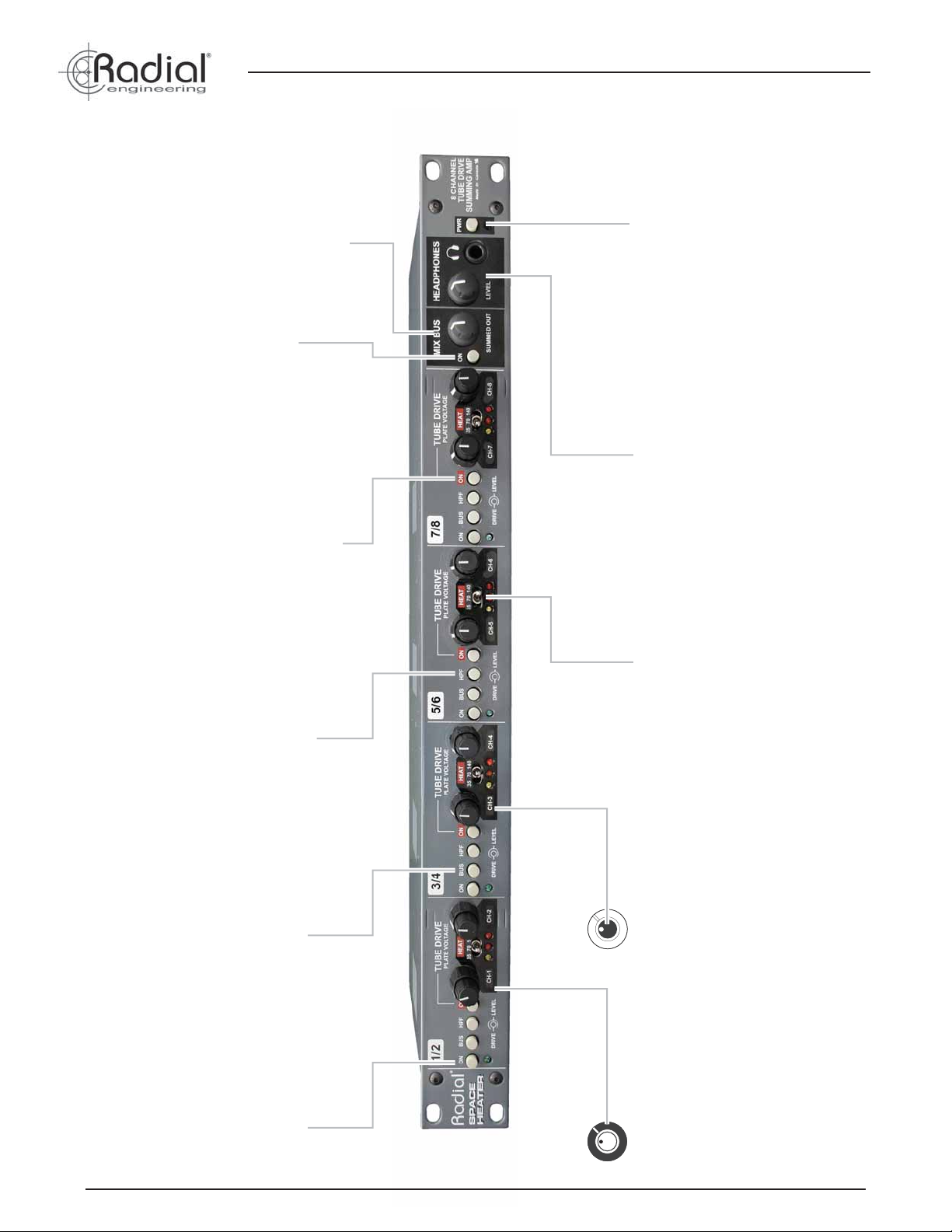
MIX BUS LEVEL CONTROL:
Used to adjust the summing
mixer output.
MIX BUS ON: Turns
on the stereeo XLR-M
outputs.
True to the Music
POWER SWITCH: Turn off to
conserve tube life and reduce
power consumption and heat.
HEADPHONE LEVEL: Built
with standard ¼” stereo output.
TUBE DRIVE ON: Routes the
audio signal to the tube drive -
may be bypassed to compare
wet versus dry.
HPF: High-pass fi lter gently
rolls off low frequency
resonance below 40Hz across
both channels on the pair.
BUS: Sends the channel
set to the stereo mix bus
and headphones.
HEAT: Three position switch
changes the tube voltage for
each pair with 35,70 or 140 Volt
settings for different levels of
distortion.
LEVEL: Inner control on each
concentric pot sets the output
from the tube drive - acts like a
master volume on a tube guitar
amp.
FRONT PANEL FEATURE SET
Radial Engineering Ltd.
ON: Used to turn on (or
bypass) each of the four
channel sets.
DRIVE: Outer control on
each concentric pot sets the
level going to the tube drive
circuit.
1
Space Heater™ User Guide
Page 5
True to the Music
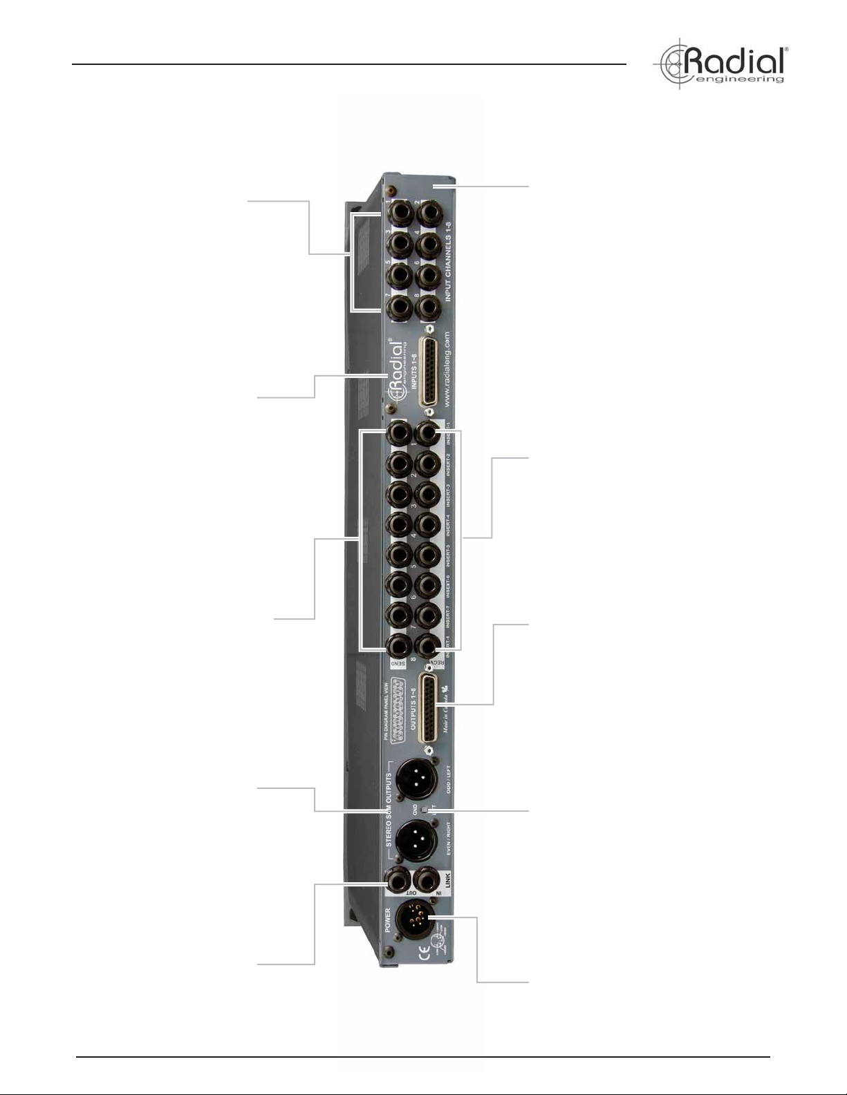
INPUT (1-8): Eight ¼” TRS
balanced inputs for easy
connection to the Space Heater.
14-GUAGE STEEL: Heavy duty
construction eliminates stress on
the PCB and provides excellent
shielding against magnetic fi elds.
D-SUB INPUT (1-8): DB25
connector follows the Tascam/
Protools standard and is wired in
parallel to the ¼” input jacks.
SEND (1-8): Eight ¼” TRS
balanced sends feed the post tube
signal to an external processor or
may be used as additional outputs
for parallel processing.
STEREO SUM OUTPUTS:
Provide left and right summed
outputs for the most luxurious
old school analogue character.
RECV: Eight ¼” TRS balanced
receive jacks bring the signal
back to the Space Heater and
routes it to the D-Sub output or
stereo mix bus.
D-SUB OUTPUT (1-8): DB25
connector used to send all eight
+4dBu transformer isolated
channels back to the mixing
console or workstation.
GROUND LIFT: Recessed
switch lifts pin-1 on the two
XLR outputs to help reduce
hum and buzz caused by
ground loops.
REAR PANEL FEATURE SET
Radial Engineering Ltd. Space Heater™ User Guide
LINK: Stereo ¼” TRS link used
to combine two or more Space
Heaters together for 16x2, 24x2
or 32x2 tube summing.
POWER: 5-pin locking XLR
connection for external
power supply.
2
Page 6

INTRODUCTION
The Space Heater is a combination 8x2 summing mixer and a badass 8-channel harmonic distortion device that lets you add a little,
more, or a lot of distortion to your signal path. In some situations
you may fi nd that adding just a bit of bite to a vocal track can bring
out subtleties without adding a compressor or increasing level. On
acoustic guitar, the natural compression of a distorted tube circuit
can enhance harmonics that may otherwise be lost. On bass, a
medium distortion will bring back the vintage tone and feel as if
connected to an old SVT or Marshall bass amp. And with drums,
you can add crunch to expand the size of the drums without overprocessing.
Because the Space Heater can be used in a number of ways, it
is important to understand its architecture and signal fl ow. It is
equipped with four 12AX7 tube drive circuits wired in stereo. While
you do have separate DRIVE and LEVEL controls on each channel,
certain functions are shared across both sides of the tube. Lets get
started...
POWER
The Space Heater employs a universal power supply that accepts all
voltages from 100V to 240V. This in-line power supply is equipped
with a standard IEC/EIN power input so that you only need to
change the cable to suit the local power connector types. A locking
5-pin XLR connects the external power supply to the Space Heater.
True to the Music
Channel 1 Channel 1
Channel 2
EXTERNAL POWER SUPPLY
Channel 2
At the far right hand side of the front panel is a power switch. We
recommend that you keep the Space Heater turned off when not in
use to prolong tube life and save power. Turn the Space Heater on
at least 15 minutes before use to allow the tubes to achieve thermal
stability and maximum performance.
SIGNAL LEVELS
Before making connections, always reduce signal levels or turn
off audio equipment. This helps prevent turn on and connection
transients from damaging more sensitive components such as
tweeters. All controls on the Space Heater should be turned fully
counter-clockwise and all channels and tube drive circuits should be
turned off (ON switch in out position) before using for the fi rst time.
NOTE: Changing the HEAT voltage setting will change signal levels
slightly. Be prepared to reduce the level when changing the HEAT
switch to higher voltages.
INSTALLING THE SPACE HEATER
The Space Heater can be mounted in a standard 19-inch rack
system or placed on the desktop using the included adhesivebacked feet. As it is a tube device, the Space Heater generates quite
a bit of heat. Passive ventilation on the top and sides of its enclosure
are provided to help dissipate heat build-up. When rack mounting,
we recommend leaving at least one space open above the Space
Heater for ventilation. Keep other sensitive equipment away from
the Space Heater if temperature is a concern and always power the
unit OFF when not in use to prolong tube life.
<OPEN RACK SPACE OR VENT PANEL>
9”
11”
The Space Heater is 19” (48.3cm) wide, 7” (17.7cm) deep, and
one standard vertical rack space (1.75”/4.5cm) tall. The total rack
depth required for installation is 11” (28cm) to accommodate rear
panel cable connectors. It is a good idea to provide some means
of support and strain relief for the cable bundle connecting to the
rear panel.
Radial Engineering Ltd.
3
Space Heater™ User Guide
Page 7

True to the Music
UNDERSTANDING THE SIGNAL FLOW
CHANNEL:
FROM INPUT DB25
INPUT
1
2
MASTER SECTION:
BUSS ODD
LINK
12
INPUT
TO EVEN BUSS
“HEAT” SWITCH
150V
6
75V
35V
TO OUTPUT DSUB
VIRTUAL
EARTH
MIXER
13
TUBE ON
5
HIGH
IMPEDANCE
LINK
OUTPUT
BUFFER
UNBAL
TO BAL
CONVERTER
HEADPHONES
BUSS OUT ODD
DRIVE
3
4
CHANNEL
PAIR ON
14
HEADPHONE
AMPLIFIER
HIGH
GAIN
PASS
FILTER
7
8
EXPLAINING THE SIGNAL FLOW:
The routing of the Space Heater is quite complex, so it is important
to study this block diagram to understand how audio is passed. First,
15
signal enters the Space Heater at the channel input (1). Next, the
on switch (2) either turns on the circuit or bypasses it completely,
routing the signal directly to the output without processing. The
Drive control (3) sets the level of signal entering the tube (4), which
also has its own On switch (5) to bypass the 12AX7 as well as a
Heat switch (6) to modify the voltage applied. A fi xed-frequency high
pass fi lter (7) is next in line, before the signal passes through the
output Level control (8). Finally the signal passes through an output
transformer (9) followed by balanced insert points (10).
9
SEND RECEIVE
LOOP
JACKS
BYPASS
RELAY
OUTPUT
10
BUSS ON
ODD CHANNELS TO LEFT OUT
EVEN CHANNELS TO RIGHT OUT
11
HOW 12AX7 TUBES WORKS
The 12AX7 is a dual-triode tube, which essentially means that it has
two tubes in one. This allows it to be wired in a 2-channel/stereo
confi guration, which means that the Space Heater requires only four
tubes to cover eight channels.
VOLTAGE AND DISTORTION
Tubes produce a rich, even order harmonic distortion that is warm
and pleasing to the ears. Unlike solid-state circuits that go from no
distortion to 100%, tubes distort in a more gradual fashion. Tubes
work best when provided optimal voltage, as they will have plenty
of headroom before distorting. Starving the tube with a lower
voltage causes the tube to prematurely distort. The Space Heater’s
adjustable B+ voltage (HEAT) allows you to choose how you want
to drive the circuit.
When the Bus switch (11) is engaged, signal is passed to the
master section. The Link input (12) and output allows the user to
patch another Space Heater in and out of the virtual earth mixer
(13), combining the stereo outputs of multiple units. The built-in
headphone amplifi er (14) takes its signal directly from the mixer
output and is always on with a dedicated volume control. The master
bus output can be turned on and off (15) and is equipped with its
own volume control.
Cathode
Plate
Grid
Filament 1
(CH 1)
Filament 2
(CH 2)
4
12 3
9
Radial Engineering Ltd. Space Heater™ User Guide
4
Page 8

FEA TURES AND CONTROLS
UNDERSTANDING THE CONTROLS
The Space Heater is an 8-channel device with stereo summing.
The eight channels pass through four 12AX7 tubes, each of which
is wired in stereo. All eight outputs are transformer coupled for
isolation and analog character. While individual LEVEL and DRIVE
controls can be found on each channel, other features are shared
across both channels of the tube. It is important to understand these
features before connecting your Space Heater for the fi rst time.
DRIVE AND LEVEL
No matter how you decide to use your Space Heater, everything revolves around the DRIVE and
LEVEL controls. The DRIVE sets the amount of signal going into the tube. The more you turn up
the drive, the more the tube will distort. The LEVEL acts like an output fader, controlling the output
of the channel.
BE CAREFUL! Turn down the DRIVE control before turning the tube drive on. As you turn up the
DRIVE, you will need to compensate by turning down the LEVEL control. Engaging the tube drive
with both controls turned up could get loud… quickly!
DRIVE LEVEL
True to the Music
High Pass Filter Response
+5
+0
-5
-10
20 50 100 200 500
Hz
TUBE SECTION
The tube drive circuit can be turned on or off on each channel pair. When the tube section is
switched ON, the signal will pass through the 12AX7 based on the level of the DRIVE control. When
the tube section is switched OFF, it is effectively bypassed and the signal will only pass through the
LEVEL control and output transformer.
HEAT SWITCH
The HEAT switch allows the user to adjust the plate voltage of each tube. There are three selectable
voltages: 35V, 70V and 140V. At 35 volts, the tube is starved for voltage. This will cause it to break
up at very low levels, which makes it ideal when heavy, crushing distortion is desirable. 70 volts
allows for more headroom before the tube starts to distort and provides moderate distortion as you
apply more drive. At 140 volts, the tube will accept a lot more signal before breaking up. This allows
you to warm things up slightly at low drive settings, or ramp it up to drive the tube with plenty of
voltage, reminiscent of your favorite high-gain guitar amplifi er.
HIGH-PASS FILTER
Each channel pair on the Space Heater is equipped with a high-pass fi lter. This fi lter starts at 40Hz
and has a very gentle 6dB/octave roll-off. It is intended to subtly reduce low frequency rumble and
resonance. This gradual slope makes it very useful on kick drums and bass guitar when retaining
most of the low frequency content is desirable.
TRANSFORMER COUPLED OUTPUT
The Space Heater is equipped with output transformers on each of the eight channels. These
oversized transformers were selected to deliver deep bass and add a vintage character reminiscent
of a classic analog mixing console. They also help eliminate buzz, hum and other DC noise issues
that can occur when connecting equipment in a studio. Because the tube drive can be bypassed on
each channel pair, the transformers can be used to add character all on their own. Simply run your
signal through the channel and adjust the level accordingly.
Radial Engineering Ltd.
5
Space Heater™ User Guide
Page 9

True to the Music
INPUT
INPUT
INPUT
INPUT
INPUT
INPUT
INPUT
INPUT
INPUT
INPUT
INPUT
INPUT
INPUT
INPUT
INPUT
INPUT
INPUT
-
+
G
-
+
G
-
+
G
1
234
5
INPUT
-
+
G
-
+
G
-
+
G
1
234
5
INPUT
-
+
G
-
+
G
-
+
G
1
234
5
INPUT
-
+
G
-
+
G
-
+
G
1
234
5
INPUT
-
+
G
-
+
G
-
+
G
1
234
5
INPUT
-
+
G
-
+
G
-
+
G
1
234
5
INPUT
-
+
G
-
+
G
-
+
G
1
234
5
INPUT
-
+
G
-
+
G
-
+
G
1
234
5
CONNECTIVITY
CHANNEL INPUTS - ¼” TRS
The Space Heater is equipped with balanced ¼” TRS (Tip-RingSleeve) input jacks for all eight channels. These inputs are set to
+4dBu nominal line level for optimal performance. We recommend
that +4dBu balanced signals be maintained throughout the system.
FROM MIXER
OR DAW
CHANNEL INPUTS - DB25
The Space Heater is also equipped with a DB25 input that is
connected in parallel to the ¼” TRS input Jacks. This allows for easy
connection to many audio interfaces such as Avid’s HD I/O.
INSERT POINTS - WHAT TO CONNECT:
The Space Heater is equipped with both send and receive +4dBu
balanced insert jacks. This makes it suitable for connection to a
wide array of professional audio equipment that would traditionally
be used with an analog recording console or live sound mixer. The
Space Heater’s insert points are the last step in each channel’s signal
fl ow diagram (after the level control and output transformer). This
makes them particularly well suited for connection to equalizers or
compressors when using the Space Heater for summing during mix
down, but they can also be used with other stand alone processors
or effects units.
Transformer
Insert
Send/Receive
Bus
ON
OFF
Output
PROTOOLS
INTERFACE
OUTPUTS
CHANNEL OUTPUTS - DB25
Individual channel outputs are routed to a DB25 connector. A
standard 8 CH DB25 to TRS or DB25b cable is used to interface
with different studio setups.
TO MIXER OR DAW
SEND USED FOR OUTPUT
PROTOOLS
INPUT
INTERFACE
When using the Space Heater as an effect on individual channels, the
insert jacks can be used as a patch bay. This can be convenient for
connecting other pieces of equipment to your signal chain while already
in the analog domain, or to simply use the insert “SEND” jack as a
parallel output for recording or processing elsewhere. Keep in mind that
the insert jacks are still the last step in the Space Heater’s signal path,
so any equipment inserted will be processing the wet sound.
PROTOOLS
Q3EQKOMIT
COMPRESSOR
INTERFACE
OUTPUTS
CHANNEL OUTPUTS - ¼” TRS
While there are no dedicated ¼” connectors for the individual channel
outputs, the INSERT SEND jacks can be used for this purpose. The
signal is tapped just after the output transformer on each channel,
making it identical to the DB25 channel output connector.
Radial Engineering Ltd. Space Heater™ User Guide
6
Page 10

MASTER SECTION
The heart of the Space Heater lies within its 2-channel master
section. All channels may be assigned to the stereo bus in a leftright confi guration and mixed down to a stereo pair at the main
output. This allows the Space Heater to be used as a mixer for
analog summing ‘out of the box’ when working in the digital domain.
When used alongside the individual channel outputs and balanced
insert points, the master section also allows for some unique parallel
processing opportunities.
BUS SWITCH
The BUS switch (found on each channel pair) routes the channel
to the stereo bus. Odd channels will be routed to the LEFT output,
even channels to the RIGHT output. Individual channel outputs
remain active, so it is possible to use both the stereo output and the
channel outputs at the same time.
CH 1
True to the Music
1
HEADPHONE AMPLIFIER
The Space Heater features a built-in headphone amplifi er. The
headphone output takes a feed off the main stereo bus, with its own
level control to monitor the stereo output when using the Space
Heater as a summing mixer. It can also be used to audition channels
when using the Space Heater as a hardware insert. Simply engage
the BUS switch on any stereo pair to monitor those channels in the
headphones.
!
As with all products capable of producing high Sound Pressure
Levels (SPL) users must be very careful to avoid the hearing
damage that may occur from prolonged exposure. This is
particularly important as it applies to headphones. Prolonged
listening at high SPLs will eventually cause tinnitus and can
lead to partial or complete loss of hearing. Please be aware of
the recommended exposure limits within your legal jurisdiction
and follow them very closely. The user agrees that Radial
Engineering Ltd. remains harmless from any health effects
resulting from the use of this product and the user clearly
understands that he or she is entirely responsible for the safe
and proper use of this product. Please consult the Radial
Limited Warranty for further details.
USING THE LINK TO SUM MORE CHANNELS
The Space Heater is equipped with a LINK IN and LINK OUT jack
on the back panel. This unbalanced stereo connector provides a
way of expanding the Space Heater’s summing mixer capabilities
to 16, 24 or even 32 channels by cascading several Space Heaters
together. Connections are made using balanced ¼” TRS cables.
The jacks are wired in stereo to retain the left-right confi guration.
Simply connect the LINK OUT from the fi rst Space Heater to the
LINK IN on the second unit. Continue linking until all Space Heaters
are connected. The fi nal unit in the chain will become the master,
and the summed stereo bus of all units will combine at its output.
Space Heater 1
Headphone Safety Warning
Caution: Very Loud Amplifi er
Slave
Space Heater 2
Master
BUS
ON
CH 2
ODD CHANNELS
EVEN CHANNELS
L
R
2
Space Heater 3
Slave
Space Heater 2
Slave
Radial Engineering Ltd.
Space Heater 1
Master
7
Space Heater™ User Guide
Page 11

True to the Music
INPUT
INPUT
INPUT
INPUT
INPUT
INPUT
INPUT
INPUT
USING THE SPACE HEATER AS A SUMMING MIXER
When mixing in a digital audio workstation (DAW) or even with some
digital mixers, folks often complain that something is lost. There are
lots of theories as to why or even if this actually occurs, but most agree
that something magical happens when audio tracks are combined in
the analog domain. The Space Heater handles this task with ease.
Not only is it an extremely high quality, transformer coupled analog
mixer; it also offers a tube circuit for endless personality!
Because the tube drive section may be turned on or off for each
channel pair, the Space Heater can be used when clean analog
summing with slight vintage character is preferred. In this case, the
signal will only pass through the level control and output transformer
on each channel.
1. Make sure all LEVEL and DRIVE controls are turned off (fully
counter-clockwise) to prevent accidental volume spikes.
2. Connect your DAW outputs to the Space Heater’s eight
individual channel inputs via ¼” TRS or DB25.
3. Connect Left and Right XLR outputs of the Space Heater to
your recorder. Try routing the fi nal stereo mix back to new
channels on your DAW for recording and monitoring or if you
prefer, connect to a dedicated 2-channel tape machine.
STEM MIXES IN YOUR DAW
A common method for using the Space Heater as an analog
summing mixer alongside a DAW is to work with stereo
stem mixes. This means that you mix similar instruments
to separate stereo outputs. All panning is handled by the
workstation so the Space Heater is only performing the fi nal
stereo mix from these groups. When you engage the BUS
switch on the front panel, odd channels are automatically
routed to the LEFT bus and even channels routed to the
RIGHT bus.
TYPICAL STEM MIX ROUTING
DRUMS (LEFT) .......................................CH 1
DRUMS (RIGHT) ......................................CH 2
BASS (LEFT) ............................................CH 3
BASS (RIGHT) .........................................CH 4
GUITAR (LEFT) ........................................CH 5
GUITAR (RIGHT) .....................................CH 6
4. Turn each channel pair of the Space Heater ON and engage
the BUS switch to assign outputs to the stereo mix.
5. Turn the TUBE DRIVE ON for each channel pair where
desired. Leave off if simple resistive analog summing through
transformers is desired.
6. Setup DAW or recorder to play back 4-stereo recordings
assigned to the outputs connected in step 2.
7. Turn MIX BUS ON and adjust level control. If sending the stereo
mix back to your recorder, set the output level between 12
o’clock and 3’o’clock. If connected directly to studio monitors,
set at a lower level until playback begins.
8. Begin playback. Slowly increase the LEVEL and DRIVE
controls on any one channel (only LEVEL control is necessary
if tube is not engaged).
9. Adjust balance between LEVEL and DRIVE on all eight
channels. Increasing the level will result in a cleaner sound
while increasing the drive will introduce more distortion.
10. Adjust the HEAT switch between the three different voltages.
Lower voltages will starve the tube and result in a grittier
distortion while higher voltages will produce a warmer overdrive.
VOX (LEFT) ..............................................CH 7
VOX (RIGHT) ...........................................CH 8
PROTOOLS
INTERFACE
OUTPUTS
Radial Engineering Ltd. Space Heater™ User Guide
8
Page 12

USING THE SPACE HEA TER AS AN INSERT ON INDIVIDUAL TRACKS
One of our favorite ways to use the Space Heater is as an effect on
individual channels. Whether applying heavy distortion on a single
instrument to completely change its character, or simply adding
subtle warmth to a sterile recording, the Space Heater will add all
kinds of analog mojo to the music.
HARDWARE INSERT
Most hardware mixing boards are equipped with insert jacks on
every channel. These allow the Space Heater to be inserted before
the fader on an individual channel. Sometimes the option to be pre
or post EQ on the consoles channel strip is also possible.
True to the Music
Receive Send
12345678
SPACE HEATER
MIXER
USING THE SPACE HEATER AS A SOFTWARE INSERT
Most multi channel recording software programs provide a method
of setting up hardware inserts within the program. These utilize
different inputs and outputs on your audio interface, and allow them
to behave as an insert point within your software. This is the most
popular method of connecting the Space Heater when using it as
an effect.
INTERFACECOMPUTER
SPACE HEATER
USING THE SPACE HEATER IN-LINE
The Space Heater is a professional +4dBu line level device. It can
be used ‘In Line’ (connected in series) with other analog hardware.
Try connecting the output from a microphone preamp directly into
the Space Heater input when tracking, or as the last device in a
recording chain.
MIC PRE
EQ COMP
SPACE HEATER
Radial Engineering Ltd.
POWER
PRE
9
KOMIT
LITTLE
COMP
DEVIL
Space Heater™ User Guide
Page 13

True to the Music
SAMPLE APPLICA TIONS
DRUMS
The Space Heater is a fantastic piece to add some excitement
and punch to a drum kit. As you slowly bring up the distortion by
increasing the DRIVE control, the audio will compress and become
more present in the mix. Adding subtle distortion to a kick or heavy
distortion to a snare is particularly effective as it is often diffi cult
to increase the presence of these instruments without drastically
increasing their level. A slight amount of distortion on a stem mix of
the entire kit can really make a drum mix pop!
TIP: Try assigning the output of the Space Heater to a different
channel on your recorder. This will allow you to bring up the distorted
track separately from the original clean track. Playing back the two
channels in parallel will allow you to adjust the blend between the
two, which will allow you to dial in your sound even more quickly!
IN EAR MONITORS
In-ear monitor systems often sound sterile and out of place. Closemic’d instruments and direct box signals passing through a digital
console and into a pair of ear buds will not create the same sound
as what is coming out of the PA system, where the speakers are
actually moving air. Some musicians can never get used to them,
while others simply put up with the sound. The Space Heater
quickly brings back the natural feel and tone that has been missing.
Applying distortion to individual instrument tracks or even the stereo
bus slightly compresses the signal without a loss of dynamic range.
Less EQ and compression are required overall, and the added grit
makes you feel like you are standing in front of a speaker instead of
listening to tiny little buds!
Radial Workhorse
PAN
PAN
PAN
PAN
2341
MAIN
ON
LEVEL
LEVEL
LEVEL
LEVEL
LEVEL
CLIP
CLIP
CLIP
CLIP
MON
ON
ON
ON
ON
ON
48V PHANTOM
PAN PANPANPAN
5
78
6
+16V / -16V
LEVEL
LEVEL
LEVELONLEVEL
LEVEL
LEVEL
CLIP
CLIPON
CLIPON
CLIPON
MONO
Made in Canada
BASS
Bass guitar is an instrument that can defi nitely benefi t from some grit.
First, it can limit the amount of compression needed as the distortion
will add harmonics to the bass sound, effectively allowing it to live
in a different frequency space that is not competing so closely with
other instruments. Distortion can also help defi ne bass frequencies
in small speakers or headphones. Try applying a small amount of
ELECTRONIC MUSIC
Keyboards, synths and various tone generators will all react
differently when applying distortion. Experiment by running different
signals and instruments through a channel on the Space Heater and
listen to the results. Try running a fi xed frequency tone through the
Space Heater 500 and listen to the results - The possibilities are
endless!
distortion with the Space Heater while listening with headphones.
Even if the change is inaudible in larger speakers, it can make all the
difference when listening on small speakers.
DISTORTED DELAY OR REVERB
A bit of distortion on an EFX return can make your delays or reverbs
sound quite a bit different than the dry recording. This makes
VOCALS
It is always a challenge to maintain a lead vocals presence in a
mix, particularly in rock music where they are competing for space
with distorted guitars. The guitar distortion tends to live in the
the effect much more present in the mix, and can add a vintage
character to your digital delay or reverb. Light distortion can mimic
famous vintage analog gear, while a heavy distortion can transform
a delay into a completely different effect.
same frequency space as the vocal, so turning up one will quickly
mask the other. Using the Space Heater to apply a small amount
of distortion to the vocal can help the track move into a different
frequency space, bringing clarity and defi nition without resorting to
heavy-handed compression or drastic EQ.
Radial Engineering Ltd. Space Heater™ User Guide
10
Page 14

CHANGING THE TUBES
The Space Heater is equipped with four 12AX7 tubes. Although the
Space Heater is intended to provide many years of problem free
service, the tubes are designed to be user replaceable when required.
ONLY use 12AX7 tubes in the Space Heater. Other tubes such as
the 12AT7 and 12AU7 are not suitable, as they operate at different
voltages.
CAUTION: THE SPACE HEATER IS A HIGH VOLTAGE DEVICE.
TURN OFF THE UNIT AND DISCONNECT THE POWER
SUPPLY FOR 10-15 MINUTES BEFORE ATTEMPTING TO
CHANGE THE TUBES. THIS WILL ALLOW THEM TIME TO
COOL AND REDUCE THE CHANCE OF ELECTRIC SHOCK
BY GIVING THE SPACE HEATER’S INTERNAL CAPACITORS
TIME TO DISCHARGE.
True to the Music
STEP 1
Step 1: Remove the top cover of the Space Heater. There are
seven hex-style screws on the sides and back of the chassis,
and two Phillips screws on the top panel.
STEP 3
STEP 2
Step 2: Carefully wiggle each tube out of their socket. Be sure
to apply even pressure to the base of the tube as you pull the
tube out of its socket.
STEP 4
Step 3: Replace each tube by aligning the pins up with the
socket. Tubes are ‘keyed’ so that they can only be installed
in one position. Once aligned, carefully push the tube in by
applying even pressure across the top of the tube.
Radial Engineering Ltd.
Step 4: Re-install and fasten top cover.
11
Space Heater™ User Guide
Page 15

True to the Music
-
+
G
OUTPUT D-SUB CONNECTORINPUT D-SUB CONNECTOR
13
Pin #
1 Channel 8 Hot
2 Channel 8 Ground
3 Channel 7 Cold
4 Channel 6 Hot
5 Channel 6 Ground
6 Channel 5 Cold
7 Channel 4 Hot
8 Channel 4 Ground
9 Channel 3 Cold
10 Channel 2 Hot
11 Channel 2 Ground
12 Channel 1 Cold
13 Not Used
+
G
-
1
G
25
-
2
-
3
G
+
+
+
G
-
4
-
6
-
5
G
+
Pin #
14 Channel 8 Cold
15 Channel 7 Hot
16 Channel 7 Ground
17 Channel 6 Cold
18 Channel 5 Hot
19 Channel 5 Ground
20 Channel 4 Cold
21 Channel 3 Hot
22 Channel 3 Ground
23 Channel 2 Cold
24 Channel 1 Hot
25 Channel 1 Ground
1
+
G
-
8
-
7
G
+
14
Pin #
1 Channel 8 Hot
2 Channel 8 Ground
3 Channel 7 Ground
4 Channel 6 Hot
5 Channel 6 Ground
6 Channel 5 Ground
7 Channel 4 Hot
8 Channel 4 Ground
9 Channel 3 Ground
10 Channel 2 Hot
11 Channel 2 Ground
12 Channel 1 Ground
13 Not Used
SPECIFICATIONS
Circuit Type: Class A tube gain stage with
IC buffers
Frequency response: 20Hz – 20Khz, +0/-3dB
Total Harmonic Distortion:
Variable
(THD+N)
Dynamic range: 96dB
Input impedance – Bypassed: 50kΩ in parallel with your load
device
Input impedance – Active: 100kΩ
Maximum input: +22dBu
Gain: +33dB@140V, +29db@70V,
+27dB@35V
Gain - Mix Bus: 6dB above individual channel
output
Bypass: Full Bypass
Clip Level – Output: +26dBu
Output impedance - Balanced
180 Ohms
Outputs:
Output Impedance -
15 ohms
Headphone Out:
Output Impedance - Mix Bus
100 Ohms
Out:
Common Mode Rejection -70dBu @ 55Hz
Equivalent input noise: -103dBu
Noise fl oor - Maximum Gain: -64dBu@140V, -66dBu@70V,
-70dBu@35V
Noise fl oor - Controls at 50%: -70dBu@140Hz, -72dBu@70V,
-76dBu@35V
Intermodulation distortion: Variable
Unity Gain Control Setting: Drive and Gain at “11 o’clock”
13
+
G
2
1
GG G G
+
+
G
3
G
+
GGGG
4
5
G
+
Pin #
14 Channel 8 Ground
15 Channel 7 Hot
16 Channel 7 Ground
17 Channel 6 Ground
18 Channel 5 Hot
19 Channel 5 Ground
20 Channel 4 Ground
21 Channel 3 Hot
22 Channel 3 Ground
23 Channel 2 Ground
24 Channel 1 Hot
25 Channel 1 Ground
Features:
Number of channels: Eight channels
Input Connectors: ¼” TRS, DB-25
Output Connectors: DB-25
Insert Connectors: 8 x ¼” TRS Send, 8 x ¼”
Mix bus output XLR
Low pass fi lter -5dB @ 40Hz, 6dB/Octave
XLR confi guration: Pin 2 +, Pin 3 -, Pin 1 GND
General:
Power Supply (Included) External switching type 100V –
Construction: 14 gauge steel chassis and
Finish: Powder coat
Construction: 14 gauge steel chassis and
Size: 17.5” x 6” x 1.75” (44.5 x15.25
Weight: 8.5 lbs (3.8kg)
Conditions: For use in dry locations only
Warranty: Radial 3-year, transferable
CONNECTOR WIRING
XLR Connector
+
6
+
GGG
8
7
G
+
GROUND
TRS ¼” Phone Connector
5-Pin XLR Power Connector
GROUND
COM
+48VDC
1
COLD (-)
1
234
-16VDC
HOT (+)
2
3
COLD (-)
HOT (+)
+16VDC
5
COM
Receive
slope
240V AC, 1600mA output with
5 pin XLR
outer shell
outer shell
x 1.75cm)
between 5°C and 40°C
Radial Engineering Ltd. Space Heater™ User Guide
12
Page 16

THREE YEAR TRANSFERABLE LIMITED WARRANTY
RADIAL ENGINEERING LTD. (“Radial”) warrants this product to be free from defects in material and workmanship and will remedy any such defects free of charge according to the terms of this warranty. Radial will
repair or replace (at its option) any defective component(s) of this product (excluding fi nish and wear and
tear on components under normal use) for a period of three (3) years from the original date of purchase. In
the event that a particular product is no longer available, Radial reserves the right to replace the product
with a similar product of equal or greater value. In the unlikely event that a defect is uncovered, please call
604-942-1001 or email service@radialeng.com to obtain an RA number (Return Authorization number)
before the 3 year warranty period expires. The product must be returned prepaid in the original shipping
container (or equivalent) to Radial or to an authorized Radial repair center and you must assume the risk of
loss or damage. A copy of the original invoice showing date of purchase and the dealer name must accompany any request for work to be performed under this limited and transferable warranty. This warranty shall
not apply if the product has been damaged due to abuse, misuse, misapplication, accident or as a result of
service or modifi cation by any other than an authorized Radial repair center.
THERE ARE NO EXPRESSED WARRANTIES OTHER THAN THOSE ON THE FACE HEREOF AND DESCRIBED ABOVE. NO WARRANTIES WHETHER EXPRESSED OR IMPLIED, INCLUDING BUT NOT
LIMITED TO, ANY IMPLIED WARRANTIES OF MERCHANTABILITY OR FITNESS FOR A PARTICULAR
PURPOSE SHALL EXTEND BEYOND THE RESPECTIVE WARRANTY PERIOD DESCRIBED ABOVE
OF THREE YEARS. RADIAL SHALL NOT BE RESPONSIBLE OR LIABLE FOR ANY SPECIAL, INCIDENTAL OR CONSEQUENTIAL DAMAGES OR LOSS ARISING FROM THE USE OF THIS PRODUCT. THIS
WARRANTY GIVES YOU SPECIFIC LEGAL RIGHTS, AND YOU MAY ALSO HAVE OTHER RIGHTS,
WHICH MAY VARY DEPENDING ON WHERE YOU LIVE AND WHERE THE PRODUCT WAS PURCHASED.
www.radialeng.com
Radial Engineering Ltd.
1588 Kebet Way, Port Coquitlam BC V3C 5M5
tel: 604-942-1001 • fax: 604-942-1010
email: info@radialeng.com • web: www.radialeng.com
Radial Space Heater™ User Guide - Part #R870 1002 00
Specifi cations and appearance are subject to change without notice.
 Loading...