

Page 1
FEATURES
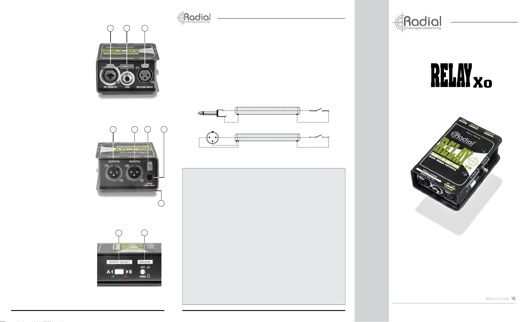
1. JR1 REMOTE: Locking XLR
and ¼” combo jack used to
connect a remote switch. Use with
footswitches, MIDI contact closures
or the Radial JR1.
2. REMOTE LINK: Used to link
the switching of additional Relay
Xo units. Allows stereo and multichannel switching systems.
3. MIC/LINE INPUT : Balanced XLR
input. The Relay Xo signal path is
100% passive. Audio signals will
pass through unchanged without
added noise or distortion.
4. OUTPUT-B: Alternate balanced
XLR output. This output is active
when the select switch is pressed
inward or when a remote switch is
closed. The B LED illuminates when
the output is active.
5. OUTPUT-A: Main balanced XLR
output. This output is active when
the switch is in the outward position
or when a remote switch is open.
The A LED illuminates when the
output is active.
6. CABLE CLAMP: Prevents
accidental power disconnection by
locking down the AC adapter cable.
7. POWER JACK: Connection for
the included 15 volt (400mA) AC
power adapter
8. FULL-BOTTOM NO-SLIP PAD:
This provides electrical isolation
and plenty of ‘stay-put’ friction to
keep the Relay Xo in one place.
9. OUTPUT SELECT: This switch
toggles the Relay Xo’s outputs.
Two LED indicators display which
output is active.
10. GROUND LIFT: Disconnects
pin-1 (ground) on the input XLR
jack to help reduce hum and buzz
caused by ground loops.
Radial Engineering Ltd.
®
1
2 3
True to the Music
®
True to the Music
Relay Xo specifi cations
Audio circuit type: ............................................... Passive balanced A/B switcher
Switch: ................................................................ Electronically controlled relay
XLR input and outputs: ....................................... AES standard; pin-1 ground,
Ground lift: .......................................................... Lifts pin-1 on the XLR input
Power: ................................................................15V/400mA, 120V/240 power
pin-2 (+), pin-3 (-)
adapter included
™
REMOTE AB SWITCHER
Wiring diagram for custom JR1 REMOTE switch
Tip
Sleeve
6 7
4
5
RADIAL ENGINEERING LTD. (“Radial”) warrants this product to be free from defects in material and
workmanship and will remedy any such defects free of charge according to the terms of this warranty.
8
9
10
Radial will repair or replace (at its option) any defective component(s) of this product (excluding fi nish and
wear and tear on components under normal use) for a period of three (3) years from the original date of
purchase. In the event that a particular product is no longer available, Radial reserves the right to replace
the product with a similar product of equal or greater value. In the unlikely event that a defect is uncovered,
please call 604-942-1001 or email service@radialeng.com to obtain an RA number (Return Authorization
number) before the 3 year warranty period expires. The product must be returned prepaid in the original
shipping container (or equivalent) to Radial or to an authorized Radial repair center and you must assume
the risk of loss or damage. A copy of the original invoice showing date of purchase and the dealer name
must accompany any request for work to be performed under this limited and transferable warranty. This
warranty shall not apply if the product has been damaged due to abuse, misuse, misapplication, accident
or as a result of service or modifi cation by any other than an authorized Radial repair center.
THERE ARE NO EXPRESSED WARRANTIES OTHER THAN THOSE ON THE FACE HEREOF
AND DESCRIBED ABOVE. NO WARRANTIES WHETHER EXPRESSED OR IMPLIED, INCLUDING
BUT NOT LIMITED TO, ANY IMPLIED WARRANTIES OF MERCHANTABILITY OR FITNESS FOR
A PARTICULAR PURPOSE SHALL EXTEND BEYOND THE RESPECTIVE WARRANTY PERIOD
DESCRIBED ABOVE OF THREE YEARS. RADIAL SHALL NOT BE RESPONSIBLE OR LIABLE FOR
ANY SPECIAL, INCIDENTAL OR CONSEQUENTIAL DAMAGES OR LOSS ARISING FROM THE USE
OF THIS PRODUCT . THIS WARRANTY GIVES YOU SPECIFIC LEGAL RIGHTS, AND YOU MA Y ALSO
HAVE OTHER RIGHTS, WHICH MAY VARY DEPENDING ON WHERE YOU LIVE AND WHERE THE
PRODUCT WAS PURCHASED.
Radial Engineering Ltd.
12
3
Cable Shield
Cable Shield
RADIAL ENGINEERING 3 YEAR
TRANSFERABLE LIMITED WARRANTY
Open Switch
Open Switch
Relay Xo
USER GUIDE
Radial Engineering Ltd.
1588 Kebet Way, Port Coquitlam BC V3C 5M5
tel: 604-942-1001 • fax: 604-942-1010
info@radialeng.com • www.radialeng.com
Relay Xo™ User Guide - Part# R870 1275 00 • © Copyright 2014 all rights reserved
Specifi cations and appearance are subject to change without notice.
Relay Xo™
™
www.radialeng.com
Page 2
OVERVIEW
Thank you for purchasing the Radial Relay Xo, a simple yet effective switching
device designed to toggle a microphone or other balanced audio signal
between two channels on a PA system. As with all products, getting to know
the feature set is essential if you intend to get the most out of the Relay.
Please take a minute to read through this short manual. If you are left with
unanswered questions, feel free to send us an email at info@radialeng.com
and we will do our best to reply in short order. Now get ready to remotely
switch to your heart’s content!
The Relay is basically a 1-in, 2-out straight-wire switcher for balanced audio.
There is no transformer or buffering circuitry in between the input and outputs.
This means the Relay Xo can not introduce distortion or noise into the source
signal and allows it to be used with mic or line level sources. A link feature
allows multiple Relay Xo units to be combined and switch stereo or multichannel audio systems. Switching can be done on the Relay Xo, via remote
footswitch or by MIDI contact closure.
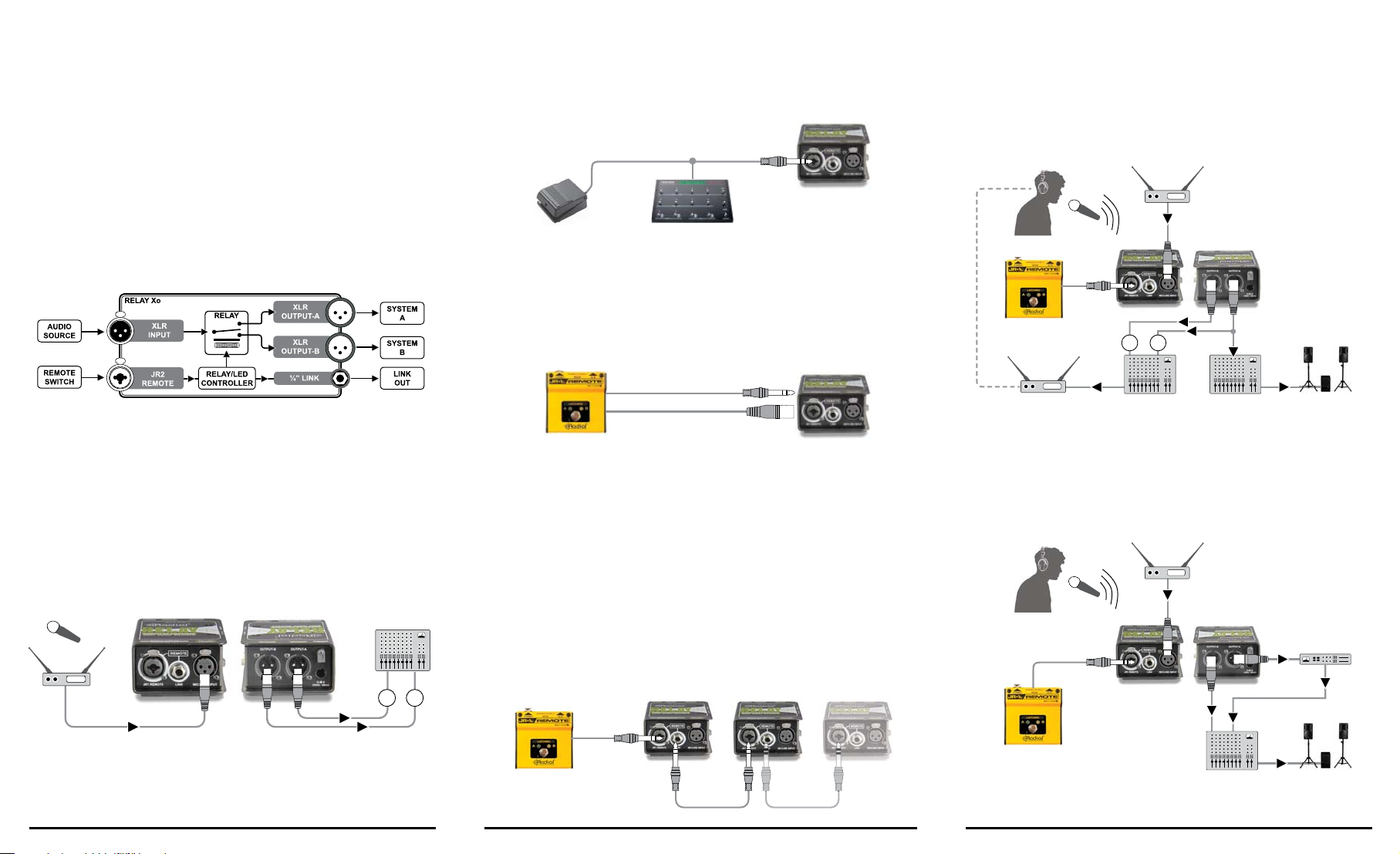
REMOTE CONTROL
The Relay Xo’s outputs may be toggled remotely using an external ‘latching’ or
‘momentary’ switch connected to the ‘JR1 REMOTE’ jack. This combo jack features
a locking XLR and ¼” input. The ¼” connection works with any standard footswitch
such as a momentary sustain pedal or a latching amplifi er channel switch. It can also
work with any device equipped with a ¼” contact-closure output like a MIDI controller.
Simple footswitches and contact-closure devices like MIDI
controllers use ¼” cables to connect to the Relay Xo.
Both the combo jack’s XLR and ¼” connection work with the optional Radial JR1
footswitches. The JR1 footswitches are also equipped with locking XLR jacks allowing
you to use either type of cable. Locking connectors are benefi cial on busy stages as
it reduces the opportunity for a connection to come lose during a performance. The
JR1 footswitches are available in momentary (JR1-M) or latching (JR1-L) formats to
address various needs on stage and include A/B LED status indicators.
USING THE RELAY XO FOR A TALK-BACK SYSTEM
A momentary footswitch, like the optional JR1M, is recommended when using
the Relay Xo as a talk-back or communication mic switcher as this requires
holding the footswitch ‘on’ to speak with other band members or the crew.
Releasing the footswitch reverts back to normal. This avoids accidentally
leaving the Relay on ‘communication mode’ which could otherwise prove to
be embarrassing if left on.
Wireless
Receiver
JR1-M
Momentary
AB
MAKING CONNECTIONS
Before making any connections, make sure volume levels are turned off or
down and/or power is turned off. This will help you avoid turn-on or power-on
transients that could harm more sensitive components like tweeters. There
is no power switch on the Relay. Simply plug in the included 15 VDC supply
and it will spring to life. A cable clamp next to the power jack can be employed
to prevent accidental disconnection.
The audio input and outputs employ balanced XLR connections wired to the
AES standard with pin-1 ground, pin-2 hot (+), and pin-3 cold (-). Connect
your source device such as a microphone or wireless mic receiver to the
Relay Xo input jack. Connect the A and B outputs to two inputs on a mixer.
A B
Switching between the outputs can be done using the OUTPUT SELECT push
button on the side panel. Start by setting up channel-A. Set the AB selector
switch set to the A position (outward). Speak into the mic while slowly bringing
up the volume levels. To set up the channel-B depress the AB selector switch
to toggle the output. The LED indicators illuminate to display the active output.
Relay Xo
™
The JR1 uses either ¼” or locking XLR cable to connect to the Relay Xo.
Because footswitches are either momentary or latching it’s important to understand
how the Relay Xo works with these two types of switches. A momentary
footswitch, like the JR1-M or a keyboard sustain pedal, will toggle to output-B
only while held down. Once the momentary footswitch is released the Relay Xo
will toggle back to output-A. A latching footswitch, like the JR1L or an amplifi er
AB channel selector switch will toggle the Relay each time it is pressed. One press
will toggle to output-B. Pressing again with toggle back to output-A.
MULTI-CHANNEL SWITCHING
Two or more Relay Xo units can be switched in tandem by simply bridging the
devices together using a standard ¼” patch cable. The LINK feature allows
switching of stereo and multi-channel audio systems from a single switch. Connect
a footswitch to the fi rst unit or use the side panel OUTPUT SELECT switch.
Connect the ¼” LINK jack on the fi rst unit to the JR1 REMOTE jack on the second.
You can connect as many successive units as you like this way.
JR1-M or JR1-L ¼” Link Cables
Relay Xo™ Relay Xo™
Radial Engineering Ltd.Radial Engineering Ltd. Radial Engineering Ltd.
In-ear
Transmitter
In-ear
Monitor Mixer
FOH
Mixer
House
PA System
USING THE RELAY XO TO SWITCH MIXER CHANNELS
Using a latching switch, like the optional JR1L, is suggested when switching
between audio channels on a PA system. Switching channels lets you
alternate between a dry channel for communication with the audience and
a wet channel with echo and reverb for singing.
Wireless
Receiver
Digital
Effects
JR1-L
Latching
Dry Ch.
FOH
Mixer
Wet Ch.
House
PA System
 Loading...