

Page 1
™
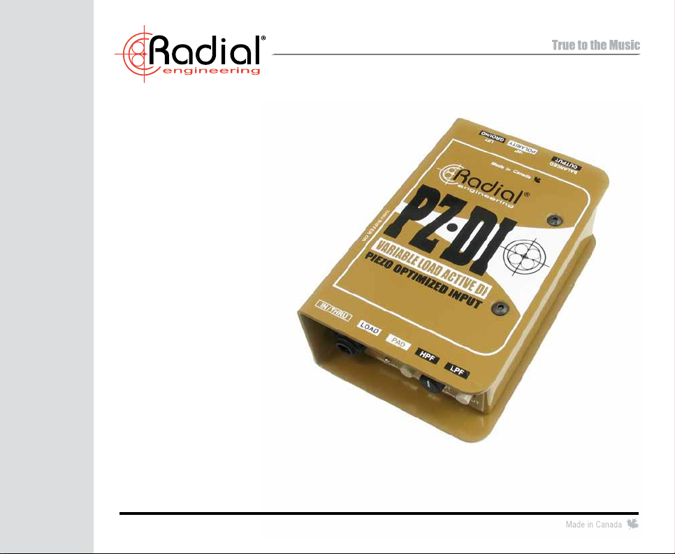
PZ-DI
Piezo Optimized
Active Direct Box
USER GUIDE
Radial Engineering Ltd.
1588 Kebet Way, Port Coquitlam BC V3C 5M5
Tel: 604-942-1001 • Fax: 604-942-1010 • Email: info@radialeng.com
www.radialeng.com
Page 2

Page 3

™
PZ-DI
Piezo Optimized
Active Direct Box
TABLE OF CONTENTS PAGE
Introduction ..............................................................................1
Input & output panel features ..................................................2
Overview & load adjustment ....................................................3
Powering the PZ-DI .................................................................4
Connecting the JPC.................................................................5
Using an amplier ....................................................................6
Using the PAD and low-cut lter ..............................................7
Using the polarity and ground lift .............................................8
Block diagram and specications ............................................9
Warranty ....................................................................Back cover
INTRODUCTION
Thank you for purchasing a Radial PZ-DI, one of the most innovative direct boxes ever made! Unlike others that are a
‘one-size-ts-all’ the PZ-DI has been designed from the ground up to solve the problems that are common to piezo-electric
transducers while signicantly enhancing the musical performance when used with other pickups or instruments.
This manual has been written to provide you with a full understanding of how to use the PZ-DI and get the most out of
it. Please take a few minutes to read it all the way through. You will nd that there are several innovative features built-in
that can greatly enhance your enjoyment and the outcome. If by chance you do not nd everything you need within these
pages, please visit the PZ-DI FAQ page on our web site. This is where we post the latest updates and questions from
users like you. If after that you still do not nd what you are looking for, feel free to send an email to info@radialeng.com
and we will do our very best to reply to you in short order.
Now get ready to hear that orchestra like never before!
Radial Engineering Ltd. PZ-DI™ User Guide
1
Page 4
1 2 3 4 5 6 7 8 9 10 11 1312
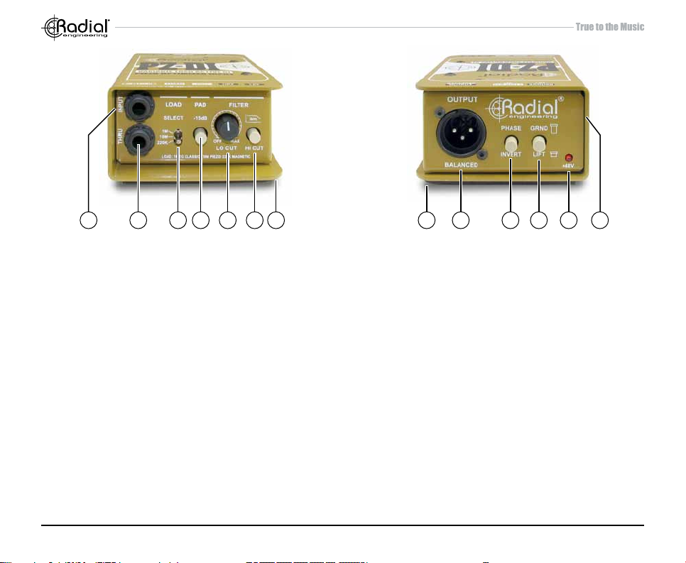
INPUT PANEL
1. INPUT: ¼” hi-Z input used to connect the instrument to the PZ-DI.
2. THRU: ¼” throughput used to feed an on-stage instrument amplier.
3. LOAD: 3-position switch lets you adjust the input impedance to
optimize the load for the type of pickup being used. Set to 220k
ohm for magnetic pickups, 10 meg-ohm for piezo transducers and
1 meg-ohm to replicate traditional DIs.
4. PAD: Reduces the input sensitivity by -15dB enabling the PZ-DI
to be used with high output instruments such as active basses or
keyboards.
5. LO-CUT: Variable high-pass lter is used to remove unwanted
resonance and size the instrument to suit. Variable from 5Hz to
500Hz.
6. HI-CUT: Used to warm up the sound of active instruments that often
contain excessive high frequencies.
7. BOOK-END DESIGN: Creates protective zone around connectors, switches and potentiometers to prevent damage.
Radial Engineering Ltd. PZ-DI™ User Guide
2
OUTPUT PANEL
8. NO SLIP PAD: Provides electrical and mechanical isolation while
keeping the PZ-DI from sliding around on busy stages.
9. XLR OUT: Balanced low impedance output used to connect the
PZ-DI to the mixing console. Allows long cable runs in excess of
100 meters (300 feet) without noise.
10. PHASE: 180° polarity reverse toggles pin-2 and pin-3 at the XLR
output. Used to tame acoustic hot spots on stage and help reduce
resonant feedback.
11. LIFT: Ground lift switch disconnects the ground from the audio
signal path and helps eliminate hum and buzz caused by ground
loops.
12. 48V: Provides visual status of 48V phantom power. When the LED
is on, the PZ-DI is being fed 48 volts from the console.
13. THRU BUFFER ON: Buffers the signal before it is sent to the thruput connector for use with piezo transducers or when using longer
cable runs.
Page 5

OVERVIEW
LOAD
SELECT
LOAD
SELECT
Upon rst look, the Radial PZ-DI appears to be similar to most other direct boxes. This is true. You can use the PZ-DI
just as you would a Radial J48 or one of our other direct boxes. Where it differs is that it has been optimized for use with
piezo-electric pickups as these are the most problematic of all. A three position load switch lets you match the PZ-DI’s
input with the type of pickup you are using. This eliminates the peaks, squawk and limited bandwidth of the transducer for
a more natural sound. Since the PZ-DI will likely be used on acoustic or orchestral instruments, we have also enhanced
the control set to enable you to precisely control the low end, warm up the top end and help eliminate feedback due to hot
spots on stage. And somehow we still managed to make it easy to use! So let’s get started...
Adjusting the load
One of the coolest features on the PZ-DI is the load adjustment switch. This works with the PAD to let you interface a wide
variety of pickups or sources to both maximize the frequency response and minimize distortion. There are three settings
to choose from. Set the load switch to match the type of pickup or instrument you are using.
220k for magnetic pickups: Over the years, we have found that 220k-ohms on a solid state buffer provides a similar
sound to connecting to a 1 meg-ohm input on a tube guitar amp. The Radial J48 employs this input impedance for this
reason and the PZ-DI follows suit. So if you are connecting a Fender Jazz bass to the PZ-DI, set the load to 220k.
10M
220K
1M
10 meg for piezos: Most manufacturers employ a 1 meg-ohm input on their interfaces. This gives you relatively
high input impedance without too much noise. The problem is that piezo transducers tend to sound very peaky,
squawk and end up losing bottom-end unless they see a much higher load. The 10 meg-ohm input on the PZ-DI
really makes them sound marvellous.
10M
220K
1M
1 meg for traditional DIs: Since Leo Fender made his rst amps, most companies have followed suit with a 1
meg-ohm input impedance. This traditional load will brighten up a Fender bass or give you more air if you are going
to reamp using your Les Paul. You may also nd this will give you the tone you want when using the PZ-DI on an
old Rhodes piano.
10M
220K
1M
PAD for high output instruments: When you engage the PAD, the PZ-DI’s input sensitivity will be reduced by 15dB and
the load will drop to 50k-ohms making it ideal for buffered devices such as digital keyboards, drum machines or active
basses and guitars. The lower impedance reduces susceptibility to noise while the lower input sensitivity will prevent high
output devices from overloading the PZ-DI’s circuit - resulting in less distortion.
Radial Engineering Ltd. PZ-DI™ User Guide
3
LOAD
SELECT
Page 6

POWERING UP
Always make sure levels are turned off before making connections. This will help eliminate turn-on transients that can
harm more sensitive components such as tweeters. You
should also test at low volumes before turning up.
The PZ-DI does not require a battery or power supply to
make it work. It uses 48V phantom from the mixing console.
All you do is plug it in, turn the phantom power on at the
mixing desk and the power LED on the PZ-DI will illuminate
to let you know you are set to go.
The +48V LED will illuminate when
phantom power is present.
LOAD: Set the load switch to match the type of pickup or instru-
ment you are using.
PAD: Set to the outward position to start. Depress to engage
the PAD if you detect clipping. High output sources like
digital keyboards and active basses are more likely to
cause clipping.
LO CUT: Start with the control turned fully counter-clockwise to
SELECT
1M
10M
220K
LOAD
PAD
-15dB
OUT OUT
OFF
LO CUT
FILTER
MAX
HI CUT
3kHz
the OFF (bypass) position.
HI CUT: Set to the outward position to bypass the high frequency
lter.
Radial Engineering Ltd. PZ-DI™ User Guide
4
Page 7

MAKING CONNECTIONS
Connect the source instrument to the input using a standard ¼” instrument cable, set the appropriate load and connect
the XLR output to your mixer using a standard mic cable. The PZ-DI will convert the high-impedance unbalanced signal
to a balanced low impedance signal that will properly interface with the audio system. This will enable you to run long
balanced cables without noise or signal loss.
Radial Engineering Ltd. PZ-DI™ User Guide
5
Page 8

USING AN AMPLIFIER
If you are using an on-stage amplier for personal monitoring, use the THRU to make this connection. This is basically
a pass-through that takes the original signal and feeds it
to your amp.
SIDE ACCESS BUFFER THRU ON SWITCH
The PZ-DI features a side access buffer ON ‘set & forget’
switch that allows the thru-put connector to be used two
ways.
Buffer Off
When OFF (out position) the direct signal from the source
instrument is sent thru to the amp. This setting is typically
used with an active instrument such as an acoustic guitar
or passive instrument such as a bass where you do not
want to ‘amplify’ the signal before it reaches the stage
amp. This sends the original ‘dry’ signal from the instrument
without the buffer.
Buffer On
When on (in position), the signal is buffered (or amplied)
before it is sent to the thru-put connector. This is typically
used when the source is a piezo transducer and the buffered
signal at the thru-put will benet the stage amp with a more
appropriate output. Buffering the signal also allows longer
cable runs with less noise.
Buffer Off
Passive Bass
Buffer On
Piezo Pickup
Radial Engineering Ltd. PZ-DI™ User Guide
6
Page 9

USING THE -15DB PAD
As previously mentioned, the -15db PAD is used to reduce the PZ-DI’s input sensitivity. This lowers the signal level while
also lowering the impedance to reduce susceptibility to noise. Most instruments do not produce enough output to overload
the PZ-DI. However, if you are using high output devices like active basses, digital pianos or maybe a headphone output
from a computer, engaging the PAD will help by avoiding overload which in turn can cause the circuit to distort. Reducing
distortion can often help reduce feedback!
USING THE LOW-CUT FILTER
One of the cool features on the PZ-DI is the variable low frequency
lter. This low-cut lter does exactly that, it cuts the bass frequencies
and allows the highs to pass. When using acoustic instruments on
a live stage, the low frequencies generated by the PA system can
often cause the top of the instrument to resonate and feedback due
to the vibrations. This is all the more acute when using a top-mounted
piezo-electric device that is afxed on the top or the bridge. Activating
the low-cut lter reduces the bass frequencies going to the PA which
in turn, reduces resonant feedback.
PZ-DI Low-Cut Filter Response
+10
+5
+0
-5
-10
-15
20 20k50 100 200 500 1k 2k 5k 10k
Hz
Start by setting the lter control completely counter-clockwise. Slowly turn it clock-wise until you notice the bass roll off.
Turn back a bit and you are set. The lter position is usually set in proportion to the size of the instrument whereby larger
instruments such as a contrabass will be set with more bass, while a cello or violin will have less.
Radial Engineering Ltd. PZ-DI™ User Guide
7
Page 10

PZ-DI Hi-Cut Filter Response
USING THE HI-CUT FILTER
Another extra feature that is included on the PZ-DI is a
high frequency lter. This is used to warm up the sound of
the instrument by gently rolling off high frequencies above
3kHz while allowing lower frequencies to pass. The high-cut
(low pass) lter is primarily used on buffered instruments
such as acoustic guitars or violins that have a built-in pre-
amp. Engaging the lter will smooth out the top end and
+10
+5
+0
-5
-10
-15
-20
20 20k50 100 200 500 1k 2 k 5k 10k
Hz
eliminate the edginess that can be problematic with some
lesser quality preamps.
USING THE 180° POLARITY REVERSE
One of the most challenging aspects to using orchestral
instruments on stage is managing feedback. This is particu-
larly difcult when sharing the stage with electric guitars and
drums. As you increase the level of the acoustic instrument,
sound waves from the PA, monitors, and wall boundaries
combine at certain frequencies to create hot-spots known
as room modes. This can cause feedback. The 180° polarity
reverse comes to the rescue by enabling you to reverse
the electrical phase which in turn can move the room mode
NORMAL PHASE INVERTED PHASE
out of the way. Best of all, it eliminates feedback without
resorting to using some form of radical lter.
USING THE GROUND LIFT SWITCH
One of the unique features that is built into the PZ-DI is the power system. This converts 48V phantom power using a
switching supply that increases the signal handling capability while enabling the ground lift switch to be engaged without
disconnecting the 48V phantom power. This means that should you encounter a ground loop, you can lift the ground
without having to resort to an external power supply or battery.
Radial Engineering Ltd. PZ-DI™ User Guide
8
Page 11
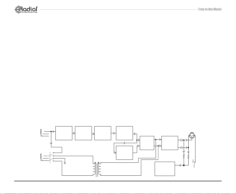
PZ-DI SPECIFICATIONS AND BLOCK DIAGRAM
PZ-DI Block Diagram
Circuit type: ............................................... Proprietary analog circuit with low-noise FET op-amp
Frequency Response: .............................. 20Hz ~ 20kHz
Maximum input level: ................................ +10dBu
THD+N: .................................................... 0.02%
Dynamic range: ........................................ 105dB
Equivalent input noise: ............................. -98dBu
Maximum Gain: ........................................ +4.6dB
Intermodulation distortion: ........................ 0.04%
Input impedance: ...................................... 10M/1M/220K-Ohms
PAD: ......................................................... -15dB
Input impedance with PAD on: ................. 50K-Ohms
Output impedance: ................................... 200 Ohms - nominal
Power requirement: .................................. +48V Phantom Power
XLR conguration: .................................... AES standard (pin-1 ground, pin-2 +Hot, pin-3 -Cold)
FCC approval: .......................................... Complies with section 15 of the FCC Rules
Warranty: .................................................. Radial 3-year, transferable
INPUT
THRU
IMPEDANCE
SELECTOR
DIRECT
BUFFERED
LOOP
SELECT
PAD
SWITCH
CLASS A
FET
BUFFER
Radial Engineering Ltd. PZ-DI™ User Guide
VARIABLE
FREQUENCY
HIGH PASS
FILTER
PHASE
INVERTER
9
LOW
PASS
FILTER
POLARITY
REVERSE
SWITCH
PHANTOM
SOURCE
ISOLATED
POWER SUPPLY
OUTPUT
GROUND LIFT
Page 12

RADIAL ENGINEERING
3 YEAR TRANSFERABLE WARRANTY
RADIAL ENGINEERING LTD. (“Radial”) warrants this product to be free from defects in material and workmanship and will remedy
any such defects free of charge according to the terms of this warranty. Radial will repair or replace (at its option) any defective
component(s) of this product (excluding nish and wear and tear on components under normal use) for a period of three (3) years
from the original date of purchase. In the event that a particular product is no longer available, Radial reserves the right to replace the
product with a similar product of equal or greater value. In the unlikely event that a defect is uncovered, please call 604-942-1001 or
email service@radialeng.com to obtain a RA number (Return Authorization number) before the 3 year warranty period expires. The
product must be returned prepaid in the original shipping container (or equivalent) to Radial or to an authorized Radial repair center
and you must assume the risk of loss or damage. A copy of the original invoice showing date of purchase and the dealer name must
accompany any request for work to be performed under this limited and transferable warranty. This warranty shall not apply if the
product has been damaged due to abuse, misuse, misapplication, accident or as a result of service or modication by any other than
an authorized Radial repair center.
THERE ARE NO EXPRESSED WARRANTIES OTHER THAN THOSE ON THE FACE HEREOF AND DESCRIBED ABOVE. NO
WARRANTIES WHETHER EXPRESSED OR IMPLIED, INCLUDING BUT NOT LIMITED TO, ANY IMPLIED WARRANTIES OF
MERCHANTABILITY OR FITNESS FOR A PARTICULAR PURPOSE SHALL EXTEND BEYOND THE RESPECTIVE WARRANTY
PERIOD DESCRIBED ABOVE OF THREE YEARS. RADIAL SHALL NOT BE RESPONSIBLE OR LIABLE FOR ANY SPECIAL, INCIDENTAL OR CONSEQUENTIAL DAMAGES OR LOSS ARISING FROM THE USE OF THIS PRODUCT. THIS WARRANTY GIVES
YOU SPECIFIC LEGAL RIGHTS, AND YOU MAY ALSO HAVE OTHER RIGHTS, WHICH MAY VARY DEPENDING ON WHERE
YOU LIVE AND WHERE THE PRODUCT WAS PURCHASED.
This device complies with section 15 of the FCC Rules.
Operation is subject to the following two conditions: (1) this
device may not cause harmful interference, and (2) this
device must accept any interference received, including
interference that may cause undesired operation.
Radial Engineering Ltd.
1588 Kebet Way, Port Coquitlam BC V3C 5M5
Tel: 604-942-1001 • Fax: 604-942-1010 • Email: info@radialeng.com
Radial PZ-DI™ User Guide - Part #: R870 1236 10 Copyright © 2016, all rights reserved.
Appearance and specications subject to change without notice.
 Loading...