

Page 1
True to the Music
OX8
User Guide
Eight Channel • Transformer Isolated • Microphone Splitters
Radial Engineering Ltd.
1588 Kebet Way, Port Coquitlam BC V3C 5M5
tel: 604-942-1001 • fax: 604-942-1010
www.radialeng.com
email: info@radialeng.com • web: www.radialeng.com
Specications and appearance are subject to change without notice.
© Copyright 2009, all rights reserved.
www.radialeng.com
Page 2

This page left blank
Page 3

True to the Music
OX8
User Guide
Eight Channel • Transformer Isolated • Microphone Splitters
Table of Contents Page
OX8 Introduction......................................................1
OX8 Design Concept ...............................................2
Basics - What is a Splitter........................................2
How a Transformer Works .......................................2
What is a Ground Loop............................................2
Signal Flow Block Diagram......................................3
Feature Set ..............................................................4
Applications .............................................................6
Grounding Options ..................................................7
CX8 Introduction ......................................................8
CX8 Installation .......................................................9
INTRODUCTION
Congratulations on your purchase of a Radial microphone splitter. This manual covers installation and operation of the OX8 microphone splitter. We recommend that you take a few minutes to read through this manual in order to familiarize yourself with the many
innovative features that are built in.
Should you have questions or applications not covered in this manual, we invite you to log onto the Radial web site at www.radialeng.
com to check the FAQ section for the latest updates. Of course, you can also send us an email at info@radialeng.com.
OX8 DESIGN CONCEPT
The Radial OX8 is an eight channel, balanced microphone splitter in a compact 1RU package that divides the mic signals three ways;
to a direct output; a direct output with ground lift; and an isolated output. A high performance bridging transformer is used on the isolated output to eliminate hum and buzz caused by ground loops.
Splitting microphone signals is a straight forward concept. It’s most common in sound reinforcement and live recording when the onstage microphones must be split to feed two mixing consoles. When done improperly, splitting a signal can dull frequency response,
lower the output and worst of all, cause ground loops that produce buzz and hum. To avoid these pitfalls, sound reinforcement companies have been building custom “splitter-snakes” for many years.
The OX8 is an off-the-shelf splitter for the rest of us allowing virtually anyone to design and assemble a splitter-snake with plug-n-play
simplicity and professional audio quality without the need for custom metal work or complex soldering.
Radial Engineering Ltd. OX8™ User Guide
1
Page 4
BASICS
What is a Mic Splitter
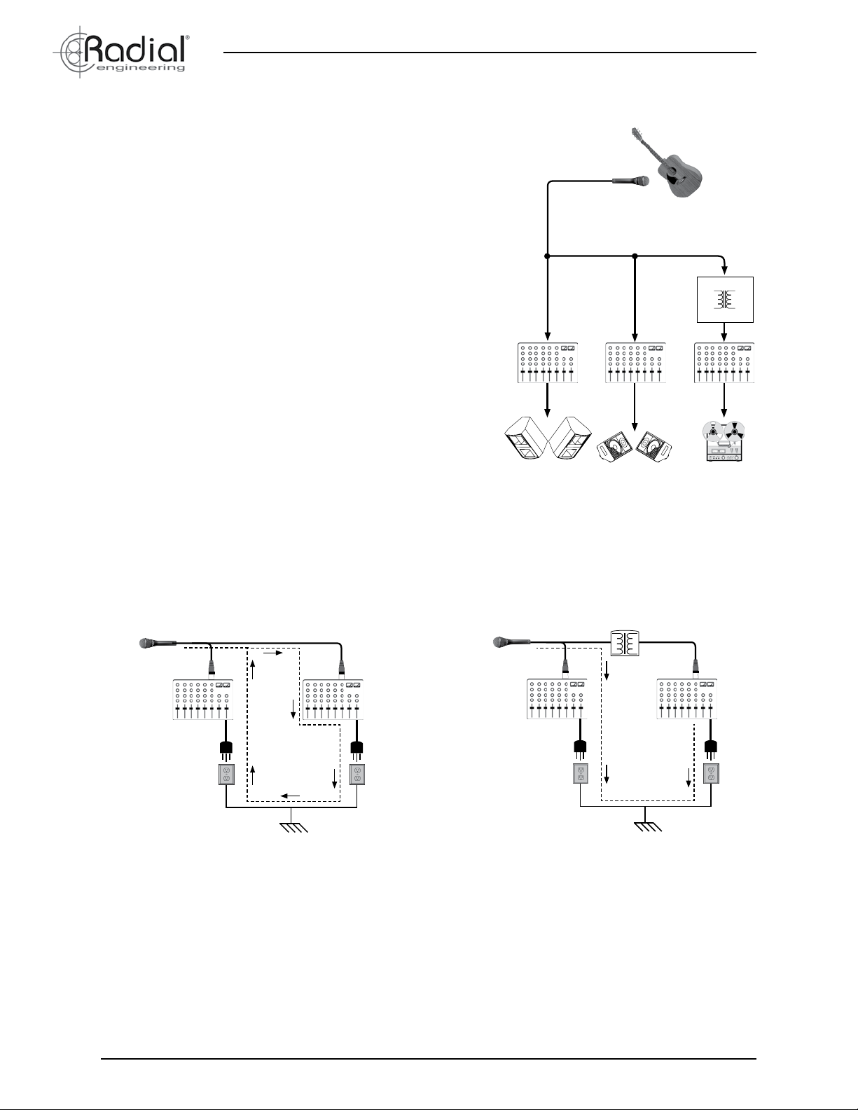
In modern concert production there are often two separate sound systems. The main PA covers the audience or “house” while a monitor system covers the stage so the performers can hear. A third system may be
added if the concert is to be recorded. Each system requires it’s own mixing console because the mix that sounds good in the house simply won’t
work for the monitors or be suitable for a recording. A mic splitter provides
the means to split the original signal from the on-stage microphones and
send it to the various systems, main PA, monitors and recording, so that
each can get a clean, unaffected signal directly from the mic.
True to the Music
Stage Microphone
However, splitting microphone signals is not as simple as just wiring the
microphones to all the consoles. Issues such as impedance loading,
ground loops and phantom power can degrade the signal and introduce
noise. To solve these issues the OX8 uses high performance audio isola-
Isolation
Transformer
tion transformers to decouple the signal passing through it and eliminate
ground loops that cause hum and buzz in audio systems.
Inside a Transformer
A transformer consists of two coils of wire in close proximity to one another wound around a metal core. One coil is the transformers input (primary), the other coil is the output (secondary). A transformer is said to
electrically isolate, or decouple, the input from the output because there
is no physical connection between the primary and secondary windings.
When the primary winding is energized by the mic signal, a magnetic eld
is produced and the lines of force cut across the turns of the secondary
winding. Alternating current (AC) which makes up the audio program is
Main PA Recorder
Monitors
transduced from one winding to another through induction. Direct current
(DC) which is responsible for buzz and hum in sound systems, is blocked
by the transformer eliminating noise caused by ground loops.
Those Darn Ground Loops
A ground loop is created when an audio system has multiple paths to ground, often called earth. This situation can occur when two
AC powered audio devices, such as two mixing consoles, are plugged into different power circuits and connected together via a signal
cable. Both audio devices have a path to ground through the third prong on the AC-mains cable. The signal cable completes the loop
by connecting the devices together through the signal cable’s shield.
Transformer Isolation
Ground Loop Path
Earth
Earth
Once the loop is complete there is the electrical potential for DC voltage to ow through it. This potential is caused by the interaction
between devices with different ground voltage references and allows unwanted spurious current to ow through the shields of the
signal cables. This ow of DC voltage creates noise in the signal wires through induction and capacitance at the base frequency of 50
or 60 Hz (hum) and the upper harmonics of 120 Hz, 240 Hz, etc. (buzz). Isolating or decoupling the audio signal with a transformer at
a point between the two devices is the best way to block the unwanted ow of ground-potential currents and eliminate hum and buzz
in audio systems.
Sound Quality
Besides isolation to prevent hum and buzz, audio transformers must sound brilliant and sound quality is what sets Eclipse® and
Jensen® transformers apart. Designed for pro-audio applications, they include a host of features not found in general purpose audio
transformers. A core material of nickel-iron allows ultra high input levels before saturation, linear frequency response, excellent bandwidth and near zero phase distortion. Consistent unit-to-unit performance is achieved through precision computer controlled winding.
The core is sealed inside a mu-metal can which provides enhanced shielding from electromagnetic interference. The built-in Bessel
low pass lter removes ultrasonic distortion that can mask natural sound and cause ear-fatigue.
2
Radial Engineering Ltd.
OX8
™
User Guide
Page 5

True to the Music
SIGNAL FLOW
Take a moment to follow the signal path through the block diagram below.
1
Inputs 1-8
DB-25
Front Panel
XLR x 8
Inputs 1-8
Euroblock
-20dB
PAD
DB-25
Euro
Block
2 3 4
Direct Output and
Return Path for 48V
1
Parallel Inputs
For exibility, the OX8 has three paralleled inputs.
• Female XLR connectors on the front panel
• 25 pin D-SUB (DB-25) on the rear panel
• Euroblocks screw terminals on the rear panel (Set of eight
Euroblocks terminals sold separately, Order # R800 8050).
Direct Output
2
The DIRECT output is the primary “straight through” output
and provides a return path for 48V phantom power for condenser microphones and active direct boxes. In the diagrams
we refer to the main FOH console as connected to the DIRECT output. In fact it doesn’t matter which console, main or
monitor is connected to DIRECT as long as it is the only console which will supply phantom power. The DIRECT output
is paralleled to DB-25 and Euroblocks terminals for exibility.
3
Auxiliary Direct Output with Ground Lift
The DIRECT OUT WITH GROUND LIFT is an auxiliary output
that uses eight front panel switches to lift the ground. This
output may be patched to another audio system that may or
may not be transformer isolated itself. The DIRECT WITH
GROUND LIFT output is paralleled to DB-25 and Euroblocks
terminals.
Front Panel
Ground Lift
Auxiliary Direct Output
with Ground Lift
Internal
Ground
Lift
DB-25 DB-25
Euro
Block
Transformer
Isolated Output
4
Isolated Output
Isolation
Transformer
Euro
Block
The ISOLATED outputs use eight precision audio isolation
transformers to decouple the mic signals from the DIRECT
outputs. This output may be patched to a separate audio system without creating ground loops. The ISOLATED output is
paralleled to DB-25 and Euroblocks terminals.
-20dB PAD
The front panel PAD switch can prevent transformer overload when connecting high output devices like synthesizers
and drum machines. Engaging the PAD reduces the level by
-20dB for that particular channel at the ISOLATED output.
Isolation Transformer
After the PAD the signal is fed to the isolation transformer
where the mic signal is decoupled to eliminate noise from
ground loops. For the most exibility when designing technical
ground systems, each transformer features an internal switch
allowing the signal ground to connect around the transformer.
RF Filter (not shown in the diagram)
The three paralleled inputs employ a RF network lter on their
ground paths to prevent unused inputs from acting like antennas when the ground is lifted. Any radio frequencies picked up
by an open pin will be shunted to ground.
Radial Engineering Ltd. OX8™ User Guide
3
Page 6

INTRODUCTION
True to the Music
1 2 3 4
65 7 8 9 10
11 12 13 15 16 1714
1. XLR Inputs - Front panel female XLR jacks allow easy
connection of individual signals. Rugged, glass-reinforced
nylon construction for reliable connections.
2. PAD -20dB - Prevents transformer overload when connecting high output devices. Only the ISOLATED output is affected by the PAD.
3. Front Panel Lift Switch - Disconnects the ground path at
the DIRECT WITH GROUND LIFT auxiliary output. Using
the front panel ground lift can eliminate ground loop noise
between equipment connected to the OX8 direct outputs.
4. Easy ID label zones - For dry-erase markers or wax pencil
identication. Handy when using several OX8 at a time.
5. Internal Chassis Ground Lift - Input connectors are
100% isolated from the chassis, but an internal switch is
provided to connect signal ground (pin-1) to the chassis
without modifying the OX8. By default, this switch is factory
set to “lifted” allowing the chassis to “oat” ungrounded and
should remain this way unless a specic grounding scheme
requires the signal ground to be tied to the chassis.
6. Military Grade PCB - The dual layer circuit board is manufactured with plated through holes and secured with 8
standoffs.
7. Transformers - Each transformer is mounted directly on
the PCB in close proximity to the input for the shortest possible signal path. Choice of standard Eclipse or optional
Jensen transformers.
8. Heavy-duty Switches - Front panel switches are metal encased and rated at 20,000 operations.
9. Internal Ground Lift - Each channel features an internal
switch that, by default, is set to “lifted” so the transformer
can isolate ground potential voltages. It may be used by
system designers to accommodate specic grounding
schemes when desired.
10. 14-Gauge Chassis - Made extra tough with heavy gauge
steel and welded corners to provide excellent shielding and
durability. Finished in baked enamel.
11. Isolated Output - This output is transformer isolated to
block noise caused by ground loops and is wired in parallel
to DB-25 and Euroblocks terminals.
12. Direct With Ground Lift - This is an auxiliary output wired
in parallel with the DIRECT output. The signal grounds
may be disconnected using the front panel LIFT switch.
This output is wired parallel to the DB-25 and Euroblocks
terminals.
13. DB-25 Pin-out Diagram - The pin-out for the female DB-25
connector is diagramed on the rear panel. All DB-25 connectors follow the Tascam standard for eight channel analog signal interface.
14. Euroblock Sockets - These panel sockets receive 12-pin
Euroblock screw terminals. Each Euroblock connects four
channels with bare wire termination and facilitate custom
options like interfacing a connector panel or multi-pin disconnect. Euroblocks screw terminals are optional and must
be ordered separately. (Radial order # R800 8050)
15. Direct Output - This output passes signal through the OX8
and provides the return path for phantom power. This output is wired parallel to the DB-25 and Euroblocks terminals.
16. Rear Inputs - The rear panel DB-25 and Euroblock inputs
connect all eight channels and are wired parallel to the
front XLR connectors.
17. Chassis Ground - Ground screw connection point used in
conjunction with the internal chassis lift switch to bond the
OX8 to earth.
4
Radial Engineering Ltd.
OX8
™
User Guide
Page 7

True to the Music
Male DB-25 Pin-out - Cable View
Female DB-25 Pin-out - Panel View
CONNECTING THE OX8
OX8 Inputs
You can connect mics and direct boxes to the OX8 using the front panel XLR inputs, or the rear panel DB-25 and Euroblocks terminals.
Which input you choose to use will depend where the OX8 is located and what you are connecting to it. For instance, individual microphones may be connected directly via the front panel XLRs , or a multi-channel snake may be used to connect to the DB-25 inputs
. Finally, a wall-mounted panel of XLRs may be connected to the Euroblock inputs with a multi-channel snake cable .
Connecting the DB-25 I/O
The DB-25 connectors on the rear panel use the TASCAM pin-out standard for analog audio. Connecting the OX8 to devices equipped
with DB-25 connectors like digital multi-track recorders and mic preamps is simply a matter of using compatible DB-25 audio cables.
Radial balanced DB-25 cables are a perfect match for the OX8 and can be ordered in standard or custom lengths.
The pin-out diagram is silk-screened on the rear panel for reference and represents the panel-mount female pin-out. To make your
own interface DB-25 cables follow the pin-outs below for male and female connectors.
Female DB-25 Pin-out (Panel View) Male DB-25 Pin-out (Cable View)
13
+
G
-
2
-
1
G
+
+
G
-
4
-
3
G
+
+
G
-
6
-
5
G
+
+
G
-
88
-
7
G
+
1 2
3
1 2
3
+
+
G
-
8
-
6
7
G
+
+
G
-
G
-
5
G
+
-
4
-
3
G
+
13
+
G
-
2
-
1
G
+
Connecting the Euroblock Terminals
Euroblock, or European style terminal blocks, also called Phoenix blocks, are removable screw terminal connectors. The Euroblock
connector requires no soldering to terminate. Instead, the wire is stripped, inserted into slots in the connector and locked into place
with a standard screwdriver. The connector then mates with the socket. Pin termination for the Euroblock terminals are clearly marked
on the rear panel.
Referring to the pins on an XLR connector:
• Connect pin-1 (GROUND) to the G terminal.
• Connect pin-2 (HOT) to the + terminal.
• Connect pin-3 (COLD) to the - terminal.
1 2
3
+ - G + - G + - G + - G
NOTE: Euroblocks are optional equipment and must be ordered
separately (Radial order number R800 8050).
Radial Engineering Ltd. OX8™ User Guide
5
Page 8
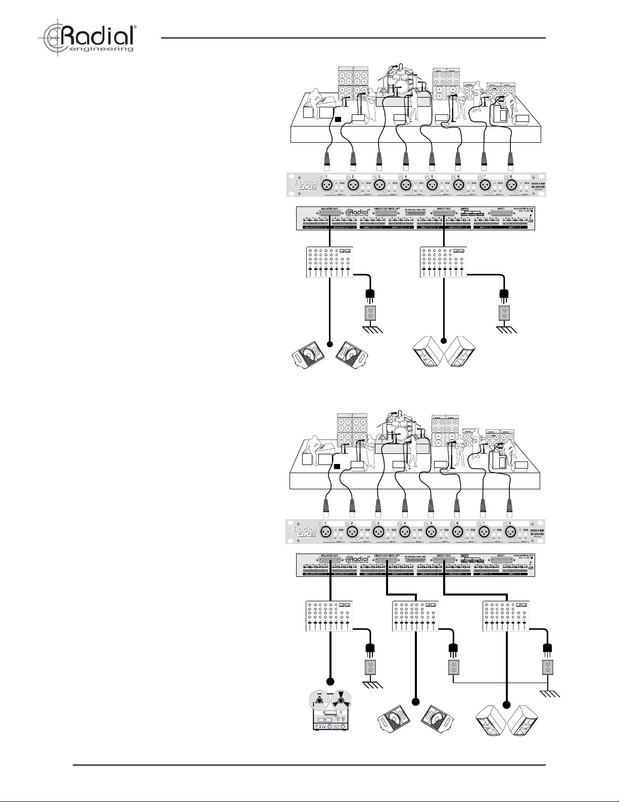
Connecting Two Mixing Consoles
This is the most basic OX8 set up and allows the
MAIN PA and MONITOR consoles to have access to the stage microphone signals.
The MAIN PA console connects to the DIRECT
output and supplies 48V phantom power to the
mics and active direct boxes.
The MONITOR console uses the ISOLATED output and is therefore electrically decoupled from
the rst console. The MONITOR console may be
powered from a separate AC-mains circuit without creating ground loops.
True to the Music
Connecting Three Mixing Consoles
This advanced setup connects three consoles to
an OX8.
The MAIN PA console connects to the DIRECT
output and the MONITOR console to the auxiliary DIRECT with LIFT output. In order to avoid
hum and buzz from ground loops these consoles
should be powered from the same AC main circuit or a power distribution system designed to
prevent ground loops from forming.
A third RECORDING console connects to the isolated output and is therefore electrically decoupled from the MAIN PA and MONITOR consoles.
The RECORDING console may be powered from
a separate AC mains circuit without creating
ground loops.
Monitors
Isolated Output
AC Mains
Circuit 2
Main PA
Direct Output
EarthEarth
AC Mains
Circuit 1
6
Radial Engineering Ltd.
Recorder
Isolated Output
Earth
AC Mains
Circuit 2
Direct with Lift
Monitors
AC Mains
Circuit 1
AC Mains
Circuit 1
Main PA
Direct Output
™
User Guide
OX8
Earth
Page 9

True to the Music
INTERNAL GROUNDING OPTIONS
The Radial OX8 features two internal grounding options
that will be of interest to system engineers when integrating
the OX8 into complex audio-visual systems. Most users will
not need these options and can accept the factory default
settings.
Internal Ground Lift - Each Channel
Each channel’s transformer features an internal ground
switch that re-connects the ground around the transformer.
It may be used on a per-channel basis to accommodate
specic grounding needs. For example, it may be necessary to set this switch to closed for devices that have a
oating ground, like battery powered laptop computers or
devices powered with an AC to DC adaptor.
By default this switch is set to open, or lifted (out position)
so the transformer can decouple equipment connected to
the ISOLATED outputs. Pushing the switch in (closed) will
connect the input ground to the output ground at the ISOLATED output for that channel.
Internal Chassis Ground Lift - All Channels
All connectors are 100% isolated from the steel chassis
allowing chassis and signal ground to be kept separate.
However, a single internal switch is provided to connect
the pin-1 cable shields to the chassis without modifying the
OX8. By default, this switch is factory set to open or “lifted”
allowing the chassis to “oat” ungrounded.
Each channel has a lift switch
directly below the transformer.
Should a specic grounding scheme require the cable
shields to be bonded to the chassis simply set this switch
to closed (pushed in position). The switch may be accessed
through a small hole in the side of the steel chassis or by
removing the top cover. The chassis ground switch does
not effect the isolation provided by the transformer at the
ISOLATED output.
On the rear panel a ground screw provides a convenient
point to bond the chassis. Use a heavy gauge solid copper
wire to bond the OX8 chassis to your technical ground.
Access the internal chassis ground
lift switch through a small hole
in the side of the chassis.
Rear panel chassis screw used
for bonding to technical ground.
Radial Engineering Ltd. OX8™ User Guide
7
Page 10

True to the Music
FAQ
Can I use the Radial OX8 to split line level signals?
You can use the Radial OX8 to accept line level signals by depressing the -35dB input PAD. The output will however be mic level as
this is the norm with mic splitters. If you want to split line levels, the LX8 may be a better choice.
Can I use several OX8 splitters together instead of buying a snake system like the Radial V12™?
Yes. There does however come a point where the convenience of a full sized concert snake probably makes more sense. This really
is a matter of choice and convenience. Ask the Radial custom shop for a quote if you need a larger format splitter.
What is the difference between the various Eclipse and Jensen transformer options?
Eclipse offers a wider range of transformers in order to meet several price and performance points. The Eclipse MS10™ is our most
popular mic splitter transformer. It provides exceptional performance from 20Hz to 20kHz while the Jensen has an extend frequency
response from 10Hz to 40kHz.
Why did Radial use D-Sub connectors on the OX8?
Back in the 90’s, Tascam began using D-Subs on their DA88 digital recorders and they quickly became one of the most popular connectors for digital recording formats on the planet. Since they are very high density, you can really pack in a lot of channels in a small
place. This makes them a good choice for the OX8.
Can I order a Radial OX8 with two isolated outputs?
No. To get two isolated outputs, you would need to assemble eight JS3™ and mount them into a J-Rack™. This would give you eight
isolated outs in two rack spaces.
How does the Radial OX8 compare to the Radial LX8?
The OX8 is designed for mic signals (-40dB typical) while the LX8™ is designed for line levels (+4dB typical). These employ different
types of transformers to handle the different levels.
Does the OX8 need power to make it work?
No. The OX8 is completely passive. Simply plug in and play.
What is the difference between Radial mic splitters and others?
Top professionals specify Radial because they depend on a product that is durable and will not fail. Radial uses the very best components to ensure fail-safe use. Others can save you money by being cheaper, but will likely not deliver the same level of quality or
performance. Check the specs. If they are not complete, then you will likely end up being surprised.
Can I have an XLR panel made to go along with some OX8s?
Yes. Contact the Radial Custom Shop and they can put a quote together for you.
What is the difference between an active splitter and a passive one?
An active splitter is a multi-channel preamplier or buffer that electronically amplies the signal while a passive splitter does not amplify
the signal at all; it uses special transformers to do the task. Most pros prefer a passive splitter as it taps the signal directly from the mic
allowing each mix position to set the gain stage most appropriate to the individual’s need.
Will phantom power hurt the OX8?
No. The OX8 is designed to work with phantom power by allowing it to ow through the OX8’s direct output back to the microphone
inputs. The isolated outputs will simply block phantom power if present.
Why can’t I simply split a signal without a transformer?
You can. But you will be subject to noise caused by stray DC voltage. Transformer isolation really helps to eliminate hum and buzz
which can turn a great performance into an unusable recording.
Radial Engineering Ltd.
OX8
™
User Guide
Page 11

True to the Music
SPECIFICATIONS
Specications OX8-Jensen OX8-Radial
Audio Circuit Type: Passive transformer based mic level splitter
Number of Channels: 8 channel 3-way splitter (1-in/3-out)
Frequency Response: 20Hz ~ 20KHz (+0dB/-0.2dB) 20Hz ~ 18KHz (+0dB/-3dB)
Dynamic Range: 140dB 140dB
Maximum Input: +2dBu @ 20Hz +2dBu @ 20Hz
THD +Noise: 0.003% @ 1kHz 0.005% @ 1kHz
Phase Deviation: 0.7° @ 100Hz; 2.8° @ 20Hz 1° @ 100Hz; 5° @ 20Hz
CMRR: -115dB @ 60Hz 114dB @ 60Hz
Input Impedance: 150 Ohms, balanced
Output Impedance: 150 Ohms, balanced
Features
Transformer: JT-MB-CPC, 1:1 ratio Eclipse MS10, 1:1 ratio
Shield: Dual Faraday, MuMETAL® can
Input Pad: -36dB (allows line-level sources)
Ground Lift: Disconnects XLR pin-1 at direct-2 and isolated output
XLR Conguration: AES standard (pin-2 hot)
DB-25 Conguration: Tascam analog audio standard
General
Construction: 14 gauge steel
Finish: Durable powder coat
Size (L x W x H): 19” x 6” x 1.75” (48.25cm x 15.25cm x 4.45cm)
Weight: 7.5lb (3.4 kg)
Shipping Size (L x W x H): 22” x 10.375” x 4.5” (55.9cm x 26.4cm x 11.4cm)
Shipping Weight: 8lb (3.63kg)
Power: Passive, no power required
Conditions: For use in dry locations only between 5°C and 40°C
Warranty: Radial 3-year, transferable
Specications are subject to change without notice
Radial Engineering Ltd. OX8™ User Guide
Page 12

RADIAL ENGINEERING LTD.
3 YEAR TRANSFERABLE WARRANTY
RADIAL ENGINEERING LTD. (“Radial”) warrants this product to be free from defects in material and
workmanship and will remedy any such defects free of charge according to the terms of this warranty.
Radial will repair or replace (at its option) any defective component(s) of this product (excluding nish
and wear and tear on components under normal use) for a period of three (3) years from the original
date of purchase. In the event that a particular product is no longer available, Radial reserves the
right to replace the product with a similar product of equal or greater value. To make a request or
claim under this limited warranty, the product must be returned prepaid in the original shipping container (or equivalent) to Radial or to an authorized Radial repair center and you must assume the risk
of loss or damage. A copy of the original invoice showing date of purchase and the dealer name must
accompany any request for work to be performed under this limited warranty. This limited warranty
shall not apply if the product has been damaged due to abuse, misuse, misapplication, accident or as
a result of service or modication by any other than an authorized Radial repair center.
THERE ARE NO EXPRESSED WARRANTIES OTHER THAN THOSE ON THE FACE HEREOF
AND DESCRIBED ABOVE. NO WARRANTIES WHETHER EXPRESSED OR IMPLIED, INCLUDING BUT NOT LIMITED TO, ANY IMPLIED WARRANTIES OF MERCHANTABILITY OR FITNESS
FOR A PARTICULAR PURPOSE SHALL EXTEND BEYOND THE RESPECTIVE WARRANTY
PERIOD DESCRIBED ABOVE OF THREE YEARS. RADIAL SHALL NOT BE RESPONSIBLE OR
LIABLE FOR ANY SPECIAL, INCIDENTAL OR CONSEQUENTIAL DAMAGES OR LOSS ARISING
FROM THE USE OF THIS PRODUCT. THIS WARRANTY GIVES YOU SPECIFIC LEGAL RIGHTS,
AND YOU MAY ALSO HAVE OTHER RIGHTS, WHICH MAY VARY DEPENDING ON WHERE YOU
LIVE AND WHERE THE PRODUCT WAS PURCHASED.
www.radialeng.com
Radial Engineering Ltd.
1588 Kebet Way, Port Coquitlam BC V3C 5M5
tel: 604-942-1001 • fax: 604-942-1010
email: info@radialeng.com • web: www.radialeng.com
Radial OX8 user guide - Part #R870 1185 / V2 / 03-2017
Specications and appearance are subject to change without notice.
© Copyright 2017, all rights reserved.
 Loading...