

Page 1

JX44 AIR CONTROL
Guitar and Amp Distribution Switcher
True to the Music
Order No. JX44: R800 6500
Radial Engineering Ltd.
www.radialeng.com
1588 Kebet Way, Port Coquitlam BC V3C 5M5
tel: 604-942-1001 • fax: 604-942-1010
email: info@radialeng.com • web: www.radialeng.com
Specifi cations and appearance are subject to change without notice.
Copyright © 2009 Radial Engineering Ltd.
Order No. SGI-44: R800 6700
Order No. JR5: R800 6600
OWNER’S MANUAL
www.radialeng.com
Page 2

Radial JX44 Air Control Owner’s Manual
Guitar and Amp Distribution Switcher
Table of Contents .......................................................Page
PART 1: GETTING TO KNOW THE JX44
Seven Section Breakdown ......................................................................1
Feature Set Overview ..............................................................................2
Front Panel Features and Functions .......................................................3
Rear Panel Features and Functions ........................................................5
PART 2: USING THE JX44
Setting Up Inputs and Guitars .................................................................8
Setting Up Outputs and Amps .................................................................9
PART 3: PROGRAMMING BANKS
Programing The JX44 ..............................................................................10
Programming The JR5 Remote Footswitch .............................................11
PART 4: USING THE ADVANCED FEATURES
EFX Local Effects Loop ...........................................................................12
SGI-44 Long Haul Effects Loop ...............................................................14
Direct Out ................................................................................................16
X-AMP .....................................................................................................17
FAQ & Trouble Shooting Guide ...............................................................18
Signal Flow Block Diagram .....................................................................19
Specifi cations ..........................................................................................19
User’s Notes ............................................................................................20
Warranty .................................................................................................. Back Cover
Electrical Shock Caution Statement ........................................................ Back Cover
INTRODUCTION
Congratulations on your purchase of the Radial JX44 Air Control!
The Radial JX44 is a professional 19” rack device designed primarily for guitarists to manage their live rigs when touring. It has
4 inputs for guitars and 4 outputs to drive multiple amplifi ers. In between the inputs and outputs, facilities have been added to
help manage pedals, rack effects and tuning. The JX44 can be used on its own or be equipped with the optional Radial JR5
remote footswitch to choose guitars, select amplifi ers and control effects.
After the tour, you may want to touch up a few notes in post production. To this end the JX44 has been equipped with a built-in
Radial ProDI direct box and a Radial X-Amp. The direct box lets you record a dry guitar track during the tour. The X-AMP lets
you re-amplify your performances afterwards and send the signal back out to pedals and amps to recreate the sounds you need
for the live album.
With all of this stuff going on, one would think that using the JX44 is diffi cult. Well, in fact we invested a bunch of time and energy
to make sure a seasoned professional could actually get up and running with the JX44 without even needing a manual! In fact,
we even silk screened the programming instructions on the top panel. But as with any good product, a good manual should both
guide the user towards a deeper understanding of the product and inspire creative applications. So, put the manual next to your
bunk on the bus and read it! We know the JX44 will spark your imagination!
Should you have any questions, comments or concerns not covered in these pages, please visit our web site and the JX44 FAQ
section. This is where we post the latest details and applications. If you do not fi nd what you need there; feel free to send us
an email at info@radialeng.com and we will do our best to answer you as quickly as possible. Strap yourself in and get ready
for lift off. Enjoy!
Radial Engineering Ltd.
1588 Kebet Way, Port Coquitlam BC V3C 5M5
tel: 604-942-1001 • fax: 604-942-1010
email: info@radialeng.com • web: www.radialeng.com
Specifi cations and appearance are subject to change without notice.
Copyright © 2009 Radial Engineering Ltd.
www.radialeng.com
Page 3
True to the Music
PART 1: GETTING TO KNOW THE JX44
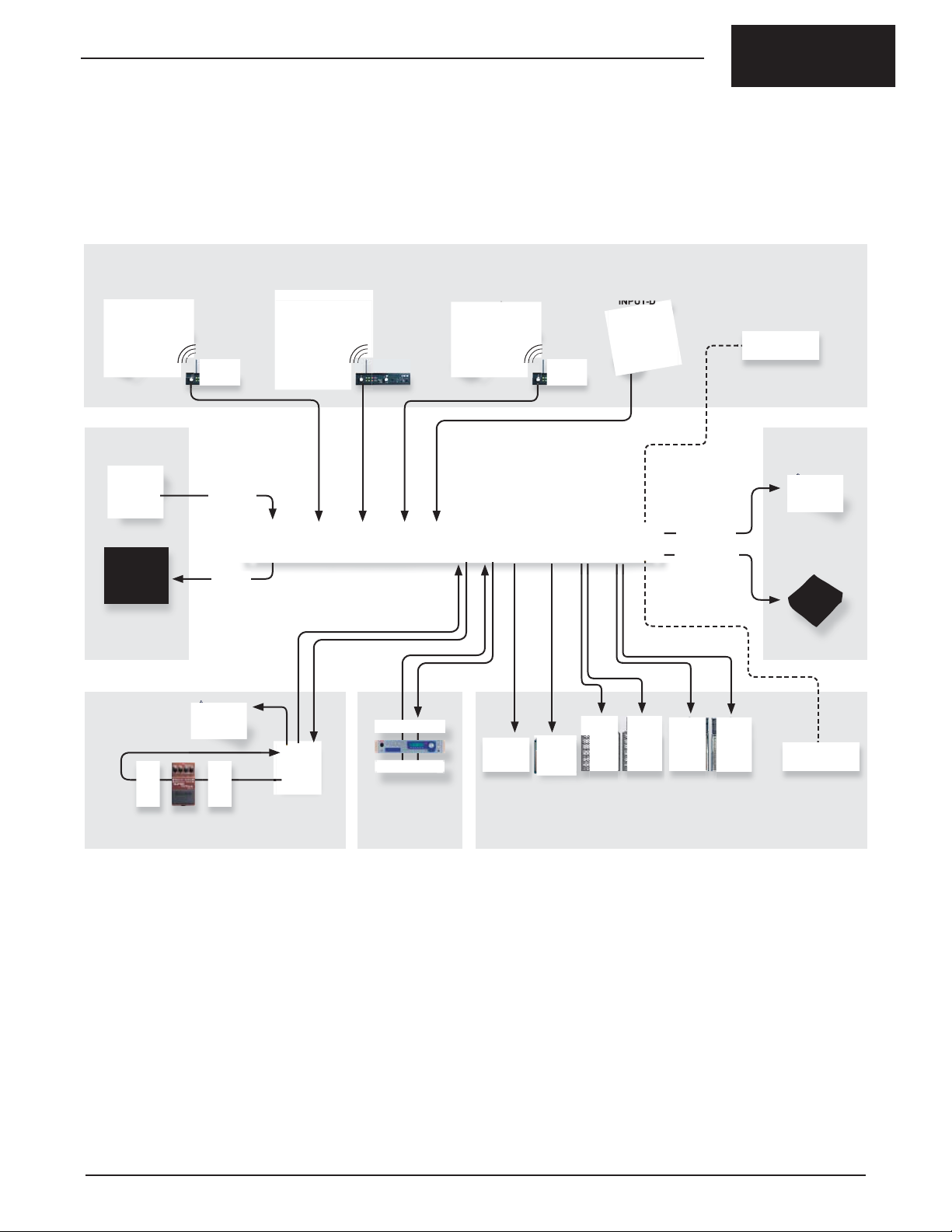
The JX44 is an amalgamation of guitar oriented devices combined into one product. It is designed to streamline the processes used in live
touring and studio recording. The basic functions give you the ability to control complex live guitar setups. The advanced features go beyond that
and allow the JX44 to seamlessly integrate into today’s highly technical concert productions. The JX44 can be broken down into seven distinct
sections:
1. INSTRUMENT INPUTS
INPUT-A INPUT-B INPUT-C INPUT-D
Wireless Wireless Wireless
7. X-AMP
X-AMP IN
Recorder
DI OUT
Mixer
6. DIRECT
Remote
Tuner
TUNER OUT
FOOTSWITCH
GUITAR SELECT
5. TUNER
Local
Tuner
Generic
Footswitch
MUTE FS
4. SGI-44 LOOP
3. EFX LOOP
1. INSTRUMENT INPUTS: The JX44 starts with a four input
instrument selector for wired and wireless guitars. The JX44 can
have all your instruments ready and waiting and the optional JR5
remote footswitch allows hands free operation with big, bright LED
indicators that are easy to see on stage.
2. AMPLIFIER OUTPUTS: These four outputs can connect up to
six amplifi ers giving you an incredibly fl exible multi-amp rig. You
can manually select amps or program a bank to recall a group of
amps with the front panel controls or JR5 footswitch. A pristine
Class-A signal path and transformer isolation offer amazing Radial
quality sound with immunity from hum and buzz caused by ground
loops.
3. EFX LOOP: Patch rackmount effects and pedals into this local
hi-impedance effects loop and all your instruments can use them.
The local effect loop can be assigned to each amplifi er output.
OUT-1 OUT-2 OUT-3 A & B OUT-4 A & B
2. AMPLIFIER OUTPUTS
4. SGI-44 LOOP: This balanced long-haul effects loop works with
the optional SGI-44 to connect a pedalboard up to 100 meters
(300 feet) away from your amps without introducing noise or signal
loss.
5. TUNE & MUTE: The JX44, JR5 and SGI-44 offers tremendous
tuning and mute options: You can connect a rack and pedalboard
tuner plus mute the guitar from fi ve different places.
6. DIRECT OUTPUT : The built in Radial ProDI direct box has many
uses on-stage and in the studio. This one has been optimized with
features for the guitarist like pre/post effects loop and assignment
to one or all instrument inputs.
7. X-AMP INPUT : The JX44 lets you tap into the huge tone shaping
and post production possibilities of re-amping. The X-AMP lets you
send guitar tracks from your multi-track to the JX44 and route the
signal to your effects and amps for re-recording.
AMP SELECT
Radial Engineering Ltd. JX44 Owner’s Manual
1
Page 4
True to the Music
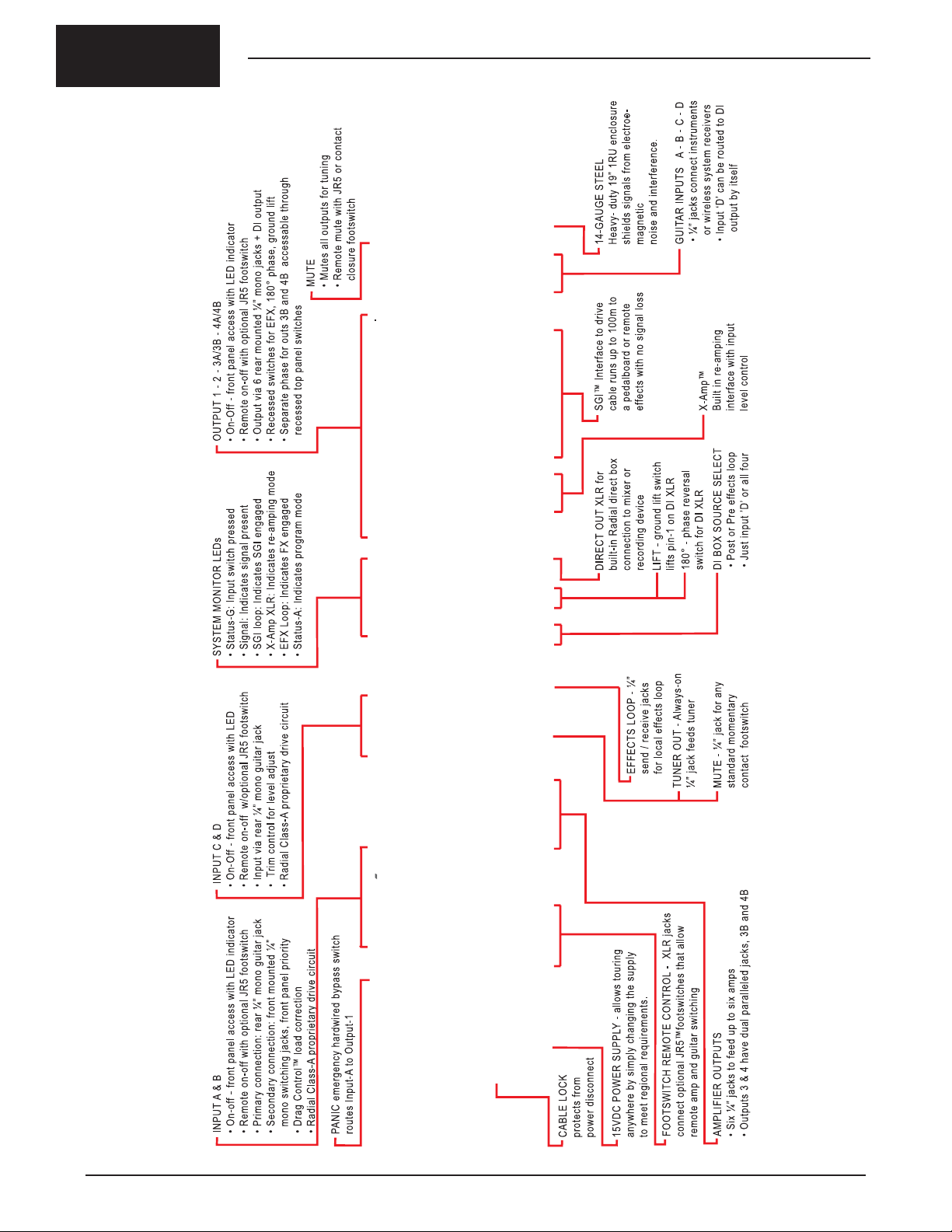
FEATURE SET OVERVIEW
2
Radial Engineering Ltd.
JX44 Owner’s Manual
Page 5
True to the Music
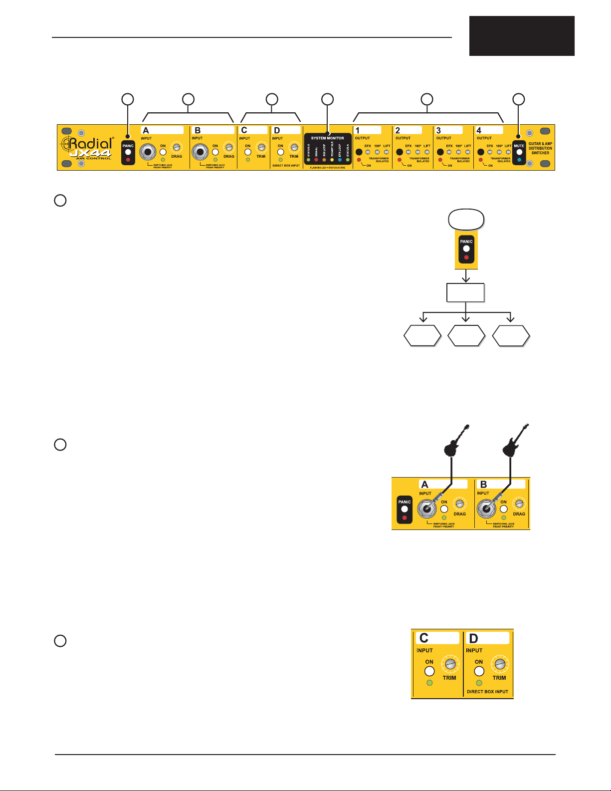
FRONT PANEL FEATURE SET
A B D E FC
A
PANIC BUTTON
In the event of a problem such as a wireless system failure, the PANIC button
activates a hardwire bypass and automatically connects INPUT-A directly to
OUTPUT-1. The SGI and local EFX LOOP are also bypassed. The LED fl ashes
to indicate panic mode is active. Release the PANIC button to revert to normal
operation. (Fig.1)
If power is disconnected, the JX44 will automatically revert to PANIC mode and
engage the hardwire connection. This allows you to continue playing through your
fi rst amp while the technical problems are sorted out and power is restored.
Depress
Panic Button
JX44 Enters
Panic Mode
INSTRUMENT INPUTS
The JX44 is equipped with four guitar inputs. These employ Radial’s proprietary
Class-A drive circuit for the best sound and lowest noise. Selecting an input is done
by depressing the front panel ON switch for the desired instrument, or remotely
with the optional JR5 footswitch. Each input has an LED on the front panel that
illuminates when selected.
The JX44’s inputs are ‘exclusive’ whereby only one can be on at a time. This
‘safety feature’ prevents noise from inactive guitars entering the system. An input
can be muted by depressing the ON switch a second time. To restore the input
depress the ON switch again or select a different instrument.
B
INPUT-A & B
Although instruments are usually connected at the rear jacks INPUTS-A and B are
equipped with switching jacks on the front panel. These will override the rear panel
jacks when a cable is inserted. This makes the front jacks a handy place to quickly
fl y in a new instrument while another is connected through the rear jacks. (Fig.2)
We added DRAG™ control on inputs A and B for the purists who want to connect to
their amps with a ‘real cable’ in the most transparent way possible. DRAG is a load
correction function that allows you to reintroduce the natural loading characteristic
of a direct cable connection to your amp.
Here’s how it works. When you connect your guitar directly to your amp, the
amplifi er ‘sees’ your pickups as a load. When a buffer like the one inside the JX44
or built into a wireless system is introduced, your amplifi er no longer ‘sees’ your
pickups as a load. Your amp sees the electronically ‘perfect’ output of the JX44.
But sometimes, perfect may not sound quite right. With one simple control, DRAG
allows you to dial-in the natural loading and tone as if your guitar were connected
directly to the amp.
Input-A
Hard wired to
output-1
Fig.1 - In Panic Mode, the tech can grab a guitar
hand it to the artist, connect it to input-A
and the show goes on.
Fig.2 - INPUTS-A and B on the front panel have
priority. When you connect a guitar they will
override the rear inputs.
All other
outputs
are muted
EFX & SGI
Loops are
bypassed
C
INPUT-C & D
Instrument connections for INPUT-C and D are made at the rear jacks. These
inputs are equipped with a recessed TRIM control making them ideal for wireless
systems and active instruments such as acoustic-electrics and guitars with active
pickups (i.e. EMG pickup). The Trim controls let you reduce the level from louder
instruments to better balance with passive instruments connected to the other
inputs. (Fig.3)
INPUT-D is unique in that it may be exclusively assigned to the direct box output.
This is invoked through the direct box controls on the rear panel. See the direct box
Fig.3 - Inputs C and D feature TRIM controls to
balance the levels of louder instrument signals
such as buffered wireless systems and active
acoustic guitars with passive instruments.
section for more information on using this feature.
Radial Engineering Ltd. JX44 Owner’s Manual
3
Page 6

D
SYSTEM MONITOR
At the center of the front panel you will fi nd the SYSTEM MONITOR where six
LEDs display the status of several JX44 functions. (Fig.4)
True to the Music
• STATUS-G This will fl ash every six seconds as the internal microprocessor
checks the status of the input routing and does a self-diagnostic
test. This LED will briefl y fl ash when an input is selected to confi rm
the command.
• SIGNAL This level meter fl ashes when a guitar signal is present at the
input. This is the fi rst place to look when trouble shooting to ensure
the JX44 is receiving a signal from your guitar.
• SGI LOOP Illuminates when the SGI effects loop is active. When active the
SGI loop must be connected or the guitar signal will be interrupted
and no sound will be output.
• X-AMP Illuminates when the re-amping interface is active. When active
the JX44 accepts balanced line signals at the SGI RX rear panel
input.
• EFX LOOP This LED indicates when the effects loop is active. It illuminates
when an amplifi er output assigned to the effects loop is turned on.
• STATUS-A This will also fl ash every six seconds as the JX44 checks the
status of the output routing and does a self-diagnostic test. This
LED stays illuminated when BANK mode is active.
E
AMPLIFIER OUTPUT CONTROLS
Amplifi er output connections are made at the rear panel jacks. (Fig.5a) The four
amplifi er outputs are selected using the front panel ON buttons or remotely with
the JR5 footswitch. An LED illuminates when the output is selected. While the
instrument inputs on the JX44 are ‘exclusive’ (only one at a time), the amplifi er
outputs are ‘inclusive’ whereby you can activate as many amps as you like.
Fig.4 - The JX44 System Monitor provides the status of six
functions with easy to see LED indicators.
Fig.5a- To keep the front panel clear from obstructions,
all amplifi er connections are done on the rear.
Amplifi er outputs 1 and 2 are single while outputs
3 and 4 are dual.
Amplifi er outputs can be selected manually or programmed and saved as a bank.
This way different combinations of amps can be recalled with a single button or
footswitch. Amplifi er outputs are transformer isolated to eliminate ground loops
and equipped with three recessed controls that help set up your amps for the best
sound and least noise. (Fig.5b)
• EFX Assigns an amplifi er output to the effects loop bus.
• 180° Polarity reverse switch is used to set the absolute phase between
multiple amps.
• LIFT Isolates the ground connection to reduce hum and buzz caused by
ground loops.
F
MUTE FUNCTION (FRONT PANEL)
The front panel MUTE switch is a multi function control. Its primary function is to
mute the amplifi er outputs to facilitate silent tuning. When the JX44 is muted, all
outputs are silenced and effects loops turned off. The only output to remain active
will be to the tuner (Fig.6).
The MUTE LED indicator illuminates when the function is active. The MUTE control
is also used to access and program BANKS as described later in this manual.
Fig.5b- Separate EFX, 180° and ground LIFT controls on each
output allow you to optimize the performance of your
amps and system setup.
Depress
Mute Button
JX44 Enters
Mute Mode
Outputs
1 thru 4
are muted
Fig.6 - MUTE mode, all outputs are silenced
except the tuner output.
Direct Out
is muted
Tuner out
remains
active
4
Radial Engineering Ltd.
JX44 Owner’s Manual
Page 7
True to the Music
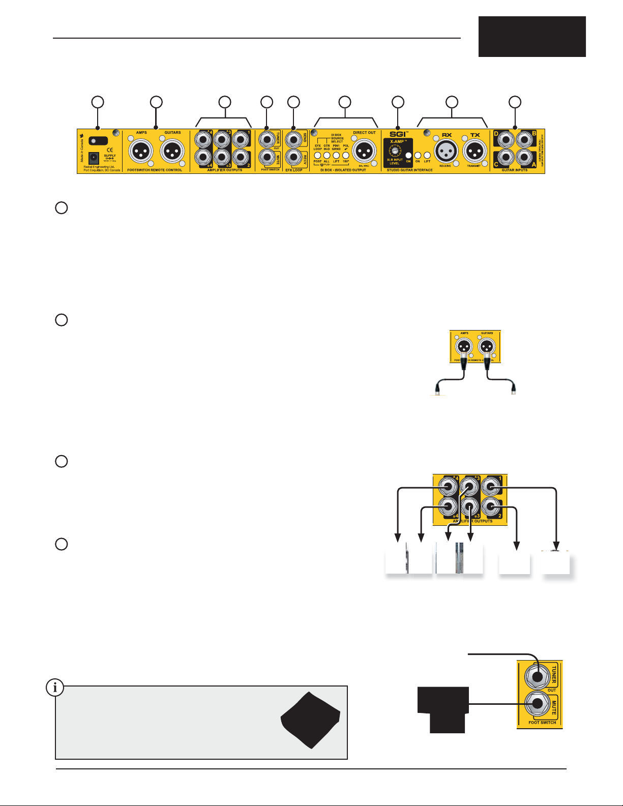
REAR PANEL FEATURE SET
G H I J K L M N O
G
POWER CONNECTION
The Radial JX44 is powered by a Radial 15 volt DC external power supply. Two
power supplies are packed in the shipping box. The second power supply is
provided as a spare in case the fi rst is lost or damaged. Do not substitute with
another type.
The power connection on the rear panel features a cable clamp to prevent
accidental disconnect. To use the cable clamp loosen the hex screw, loop the
power supply cable through and tighten. (Fig.7)
H
FOOTSWITCH REMOTE CONTROL PORTS
There are two remote control ports on the rear panel for connecting the Radial JR5
remote footswitch. One port is used for controlling the instrument inputs and the
other for amplifi er outputs. Standard XLR mic cables are used to connect between
the JR5 and the JX44 (Fig.8).
Fig.7 - A handy cable clamp prevents
accidental power disconnection.
Once connected the microprocessor will recognize and auto-confi gure the JR5
footswitch. When the JR5 is connected to the GUITARS port it can select and
GUITARSAMPS
mute the active instrument input. When connected to the AMP port the JR5 selects
amplifi er outputs and can mute the system for tuning. The LED indicators on the
JR5 will coincide with the JX44 front panel indicators giving the performer and tech
the same visual cues.
I
AMPLIFIER OUTPUT JACKS
Fig.8 - Two Radial JR5 footswitches may be used at once: one to
control guitars and another to control the amps.
The JX44 has six ¼” amplifi er output jacks on the rear panel. Amplifi er OUTPUT-1
and 2 use a single jack while OUTPUT-3 and 4 feature dual jacks labeled 3A/3B
and 4A/4B. These dual outputs allow you to connect two amps to OUTPUT-3 and
4 (Fig.9). All amplifi er outputs are transformer isolated to eliminate hum and buzz
caused by ground loops.
J
TUNER OUT AND MUTE FOOTSWITCH JACK
Connecting an electronic tuner is done via the TUNER output jack on the rear
panel. This buffered output is always on and connecting your tuner here will
remove it from the main signal chain preventing clock noise from bleeding into
your guitar signal. (Fig.10)
Fig.9 - There are four amplifi er outputs on the JX44. Amplifi er
outputs 1 & 2 are single jacks while outputs 3 & 4 are dual.
Below the TUNER out you will fi nd the MUTE footswitch jack. This is used to
remotely MUTE the JX44. When muted, all outputs will be turned off except
the tuner out. Any standard footswitch wired as a normally open, non-latching
momentary switch with a ¼” mono plug may be used. When the remote footswitch
is depressed, the front panel MUTE LED will illuminate indicating the MUTE
Electronic Tuner
function is active. Either the front panel control or remote footswitch can be used
to toggle the mute function.
Non-latching footswitch
The BigShot SW2 is a two channel universal remote
footswitch that can be used with the JX44 to engage
the mute function. Because the SW2 supports both
latching and momentary switching you can use the
second footswitch to switch amplifi er channels or
effects. See www.radialeng.com for more info.
Fig.10 - A separate tuner output keeps clocking noise out of the
signal path. The MUTE jack uses a non-latching momentary
footswitch.
Radial Engineering Ltd. JX44 Owner’s Manual
5
Page 8

K
EFX LOOP - LOCAL EFFECTS LOOP
The EFX LOOP is a buffered effects loop
for pedals and rackmount processors
that accepts instrument level signals.
Connections are made at the ¼” SEND
and RECV (receive) jacks on the rear panel
(Fig.11a). Amplifi er outputs share the effects
loop bus (Fig.11b) and are assigned using
the recessed EFX switches on the front
panel (Fig.11c).
True to the Music
Fig. 11b: The effects loop feeds a bus that the amplifi er outputs share.
L
DIRECT OUT
Fig.11a - The EFX LOOP uses the SEND and
RECV jacks on the rear panel.
Fig. 11c: The loop is activated by using the recessed EFX switch for each amplifi er output on the front panel.
The JX44 is equipped with a balanced 600 Ohm mic-level DI output. It combines
Radial’s award winning Class-A drive circuitry with our transformer isolated ProDI
direct box to deliver great sound and immunity to ground loops. The DIRECT OUT
section incorporates several functions (Fig.12).
• POL 0º/180º This 180º polarity reverse switch is used to correct phase or help
reduce feedback on stage with acoustic guitars.
• GRND/LIFT This ground lift switch isolates pin-1 on the DIRECT OUT XLR to
reduce buzz and hum caused by ground loops.
• GTR IN-D This switch selects which inputs will be sent to the DIRECT output.
When set to the inward position all inputs are routed to the DIRECT
out. In the outward position INPUT-D is sent to the DIRECT out and
the other three inputs (A, B & C) are excluded.
• EFX LOOP This switch assigns the DIRECT output either “pre” or “post” effects
loop. When set to the outward position the signal is tapped before
the effects loop and the DIRECT out is pre-effects (dry). The inward
switch position will tap the signal after the effects loop and the
DIRECT out will be post-effects (wet).
M
X-AMP INTERFACE
The Radial X-AMP is a re-amping interface that allows a pre-recorded track to drive
your amps and effects. For instance you can record a clean track with the DIRECT
out and play it back through the JX44’s X-AMP input to recreate your stage sound
and fi x a bum note. It can also be used to replace a complete track and create a new
sound in post production. The X-AMP section includes several controls (Fig.13).
Fig.12 - The JX44 is equipped with a DI box that can be
assigned to all guitars for re-amping or routed
from INPUT-D for an acoustic guitar.
• ON This switch turns the X-AMP interface on and illuminates the LED in
the SYSTEM MONITOR. When active the RX XLR input accepts a
+4dB balanced line-level signal.
• LEVEL The X-AMP input level control is used to attenuate line level signals
to match the level from your guitar.
• RX XLR-F To save space the X-AMP shares this jack with the SGI feature.
When the X-AMP is active the RX jack receives a balanced line-level
signal and converts it to guitar level.
• LIFT This ground lift switch isolates pin-1 on the RX XLR input to reduce
buzz and hum caused by ground loops. This control is shared
between the SGI and X-AMP.
6
Radial Engineering Ltd.
Fig.13 - Play a clean track through the JX44 and drive
pedals and amplifi ers to create new sounds.
JX44 Owner’s Manual
Page 9
True to the Music
N
SGI LONG-HAUL EFFECTS LOOP
Running unbalanced guitar cables long distances can add severe noise while
negatively affecting the tone. This is particularly acute on large stages when
sending high impedance guitar signals from the backline where the amps and
wireless are to a pedalboard and back again to the amps. To solve the problem,
the JX44 comes equipped with a “long-haul” effects loop called SGI.
The Radial SGI is a proprietary balanced low impedance audio interface. It uses
standard XLR mic cables to send and receive the guitar signal over long distances
up to 100 meters (300 feet) using the optional Radial SGI-44 located at the
pedalboard.
The SGI inside the JX44 transmits a balanced signal to the SGI-44 where it is
converted to hi-impedance for the effects on the pedalboard. The hi-Z signal from
the effect pedals is sent back through the SGI-44 for the return trip to the JX44,
completing the loop. (Fig.14). The SGI section includes several controls.
• ON This switch turns the SGI interface on and illuminates the LED in
the SYSTEM MONITOR. The SGI loop must be completed or no
sound will be heard.
• LIFT This ground lift switch isolates pin-1 on the RX XLR input to reduce
buzz and hum caused by ground loops.
• TX XLR-M Balanced, low impedance XLR output transmits the guitar signal to
the SGI-44 pedalboard interface.
• RX XLR-F Balanced, low impedance XLR input receives the guitar signal
from the SGI-44 pedalboard interface. The SGI is transformer
isolated to eliminate hum and buzz caused by ground loops. The
RX connector is shared with the X-AMP interface to save space.
O
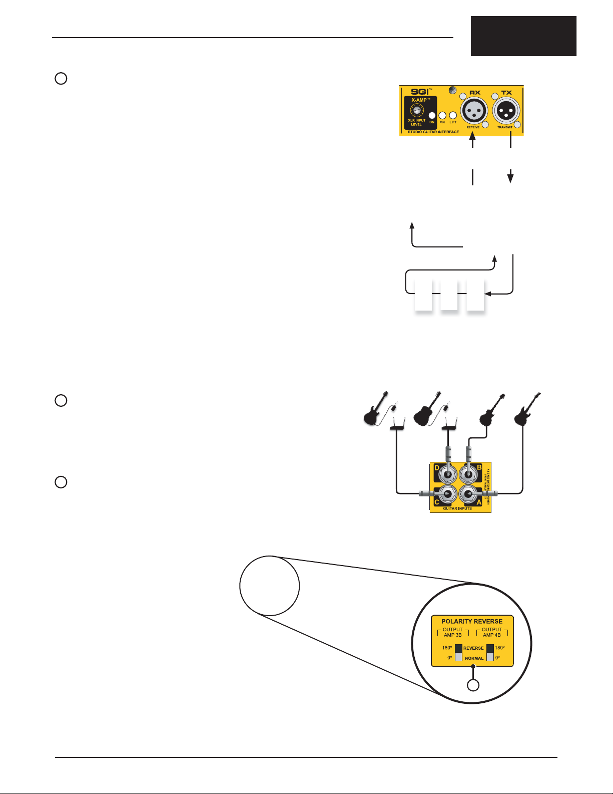
INSTRUMENT INPUTS
Four 1/4” input jacks receive signals from the instruments and wireless systems.
Connections are located on the rear panel to keep the front panel unobstructed
during hectic shows (Fig.15).
XLR Mic Cables
Up to 100 meters
Fig.14 - SGI LOOP fl ows out to the SGI-44, through
pedal effects, and back to the JX44.
Note: INPUT-A and B feature front panel jacks that override the rear inputs.
P
TOP PANEL POLARITY CONTROLS
While the polarity reverse controls for OUTPUT-3A and 4A are located on the front
panel, due to limited space, the “B” output polarity switches are found on the top
panel. (Fig.16).
Fig.15 - Primary input connections on the rear panel.
P
Fig.16 - Polarity controls for OUTPUTS-3B and 4B.
Radial Engineering Ltd. JX44 Owner’s Manual
7
Page 10

PART 2: USING THE JX44
SYSTEM MONITOR
STATUS-G
EFX LOOP
SGI LOOP
REAMP XLR
STATUS-A
SIGNAL
True to the Music
The best way to approach the JX44 is by connecting and testing all your guitar
inputs fi rst before proceeding to the amplifi ers. Once the guitars are working we
will discuss how to set up the amps for the least noise and proper phase alignment.
With the amps ready we will then cover programming the JX44’s outputs to create
banks and store them to memory. Finally, we will add effects, discuss applications
such as re-amping and look at options for using the DI output.
POWERING UP
Go ahead and plug in the power supply before connecting anything else. Once the
power has been connected, the JX44 will immediately power on and automatically
connect INPUT-A to OUTPUT-1. Their LED indicators will illuminate.
Check the SYSTEM MONITOR to ensure the LED indicators for the SGI LOOP
and REAMP XLR (X-AMP) are off. If either of these LEDs are illuminated go to
the SGI section of the rear panel and set their ON switches to the outward (off )
position before continuing (Fig.17).
CONNECTING AND TESTING INPUTS
It’s a good idea to audition each instrument as they are connected. Confi rming
that all four inputs are working properly before connecting multiple amps will make
trouble shooting easier. To test the inputs we are going to need an amplifi er.
CAUTION: POTENTIAL FOR ELECTRIC SHOCK HAZARD
Please read the caution statement at the end of this manual
before connecting any amplifi ers to the JX44.
TM
SGI
TM
X-AMP
XLR INPUT
ON
ON
LEVEL
STUDIO GUITAR INTERFACE
Fig.17 - LED for SGI and REAMP XLR (X-AMP) must
be off. Their controls are on the rear panel.
Fig.18 - Connect an amplifi er to OUTPUT-
1 to test the instrument inputs.
LIFT
RX
RECEIVE
Connect OUTPUT-1 to your test amp. (Fig.18) The LED indicator for OUTPUT-1
should already be illuminated. If not, depress the ON switch to make it active. Turn
your amp on and set it to a low volume level. As a precaution always test your
system at a low volume to prevent equipment damage.
INPUT-A and B
Instruments with passive pickups are best connected to INPUT-A and B so they
can take advantage of the DRAG control. Plug a guitar into INPUT-A (Fig.19). As
you play, the SIGNAL LED in the SYSTEM MONITOR will fl ash indicating your
signal is present (Fig.20). If the LED is not fl ashing INPUT-A may not be selected.
Depress the ON switch to activate. At this point, you should hear your guitar. Once
your fi rst input is working you are ready to move on to INPUT-B. Plug a guitar into
INPUT-B. Notice that depressing the ON switch for INPUT-B will cause INPUT-A
to turn off.
USING DRAG CONTROL (INPUT-A and B)
If you are connecting a passive instrument to INPUT-A or B with a guitar cable,
as opposed to a wireless system, you might want to adjust the DRAG control at
this time. We have purposely recessed the DRAG control so that once set, it is not
easily changed. Use a guitar pick to make adjustments and start with the DRAG
control turned fully clockwise. At this setting it has no effect on the signal. As you
play, turn the control counter-clockwise in small increments until you fi nd the
‘sweet spot’ that sounds natural to you. (Fig.21)
INPUT-C and D
Instruments with active pickups and wireless systems are best connected to
INPUT-C and D so they can take advantage of the TRIM control. Plug in a guitar
and test these inputs to confi rm they are working.
USING THE TRIM CONTROLS (INPUT-C and D)
Once INPUT-C and D are working you can use the TRIM control to attenuate their
levels to match those of your passive instruments. Switch back and forth between
inputs while adjusting the TRIM controls until all inputs are matched in level.
Once all your inputs are working you can move on to connecting your other
amplifi ers.
Fig.19 - Connect an instrument to INPUT-A.
Fig.20 - This LED indicates when an instrument
signal is present at the active input.
Fig.21 - Use your guitar pick to adjust the DRAG.
8
Radial Engineering Ltd.
JX44 Owner’s Manual
Page 11

True to the Music
CONNECTING AMPLIFIERS
Connect amplifi ers to OUTPUT-2, 3 and 4. Turn your amps on and set each one
at a low volume level for testing. Note that OUTPUT-3 and 4 feature dual jacks to
connect more than one amp if desired (Fig.22).
Start with OUTPUT-1 and listen for hum or buzz. If you hear noise, depress the
recessed LIFT switch on the front panel. Use a tweaker (small screw driver) to
access the recessed controls. In most cases this will reduce hum caused by
ground loops. Continue checking the LIFT switches for the other amplifi er outputs
until all your amps are setup for the least noise (Fig.23).
If you still encounter hum and buzz, check your cables. Second quality cables can
often have poor shielding which can allow noise to enter the system. Test one amp
at a time. For best results limit high impedance cables to a maximum of 20 feet.
If the noise persists have a qualifi ed technician check the amplifi ers to ensure the
safety ground is connected to the amps metal chassis. A loose or missing safety
ground can cause noise and be dangerous.
Amp-1
Amp-2
Connecting electronic devices ahead of and after the JX44 can also form ground
loops causing hum and buzz. To minimize noise it’s a good idea to power all your
amps and effects from one AC outlet using a power bar.
SETTING POLARITY FOR PROPER PHASE
Once all the amps are working it’s very important to ensure your amps are phase
aligned and all loudspeakers are moving in the same direction. Each amplifi er
output is equipped with a recessed 180º polarity reverse switch to help you with
this task (Fig.24). This control inverts the signal polarity at the amplifi er output jack
causing your speakers to move in the opposite direction. Use a tweaker to toggle
the 180º switches.
The best way to proceed is to establish OUTPUT-1 (amp-1) as the ‘phase
reference’. Leave OUTPUT-1 tuned on during the rest of this procedure. For this
test to work properly all your amps should be set at the same volume level so take
a moment to set the level of each amp to match your reference amp.
Start by checking amp-2 with the reference amp-1. Turn on OUTPUT-2 so that
your fi rst and second amps are driving at the same basic volume. While playing
your guitar toggle the recessed 180° polarity switch for OUTPUT-2 and compare
the tone of the two settings. One setting will phase align the two amps. The other
setting will cause amp-2 to be out-of-phase with amp-1. When two amps are ‘inphase’ they reinforce each other and the tone sounds full with good low frequency
content. When two amps are ‘out-of-phase’ they work against each other and their
tone will sound thinner, more hollow and lack bass. Select the setting that produces
the fullest tone. Once set turn OUTPUT-2 off and proceed to the next amp.
Test your amps in the following succession: 1~2; 1~3; 1~4.
If you have more than one amp connected to the dual jacks on OUTPUT-3 and
4, you would still follow this process and afterwards compare 3A to 3B and 4A to
4B while toggling the “B” polarity controls located on the top panel. (Fig.25) When
done, your amps should all be phase aligned.
Amp-3A & 3B Amp-4A & 4B
Fig.22 - Up to six amplifi ers can be connected using the
dual parallel jacks on OUTPUT-3 & 4.
Fig.23 - Hum caused by ground loops can be greatly reduced or
eliminated using the LIFT switch on each amplifi er output..
Fig.24 - Outputs 1, 2, 3A and 4A have their 180° controls on the
front panel.
You may introduce a new polarity problem if you change an amp or add an effect
pedal after setting up the outputs. This may happen because some effect pedals
invert the polarity of the signal and some amps wire their speaker(s) opposite to
others. Take a look at the table below. The signal from OUTPUT-1 and 2 start off
with the same polarity but the OUTPUT-2 signal becomes inverted by an effect
pedal placed after the JX44 amplifi er output. To solve this issue you simply
depress the 180º switch for OUTPUT-2 reversing its polarity. Now when the signal
is inverted by the effect pedal it will match the 0º polarity of OUTPUT-1.
JX44 OUTPUTS EFFECT PEDAL AMPLIFIER SPEAKER DIRECTION
OUTPUT-1
POLARITY
OUTPUT-2
POLARITY
The polarity of output-2 is inverted by an effect pedal causing its amplifi er to push the speaker in an opposite direction. Depressing the 180º switch for output-2 will correct the problem.
+
0º
+
0º
No Pedal Here
-180º
-
Fig.25 - Outputs 3B and 4B have their polarity
controls located on the top panel.
+
0º
-180º
-
Radial Engineering Ltd. JX44 Owner’s Manual
9
Page 12

PART 3: PROGRAMMING BANKS
Up to this point we have been operating the JX44 in MANUAL mode. Although
many players will likely enjoy the “on the fl y” fl exibility of manual mode the JX44
and JR5 also allow the amplifi er outputs to be programmed into four banks. After
the banks are programmed and written to the non-volatile memory they can be
recalled as needed. The major benefi t of BANK mode is quick switching between
multiple amps. For instance, you can transition from a single amp to a multi-amp
setup with a single foot stomp.
It’s important to note that both the JX44 and JR5 have their own on-board memory
where the bank is stored. Banks programmed using the JX44 can only be recalled
by the front panel OUTPUT controls (Fig.26). Banks programmed using the JR5
can only be recalled by the footswitches (Fig.27).
This next section explains how to program and save banks using the JX44. We
will discuss BANK mode using the JR5 later but for the most part the information
applies to both and the programming process is largely the same.
True to the Music
Bank 2
Bank 1
Bank 3
Status LED
Fig.26 - JX44 BANKS: Hold down front panel MUTE
switch for 3 seconds to enter JX44 bank mode.
Bank 4
BANK MODE
To enter bank mode and recall banks stored in the JX44 you simply hold down the
front panel MUTE switch for three seconds. The STATUS-A LED in the SYSTEM
MONITOR will illuminate indicating BANK mode is active. The four amplifi er output
ON buttons are used to recall banks from the JX44’s internal memory (Fig.28).
At any time either device can be returned to MANUAL mode by holding the MUTE
switch again for 3 seconds. The STATUS LED will turn off to indicate manual
mode. If the power is disconnected the JX44 and JR5 will revert to manual mode
the next time power is applied.
The BANKS have been factory programmed as follows:
• Bank 1 - Amp 1
• Bank 2 - Amps 1 & 2
• Bank 3 - Amps 1, 2 & 3
• Bank 4 - Amps 1, 2, 3 & 4
PROGRAMMING BANKS WITH THE JX44 FRONT PANEL CONTROLS
STEP 1: Enter programming mode by holding down the MUTE switch for 8
seconds. The mute LED will fl ash in a quick succession to indicate
programming mode is active. Release the MUTE switch.
STEP 2: The mute LED and the amplifi er output LEDs will guide you through
the programming process. The mute LED will fl ash ONCE every few
seconds to indicate you are programming BANK-1. Select the outputs
you want with the front panel ON switches. Their LEDs illuminate to
display the active amps. When fi nished selecting amps press the MUTE
switch to write BANK-1 to memory.
STEP 3: The mute LED will now fl ash TWICE every few seconds to indicate
BANK-2 is ready for programming. Select the amp outputs you want
active and hit MUTE to write it to memory BANK-2.
STEP 4: The mute LED now fl ashes THREE times indicating BANK-3 is ready.
Select amp outputs and hit MUTE to write it to memory BANK-3.
STEP 5: The mute LED now fl ashes FOUR times indicating BANK-4 is ready.
Select amp outputs and hit MUTE to write it to memory BANK-4.
Each time you depress the MUTE switch the JX44 will advance to the
next memory bank. The output LEDs display the active outputs and the
MUTE LED indicates the bank by the number blinks. Cycle through the
four banks and check that they are setup to your liking.
STEP 6: When satisfi ed, exit programming mode by holding down the MUTE
switch for 3 seconds. The mute LED will fl ash in a quick succession.
Release the MUTE switch and the system enters BANK mode. To recall
the banks 1 thru 4 simply depress the front panel output ON switches.
Status LED
Bank 2 Bank 3
Bank 1
Fig.27 - JR5 BANKS: Hold down MUTE footswitch
for 3 seconds to enter JR5 bank mode.
Bank 4
MANUAL / BANK PROGRAMMING
Manual Mode
(power up default)
Outputs
Manually
Selected
Hold MUTE
for 3 sec.
Bank
Mode
LED
Hold MUTE
for 3 sec.
MANUAL and
BANK modes.
Outputs
Recall
Banks
Status-A
Illuminates
Fig.28 - Toggling between
Hold MUTE
for 8 sec.
Status-A
Mute
LED
Illuminates
Flashes
Program
Mode
Mute LED
Blinks Bank
Number
Fig.29 - Steps for
Press MUTE
To Store
Advances to
Next Bank
Hold MUTE
for 3 sec.
Bank
Mode
programing
banks.
Outputs
LED
Select
Amp
10
Radial Engineering Ltd.
JX44 Owner’s Manual
Page 13

True to the Music
RADIAL JR5 REMOTE FOOTSWITCH
The optional Radial JR5 remote footswitch can be used with the JX44 to select
instrument inputs or amplifi er outputs. When selecting amplifi er outputs the JR5
can operate in MANUAL or BANK modes. Two JR5 footswitches can connect at
the same time allowing you to control both inputs and outputs at once.
This heavy duty foot controller features fi ve footswitches with LED indicators
that will coincide with the JX44 front panel indicators thus providing the on-stage
performer and guitar tech with the same visual cues. The JR5 connects to the
JX44 using standard XLR mic cable. No local power supply is required because
the JR5 derives its power through the XLR cable from the JX44. Once connected
the JR5 will automatically confi gure the footswitches for either inputs or outputs
depending on the remote port it is connected to.
USING THE JR5 ON THE GUITAR PORT TO SELECT INPUTS
Connect the JR5 to the GUITARS remote control port on the back of the JX44.
After a few moments the JR5 will confi gure itself to select instrument inputs. Like
the front panel controls, instrument selection
is exclusive whereby only one input may be
active at a time.
An instrument input can be muted by depressing
its footswitch a second time, the footswitch
LED will fl ash and the MUTE LED on the JR5
will illuminate to indicate the input is muted.
To restore the input hit the footswitch again or
choose a different instrument. Note that when
connected to the GUITARS remote port the JR5’ s
center MUTE footswitch is ignored as its function
is redundant.
USING THE JR5 ON THE AMPS PORT TO SELECT OUTPUTS
Connect the JR5 to the AMPS remote control port on the back of the JX44. The
JR5 will automatically confi gure itself to select amplifi er outputs. Like the front
panel controls, selecting amps is inclusive
whereby you can have any or all amps on at
the same time.
The center MUTE footswitch duplicates the
front panel control. Both switches can be used
to toggle the MUTE function and their LED
indicators sync together to display current mute
status at both locations.
RECALLING BANKS
Besides manually controlling the JX44 amplifi er outputs, the JR5 also has the
ability to program and store its own set of four banks when connected to the AMPS
remote port. To enter BANK mode hold down the JR5’s center MUTE footswitch
for three seconds. The STATUS LED (on the JR5) will illuminate indicating BANK
mode is active. The footswitches 1 thru 4 are used to recall the banks from the
JR5 internal memory. You can return to MANUAL mode at anytime by holding the
MUTE footswitch down for three seconds until the STATUS LED turns off.
PROGRAMMING BANKS WITH THE JR5 FOOTSWITCH
Programming the JR5 footswitch uses the same process as programming the
JX44 except the footswitches are used instead of the front panel controls and the
banks are written to the JR5 internal memory.
• Hold MUTE footswitch for 8 seconds.
• MUTE LED indicates the bank by the number of blinks. Select amplifi er
outputs using the footswitches 1 thru 4. Hit MUTE footswitch to write the
bank to memory and advance to the next bank.
• Repeat until all four banks are setup and stored.
• When fi nished holding down the MUTE footswitch for 3 seconds will cause
the JR5 to enter BANK mode. Use the JR5 footswitches to recall the banks.
Selects Instrument Inputs
Selects Amplifi er Outputs
FEATURES AND FUNCTIONS
A
C D
AB
A. XLR JACK (x2) - The JR5 uses standard
XLR mic cables up to 100 meters (300
feet) to connect to the JX44. Dual parallel
XLR jacks allow the control cable to exit at
either side for the most fl exible pedalboard
arrangement.
B. STATUS LED - Illuminates when the
JR5 is set to BANK mode. Flashes when
a switch is depressed to confi rm the
command.
C. FOOTSWITCHES 1 thru 4 - Heavy-duty
stomp switches with LED indicators are
used to select guitars, amps and recall
scenes from BANK memory.
D. MUTE FOOTSWITCH - Duplicates the
front panel mute function on the JX44
when connected to the AMPS remote port.
Also used to program the JR5’s banks.
DUAL MEMORY BANKS
Because the JR5 memory bank is separate
from the banks stored in the JX44 you can
have combinations of manual and bank
modes between the JX44 and the JR5.
For instance, the JR5 could be operating
in BANK mode while the JX44 operates in
manual mode. This would allow you to recall
four banks with the JR5 footswitches while
the JX44 front panel controls are used to
temporarily add or subtract amps. It works the
other way too with the JX44 in BANK mode
and the JR5 manually modifying the amplifi er
outputs on the fl y.
Of course you can have both units in BANK
mode and recall eight scenes using the four
footswitches and four front panel controls. Set
up this way you could program each device
identically and have the same banks available
with either device. The artist or their guitar
tech could access the same banks from either
location.
Radial Engineering Ltd. JX44 Owner’s Manual
11
Page 14

PART 4: USING THE ADVANCED FEATURES
USING THE LOCAL EFX LOOP
This buffered effects loop is intended to drive effects located near the JX44
including rackmount processors, effect pedals and loop switchers. Connections
are made at the ¼” SEND and RECV (receive) jacks on the rear panel (Fig.30).
Once connected the EFX LOOP is assigned to an amplifi er output by depressing
one or all of the four recessed EFX switches on the front panel. The following
examples will help you to understand how the effects loop can be implemented in
your system.
EXAMPLE 1: DRY AND WET AMPS
The basic application for the EFX LOOP is to insert effects into the signal chain
and assign them to amplifi er outputs. In this fi rst example amps-1 and 2 are used
without effects for rhythm sounds (dry) while amps-3 and 4 are used with effects
for soloing (wet). This yields several combinations of wet and dry amps that you
can select manually or program as a BANK (Fig.31).
True to the Music
Fig.30 - SEND and RECV jacks on the rear panel.
EFX LOOP
EFX
SWITCHES
AMP ON
SWITCHES
1234
(Off )(Off )
OUT-1 OUT-2 OUT-3 OUT-4
AMP-1
Dry
AMP-2
Dry
(On ) (On )
AMP-3
Wet
AMP-4
Wet
SEND
RECV
EFFECTS
EXAMPLE 2: ACCESS POINT FOR MULTI-LOOP SWITCHER
The basic setup may be expanded by connecting an effects loop switcher to control
effect processors or a rack-drawer full of pedals (Fig.32). In such a setup the EFX
LOOP is assigned to all the amplifi er outputs and the loop switcher handles the
selection and bypassing of effects.
MULTI-LOOP EFFECTS SWITCHER
EFX
SWITCHES
1234
(On ) (On )(On ) (On )
SEND
RECV
X
DRY DRY WET WET
Fig.31 - The fi rst two amps are used without effects for dry
X
rhythm sounds. The other two amps are used with
the EFX LOOP for wet leads and special effects.
O
Loop Switcher
O
OOOO
AMP ON
SWITCHES
12
Radial Engineering Ltd.
OUT-1 OUT-2 OUT-3 OUT-4
AMP-1 AMP-2 AMP-3
AMP-4
MIDI FOOT
CONTROLLER
MIDI Foot Controller
Fig.32 - All amp outputs are assigned to the EFX LOOP. This
provides an access point for a multi-loop switcher
and MIDI foot controller.
JX44 Owner’s Manual
Page 15

True to the Music
EXAMPLE 3: REMOTE CONTROL EFFECTS USING JR5 FOOTSWITCH
With this approach the fi rst three outputs are connected to the amps and the
fourth is used to control the effects loop (Fig.33). To set this up all you need to do
is depress the EFX switch for OUTPUT-4 only. This will make OUTPUT-4 act like
a master effects switch for the other amplifi er outputs. The JR5 footswitch makes
this setup practical for live performance by giving you remote control of the amps
and effects. This setup works equally as well in either manual or bank modes.
Manual mode would allow for selection of amps and effects at will while bank mode
could be used to recall four different combinations of amps and effects.
EFX LOOP
X
XX
O
EFX
SWITCHES
AMP ON
SWITCHES
1234
(Off )(Off ) (Off )
OUT-1 OUT-1 OUT-1
TWIN
Clean Rhythm
AC30
Dirty Rhythm
JMC800
Lead
(On )
OUT-4
SEND
RECV
EFFECTS
JR5 Remote
Footswitch
EXAMPLE 3: CONNECTING EFFECTS AT THE AMPLIFIER OUTPUTS
Here the EFX LOOP connects pedals used by all the amps like your favorite
wah-wah or overdrive. At the same time you can dedicate a specifi c effect to a
particular amp by placing it in-line between the JX44 and the amp. In this example
we combine effects in the EFX LOOP with in-line effects at the amplifi er outputs
(Fig.34). This type of setup can take advantage of the dual jacks on OUTPUT-3
and 4 to connect a stereo effect which can drive two amps in stereo. The diagram
below is just one way this setup could be organized.
Fig.33 - The JR5 remote footswitch is ideal for this application
allowing hands free control of amps and effects.
EFX LOOP
EFX
SWITCHES
AMP ON
SWITCHES
1234
STEREO
EFFECT
JMC
800A
Stereo
(On )
JMC
800B
Lead
(On )(On )
OUT-1 OUT-2 OUT-3 OUT-4
TWIN
Clean
Rhythm
TWEED
Dirty Rhythm
STEREO
EFFECT
Stereo
Lead2
(On )
Stereo
Lead2
SEND
RECV
EFFECTS
JR5 Remote
Footswitch
StereoMono Mono
Fig.34 - Setup employs the EFX LOOP as well as dedicated
effect processors on the amplifi er outputs.
Stereo
Radial Engineering Ltd. JX44 Owner’s Manual
13
Page 16

RADIAL SGI-44 BALANCED GUITAR INTERFACE
When used in combination with the JX44 the optional SGI-44 can either be used
as a bi-directional long haul effects loop or as a single ended driver from a guitar
to the JX44 and your amps. Balanced audio connections between the JX44 and
SGI-44 allow distances up to 100 meters (300 feet) using standard XLR mic cable.
This is accomplished using a proprietary hybrid active drive circuit with Jensen
transformer isolation to transfer the signal between units without introducing noise
or signal loss.
A recessed DRAG control is provided at the SGI-44 input allowing for the most
natural tone when driving the JX44 directly from a guitar. As an added convenience,
the SGI-44 is equipped with a buffered tuner output. Connecting your tuner here
will remove it from your signal chain to prevent digital clock noise from bleeding
into your guitar sound.
HOW IT WORKS
When active, the SGI LOOP on-board the JX44 is global to all instrument inputs.
The SGI interface converts instruments to a proprietary balanced low impedance
signal. The converted signal is then output at the TX (transmit) jack on the back
of the JX44.
The SGI-44 receives the signal at its RX (receive) jack and converts it to
unbalanced high impedance for connection to effect pedals. The hi-Z output from
the pedals is connected back to the SGI-44 where it is re-converted to a balanced
low impedance signal and returned to the JX44 to complete the SGI LOOP
(Fig.35). In the block diagram below you can see the SGI LOOP is inserted in the
signal path after the inputs and before the local EFX effects loop.
JX44
INPUTS
A THRU D
True to the Music
Fig.35 - The complete SGI LOOP.
SGI TX
SGI RX
SGI LOOP
EFX SEND
EFX RECV
AMPLIFIER OUTPUTS
1 THRU 4
LOCAL
EFX LOOP
USING THE SGI-44
Begin by connecting the included 15VDC power supply to the SGI-44. The power
connection includes a cable clamp feature to prevent accidental power loss.
Loosen the clamp screw, loop the power cable through and re-tighten so it looks
like the photo below. Once connected the POWER LED will illuminate.
Next, make the balanced connection between the JX44 and the SGI-44 using
good quality XLR mic cables. The TX (transmit) output from the JX44 connects to
the RX (receive) input on the SGI-44 (Fig.36). Connect your effect pedals to the
SGI-44’s ¼” hi-Z guitar jacks (Fig.37). Finally , connect the TX output from the SGI44 to the RX input on the JX44 to complete the loop.
Fig.36 - Balanced XLR connections between
the JX44 and SGI-44.
Once the loop is connected depress the ON switch located
in the SGI section of the rear panel. The SGI LOOP LED
in the SYSTEM MONITOR illuminates when the interface
is active. Both the on-board SGI and the SGI-44 are
transformer isolated to eliminate noise caused by ground
loops. If you hear hum or buzz after connecting try toggling the LIFT switches on
the SGI-44 and on the rear panel of the JX44 at the SGI section. If you don’t hear
your pedals double check your connections.
14
Radial Engineering Ltd.
Fig.37 - Hi-Z guitar, effect and tuner connections.
JX44 Owner’s Manual
Page 17

True to the Music
EXAMPLE 1: WIRELESS GUITAR AND LONG HAUL PEDALBOARD
In this application the JX44 is located near the player’s wireless receivers and
guitar amplifi ers. The SGI-44 and JR5 reside on the player’s pedalboard. The
signal starts at the guitar through the wireless link to the receiver. From the
receiver it fl ows into the JX44 inputs. At this point the SGI LOOP circuit sends the
signal out to the pedals and back again via the SGI interface. The artist can enjoy
the freedom of the wireless guitar and have their pedals out front at their feet along
with the JR5 to control amps.
Up to
300
feet
SGI-44 FEATURES AND FUNCTIONS
C DBA
E
A. RECEIVE - Female XLR receives a
proprietary balanced signal from the
JX44’s SGI-TX output.
B. LIFT - Disconnects the pin-1 ground at
the RECEIVE XLR to reduce noise from
ground loops.
EXAMPLE 2: REMOTE AMPS IN THE STUDIO
Playing guitar in the control room while recording your amps out in the studio can
be particularly advantageous. It allows you to hear the guitar sound exactly as it
will be recorded over the studio monitors. To accomplish this, connect your guitar
to the SGI-44 ¼” guitar input and make a single balanced connection from the SGI44 to the to the RX jack on the back of the JX44 using an XLR mic cable. In the
control room the SGI-44 lets you connect effect pedals and tuners. In the studio
the JX44 receives the SGI signal and drives the amplifi ers.
Connecting is easy because the SGI interface uses balanced XLR connections
that are 100% compatible with studio patchbays and tie lines. You can take this
setup one step further and add the JR5 footswitch for selecting the amps remotely
from the producers chair.
Up to
300 feet
EXAMPLE 3: LONG HAUL PASSIVE GUITAR CONNECTION
The SGI-44 is ideal for the purists who prefer a real cable over a wireless system
to make a long distance connection between the guitar and the JX44. The Radial
class-A driver and DRAG control combine forces allowing you to dial in the tone
that sounds the most natural despite the long cable run. Add the JR5 footswitch
and you can control your setup remotely from the base of your vocal mic stand.
C. TRANSMIT - Male XLR transmits a
proprietary balanced signal to the JX44’s
SGI-RX input.
D. CABLE CLAMP - Prevents accidental
power disconnect.
E. POWER - Connection for the included
15VDC power supply.
F
IHG
J
F. TUNER OUTPUT - Separately buffered
1/4” high impedance output for electronic
tuner.
G. DRAG™ - Load correction function for
passive pickups.
Up to
300
feet
H. POWER LED - Indicates the power
supply is connected.
I. INPUT - 1/4” jack receives signal from the
output of your effects or guitar.
J. OUTPUT - 1/4” jack sends signal to the
input of your effect pedals or amp.
Radial Engineering Ltd. JX44 Owner’s Manual
15
Page 18

USING THE DIRECT OUT
The JX44 is equipped with a balanced mic-level direct box designed to interface
with professional recording and PA systems. This direct box features an active
Class-A buffer with transformer isolation for wide bandwidth and immunity to noise
caused by ground loops. Instrument inputs can be assigned to the DI output in
two different ways. One way would be to assign a specifi c instrument such as an
acoustic guitar to the DI output. Another would be to assign all instruments to the
DI for re-amping or simply to send all instrument signals to the PA system. The
GTR switch (Fig.38) is used to select which instrument inputs are assigned to the
DI output. Examples are discussed below.
SETTING UP
Connect the DIRECT OUT to a mixing console using a balanced XLR mic cable.
Keep in mind the DI out is a microphone-level output and should be connected
to the mic input of a mixer. If, after connecting, you hear hum or buzz try toggling
the ground LIFT switch. This usually eliminates noise caused by ground loops.
A 180° polarity reverse switch can be employed
to correct signal phase problems. For example,
if you are recording guitars using the DI output
along with a microphone to capture the amp
and speaker tone, the polarity switch can help
bring the DI signal into phase with the mic.
Alternatively, if you are experiencing feedback
from stage monitors when playing an acoustic
guitar you can try reversing the DI polarity with
Fig.38 - Controls and balanced XLR
output jack for the direct out.
the 180º switch. One setting may produce
better gain before feedback, depending on
where you are standing in reference to the
monitors, stage amp, and PA speakers.
True to the Music
GTR IN-D
PA System
Fig.39 - INPUT-D exclusively assigned to the DIRECT OUT
for sending an acoustic instrument to the PA.
GTR ALL
PA System
You can assign the local effects loop to the DI out using the EFX LOOP switch. In
the outward position (Pre-EFX
) a dry signal without effects would be sent to the
PA allowing FOH tech to mix using a clean signal. Set to the inward position ( PostEFX ) a wet signal with effects could be used instead. Effects will be routed to
the DI when an amplifi er output assigned to the EFX LOOP is active.
EXAMPLE: ACOUSTIC GUITAR TO THE PA (Fig.39)
This example shows three electric guitars and one acoustic. The acoustic guitar
(INPUT-D) is exclusively assigned to the DIRECT OUT for the purpose of sending
its signal directly to the PA system (Fig.39). This is accomplished by setting the
GTR switch to the outward position ( IN-D ). Set this way, INPUT-D will always
appear at the DIRECT OUT even if it is turned off at the front panel. At any time, the
guitarist could also send the acoustic to the amplifi ers via the front panel controls
or JR5 remote footswitch.
EXAMPLE: FOUR ACOUSTIC INSTRUMENTS (Fig.40)
This example shows four acoustic instruments such as guitars, fi ddle, and
mandolin (Fig.40). Unlike example-1, this setup would assign all instruments to
the DI by setting the GTR switch to the inward position ( ALL ). This will allow
the PA system to reinforce the acoustic instruments and the player can turn on
stage amps at will via the front panel controls or JR5 remote footswitch. Effects
connected to the local EFX LOOP could also be routed to the DI and turned on and
off via the amplifi er output controls.
EXAMPLE: ELECTRIC AND ACOUSTIC BASS GUITARS (Fig.41)
Bass guitar is usually sent to both stage amps and the PA system. By setting the
GTR switch to the inward position ( ALL ), the PA will receive the bass signal
from the DI out no matter which instrument is being used (Fig.41). Again, the
bassist can turn on or off his stage amps and engage effects at will via the front
panel controls or JR5 remote footswitch.
Fig.40 - Four acoustic instruments are assigned to the
DIRECT OUT and sent to the PA.
GTR ALL
PA System
Fig.41- Four basses, both electric and acoustic are assigned to
the DIRECT OUT and sent to the PA.
EXAMPLE 4: RECORDING ALL INSTRUMENTS (Fig.42)
This setup would be used as the fi rst step for re-amping. The DI OUT is connected
to a multi-track recorder for the purpose of recording a dry track (no effects or
distortion) during a live concert (Fig.42). The dry track preserves the excitement of
the original performance and it can be used later in post production to re-amplify
guitar tracks through the X-AMP interface as described later in this manual. To
accomplish this the GTR switch is set to the inward position ( ALL ) so all the
instrument signals are routed to the DIRECT OUT.
16
Radial Engineering Ltd.
Multi-track
Fig.42 - All instrument inputs are assigned to the DIRECT
OUT to record a dry track for re-amping.
GTR ALL
JX44 Owner’s Manual
Page 19
True to the Music
USING THE X-AMP (RE-AMPING)
Another handy feature on the JX44 is the built-in X-Amp. The X-Amp is a reamplifi ng interface that allows you to take a pre-recorded track and send it
through the JX44 to drive your effects and amps. The advantages of re-amping
are many:
• Re-amping guitar parts in post production is a way to overcome the
technical limitations of live recording. Tracks that are unacceptable
because of background noise, clipping, or just plain poor tone can be
replaced.
• The artist can concentrate on recording the best possible performance
and worry about the tone later.
• The engineer and producer can try different amplifi ers and sounds
without tiring out the player with relentless repetition. The X-AMP never
needs to ‘take fi ve’.
• A variety of guitar effects and amplifi ers can be auditioned in the control
room over the studio monitors allowing the engineer to hear the sound
exactly as it is recorded.
• As the song is built up track by track, new or alternate tonal structures can
be created on the fl y to better suit the production as it evolves. You can
re-amp right up to mix-down before committing the sound to a track.
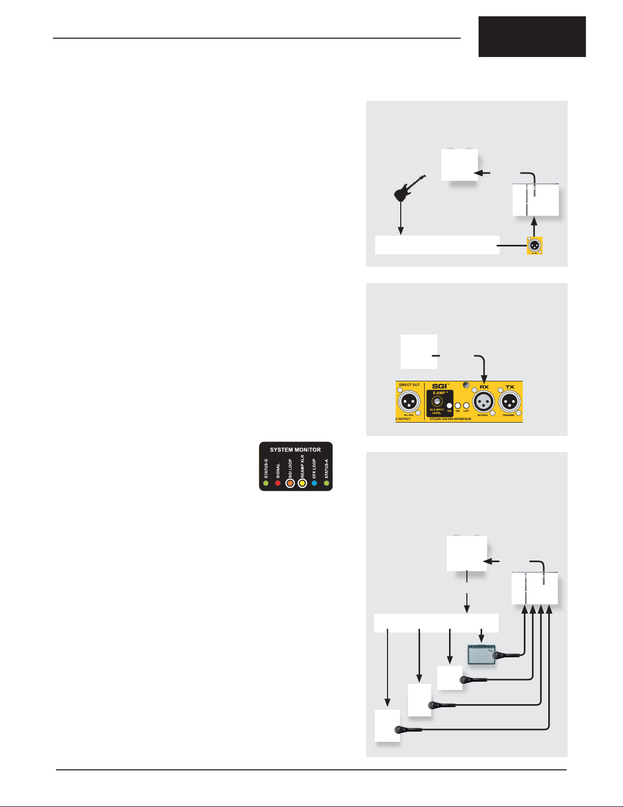
HOW IT WORKS
Re-amping begins by recording a dry track from the JX44’s DIRECT OUT to a
multi-track recorder. This could be done during a live performance or right in
the studio during basic tracks. Afterwards, the dry track is sent from the multitrack back to the JX44 using the X-AMP’s XLR input. The X-AMP interface
converts the +4dB low-Z balanced line-level signal from the multi-track to a
hi-Z instrument-level, allowing the multi-track to drive the amps and effects just
like a guitar would.
RE-AMPING PROCESS
1. RECORD DRY TRACK
• Record a dry track using the DIRECT output.
RECORD
DIRECT
OUT
2. MAKE CONNECTIONS
• Route multi-track output to X-AMP input.
PLAYBACK
SETTING UP
Use an XLR mic cable to connect the output of your recording system to the
SGI-RX jack on the rear panel. This XLR jack is shared by the X-AMP and SGI
interface to save space. After connecting, depress
the ON switch at the rear panel for both the SGI
and X-AMP. The SGI LOOP and X-AMP LEDs in
the SYSTEM MONITOR will illuminate. Note that
the JX44 inputs are disabled when the X-AMP
is active.
The SGI-RX input is transformer isolated to help eliminate ground loops
between the recording equipment and the JX44. If you hear hum or buzz
toggle the ground LIFT switch in the SGI section on the rear panel as this will
further reduce noise.
Now route the dry track from the recording system to the balanced X-AMP
input. From the JX44 set up your amps and effects and play the track. Set the
recessed LEVEL control in the X-AMP section of the rear panel so the amps
produce the same amount of gain or drive as your guitar does. Use a guitar
pick to turn the recessed control on the rear panel until it sounds right to you.
Set up microphones for the amps and you’re all set to re-record the dry track
through your amps to a new track on your recording system.
EXAMPLE: FIXING LIVE TRACKS IN POST PRODUCTION
Re-amping was born decades ago in the studio as a production technique.
With a little forethought you can employ it to make your live recordings
better too. Recording a dry track of all your instruments during a live concert
performance allows it to be used later in post production to overdub or even
replace guitar tracks recorded during the concert. When replacing a live track
with a re-amped track, the most important part is to set up the same effects,
amps and mics used during the live performance. This will help match the tone
of the live tracks.
3. RECORD NEW TRACKS
• Setup the JX44 with effects and amps.
• The multi-track drives the amps via the X-AMP.
• Record the results to new track(s).
RECORD
PLAYBACK
There is a lot to experiment with when it comes to re-amping as anyone who’s
done it will attest to. Just remember to emerge once in a while to eat.
Radial Engineering Ltd. JX44 Owner’s Manual
17
Page 20

True to the Music
FREQUENTL Y ASKED QUESTIONS
Q: Can I connect my guitar through an effect pedal to the JX44?
A: Yes. The inputs and outputs of the JX44 are unity gain so you
can place effects before and after the JX44.
Q: Can I use the JX44 with a bass guitar?
A: Yes. Not only bass but also acoustic guitar, pedal steel,
mandolin, fi ddle, string bass, or any instrument with a pickup and
a high impedance output.
Q: Can I connect a piezo contact pickup directly to the JX44?
A: No. For the best sound use an active preamp such as the
Radial PZ-Pre. Its piezo preamp brings the signal level from
the piezo element up to typical instrument level of most electric
instruments.
Q: Is the JX44 as good as the JD7 for recording?
A: Yes. The JX44 uses our proprietary Class-A signal path along
with high quality transformers and Drag™ control as found in the
JD7 giving it the same excellent sound quality. The additional SGI
and X-AMP features make it an excellent creative device for the
studio.
Q: Can the JR5 remote control both inputs and outputs?
A: Yes. You’ll need two JR5 footswitches. One connects to the
GUITARS remote jack. A second JR5 connects to the AMPS
remote jack. This allows the two JR5 footswitches to be in
different locations. For instance, one JR5 could be located
downstage for the artist to select amps while the technician
controls instrument selection with a second JR5 from the
backline.
Q: Can I use the JX44 in a stereo setup?
A: Yes. A stereo setup could take different forms depending
on what other components you would like to incorporate. You
could use the dual OUTPUT-3 and 4 jacks to connect a stereo
processor and drive two amps or the PA system with a stereo
signal.
Q: Can the JX44 integrate into a MIDI controlled guitar rig?
A: Yes. While the JX44 is not designed to accept MIDI commands
directly, the EFX LOOP acts as an audio access point for a MIDI
effects loop switcher.
Q: Can I control the EFX LOOP by footswitch?
A: Yes. You can assign one of the four amplifi er outputs as a
master effects switch and turn the effects loop on and off with the
JR5 remote footswitch.
Q: How far away can the JX44 be from the amplifi ers?
A: The amplifi er outputs on the back of the JX44 are buffered
and low impedance for driving long unbalanced cables up to 15
meters (50 ft.) without signifi cant signal loss. Cables with good
shielding should always be used with the JX44.
Q: How does the JX44 store the programmed banks?
A: The JX44 uses fl ash memory to store the amplifi er scenes you
program. There is no battery to replace and banks are stored
indefi nitely even when the power is disconnected.
Q: Why are there two XLR jacks on the back of the JR5?
A: These are parallel connections that can make arranging your
pedalboard more convenient by allowing the control cable to exit
at either side. Choose the one that best fi ts your pedalboard.
Alternatively the JR5 could connect and control two JX44 units for
an extra large or stereo rig.
TROUBLE SHOOTING
1. No Power:
• Check the power connection on the rear panel. Use the cable
clamp to prevent accidental disconnect.
• Ensure the power supply is plugged into a working outlet.
2. No sound at amplifi er outputs:
• Check the front panel LED indicators and ensure an instrument
input and amplifi er output are selected.
• Ensure the MUTE function is not active.
• Check the SIGNAL LED in the SYSTEM MONITOR. If the LED
is not fl ashing when you play your guitar, signal is not getting to
the inputs. Check your cables and connections from the guitar to
the JX44 input.
• Look for the SGI LOOP LED in the SYSTEM MONITOR. If this
LED is illuminated and you are not using SGI-44 the signal will
be interrupted. Turn the SGI LOOP off at the rear panel.
3. The amplifi ers are making a loud humming noise:
• Depress the four recessed LIFT switches for outputs 1 thru 4.
• Swap out the cables between the JX44 and the amp.
• Plug all your amps and effects into the same power bar to
minimize ground loops.
4. Some guitars are louder than others:
• Louder instruments with active preamps or wireless systems
should be connected to INPUT-3 and 4 where the TRIM controls
can be used to reduce levels to match quieter instruments.
5. Sound is distorted:
• The JX44 inputs are designed for electronic instruments. Ensure
the inputs are not being over-driven by a line-level preamp,
wireless or effect pedal. For instance, some wireless receivers
can be set up to output line-level signals that may saturate the
output transformers.
6. Turning on more than one amp does not increase the volume:
• Ensure the 180° polarity controls for OUTPUT-1 thru 4 have
been properly setup. See the “Setting up Guitars and Amps”
section.
7. No sound when using the SGI-44:
• Check for the SGI LOOP LED in the SYSTEM MONITOR. If not
illuminated turn the SGI interface on at the rear panel switch.
• Ensure the power supply is plugged into a working outlet
and connected to the SGI-44. The cable clamp can prevent
accidental disconnect.
• Check your cables and connections between your pedals and
the JX44 SEND and RECV jacks.
8. No effects can be heard:
• Check the EFX LOOP LED in the SYSTEM MONITOR. If not
illuminated turn on an amplifi er output assigned to the effects.
• Check your cables and connections between your pedals and
the JX44 SEND and RECV jacks.
9. No sound or bad sound when using the X-AMP:
• If there is no sound check the SGI LOOP and RE-AMP (X-AMP)
LEDs in the SYSTEM MONITOR. If not illuminated turn the SGI
and X-AMP on at the rear panel switches.
• If sound is distorted turn the X-AMP level control down or reduce
the level coming from the source such as a mixing console.
• If there is a loud hum depress the LIFT switch in the SGI section
of the rear panel.
18
Radial Engineering Ltd.
10. The JR5 footswitch is not working properly:
• Disconnect the power to the JX44. When power is reconnected the microprocessor will boot up and restore normal
operation.
JX44 Owner’s Manual
Page 21

True to the Music
SPECIFICATIONS & BLOCK DIAGRAM
INPUT A
INPUT B
INPUT C
INPUT D
DRAG
BUFFER
DRAG
BUFFER
LEVEL
BUFFER
LEVEL
BUFFER
ON
GUITAR 1
ON
GUITAR 2
ON
GUITAR 3
ON
GUITAR 4
BUFFER
ISOLATION
TRANSFORMER
X-AMP INPUT
SGI RTN
GROUND LIFT
INPUT-D
SELECT
TUNER OUT
SGI SEND
X-AMP LEVEL
DIRECT BOX
PRE/POST EFX
SELECT
ON
X-AMP ON
SGI ON
180º REVERSE
ISOLATION
TRANSFORMER
PANIC
ON
SEND
GND LIFT
ON
EFX
LOOP
RETURN
SIGNAL
PRESENT
ON
F/X ON
RADIAL
DIRECT BOX.
OUTPUT
MUTE
ON
180º POL REVERSE
AMP 1
BUFFER
ON
BUFFER
ON
AMP 2
ISOLATION
TRANSFORMER
GND LIFT
ISOLATION
TRANSFORMER
GND LIFT
180º POL REVERSE
180º POL REVERSE
OUTPUT-1
OUTPUT-2
OUTPUT-3A
ISOLATION
ON
TRANSFORMER
BUFFER
AMPS 3
ISOLATION
TRANSFORMER
GND LIFT
OUTPUT-3B
180º POL REVERSE
180º POL REVERSE
OUTPUT-4A
ISOLATION
ON
TRANSFORMER
GND LIFT
ISOLATION
AMPS 4
BUFFER
TRANSFORMER
OUTPUT-4B
180º POL REVERSE
JX44 SPECIFICATIONS
Circuit Type: Radial proprietary Class-A signal path
Instrument Inputs: 4 x ¼” Hi-Z at rear panel
2 x ¼” Hi-Z front panel (paralleled with rear INPUTSA and INPUT-B, front jacks have priority over rear)
Inputs A & B have Drag™ control load correction
Inputs C & D have trim control
Input Impedance: Inputs A & B : variable w/ Drag™ from 10k - 1 meg
Ohm; Inputs C & D : 1 meg Ohm
Amplifi er Outputs: 6 x ¼” Hi-Z (unity gain) with 6 x Radial custom
wound transformers for amp isolation
Tuner Output: ¼” Hi-Z buffered instrument level (unity gain)
Local Effects Loop: Send ¼” Hi-Z output / Receive ¼” Hi-Z return (unity
gain)
Remote Effects Loop: 2 x Jensen™ transformers for SGI & X-Amp input
Direct Output: Class-A drive circuit with Radial custom wound
transformer for isolation; 1 x XLR balanced 600
Ohm mic-level output; AES-3 pin (pin-2 hot)
Frequency Response: 20Hz to 20kHz (+/-2.5dB)
Harmonic distortion: 001% (20Hz to 20kHz)
Phase distortion: 1 degree at 1Khz, 8 degrees at
20Hz
JR5 Remote Ports: 3-pin XLR remote control ports uses standard mic
cables to connect the JR5 footswitch
Other Connections: Remote control for the MUTE function: contact
closure input for momentary non-latching footswitch
Power Supply: 15 VDC 1A center positive (two supplied)
Construction: 14-gauge steel with baked enamel fi nish
Dimensions: JX44: 19” 1RU x 66” deep
JR5 footswitch: 1025” x 275” x 2”
SGI-44 interface: 425 x 5” x 2”
Weight: JX44: 7.6 lb (3.44 Kg)
JR5: 2.9 lb (1.32 Kg)
SGI-44: 1lb (.450 Kg)
Warranty: Radial 3-year limited transferable warranty
Radial Engineering Ltd. JX44 Owner’s Manual
19
Page 22

NOTES:
True to the Music
20
Radial Engineering Ltd.
JX44 Owner’s Manual
Page 23
RADIAL ENGINEERING LTD.
3 YEAR TRANSFERABLE WARRANTY
RADIAL ENGINEERING LTD. (“Radial”) warrants this product to be free from defects in material and workmanship and will remedy any such defects free of charge according to the terms of this warranty. Radial will
repair or replace (at its option) any defective component(s) of this product (excluding fi nish and wear and
tear on components under normal use) for a period of three (3) years from the original date of purchase. In
the event that a particular product is no longer available, Radial reserves the right to replace the product
with a similar product of equal or greater value. To make a request or claim under this limited warranty, the
product must be returned prepaid in the original shipping container (or equivalent) to Radial or to an authorized Radial repair center and you must assume the risk of loss or damage. A copy of the original invoice
showing date of purchase and the dealer name must accompany any request for work to be performed
under this limited and transferable warranty. This limited warranty shall not apply if the product has been
damaged due to abuse, misuse,misapplication, accident or as a result of service or modifi cation by any
other than an authorized Radial repair center.
THERE ARE NO EXPRESSED WARRANTIES OTHER THAN THOSE ON THE FACE HEREOF AND
DESCRIBED ABOVE. NO WARRANTIES WHETHER EXPRESSED OR IMPLIED, INCLUDING BUT
NOT LIMITED TO, ANY IMPLIED WARRANTIES OF MERCHANTABILITY OR FITNESS FOR A PARTICULAR PURPOSE SHALL EXTEND BEYOND THE RESPECTIVE WARRANTY PERIOD DESCRIBED
ABOVE OF THREE YEARS. RADIAL SHALL NOT BE RESPONSIBLE OR LIABLE FOR ANY SPECIAL,
INCIDENTAL OR CONSEQUENTIAL DAMAGES OR LOSS ARISING FROM THE USE OF THIS PRODUCT. THIS WARRANTY GIVES YOU SPECIFIC LEGAL RIGHTS, AND YOU MAY ALSO HAVE OTHER
RIGHTS, WHICH MAY VARY DEPENDING ON WHERE YOU LIVE AND WHERE THE PRODUCT WAS
PURCHASED.
www.radialeng.com
CAUTION: POTENTIAL FOR ELECTRIC SHOCK HAZARD
!
Caution must be used when connecting electronic equipment to the JX44. The JX44 bridges all electronic
equipment connected together so faulty wiring or incorrect grounding of any of the equipment may pose
a shock hazard and/or damage the JX44 or other connected equipment. The Radial JX44 is specifi cally
designed for use with amplifi ers with proper electrical safety grounds that have been approved by nationally
recognized electrical authorities such as UL in the United States, CSA in Canada and other similar bodies
in countries around the world. Using older “vintage” amplifi ers that do not have 3-prong power plugs should
be avoided.
It is the users full responsibility to ensure that proper electrical connections are maintained on all equipment
connected to the JX44 and that proper electrical building codes have been followed wherever the JX44 is
used. Damage to the JX44 or other connected equipment caused by improper connections is not covered
under the warranty. Radial Engineering Ltd. takes no responsibility for how the JX44 is connected or used.
Use of the Radial JX44 confi rms you have read this caution statement and take full responsibility. If you are
not 100% sure of your actions, please consult a qualifi ed technician for advice before using this device or
connecting any of your equipment to it.
Radial Engineering Ltd.
1588 Kebet Way, Port Coquitlam BC V3C 5M5
tel: 604-942-1001 • fax: 604-942-1010
email: info@radialeng.com • web: www.radialeng.com
Radial JX44™ Owner’s Manual - Part #R870-1187-00 • V1.0
Specifi cations and appearance are subject to change without notice.
!
 Loading...