

Page 1

j48 stereo user guide
jensen transformer equipped
active 48v phantom powered direct box
Radial Engineering Ltd.
1588 Kebet Way, Port Coquitlam BC V3C 5M5
Tel: 604-942-1001 • Fax: 604-942-1010 • Email: info@radialeng.com
Page 2

j48 stereo direct box
user guide
Introduction ........................................................................ 1
J48 Stereo Features .......................................................... 2
Making Connections .......................................................... 3
Using the PAD ...................................................................4
Using the Ground Lift......................................................... 4
Using Various Instruments ................................................. 5
Examples ........................................................................... 6
Using the High-pass Filter ................................................. 7
Using the Polarity Reverse ................................................ 7
Optional mounting accessories ......................................... 8
Specications .................................................................... 9
Block diagram .................................................................. 10
Radial Limited Warranty ....................................Back Cover
Thank you for purchasing the Radial J48 Stereo. This wonderful active direct box employs a unique internal switching
supply that employs 48 volt phantom power and steps it up to increase the signal handling while it lowers distortion of all
types. Part of the magic behind the design is that it enables the user to lift the audio ground connection to eliminate noise
without disconnecting the 48V phantom power source. This means that you can enjoy the benets of an active direct box
without having to resort to batteries or some form of external power supply. This makes the J48 Stereo a very effective DI
box for all types of instruments in both live stage and studio recording applications.
The J48 Stereo is in fact a very easy to use direct box that is purpose-made to be compact and quick to deploy. You simply
plug it in, turn on the phantom power and it goes to work. There are however a number of features built in that should be
understood in order to get the most out of your J48. So please take a few minutes to go through this user guide to ensure
you get the most out of it. If after you have read it, you nd yourself asking questions; please visit the FAQ section of the
web page. This is where we post updates and questions from users. If you still do not nd the answer or need further
clarication, we invite you to send us an email at info@radialeng.com and we will do our very best to reply in short order.
Now get ready to enjoy the world’s nest phantom powered active direct box!
Radial Engineering Ltd. J48 Stereo™ User Guide
1
Page 3
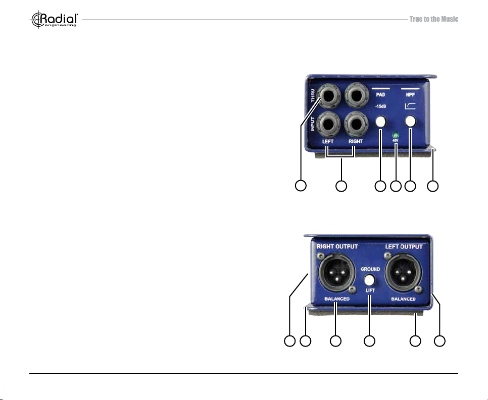
FEATURES
1. ¼” THRU-PUTS: Left and right parallel outputs used to
connect the hi-Z instrument signal to an amplier, tuner or
personal monitoring system.
2. ¼” INPUTS: Left and right unbalanced, hi-Z inputs used to
connect instruments.
3. -15dB PAD: Reduces the input sensitivity to prevent overload.
4. +48V: LED indicator will glow when the J48 Stereo is
receiving phantom power.
5. HPF: High-pass lter switch gently rolls off bass to remove
rumble and resonant feedback (-3dB @ 80Hz).
6. BOOKEND DESIGN: Creates a protective zone around the
switches and connectors.
7. 180° POLARITY (side panel): Reverses the polarity of the
RIGHT XLR output by toggling pins-2 and 3.
8. I-BEAM REINFORCED: 14-gauge steel enclosure with rigid
I-beam construction makes it impossible to torque the PC
board and cause solder joints to go cold.
9. XLR OUT: Left and right balanced, low impedance mic level
output. Wired to AES standard (pin-2 hot).
10. GROUND LIFT: Disconnects the ground from the audio
signal path and helps eliminate hum and buzz caused by
ground loops.
11. NO SLIP PAD: Provides electrical and mechanical isolation
and keeps the J48 Stereo from sliding around.
12. POWDER COAT FINISH: Durable nish keeps your J48
Stereo looking great for years.
1
8 9 11 12107
2 3 4 5 6
Radial Engineering Ltd. J48 Stereo™ User Guide
2
Page 4
OVERVIEW
The Radial J48 Stereo is an active direct box that derives its power from the 48 volt phantom supply from the mixing
console or mic preamp. You simply plug in and it will quietly go to work.
MAKING CONNECTIONS
As with all audio gear, always ensure audio system levels are turned down or equipment turned off before making connections. This will avoid plug-in or turn-on transients from damaging more sensitive components such as tweeters.
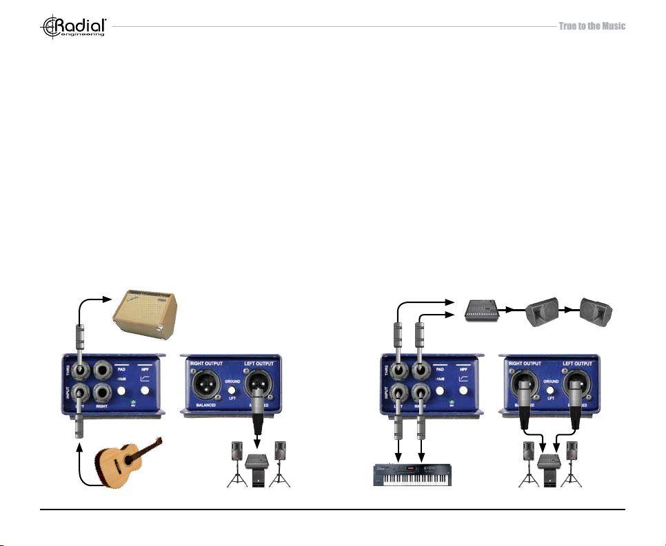
There are two channels on the J48. These are identical and feature a ¼” INPUT, a ¼” THRU-put and a balanced XLR out.
Connect your source instrument to the input and the balanced XLR out to the PA system or recorder. The THRU connector output provides the means for connecting the signal to a stage amp or personal monitor system. Simply connect the
THRU to your amp or monitor. Unbalanced cables are much more susceptible to noise than their balanced counterparts.
Keeping unbalanced cables under 8 meters (25’) in length is good practice while balanced cables can easily extend 100
meters (300’). The balanced output of the J48 Stereo is mic level, meaning that it should be connected to the mic input
of a mixing console or mic preamp. Once connected, make sure phantom power is activated. The green LED on the J48
Stereo will illuminate to let you know phantom power is present.
MonitorsSub-Mixer
ThruThru
InputsInputs
J48 Stereo with a keyboard, mixer and powered speaker.J48 Stereo with an acoustic guitar and stage amp.
Radial Engineering Ltd. J48 Stereo™ User Guide
3
Balanced OutsBalanced Out
Page 5

USING THE -15dB PAD
Inside the J48 Stereo is a unique switching power supply that is
designed to provide plenty of headroom even when pushed very
hard. There are however, instances when the output from an instrument can be extreme. To prevent distortion, the J48 Stereo
has a -15dB input pad that reduces the input sensitivity. Examples
could be a very high output digital piano, active bass guitar or
maybe the overly aggressive output from a DJ mixer. If you hear
distortion, simply depress the PAD.
USING THE GROUND LIFT
An active direct box is in essence a unity gain amplier that requires power to work. In the early days, active direct boxes typically employed a battery for power. Today, phantom power from
the console has become the most common power source. This
48 volt supply uses the pin-1 (ground) and pin-2 (hot) on the XLR
cable to provide DC power to the direct box while audio is sent in
the opposite direction over the same cable.
Radial Engineering Ltd. J48 Stereo™ User Guide
4
Page 6

GROUND LOOPS
A common problem occurs when connecting a stage amp to the direct box whereby a so called ground loop can present
itself. This is often caused by DC offsets or voltage differentials that can introduce hum and buzz in the sound system. The
rst line of defence is to lift the audio ground - pin-1 on the XLR. With most direct boxes, when you lift the ground you also
disconnect phantom power. This then requires using a battery or external supply to provide the power – options that are
not desirable. With the J48’s unique circuit design, instead of lifting the ground at the XLR, it is done in the power supply
section of the circuit board. This eliminates the noise problem without losing power. If you hear noise, simply depress the
ground lift switch.
SOURCE
GROUND LOOP HUM
The image above shows an audio source and a destination with a common electrical ground. As the audio also has a ground, these
combine to create a ground loop. The transformer and ground lift work together to eliminate the ground loop and potential noise.
Radial Engineering Ltd. J48 Stereo™ User Guide
EMI & RADIO NOISE
60Hz
Hum
ELECTRICAL GROUND PATH
5
TRANSFORMER
BREAKS THE LOOP
RECEIVE
Page 7

USING VARIOUS INSTRUMENTS
The J48 Stereo is active. This means that it has a built-in preamp or buffer circuit that drives the signal. This is the benet
of an active direct box over a passive counterpart. In other words, if you have a passive source such as an old Fender
bass, the J48 Stereo presents a very effective interface. Many sound engineers also prefer the added gain of an active
direct box on active instruments such as with acoustic guitars and vintage keyboards that may not have the optimal output.
In some instances the J48 Stereo can also improve signal to noise.
EXAMPLES OF INSTRUMENTS:
1. Fender bass to DI to amp and PA
PA
2. Acoustic guitar with active electronics to DI to PA
PA
Tuner
Amp
3. Upright bass to dedicated preamp to DI to PA 4. Stereo keyboard to DI to PA
PRE
AMP
PA
PA
Monitors
Radial Engineering Ltd. J48 Stereo™ User Guide
6
Page 8

USING THE HIGH-PASS FILTER
A very handy feature that is built into the J48 Stereo is the high-pass lter. When activated,
it gently rolls off low frequencies below 80Hz and helps eliminate resonance and feed-
back. This handy feature is particularly effective at cleaning up the low registers, making
it easier to mix.
The other benet with eliminating bass is that you actually increase the available dynamics. Low frequencies and their huge waves require more power than their high frequency
counterparts. Reducing low frequency content in the music program results in more available headroom and less distortion.
USING THE POLARITY REVERSE SWITCH
The RIGHT channel on the J48 Stereo is equipped with a polarity reverse switch that
toggles pin-2 and pin-3 on the XLR. This handy feature can be used in several ways:
1. Stereo Imaging
In some instances, particularly when recording – changing the relative phase between
the left and right channels can produce very pleasing results. Similarly, when using two
sources such as combining a magnetic pickup with a piezo on an acoustic guitar, changing the relative phase between them can sometimes produce a more natural sound.
2. Eliminating Feedback
Resonant feedback on a live stage is often produced when sound sources such as the
PA and stage amp combine to create a hot-spot at certain frequencies. This can cause
an acoustic instrument to vibrate, resulting in low frequency feedback. This can often be
minimized by reversing the polarity at the XLR, electronically moving the problem out of
the way, without having to resort to excessive (tone altering) equalization.
3. Adapting to non-AES standards
When interfacing with older vintage audio equipment, the polarity may be reversed whereby pin-3 may be hot. Depressing the polarity switch lets you match the phase if needed.
Radial Engineering Ltd. J48 Stereo™ User Guide
7
As this switch is recessed, use a
small screwdriver to activate.
Page 9
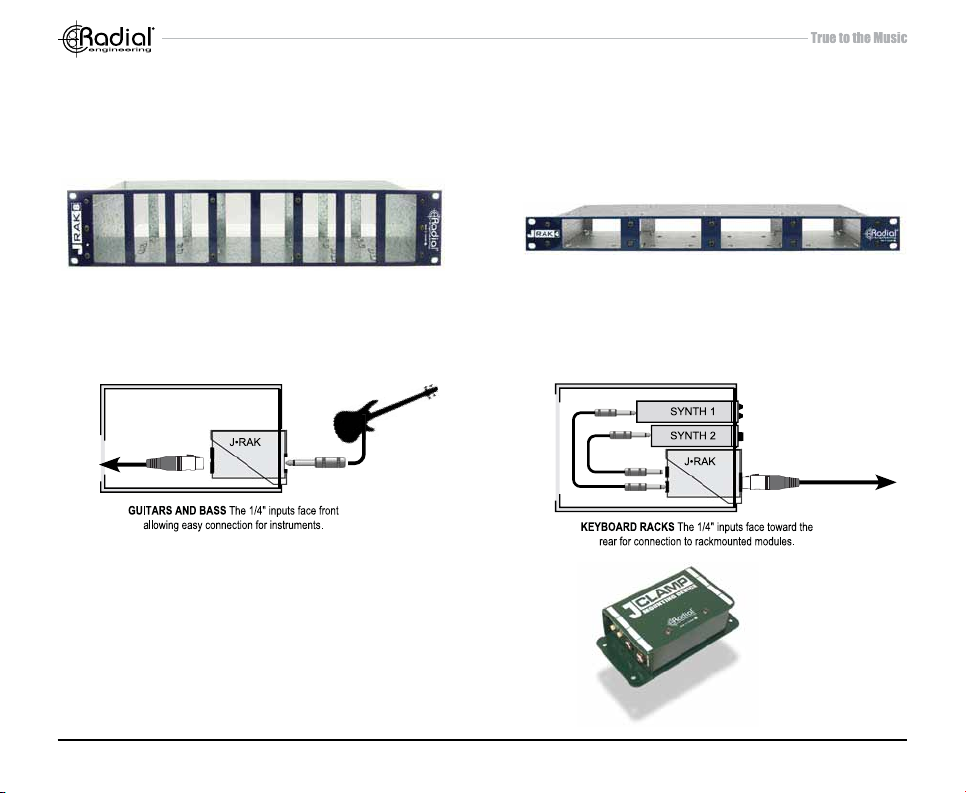
OPTIONAL RACK MOUNTING KITS
The J-Rak 8 and J-Rak 4 are an innovative rack mount chassis. The J-Rak 8 has eight vertical slots for Radial J48 Stereo direct
boxes or the other Radial J-Class products. The J-Rak 4 has four horizontal slots.
J-Rak 8 J-Rak 4
Each direct box can be front or rear mounted allowing the system designer to have the XLR’s on the front of the rack or rear,
depending on the application.
J-CLAMP
The J-Clamp is a mounting adapter that allows any of the
Radial J-Class products to be permanently mounted in locations such as in podiums, under board room tables and inside
amplifIer and effect racks. Features a heavy-duty steel shell
with built in mounting ange and user-writable tabs.
Radial Engineering Ltd. J48 Stereo™ User Guide
8
Page 10

SPECIFICATIONS
Audio circuit type: ..................................................................................... Proprietary analog circuit with low-noise op-amp
Frequency response: ..................................................................................................................................... 20Hz ~ 20KHz
Dynamic range: .......................................................................................................................................................... 109dB
Noise oor: .............................................................................................................................................. -99dB below 0dBu
Equivalent input noise: ............................................................................................................................................ -103dBu
Maximum input: ........................................................................................................................................................ +10dBu
Phase deviation: .....................................................................................................+10º at 20Hz | 0º at 1kHz | -1º at 20kHz
Total harmonic distortion:........................................................................................................................... 0.002% @ -5dBu
Inter-modulation distortion: ........................................................................................................................ 0.003% @ -3dBu
Input impedance: ........................................................................................................................................ 220kΩ - ¼” input
Output impedance: ..................................................................................................................................600Ω - XLR output
Input pad:.....................................................................................................................................................................-15dB
Polarity:.......................................................................................................180º signal polarity reverse - right channel only
Low-cut lter: .................................................................................................................................................. -3 dB @ 80Hz
XLR conguration: ......................................................................................................................... AES standard (pin-2 hot)
Power: ................................................................................................................... 48V phantom - internal switching supply
Construction: ........................................................................................................... 14 gauge steel chassis and outer shell
Finish: ................................................................................................................................................................Powder coat
Size:................................................................................................................................ 3.3” x 5.0” x 2” (84 x 127 x 48mm)
Weight: .......................................................................................................................................................... 1.55 lb (720 g)
FCC approval: .................................................................................................. Complies with section 15 of the FCC Rules
Conditions:.......................................................................................... For use in dry locations only between 5°C and 40°C
Warranty: .................................................................................................................................... Radial 3-year, transferable
Radial Engineering Ltd. J48 Stereo™ User Guide
9
Page 11

BLOCK DIAGRAM
J48 Stereo Block Diagram
PAD
INPUT
THRU
INPUT
THRU
SWITCH
PAD
SWITCH
Radial Engineering Ltd. J48 Stereo™ User Guide
HIGH-PASS
FILTER
SWITCH
BUFFER
HIGH-PASS
FILTER
SWITCH
BUFFER
10
PHASE
INVERTER
PHASE
INVERTER
IN+
ISOLATED
POWER
SUPPLY
IN-
180° POLARITY
REVERSE
SWITCH
CHASSIS
GROUND
VCC
TO
+
CIRCUIT
-
GROUND
LIFT
Page 12

RADIAL ENGINEERING
3 YEAR TRANSFERABLE WARRANTY
RADIAL ENGINEERING LTD. (“Radial”) warrants this product to be free from defects in material and workmanship and will remedy
any such defects free of charge according to the terms of this warranty. Radial will repair or replace (at its option) any defective
component(s) of this product (excluding nish and wear and tear on components under normal use) for a period of three (3) years
from the original date of purchase. In the event that a particular product is no longer available, Radial reserves the right to replace the
product with a similar product of equal or greater value. In the unlikely event that a defect is uncovered, please call 604-942-1001 or
email service@radialeng.com to obtain a RA number (Return Authorization number) before the 3 year warranty period expires. The
product must be returned prepaid in the original shipping container (or equivalent) to Radial or to an authorized Radial repair center
and you must assume the risk of loss or damage. A copy of the original invoice showing date of purchase and the dealer name must
accompany any request for work to be performed under this limited and transferable warranty. This warranty shall not apply if the
product has been damaged due to abuse, misuse, misapplication, accident or as a result of service or modication by any other than
an authorized Radial repair center.
THERE ARE NO EXPRESSED WARRANTIES OTHER THAN THOSE ON THE FACE HEREOF AND DESCRIBED ABOVE. NO
WARRANTIES WHETHER EXPRESSED OR IMPLIED, INCLUDING BUT NOT LIMITED TO, ANY IMPLIED WARRANTIES OF
MERCHANTABILITY OR FITNESS FOR A PARTICULAR PURPOSE SHALL EXTEND BEYOND THE RESPECTIVE WARRANTY
PERIOD DESCRIBED ABOVE OF THREE YEARS. RADIAL SHALL NOT BE RESPONSIBLE OR LIABLE FOR ANY SPECIAL, INCI-
DENTAL OR CONSEQUENTIAL DAMAGES OR LOSS ARISING FROM THE USE OF THIS PRODUCT. THIS WARRANTY GIVES
YOU SPECIFIC LEGAL RIGHTS, AND YOU MAY ALSO HAVE OTHER RIGHTS, WHICH MAY VARY DEPENDING ON WHERE
YOU LIVE AND WHERE THE PRODUCT WAS PURCHASED.
To meet the requirements of California Proposition 65, it is our responsibility to inform you of the following:
WARNING: This product contains chemicals known to the State of California to cause cancer, birth defects
or other reproductive harm.
Please take proper care when handling and consult local government regulations before discarding.
Radial Engineering Ltd.
1588 Kebet Way, Port Coquitlam BC V3C 5M5
Tel: 604-942-1001 • Fax: 604-942-1010 • Email: info@radialeng.com
Radial J48 Stereo™ User Guide - Part #: R870 1017 00 Copyright © 2015, all rights reserved. Appearance and specications subject to change without notice. This device complies with section 15 of the FCC Rules. Operation is subject to the following two conditions: (1) this device may not cause harmful interference, and (2) this device must accept any
interference received, including interference that may cause undesired operation.
 Loading...